VEX Super Classroom Bundle 12 Vex Starter Kits plus Sensors and Gears
|
|
|
- Ursula French
- 7 years ago
- Views:
Transcription

1 VEX Super Classroom Bundle 12 Vex Starter Kits plus Sensors and Gears The VEX Super Classroom Bundle was designed by the Carnegie Mellon Robotics Academy to ensure that your high school class has everything it needs to build and program advanced VEX robots. Twelve VEX starter kits are combined with 4 sensors line tracking, light, ultrasonic and optical shaft encoders and 3 gears - sprocket and chain, tank treads, advanced gears. Based on the Robotics Academy recommendation of one robot for every two students, this bundle will provide the foundation for a class of 24 students. Challenge your students to write more robust programs using the sensors. Students can experiment with more challenging and precise mechanical designs using the specialized gears. Robots can be programmed to operate autonomously, remote control or a combination of both. ROBOTC The Robotics Academy recommends ROBOTC for high school and college students. ROBOTC is a C-based programming language with a Windows environment for writing and debugging programs. ROBOTC is the only solution that offers a comprehensive, real-time debugger.
2 Teaching ROBOTC for IFI VEX is a Robotics Academy ROBOTC-based Curriculum provides teachers with multi-media, step-by-step instructions ranging from basic programming fundamentals to advanced sensor behavior. Take advantage of the Educators discount and free shipping. A subscription to five issues of Robot Magazine is included in this bundle free! ROBOTC Retail price $7,984 Educator's price $7,331
3 VEX Super Classroom Bundle Comparison Complete classroom teaching solution includes all programming & mechanical options. Note the only difference between the ROBOTC and EasyC bundles is the software & price. ROBOTC EasyC Product Code R E Retail price $7,984 $8,367 Educator's price $7,331 $7,447 What's included? Part number Quantity ROBOTC for VEX classroom license for 12 seats VX 1 12 single licenses of EasyC version Dongles VEX Starter Kit Power Pack Line Tracking Kits Ultrasonic Kits Optical Shaft Encoders Light sensors Sprocket and chain kits Tank tread kits Advanced Gear kits Crystal Upgrade Set A Crystal Upgrade Set B Robotics Academy VEX Curriculum Classroom license Free issues of Robot Magazine 5 Free Shipping!


4 Detailed list of parts included in VEX Super Classroom Bundle Micro Controller Specifications Inputs and Outputs Battery input 7.2 volts nominal, 6 to 9 volts min/max input range Battery Type 6 AA batteries (not included) or Vex Robotics Power Pack Interrupt inputs 6 Digital I/O 16 max with no Analog, Each can be input or Output (shared with Analog)
5 input Impendence Analog/Digital - The input consists of a 470K pull-up to +5V and a series resistance of 1K to the up. Interrupts - The input consists of a series resistance of 1K to the up. More info - input Schematic. Analog inputs 16 max with no Digital, 10-bit resolution (shared with Digital) Digital/Analog as inputs Interrupts as inputs Digital/Analog Interrupts as Outputs PWM Outputs Digital input Freq. Analog input Access Motor Output Serial Ports Pinout User Microcontroller Processor Speed Variable Space Program Space 32K Programming Programming Tools 3 db bandwidth of 150 khz, weak pull-up of 470k-ohms to 5.0 volts, need 0.0 to 0.6 volts for a low and 4.0 to 5.0 volts for a high 3 db bandwidth of 150 khz, weak pull-up of 47k-ohms to 5.0 volts, need 0.0 to 0.6 volts for a low and 4.0 to 5.0 volts for a high As outputs these ports can drive an open circuit to 0.6v or lower for a low and 4.0 volts or higher for a high. They can drive a 1 ma load to 1.6v or lower for a low and 3.0 volts or higher for a high. As outputs these ports can drive an open circuit to 0.6v or lower for a low and 4.0 volts or higher for a high. They can drive a 1 ma load to 1.0v or lower for a low and 3.6 volts or higher for a high. 50 KHz (typical) 10 µsec 8 PWM Outputs for motors or servos, refreshed every 18.5mSec RS232 Program (115Kb) and TTL Serial (115Kb) - RX and TX on Digital/Analog port Digital/Analog, Interrupts, Motor Outputs: Outside pin (closest to the controller edge) Ground Digital/Analog, Interrupts: Center pin (or middle pin) + 5 Volts, 1 Amp Max combined total from all pins Motor Outputs: Center pin (or middle pin) + Battery Power, 4 Amps Max combined total from all pins Digital/Analog, Interrupts, Motor Outputs: Inside pin (furthest from the controller edge) Signal / Control line User Programmable Micro-Controller Microchip PICmicro PIC18F MIPS (Million Instructions Per Second) 1800 bytes bytes EE2 PIC C Erase/Write 100,000 Microchip MPLAB IDE or easyc
6 Cycles Data Retention > 40 years General Features Size (W x L x H) 4.5" x 3.9" x 1.1" Weight 0.28 lbs. Battery 7.2V Rechargeable Nickel Cadmium batteries - NiCd Charging Recharge when battery voltage < 7.1V, full charge 7.8V typical Battery 7.2V Rechargeable Nickel Cadmium batteries - NiCd Current Draw 62 ma - Controller & Receiver min, 5mA to 2A per Motor, 20mA to 1.5 A per Servo Vex Robotics Design System - List of Contents Quantity 1 Description Vex Robotics Transmitter with Channel 61 TX module (75.41 MHz), (requires 8 AA batteries not included) 1 Vex Micro Controller 1 Vex Micro Controller Battery Pack (requires 6 AA batteries not included) 1 Vex Servo 3 Vex Motors 1 Inventor's Guide Notebook with Inserts 1 Vex RF Receiver Module with Channel 61 RX Crystal (75.41 MHz) 1 Vex Receiver Antenna Sleeve and Sleeve Holder 1 Nut Starter 2 Vex Limit Switches 2 Vex Bumper Switches 1 3 Wire (Black, Orange, White) Extension Cable 1 Interconnect Cable - connects the Receiver to Vex Micro Controller 2 Knobby Wheels 5 Vex Jumpers 16 Delrin Bearings 65 Keps nuts 2 Intake Rollers 2 All Purpose Wheels 4 Vex Angle with holes and slots, (5/8 x 5/8 x 15 in.) 20 Large Black Spacers
7 16 Collars with screws 14 Nylock Nuts 4 Low Friction Wheels with removable tires 2 Flat Plates, 5 x 15 hole (2.5 x 7.5 in.) 4 Flat Bars, 25 hole, (1/2 x 12 in.) 2 Drive Shaft Bars (12 in.) 20 Small Black Spacers 30 Metal Washers 1 Pack of replacement gears, internal gears for the motor and servo 10 Nylon Washers 6 Bearing Blocks 4 Shaft Lock Bars 4 60 Tooth Gears 4 36 Tooth Gears 4 12 Tooth Gears 2 Angle Gussets 4 Chassis Rails, (15/16 x 1/2 x 8 in.) 2 Chassis Angles, (1 x 1 x 7.5 in.) 1 Pack 4 inch Tie Wraps 70 1/4" 8-32 Screws 28 3/8" 8-32 Screws 28 1/2" 8-32 Screws 14 3/4" 8-32 Screws 10 1/2" 6-32 Screws 10 1/4" 6-32 Screws 4 Stub Shafts, attach clutch to motor 4 3 inch Threaded Beam, 8-32 threaded female-female Standoff 4 2 inch Threaded Beam, 8-32 threaded female-female Standoff 8 1 inch Threaded Beam, 8-32 threaded female-female Standoff 10 1/2 inch Threaded Beam, 8-32 threaded female-female Standoff 2 Pivot Gussets 2 Plus Gussets 4 3 inch Drive Shafts 4 2 inch Drive Shafts 1 Wrench 2 Allen Wrenchs, 3/32 and 5/64


8 Light Sensor Kit Light Sensor Kit - Technical Info Vex Robotics Useable range Detector Weight Wiring Technical Info 0 to 6 feet Photocell 0.03 lbs. Black - ground; Red - (+) power; White - control signal Light Sensor Kit - List of Contents Quantity Description 1 Light sensor /8" Screws 2 Keps nuts 1 Inventor's Guide Insert

 power; White - control signal Description 3 Line follower sensor 1")
9 Line Tracker Kit Line Tracker Kit - Technical Info Vex Robotics Sensor Type Description Infrared light sensor and infrared LED Line width 0.25 in. minimum, optimal line width is 0.5" Optimal Range Wiring Line Tracker Kit - List of Contents Quantity 3 millimeters (just under 1/8"), effectiveness drops off by approximately a factor of 10 at 5/8" Black - ground; Red - (+) power; White - control signal Description 3 Line follower sensor 1 Mounting bar, holds 3 line sensors /8" Screws 5 Keps nuts 1 Inventor's Guide Insert


10 Optical Shaft Encoder Kit Optical Shaft Encoder Kit - Technical Info Vex Robotics Technical Info Sensor Type Infrared light sensor and infrared LED Resolution 90 pulses per revolution Size 2 5/8" x 2" Weight 0.08 lbs. per sensor Shaft Size 1/8 inch square Wiring Black - ground; Red - (+) power; White - control signal Optical Shaft Encoder Kit - List of Contents Quantity Description 2 Optical Shaft Encoder /8" Screw 4 Keps Nut 1 Inventor's Guide Insert
 power; Orange -")

11 Ultrasonic Range Finder Ultrasonic Range Finder - Technical Info Vex Robotics Technical Info Useable range 3.0 centimeters meter / 1.5 inches inches Frequency 40 KHz Output Function Echo response from the ultrasonic sensor Output Wiring Black - ground; Red - (+) power; Orange - control signal input Function Start signal to the ultrasonic sensor input Wiring Black - ground; Red - (+) power; Yellow - control signal Weight 0.08 lbs. Ultrasonic Range Finder - List of Contents Quantity Description 1 Ultrasonic range finder sensor /8" Screws 2 Keps nuts 1 Inventor's Guide Insert


12 Sprocket and Chain Kit Sprocket and Chain Kit - Technical Info Vex Robotics Length Master links Center hole size Description 2 preassembled chains of 163 links each, total of 48 in. 326 total in. square Sprocket and Chain Kit - List of Contents Quantity Description 2 2 preassembled chains of 163 links each, total of 48 in. of chain 2 10-tooth sprockets 4 15-tooth sprockets 4 24-tooth sprockets 2 40-tooth sprockets 2 48-tooth sprockets 1 Inventor's Guide Insert


13 Advanced Gear Kit


14 Advanced Gear Kit - Designs / Application Worm Gear Bracket A top view to show the configuration inside. The configuration parts are not included. Worm Gear Bracket One side has been removed to show the internal configuration. The configuration parts are not included. Rack Gear Bracket The configuration parts are not included Rack Gear Bracket The configuration parts are not included.


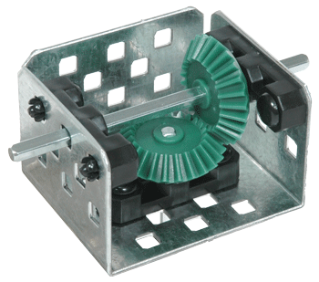

15 Bevel Gear Bracket The configuration parts are not included. Bevel Gear Bracket The configuration parts are not included. Bevel Gear Bracket The configuration parts are not included. Bevel Gear Bracket The configuration parts are not included.
16 Advanced Gear Kit - Technical Info Item 19-Tooth Rack Gear Worm Gear Differential Frame Description 8 sections, each 2.5 in. long. These can be combined continuously to create a rack of 20 in. 4 sections, each 0.75 in. long. requires (3) ea. of 24-tooth bevel gear. Square Hole Kit Weight in lbs. Advanced Gear Kit - List of Contents Quantity Description 8 19-tooth rack gear 2 12-tooth pinion gear 4 worm gears 4 worm wheel 1 differential frame 7 24-tooth bevel gear x 1/4 inch Button Head Screws
 each, total of 65.5 inches (laid in one continuous flat section) 170 total, each link is a Master link (change length by adding or removing links) 1.")

17 Tank Tread Kit Vex Robotics Tank Tread Kit - Technical Info Vex Robotics Length Master links Tread Width Technical Info 2 preassembled chains of 85 links (32.75 in.) each, total of 65.5 inches (laid in one continuous flat section) 170 total, each link is a Master link (change length by adding or removing links) 1.5 inches Tread Drive Diameter inches (approx) Material Center hole size Delrin plastic in. square Vex Robotics Tank Tread Kit - List of Contents Quantity Description 2 Preassembled chains of 85 links each, total of 65.5 in. of tread 4 Tank tread drive/idler wheels 4 Bogie wheels assemblies 2 Single Bogie wheels assemblies
18 x 1" Bogie wheels support screws 12 Keps nuts 1 Inventor's Guide Insert Carnegie Mellon Robotics Academy National Robotics Engineering Center Carnegie Mellon University Ten 40th Street Pittsburgh, PA
Motion. Table of Contents: Introduction to the Motion Subsystem 3.2. Concepts to Understand 3.8. Subsystem Interactions 3.26. Motion.
 Motion Table of Contents: Introduction to the Motion Subsystem 3.2 Concepts to Understand 3.8 Subsystem Interactions 3.26 3 1 Introduction to the Motion Subsystem The Motion Subsystem comprises all the
Vex Machinations: A Step-by-Step Project Guide
 Vex Machinations: A Step-by-Step Project Guide TM Version 1.0 Project Design and Programming: Justin Petersen (except where otherwise noted) Compilation: Yolande Petersen Justin Petersen and Yolande Petersen
Servo Motors (SensorDAQ only) Evaluation copy. Vernier Digital Control Unit (DCU) LabQuest or LabPro power supply
 Evaluation copy. Vernier Digital Control Unit (DCU) LabQuest or LabPro power supply") Servo Motors (SensorDAQ only) Project 7 Servos are small, relatively inexpensive motors known for their ability to provide a large torque or turning force. They draw current proportional to the mechanical
Servo Motors (SensorDAQ only) Project 7 Servos are small, relatively inexpensive motors known for their ability to provide a large torque or turning force. They draw current proportional to the mechanical
Servo Info and Centering
 Info and Centering A servo is a mechanical motorized device that can be instructed to move the output shaft attached to a servo wheel or arm to a specified position. Inside the servo box is a DC motor
Switch board datasheet EB007-00-1
 Switch board datasheet EB007-00-1 Contents 1. About this document... 2 2. General information... 3 3. Board layout... 4 4. Testing this product... 5 5. Circuit description... 6 Appendix 1 Circuit diagram
1. Lay out 2 pieces of 7/8" tubing and mark for bending as shown. Remember that the bend is in the shaded area as shown below in Figure 1.
 MINI BIKE PLANS Page 1 INTRODUCTION Before starting to build your Mini-Bike, be sure that you have all the parts shown on the material list. You will note that tubing has been used in the construction.
USED BUT NOT SHOWN: ITEMS 11-24.
 FO000900 - TABBING SYSTEM, MCS TABBER 2" Item Part Number Description Quantity 1 SM022604 Base Sub Assembly, MCS Tabber (2") 1 2 AF000512 Tabbing Head, MCS 2" 1 3 VC014001 Cable, Molded, DB25M-DB25F, 3
ROBOTC Software Inspection Guide with Additional Help Documentation
 VEX ROBOTICS COMPETITION ROBOTC Software Inspection Guide with Additional Help Documentation VEX Cortex Software Inspection Steps: 1. Cortex Firmware Inspection using ROBOTC 2. Testing Cortex Robots using
INTRODUCTION TO SERIAL ARM
 INTRODUCTION TO SERIAL ARM A robot manipulator consists of links connected by joints. The links of the manipulator can be considered to form a kinematic chain. The business end of the kinematic chain of
Gripper Kit for the Boe-Bot Robot (#28202)
") 599 Menlo Drive, Suite 100 Rocklin, California 95765, USA Office: (916) 624-8333 Fax: (916) 624-8003 General: info@parallax.com Technical: support@parallax.com Web Site: www.parallax.com Educational: www.stampsinclass.com
599 Menlo Drive, Suite 100 Rocklin, California 95765, USA Office: (916) 624-8333 Fax: (916) 624-8003 General: info@parallax.com Technical: support@parallax.com Web Site: www.parallax.com Educational: www.stampsinclass.com
LOW VOLTAGE D.C. MOTORS & GEARBOX UNITS
 LOW D.C. MOTORS & GEARBOX UNITS Printed on 100% recycled paper. 918D SERIES SINGLE RATIO METAL GEARBOX (RE280 MOTOR/RE 280/1 MOTOR) NEW! NEW! NEW! NEW! NEW! WITH 2mm OUTPUT SHAFT (15:1 ONLY) WITH 4mm OUTPUT
The quadrature signals and the index pulse are accessed through five 0.025 inch square pins located on 0.1 inch centers.
 Quick Assembly Two and Three Channel Optical Encoders Technical Data HEDM-550x/560x HEDS-550x/554x HEDS-560x/564x Features Two Channel Quadrature Output with Optional Index Pulse Quick and Easy Assembly
Three Channel Optical Incremental Encoder Modules Technical Data
 Three Channel Optical Incremental Encoder Modules Technical Data HEDS-9040 HEDS-9140 Features Two Channel Quadrature Output with Index Pulse Resolution Up to 2000 CPR Counts Per Revolution Low Cost Easy
Testing Robots Using the VEXnet Upgrade
 Testing Robots Using the VEXnet Upgrade This document is an inspection guide for VEX v1.5 microcontroller-based robots. Use this document to test if a robot using the VEXnet Upgrade is competition ready.
Multi Function, User Configurable Remote Vehicle Security System with 4 Button Replaceable Membrane Remote Transmitter
 MODEL PRO-9744 INSTALLATION MANUAL Multi Function, User Configurable Remote Vehicle Security System with 4 Button Replaceable Membrane Remote Transmitter This System Allows The Transmitter Buttons To Be
MANUAL FOR RX700 LR and NR
 MANUAL FOR RX700 LR and NR 2013, November 11 Revision/ updates Date, updates, and person Revision 1.2 03-12-2013, By Patrick M Affected pages, ETC ALL Content Revision/ updates... 1 Preface... 2 Technical
QR12 (1.22 ) Diameter Optical Encoder
 Diameter Optical Encoder") Improving the Quality of Life through the Power in Light QPhase QR12 (1.22 ) Diameter Optical Encoder Design Features: Low profile assembled height of Bearing design simplifies encoder attachment Resolutions
Improving the Quality of Life through the Power in Light QPhase QR12 (1.22 ) Diameter Optical Encoder Design Features: Low profile assembled height of Bearing design simplifies encoder attachment Resolutions
Ocean Controls RC Servo Motor Controller
 Ocean Controls RC Servo Motor Controller RC Servo Motors: RC Servo motors are used in radio-controlled model cars and planes, robotics, special effects, test equipment and industrial automation. At the
The $25 Son of a cheap timer This is not suitable for a beginner. You must have soldering skills in order to build this kit.
 The $25 Son of a cheap timer This is not suitable for a beginner. You must have soldering skills in order to build this kit. Micro Wizard has been manufacturing Pinewood Derby timers for over 10 years.
FLYPORT Wi-Fi 802.11G
 FLYPORT Wi-Fi 802.11G System on module 802.11g WIFI - Infrastructure mode - softap mode - Ad hoc mode Microchip PIC 24F 16 bit processor Microchip MRF24WG0MA/MB - Native WiFi 802.11g transceiver - PCB
ILLUSTRATED PARTS LIST
 TW400 WITH 390cc HONDA ENGINE 390cc 2 WHEEL DRIVE UTILITY VEHICLE ILLUSTRATED S LIST 390cc 2WD B O D Y D I A G R A M 390cc 2WD F R A M E D I A G R A M 390cc 2WD D R I V E T R A I N D I A G R A M DESCRIPTION
DIY Y6. Build Manual V.A 2014
 DIY Y6 Build Manual V.A 2014 1 Contents Thanks for purchasing a DIY Y6! These instructions will show you how to assemble a Y6 using the Pixhawk autopilot system and ArduCopter/APM:Copter firmware. If you
USER MANUAL V5.0 ST100
 GPS Vehicle Tracker USER MANUAL V5.0 ST100 Updated on 15 September 2009-1 - Contents 1 Product Overview 3 2 For Your Safety 3 3 ST100 Parameters 3 4 Getting Started 4 4.1 Hardware and Accessories 4 4.2
Product Information S N O. Portable VIP protection CCTV & Alarm System 2
 Product Information S N O Portable VIP protection CCTV & Alarm System 2 G O V E R N M E N T A L S E C U R I T Y S O L U T I VIP KIT Rapid Deployment VIP Protection Kit The VIP KIT has been designed to
Talon and Talon SR User Manual
 Talon and Talon SR User Manual Brushed DC motor controller Version 1.3 Cross the Road Electronics, LLC www.crosstheroadelectronics.com Cross The Road Electronics, LLC Page 1 4/2/2013 Device Overview Clear,
Space Duel, Gravitar, Black Widow MultiVector INSTALL GUIDE
 Space Duel, Gravitar, Black Widow MultiVector INSTALL GUIDE The Space Duel 3 in1 MultiVector kit includes the main PWB pictured above. IF YOU HAVE AND PROBLEMS OR SUGGESTIONS ON HOW TO IMPROVE THIS INSTALL
Byonics Micro Trak 1000 High Altitude Balloon Tracker
 Byonics Micro Trak 1000 High Altitude Balloon Tracker The Micro Trak 1000 (MT 1000) is a high altitude balloon (HAB) tracker. It is usually sold as a combination to provide a simple, turn key tracking
FRC WPI Robotics Library Overview
 FRC WPI Robotics Library Overview Contents 1.1 Introduction 1.2 RobotDrive 1.3 Sensors 1.4 Actuators 1.5 I/O 1.6 Driver Station 1.7 Compressor 1.8 Camera 1.9 Utilities 1.10 Conclusion Introduction In this
CAUTION! THE 7I29 USES VOLTAGE AND POWER LEVELS THAT REPRESENT A HAZARD TO LIFE AND LIMB.
 7I29 MANUAL Rev 1.5 CAUTION! THE 7I29 USES VOLTAGE AND POWER LEVELS THAT REPRESENT A HAZARD TO LIFE AND LIMB. THE 7I29 IS INTENDED FOR USE BY OEMS THAT WILL INTEGRATE IT INTO A SYSTEM WITH INTERLOCKS AND
JNIOR. Overview. Get Connected. Get Results. JNIOR Model 310. JNIOR Model 312. JNIOR Model 314. JNIOR Model 410
 The INTEG is an Ethernet I/O (digital, analog) device that monitors and controls a small set of process signals. functions as both basic I/O for integration with another application or system AND as a
CUSTOM AUXILIARY FORWARD LIGHTING KIT
 -J0 REV. 0--0 CUSTOM AUXILIARY FORWARD LIGHTING KIT GENERAL Kit Number -0, 0000 Models This Custom Auxiliary Lighting Kit adds lamps and turn signals to 00 and later FLHX model motorcycles. Additional
Tire pressure monitoring
 Application Note AN601 Tire pressure monitoring 1 Purpose This document is intended to give hints on how to use the Intersema pressure sensors in a low cost tire pressure monitoring system (TPMS). 2 Introduction
Part Name/Description Part Number Quantity. Power Cable 4000950-5 1
 Note: Indented items indicate parts included in an assembly listed above Part Name/Description Part Number Quantity Power Cable 4000950-5 1 Raven Harness Adapter Kit 4100525 1 Installation Instructions
EXPLORE 4-Leg Teaming Table with Screen Share Assembly Instructions
 EXPLORE 4-Leg Teaming Table with Screen Share Monitor Display Requirements: your flat panel display must confirm to the following requirements. y With the stand removed, the monitor must not exceed 40
DUMP TARP KITS MANUAL TARP KITS ELECTRIC TARP SYSTEMS MECHANICAL CRANK ARM TARP SYSTEMS
 ELECTRIC TARP & MANUAL SYSTEMS DUMP TARP KITS MECHANICAL CRANK ARM TARP SYSTEMS MANUAL TARP KITS ELECTRIC TARP SYSTEMS MECHANICAL CRANK ARM TARP SYSTEMS MANUAL TARP KITS TRAILER TARP KITS PARTS & ACCESSORIES
PowerFlex 700S and 700H Frame 12 DC Bus Connector Kit
 PowerFlex 700S and 700H Frame 12 DC Bus Connector Kit Installation Instructions This document provides instructions for the installation of a DC bus connector kit for PowerFlex 700S and 700H frame 12 drives
English AUTOMATION SYSTEMS FOR SLIDING GATES. Operating and installation instructions SLIDE SERIES
 English AUTOMATION SYSTEMS FOR SLIDING GATES Operating and installation instructions SLIDE SERIES v.0 Rev /202 INDEX ) General Safety Regulations... pág. 0 2) Description... pág. 02 3) Technical Specifications...
Hand Crank Generator (9 May 05) Converting a Portable Cordless Drill to a Hand Crank DC Generator
 Converting a Portable Cordless Drill to a Hand Crank DC Generator") Converting a Portable Cordless Drill to a Hand Crank DC Generator The unit is light weight (2.5 lb), portable, low cost ($10-$20) and can be used to recharge single cell batteries at from 1-3.5 amps. It
Converting a Portable Cordless Drill to a Hand Crank DC Generator The unit is light weight (2.5 lb), portable, low cost ($10-$20) and can be used to recharge single cell batteries at from 1-3.5 amps. It
HP UPS R1500 Generation 3
 HP UPS R1500 Generation 3 Installation Instructions Part Number 650952-001 NOTE: The rating label on the device provides the class (A or B) of the equipment. Class B devices have a Federal Communications
i ChatterBox! Motorcycle Security
 i Before you Start the Installation * Please read this manual to become familiar with the requirements necessary to complete the installation. * Use a high quality multi-meter to test all wires before
INSTALLATION AND OPERATING INSTRUCTIONS For Model GL1 Gate Locks
 Securitron Magnalock Corp. www.securitron.com ASSA ABLOY, the global leader Tel 800.624.5625 techsupport@securitron.com in door opening solutions INSTALLATION AND OPERATING INSTRUCTIONS For Model GL1 Gate
Section M POWER LIFTS
 Section M POWER LIFTS December 2009 1M Index 1. 53-520244-000 Poly V Idler Assembly 2. 53-520205-000 N.A. Mounting Bracket 3. 53-520212-000 Cable Assembly 4. 53-600149-000 Wire Harness Assembly 5. 53-860322-010
2/26/2008. Sensors For Robotics. What is sensing? Why do robots need sensors? What is the angle of my arm? internal information
 Sensors For Robotics What makes a machine a robot? Sensing Planning Acting information about the environment action on the environment where is the truck? What is sensing? Sensing is converting a quantity
TS93 EMR T/PT/TDE. Surface applied door closer
 TS EMR T/PT/TDE Surface applied door closer Installation instructions: Pull side track mount door closer with smoke detector (EMR T) Push side track mount door closer with smoke detector (EMR PT) Double
MODELS 7007 Gorilla Cycle Alarm 7017 Gorilla Cycle Alarm with 2-way pager system 1017 2-way pager system
 MODELS 7007 Gorilla Cycle Alarm 7017 Gorilla Cycle Alarm with 2-way pager system 1017 2-way pager system Remote Control Motorcycle Alarm System Installation & Operation Instructions Sistema de Alarma de
User manual DinaSys DTC/DTS and DTC/DTZ
 PiCommIT has developed the DinaSys DTC/DTS and DinaSys DTC/DTZ turntable controller for the Fleischmann / Marklin Turntables in scale H0, H0m, TT, N and Z. One of the most important starting point was
Turbo X. www.smartwireless.co.uk. 594 channel UHF true diversity
 Turbo X 594 channel UHF true diversity The new Turbo X series from Smart Wireless is the culmination of two years of research and development into advanced wireless technology. Using sophisticated RF design
Wireless Security Camera
 Wireless Security Camera Technical Manual 12/14/2001 Table of Contents Page 1.Overview 3 2. Camera Side 4 1.Camera 5 2. Motion Sensor 5 3. PIC 5 4. Transmitter 5 5. Power 6 3. Computer Side 7 1.Receiver
MODELS 8007 Gorilla Cycle Alarm 8017 Gorilla Cycle Alarm with 2-way pager system 1018 2-way pager system
 MODELS 8007 Gorilla Cycle Alarm 8017 Gorilla Cycle Alarm with 2-way pager system 1018 2-way pager system Remote Control Motorcycle Alarm System Installation & Operation Instructions Sistema de Alarma de
Installation Guide. WSD-100 Wind Speed and Direction Sensor For XR5 Data Loggers. February, 2011
 WSD-100 Wind Speed and Direction Sensor For XR5 Data Loggers Installation Guide February, 2011 Pace Scientific Inc www.pace-sci.com Tel: 704-799-0688 sales@pace-sci.com 1 Disclaimer The following warranty
ABB Drives. User s Manual. Pulse Encoder Interface Module RTAC-01
 ABB Drives User s Manual Pulse Encoder Interface Module RTAC-0 Pulse Encoder Interface Module RTAC-0 User s Manual 3AFE 64486853 REV A EN EFFECTIVE:.5.00 00 ABB Oy. All Rights Reserved. Safety instructions
2003 ACCORD - Automatic Transmission Removal
 2003 ACCORD - Automatic Transmission Removal Special Tools Required Engine support hanger, A and Reds AAR-T-12566 Engine hanger balancer bar VSB02C000019 Front subframe adapter VSB02C000016 These special
PICNet 1. PICNet 1 PIC18 Network & SD/MMC Development Board. Features. Applications. Description
 Features PICNet 1 PIC18 Network & SD/MMC Development Board IC Sockets for 28 or 40-pin Microchip PIC18F Microcontrollers IC Socket for 8-pin serial EEPROM Multiple MCU Oscillator sources Full 10BaseT IEEE
VOYAGER 570G. 744A Sprayer Control
 VOYAGER 570G 744A Sprayer Control U S E R M A N U A L U S E R M A N U A L Table of Contents CHAPTER 1 - INTRODUCTION...1 SYSTEM CONFIGURATIONS...1 KIT CONTENTS...3 CONTROL HOUSING ASSEMBLY...5 CHAPTER
46431x92A Garden Tractor (1998) Page 1 of 16 Body Chassis
 Page 1 of 16 Body Chassis") 46431x92A Garden Tractor (1998) Page 1 of 16 Body Chassis 46431x92A Garden Tractor (1998) Page 2 of 16 Body Chassis 1 092546E701 Bracket, Seat 2 091963 Z Plate Assembly, Switch 3 164X26 Spring, Compression
46431x92A Garden Tractor (1998) Page 1 of 16 Body Chassis 46431x92A Garden Tractor (1998) Page 2 of 16 Body Chassis 1 092546E701 Bracket, Seat 2 091963 Z Plate Assembly, Switch 3 164X26 Spring, Compression
X8 Option 2 - Technology
 moog AC DC AC 4 to 450 A 4 to 210 A Compact MSD Servo Drive TTL in out Specification X8 Option 2 - Technology TTL Encoder Simulation / TTL Master Encoder moog Specification Option 2 - Technology TTL encoder
Product Information. Gateway For Connecting EnDat Encoders to PROFIBUS-DP
 Product Information Gateway For Connecting EnDat Encoders to PROFIBUS-DP April 2012 PROFIBUS Gateway For Connecting EnDat Encoders Encoders with EnDat interface for connection via gateway All absolute
DIY QUAD. Build Manual V.A 2014
 DIY QUAD Build Manual V.A 2014 1 Contents Thanks for purchasing a DIY Quad! These instructions will show you how to assemble a Quad using the Pixhawk autopilot system and ArduCopter/APM:Copter firmware.
360 Automatic Chain Saw UT-10468 Page 1 of 15 Carburetor
 360 Automatic Chain Saw UT-10468 Page 1 of 15 Carburetor 360 Automatic Chain Saw UT-10468 Page 2 of 15 Carburetor 1 93205A 1 Repair Kit 2 93205A 1 Repair Kit 3 93205A 1 Repair Kit 4 93205A 1 Repair Kit
DOOR PARTS SECTION D-1
 DOOR PARTS SECTION D-1 1 11 10 11 9 8 1 1 7 6 10 5 4 D- DOOR ASSEMBLY ITEM NO DESCRIPTION QTY. PART NO 1 SERVICE DOOR ASSEMBLY ~ * CONTROL PANEL 1 * DOOR GUARD 1 * 4 DOOR ROLLER ASSEMBLY 1 1148-7 5 T-HANDLE
The NXT Generation. A complete learning solution
 The NXT Generation A complete learning solution The NXT Generation LEGO MINDSTORMS Education is the latest in educational robotics, enabling students to discover ICT, science, D&T and maths concepts in
Replacement Parts Catalog
 Replacement Parts Catalog Replacement Parts Contents A-Class Right Hand 4 Model Printer Assemblies... 1 Cover Assembly (15-3021-01)... 2 Display Assembly (24-2605-01)... 3 Direct Thermal (78-2474-01)...
BUILD A REVOLUTE COORDINATE ARM
 25 BUILD A REVOLUTE COORDINATE ARM The revolute coordinate arm design provides a great deal of flexibility, yet requires few components. The arm described in this chapter enjoys only two degrees of freedom.
POWER WAVE 455M/STT & (CE)
") Illustration of Sub Assemblies Illustration of Sub Assemblies Illustration of Sub Assemblies Illustration of Sub Assemblies P-450 P-450 PARTS LIST FOR POWER WAVE 455M/STT & (CE) P-450-A P-450-A ILLUSTRATION
Illustration of Sub Assemblies Illustration of Sub Assemblies Illustration of Sub Assemblies Illustration of Sub Assemblies P-450 P-450 PARTS LIST FOR POWER WAVE 455M/STT & (CE) P-450-A P-450-A ILLUSTRATION
TABLE OF CONTENTS. I. TROUBLESHOOTING... 2 - Section 1.01: Common Problems/Solutions... 2
 BAL Accu-Slide System I. Table of Contents TABLE OF CONTENTS I. TROUBLESHOOTING... 2 - Section 1.01: Common Problems/Solutions... 2 II. GETTING STARTED... 5 - Section 2.01: Tools You Will Need... 5 - Section
System theremino MasterDIL-V3
 System theremino MasterDIL-V3 System theremino - MasterDIL-V3 - Datasheet - March 8, 2013 - Page 1 The Master module The "Master" is the main module of the system Theremino. It puts in communication the
BUILDING INSTRUCTIONS
 etap2hw 38 mm I2C to LCD Interface BUILDING INSTRUCTIONS October 2013 P. Verbruggen Rev 1.01 15-Oct-13 Page 1 Table of Contents Chapter 1 General Information 1.1 ESD Precautions 1.2 Further Supplies 1.3
Description. Dimensions. Features. www.pwb-encoders.com. precision works better
 Description The MEC22 is a high resolution optical hollow shaft encoder that can be fixed quickly and easily on different sizes of motor shafts. The encoder provides two square wave outputs in quadrature
Required Supplies for Installing Check Tag Assembly
 Check Tag Assembly and Antenna Installation Instructions 411922-004 05/10 This document explains how to install and connect the check tag assembly and check tag antenna. Required Supplies for Installing
CAN bus board. www.matrixmultimedia.com EB018
 CAN bus board www.matrixmultimedia.com EB018 Contents About this document 3 Board layout 3 General information 4 Circuit description 5 Protective cover 6 Circuit diagram 7 2 Copyright About this document
New XUY roller sensors
 Do you want to simplify the sensor integration in your conveyor systems? New XUY roller sensors for packet, boxes, letters on roller conveyors. Telemecanique Sensor s OsiSense TM XUY photoelectric sensors
Depending on which elastic support you have you can secure the V2 power unit to the following seat bracket tubes: EXTERNAL DIAMETER 27.
 ASSEMBLY 1 - EPS V2 POWER UNIT (SOLUTION 5) 1.1 - POSITIONING INSIDE THE SEAT TUBE WITH ELASTIC SUPPORT IN THE SEAT BRACKET TUBE Depending on which elastic support you have you can secure the V2 power
Encoders. the incremental encoders format such as relective optical technology, transmissive optical technology
 the incremental encoders format such as relective optical technology, transmissive optical technology back devices, brakes and gearboxes at no extra cost to you. USA: +1 267 933 2105 Europe: +33 20928751
REEL LAWN MOWERS MASPORT 400-500-660
 Issue A June 2009 REF # 719046 REEL LAWN MOWERS MASPORT 400-500-660 Part number Model Engine MASPORT 019036 400 RRR B & S Series 475 MASPORT 019044 400 RRR Honda GX160 MASPORT 019046 500 RRR B & S Series
Introduction WELCOME TO LEGO MINDSTORMS EDUCATION
 NXT User Guide Introduction WELCOME TO LEGO MINDSTORMS EDUCATION LEGO MINDSTORMS Education is the next generation in educational robotics, enabling students to discover Science, Technology, Engineering
UniPi technical documentation REV 1.1
 technical documentation REV 1.1 Contents Overview... 2 Description... 3 GPIO port map... 4 Power Requirements... 5 Connecting Raspberry Pi to UniPi... 5 Building blocks... 5 Relays... 5 Digital Inputs...
12-Volt Negative Ground Installation Instructions
 12-Volt Negative Ground Installation Instructions For Part Number: 1141, 1164, 1165, 1181 CAUTION!!! Before installing, please read the following important information... 1. The Ignitor is designed for
Arecont Vision H.264 Color or Day/Night SurroundVideo Series Installation Manual
 0 P a g e H.264 Color or Day/Night SurroundVideo Installation Manual Inside the box: A. Arecont Vision SurroundVideo camera B. Mounting template C. RJ45 female to female coupler D. Hex key E. Security
Orbit PCI Mk 2 Network Card. User Manual. Part No. 502566 Issue 4
 Orbit PCI Mk 2 Network Card User Manual Part No. 502566 Issue 4 Information in this document is subject to change without notice. Companies, names and data used in examples herein are fictitious unless
Zlinx Wireless I/O. Peer-to-Peer and Modbus I/O B&B ELECTRONICS PRODUCT INFORMATION
 Modular, Customizable Wire Replacement 128 / 256 Bit AES Encryption Software Selectable RF Transmit Power Software Selectable Over-the-air Data Rate Modbus ASCII /RTU Compatible Wide Operating Temperature
C O N V E Y O R C O M P O N E N T S C H A I N S B E L T S B E A R I N G S
 C O N V E Y O R C O M P O N E N T S C H A I N S B E L T S B E A R I N G S January 2009 Issue 6 Valu Guide Brackets The Ultimate in Adjustability and Cost Savings Valu Guide brackets are part of a family
Oceanscience Cable Chimp II Cableway ROV System User Guide and Warranty
 Oceanscience Cable Chimp II Cableway ROV System User Guide and Warranty Page 1 Table of Contents Introduction Page 3 Overview Page 3 Setup and Operation Page 5 Remote Control Page 6 Power Management Page
DRTS 33. The new generation of advanced test equipments for Relays, Energy meters, Transducers and Power quality meters
 The new generation of advanced test equipments for Relays, Energy meters, Transducers and Power quality meters Testing all relay technologies: electromechanical, solid state, numerical and IEC61850 Manual
ELECTRONICS G H I J K L M
 ELECTRONICS TM LASER INSTALLATION INSTRUCTIONS PARTS KIT Parts Kit includes the following: A- (1) Universal Mounting Bracket A B- (1) Red L.E.D. Laser Alert Light C- (1) Piezo Beeper w/ O Ring Tape D-
Series 30000 Hose Reels
 Operating Instructions and Parts List for Series 30000 Hose Reels - MANUAL DRIVEN - - POWER DRIVEN - SAFETY PRECAUTIONS Personal injury and/or equipment damage may result if proper safety precautions are
SE-1200-EI. Operation & Parts Manual
 SE-1200-EI Operation & Parts Manual SE 1200 EI OWNERS MANUAL Table of Contents 1. Installation guide 2. Set-up instructions 3. Operation instructions 4. Cleaning 5. Troubleshooting 6. Parts manual 7. Electrical
MODEL 1211 CURRENT PREAMPLEFIER
 MODEL 1211 CURRENT PREAMPLEFIER Phone: (607)539-1108 Email: info@dlinstruments.com www.dlinstruments.com The Model 1211 Current Preamplifier was designed to provide all of the features required of a modern
GE Wireless Devices Battery Replacement
 60-506-319.5 Crystal Smoke Detector Two 9V Duracell 9V 1. Twist counter-clockwise until detector become loose from base. 2. Replace batteries observing correct polarity. 3. Replace detector by twisting
Kit 106. 50 Watt Audio Amplifier
 Kit 106 50 Watt Audio Amplifier T his kit is based on an amazing IC amplifier module from ST Electronics, the TDA7294 It is intended for use as a high quality audio class AB amplifier in hi-fi applications
Be careful when designing robots with multiple motors under simultaneous or heavy loading. There are three main points to consider:
 One of the most frustrating things that can happen to a team is losing control of their robot during a match. Please consider the following things that have been seen to cause problems at competition:
 UFO 1 FOLDER INDEX A2 FOLDING MACHINE TYPE 10060 LIST NO DESCRIPTION PAGE 10101M Main Assembly - Mechanical 2 10201M Main Roller Assembly 4 16101M Upper & Lower Perforator Shaft Assembly 6 12701M Primary
RS232 Board datasheet
 RS232 Board datasheet Contents 1. About this document 2. General information 3. Board Layout 4. Getting Started 5. Circuit Description Appendix 1 Circuit Diagram Copyright 2004 Matrix Multimedia Limited
Express5800/120Ed. Rack Mount Kit Installation Procedures PN: 455-01607-001
 Express5800/120Ed Rack Mount Kit Installation Procedures PN: 455-01607-001 Proprietary Notice and Liability Disclaimer The information disclosed in this document, including all designs and related materials,
ABB Drives. User s Manual HTL Encoder Interface FEN-31
 ABB Drives User s Manual HTL Encoder Interface FEN-31 HTL Encoder Interface FEN-31 User s Manual 3AUA0000031044 Rev B EN EFFECTIVE: 2010-04-06 2010 ABB Oy. All Rights Reserved. 5 Safety instructions
Small Optical Encoder Modules 480lpi Digital Output. Features. Applications VCC 3 CHANNEL A 2 CHANNEL B 4 GND 1
 HEDS-9730, HEDS-9731 Small Optical Encoder Modules 480lpi Digital Output Data Sheet Description The HEDS-973X is a high performance incremental encoder module. When operated in conjunction with either
B. Equipment shall be furnished and installed as specified. No substitutions will be allowed.
 CLASSROOM SOUNDFIELD DISTRIBUTION SYSTEM PART 1 GENERAL 1.1 RELATED DOCUMENTS: A. Drawings and general provisions of Contract, including General and Supplementary Conditions and Division-1 Specification
VEHICLE SPEED CONTROL SYSTEM
 PL VEHICLE SPEED CONTROL SYSTEM 8H - 1 VEHICLE SPEED CONTROL SYSTEM TABLE OF CONTENTS page DESCRIPTION AND SPEED CONTROL SYSTEM...1 SPEED CONTROL SERVO-PCM OUTPUT....2 SPEED CONTROL SWITCHES PCM INPUT...2
 ABLOY DA60 SWING DOOR OPERATOR Installation and commissioning manual Abloy Oy An ASSA ABLOY Group company APPROVALS / STANDARDS Low Voltage directive 7//EEC as amended by the directive 9/68/EEC EMC directive
DDS VFO CONSTRUCTION MANUAL. DDS VFO Construction Manual Issue 1 Page 1
 DDS VFO CONSTRUCTION MANUAL DDS VFO Construction Manual Issue 1 Page 1 Important Please read before starting assembly STATIC PRECAUTION The DDS VFO kit contains the following components which can be damaged
Mini Breakout-Board. CNC Interface for LPT Port. Installation Manual Version 4
 Mini CNC Interface for LPT Port Version 4 Product Brief This breakout-board is designed to connect up to four stepper or servo drives to the parallel port of a PC. This requires the use of a CNC controller