CSC 470 Computer Graphics. Light
|
|
|
- Constance Johnson
- 7 years ago
- Views:
Transcription
1 CSC 470 Computer Graphics Light
2 Definitions Illumination: the transport of energy from light sources to surfaces & points Note: includes direct and indirect illumination Lighting: the process of computing the luminous intensity (i.e., outgoing light) at a particular 3-D point, usually on a surface Shading: the process of assigning colors to pixels
3 Components of Illumination Two components of illumination: light sources and surface properties Light sources (or emitters) Spectrum of emittance (i.e., color of the light) Geometric attributes Position Direction Shape Directional attenuation
4 Components of Illumination Surface properties Reflectance spectrum (i.e., color of the surface) Geometric attributes Position Orientation Micro-structure Common simplifications in interactive graphics Only direct illumination from emitters to surfaces Simplify geometry of emitters to trivial cases
5 Lighting Three vectors are needed to compute the intensity of reflected light m: normal vector at a surface point v: vector from a surface point to the viewer s: vector from a surface point to the light
6 Lighting Two types of lights in scenes point light sources ambient light Light is absorbed, reflected, transmitted Reflected light diffuse specular
7 Ambient Light Sources Objects not directly lit are typically still visible E.g., the ceiling in this room, undersides of desks This is the result of indirect illumination from emitters, bouncing off intermediate surfaces Too expensive to calculate (in real time), so we use a hack called an ambient light source No spatial or directional characteristics; illuminates all surfaces equally Amount reflected depends on surface properties

8 Ambient Light Uniform background glow the amount of ambient light reflected depends on the material of the surface I = I a ρ where ρ a, a is the ambient reflection coefficient ρ a = 0, 0.1, 0.3, 0.5, 0.7
9 Ambient Light Sources For each sampled wavelength, the ambient light reflected from a surface depends on The surface properties, k ambient The intensity of the ambient light source (constant for all points on all surfaces ) I reflected = k ambient I ambient
10 Ambient Light Sources A scene lit only with an ambient light source:
11 Directional Light Sources For a directional light source we make the simplifying assumption that all rays of light from the source are parallel As if the source were infinitely far away from the surfaces in the scene A good approximation to sunlight The direction from a surface to the light source is important in lighting the surface With a directional light source, this direction is constant for all surfaces in the scene
12 Directional Light Sources The same scene lit with a directional and an ambient light source
13 Point Light Sources A point light source emits light equally in all directions from a single point The direction to the light from a point on a surface thus differs for different points: So we need to calculate a normalized vector to the light source for every point we light: l p

14 Point Light Sources Using an ambient and a point light source:

15 Other Light Sources Spotlights are point sources whose intensity falls off directionally. Requires color, point direction, falloff parameters Supported by OpenGL
 Good example: fluorescent light panels Capable of generating soft shadows (why?")
16 Other Light Sources Area light sources define a 2-D emissive surface (usually a disc or polygon) Good example: fluorescent light panels Capable of generating soft shadows (why? )
17 The Physics of Reflection Ideal diffuse reflection An ideal diffuse reflector, at the microscopic level, is a very rough surface (real-world example: chalk) Because of these microscopic variations, an incoming ray of light is equally likely to be reflected in any direction over the hemisphere: What does the reflected intensity depend on?
18 Diffuse reflection Reflected intensity does not depend on the direction of the viewer no contribution from the surface point to viewer vector Incoming light does depend on the direction of the light proportional to the area subtended by the facet Lamberts Law: intensity relationship between light source and surface orientation
19 Diffuse reflection Light to surface point vector parallel or nearly parallel to surface normal little variation in reflected intensity As light to surface point vector vector is perpendicular or nearly perpendicular to the surface normal small amount of reflection Model with the cosine dot product between s and m
20 Lambert s Cosine Law Ideal diffuse surfaces reflect according to Lambert s cosine law: The energy reflected by a small portion of a surface from a light source in a given direction is proportional to the cosine of the angle between that direction and the surface normal These are often called Lambertian surfaces Note that the reflected intensity is independent of the viewing direction, but does depend on the surface orientation with regard to the light source

21 Lambert s Law
22 Computing Diffuse Reflection The angle between the surface normal and the incoming light is the angle of incidence: l n θ I diffuse = k d I light cos θ In practice we use vector arithmetic: I diffuse = k d I light (n l)
 A Lambertian sphere seen at several different lighting")
23 Diffuse Lighting Examples We need only consider angles from 0 to 90 (Why?) A Lambertian sphere seen at several different lighting angles:

24 Diffuse reflection Lambert s model diffuse reflection s m I d I s ρ d MAX =, 0 s m where ρ is thediffuse reflective d constant ρ d = 0, 0.2, 0.4, 0.6, 0.8,1
25 Specular Reflection Shiny surfaces exhibit specular reflection Polished metal Glossy car finish A light shining on a specular surface causes a bright spot known as a specular highlight Where these highlights appear is a function of the viewer s position, so specular reflectance is view-dependent
ight = θ")
26 The Optics of Reflection Reflection follows Snell s Laws: The incoming ray and reflected ray lie in a plane with the surface normal The angle that the reflected ray forms with the surface normal equals the angle formed by the incoming ray and the surface normal: θ (l)ight = θ (r)eflection
27 Non-Ideal Specular Reflectance Snell s law applies to perfect mirror-like surfaces, but aside from mirrors (and chrome) few surfaces exhibit perfect specularity In general, we expect most reflected light to travel in direction predicted by Snell s Law But because of microscopic surface variations, some light may be reflected in a direction slightly off the ideal reflected ray As the angle from the ideal reflected ray increases, we expect less light to be reflected


28 Non-Ideal Specular Reflectance: An Empirical Approximation An illustration of this angular falloff: How might we model this falloff?
 in")
29 Phong Lighting The most common lighting model in computer graphics was suggested by Phong: I specular = k s I light ( ) n cosφ shiny The n shiny term is a purely empirical constant that varies the rate of falloff Though this model has no physical basis, it works (sort of) in practice v
30 Specular reflection Lighting highlights for shiny surfaces Phong model simple, reasonable results, OpenGL support Amount of reflected light is greatest when the reflection angle equals the incident angle reflected light falls off and reflection differes
31 Specular reflection r depends on s and m r = - s + 2 ( s m) m m 2 specular light falls off as the angle between r and v increases Phong models this drop-off as a cosine of the angle raised to a power (1-200) r v I sp I s ρ smax =, 0 r v where ρ is thespecular reflective s constant

32 Phong Lighting: The n shiny Term This diagram shows how the Phong reflectance term drops off with divergence of the viewing angle from the ideal reflected ray: What does this term control, visually?
33 Calculating Phong Lighting The cos term of Phong lighting can be computed using vector arithmetic: I specular = ksilight V is the unit vector towards the viewer R is the ideal reflectance direction ( Vˆ Rˆ ) nshiny An aside: we can efficiently calculate R Rˆ = ( ( ) 2 Nˆ Lˆ Nˆ Lˆ
 2 Nˆ Lˆ")
34 Calculating The R Vector Rˆ = ( ( ) 2 Nˆ Lˆ Nˆ Lˆ This is illustrated below: Rˆ + Lˆ = ( ( ) 2 Nˆ Lˆ )Nˆ

35 Phong Examples These spheres illustrate the Phong model as L and n shiny are varied:

36 Specular reflection ρ d = 0.25, 0.5, 0.75 f = 3, 6, 9, 25, 200
37 Total Light Add diffuse, specular, and ambient terms to compute the total amount of light that reaches the eye from a point P I = I ρ + I a a d s m ρ d max 0, + I s m sp h m ρ s max 0, h m
38 Colors OpenGL deals with colors individually computes red, green, and blue components separately I I I r g b = = = I I I ar ag ab ρ ar + I dr ρ dr ( lambert) + I spr ρ spr (phong) ρ ag + I dg ρ dg ( lambert) + I spg ρ spg (phong) ρ ab + I db ρ db ( lambert) + I spb ρ spb (phong) lambert = max 0, s m s m phong= max 0, h m h m
39
40 40
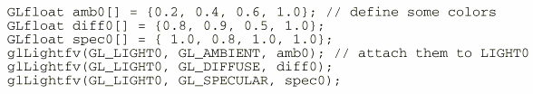
41 OpenGL Lighting Making a light source maximum of 8 light sources GL_LIGHT0, GL_LIGHT1, GL_LIGHT7 properties position ambient, diffuse, and specular components distance attenuation local or remote viewpoint front and back face lighting global ambient light 41
42 OpenGL Lighting Position directional or positional maintained in my LightInfo struct // Lighting static int numactivelights; typedef struct _LightInfo { GLfloat xyz[4]; GLfloat *rgb; int enable; } LightInfo; initialized with a single white light // Light information LightInfo linfo[] = { {{ 0.0f, 0.0f, 2.0f, 0.0f}, white}, }; const int MAX_LIGHTS = (sizeof(linfo) / sizeof(linfo[0])); 42
43 OpenGL Lighting Initialize OpenGL with LightInfo gllightfv(gl_light0 + num, GL_SPECULAR, dim); gllightfv(gl_light0 + num, GL_POSITION, linfo[num].xyz); gllightfv(gl_light0 + num, GL_DIFFUSE, linfo[num].rgb); Tell OpenGL to perform lighting calculations glenable(gl_lighting); for light num glenable(gl_light0 + num); Bind material properties glmaterialfv(gl_front, GL_AMBIENT, matamb); glmaterialfv(gl_front, GL_DIFFUSE, matdiff); glmaterialfv(gl_front, GL_SPECULAR, matspec); glmaterialfv(gl_front, GL_EMISSION, matemission); glmaterialf(gl_front, GL_SHININESS, 100.0); 43
44 OpenGL Lighting Front and back face rendering, default front face rendering only glcullface(gl_back); glenable(gl_cull_face); 44
45 OpenGL Lighting movable, directional, light change position after setting viewpoint // Change light angle, reset light position if (spinning_light) { light_angle = (light_angle + 1) % 360; linfo[0].xyz[1] = light_dist * sin(deg2rad(light_angle)); linfo[0].xyz[2] = light_dist * cos(deg2rad(light_angle)); gllightfv(gl_light0, GL_POSITION, linfo[0].xyz); } global ambient light // Global ambient light GLfloat modelamb[4] = {0.7, 0.1, 0.1, 1.0}; gllightmodelfv(gl_light_model_ambient, modelamb); 45
46 OpenGL Lighting Backfacelighting assign material properties to backfaces // Backface material properties for all shapes GLfloat matambback[4] = {0.0, 0.0, 0.2, 1.0}; GLfloat matdiffback[4] = {0.0, 0.0, 0.8, 1.0}; GLfloat matspecback[4] = {0.0, 0.0, 0.4, 1.0}; GLfloat matemissionback[4] = {0.0, 0.0, 0.2, 1.0}; bind material properties // bind backface material properties glmaterialfv(gl_back, GL_AMBIENT, matambback); glmaterialfv(gl_back, GL_DIFFUSE, matdiffback); glmaterialfv(gl_back, GL_SPECULAR, matspecback); glmaterialfv(gl_back, GL_EMISSION, matemissionback); glmaterialf(gl_back, GL_SHININESS, ); enable two sided lighting gllightmodelf(gl_light_model_two_side, GL_TRUE); 46
47 47
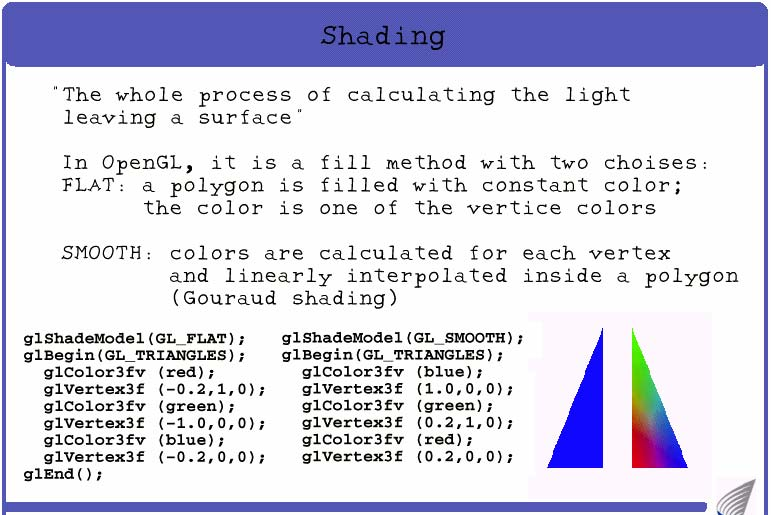
48 Flat Shading The simplest approach, flat shading, calculates illumination at a single point for each polygon: If an object really is faceted, is this accurate?
49 Is flat shading realistic for faceted object? No: For point sources, the direction to light varies across the facet For specular reflectance, direction to eye varies across the facet
50 Flat Shading We can refine it a bit by evaluating the Phong lighting model at each pixel of each polygon, but the result is still clearly faceted: To get smoother-looking surfaces we introduce vertex normals at each vertex Usually different from facet normal Used only for shading Think of as a better approximation of the real surface that the polygons approximate

51 Vertex Normals Vertex normals may be Provided with the model Computed from first principles Approximated by averaging the normals of the facets that share the vertex
52 Flat Shading 52
53 Gouraud Shading This is the most common approach Perform Phong lighting at the vertices Linearly interpolate the resulting colors over faces Along edges Along scanlines C 1 This is what OpenGL does Does this eliminate the facets? c 1 + t 1 (c 2 -c 1 ) C 3 c 1 + t 1 (c 2 -c 1 ) + t 3 (c 1 + t 2 (c 3 -c 1 )- c 1 + t 1 (c 2 -c 1 )) C 2 c 1 + t 2 (c 3 -c 1 )
54 Gouraud Shading Gouraud Shading Gouraud shading attempts to smooth out the shading across the polygon facets Begin by calculating the normal at each vertex N 54
55 Gouraud Shading Gouraud Shading A feasible way to do this is by averaging the normals from surrounding facets N Then apply the reflection model to calculate intensities at each vertex 55
56 Gouraud Shading Gouraud Shading We use linear interpolation to calculate intensity at edge intersection P I RED P = (1-α)I RED P1 + αi RED P2 where P divides P1P2 in the ratio α : 1 α Similarly for Q P1 P P2 P3 Q P4 56
57 Gouraud Shading Gouraud Shading Then we do further linear interpolation to calculate colour of pixels on scanline PQ P P2 P3 Q P1 57
58 Gouraud Shading 58
59 Gouraud Shading Limitations - Specular Highlights Gouraud shading gives intensities within a polygon which are a weighted average of the intensities at vertices a specular highlight at a vertex tends to be smoothed out over a larger area than it should cover a specular highlight in the middle of a polygon will never be shown 59
60 Gouraud Shading Artifacts Often appears dull, chalky Lacks accurate specular component If included, will be averaged over entire polygon C 1 C 3 C 2 Can t shade that effect!
61 Phong Shading Phong Shading Phong shading has a similar first step, in that vertex normals are calculated - typically as average of normals of surrounding faces N 61
62 Phong Shading Phong Shading However rather than calculate intensity at vertices and then interpolate intensities as we do in Gouraud shading... In Phong shading we interpolate normals at each pixel... N1 N2 P1 N P2 P P3 Q P4 62
63 Phong Shading Phong Shading... and apply the reflection model at each pixel to calculate the intensity -I RED, I GREEN, I BLUE N2 N N1 P2 P P3 Q P1 P4 63


64 Phong Shading Phong shading is not the same as Phong lighting, though they are sometimes mixed up Phong lighting: the empirical model we ve been discussing to calculate illumination at a point on a surface Phong shading: linearly interpolating the surface normal across the facet, applying the Phong lighting model at every pixel Same input as Gouraud shading Usually very smooth-looking results: But, considerably more expensive
65 Phong Shading Linearly interpolate the vertex normals Compute lighting equations at each pixel Can use specular component N 1 I total = k a I ambient + # lights i= 1 I i k d ( Nˆ Lˆ ) + k ( Vˆ Rˆ ) s n shiny N 4 N 3 Remember: Normals used in diffuse and specular terms N 2 Discontinuity in normal s rate of change is harder to detect
66 Phong Shading 66
67 Phong versus Gouraud Shading Phong versus Gouraud Shading A major advantage of Phong shading over Gouraud is that specular highlights tend to be much more accurate vertex highlight is much sharper a highlight can occur within a polygon Also Mach banding greatly reduced The cost is a substantial increase in processing time because reflection model applied per pixel But there are limitations to both Gouraud and Phong 67

68 Shortcomings of Shading Polygonal silhouettes remain Gouraud Phong

69 Gouraud versus Phong 69

70 Wall Lights 70


71 Wall Lights with Fewer Polygons 71

72 Simple Shading - Without Taking Account of Normals 72

73 Constant or Flat Shading - Each Polygon has Constant Shade 73
74 Gouraud Shading 74

75 Phong Shading 75
76 Phong Shading with Curved Surfaces 76

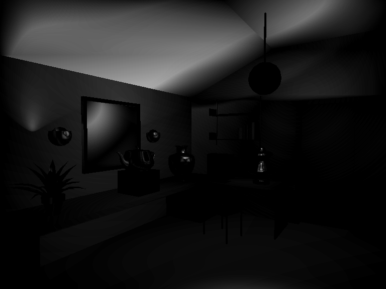
77 Better Illumination Model 77
Computer Applications in Textile Engineering. Computer Applications in Textile Engineering
 3. Computer Graphics Sungmin Kim http://latam.jnu.ac.kr Computer Graphics Definition Introduction Research field related to the activities that includes graphics as input and output Importance Interactive
Computer Animation: Art, Science and Criticism
 Computer Animation: Art, Science and Criticism Tom Ellman Harry Roseman Lecture 12 Ambient Light Emits two types of light: Directional light, coming from a single point Contributes to diffuse shading.
INTRODUCTION TO RENDERING TECHNIQUES
 INTRODUCTION TO RENDERING TECHNIQUES 22 Mar. 212 Yanir Kleiman What is 3D Graphics? Why 3D? Draw one frame at a time Model only once X 24 frames per second Color / texture only once 15, frames for a feature
Lesson 26: Reflection & Mirror Diagrams
 Lesson 26: Reflection & Mirror Diagrams The Law of Reflection There is nothing really mysterious about reflection, but some people try to make it more difficult than it really is. All EMR will reflect
Monash University Clayton s School of Information Technology CSE3313 Computer Graphics Sample Exam Questions 2007
 Monash University Clayton s School of Information Technology CSE3313 Computer Graphics Questions 2007 INSTRUCTIONS: Answer all questions. Spend approximately 1 minute per mark. Question 1 30 Marks Total
A Short Introduction to Computer Graphics
 A Short Introduction to Computer Graphics Frédo Durand MIT Laboratory for Computer Science 1 Introduction Chapter I: Basics Although computer graphics is a vast field that encompasses almost any graphical
Chapter 23. The Reflection of Light: Mirrors
 Chapter 23 The Reflection of Light: Mirrors Wave Fronts and Rays Defining wave fronts and rays. Consider a sound wave since it is easier to visualize. Shown is a hemispherical view of a sound wave emitted
CUBE-MAP DATA STRUCTURE FOR INTERACTIVE GLOBAL ILLUMINATION COMPUTATION IN DYNAMIC DIFFUSE ENVIRONMENTS
 ICCVG 2002 Zakopane, 25-29 Sept. 2002 Rafal Mantiuk (1,2), Sumanta Pattanaik (1), Karol Myszkowski (3) (1) University of Central Florida, USA, (2) Technical University of Szczecin, Poland, (3) Max- Planck-Institut
PRODUCT LIFECYCLE MANAGEMENT COMPETENCY CENTRE RENDERING. PLMCC, JSS Academy of Technical Education, Noida Rendering 1 of 16
 PRODUCT LIFECYCLE MANAGEMENT COMPETENCY CENTRE RENDERING PLMCC, JSS Academy of Technical Education, Noida Rendering 1 of 16 Table of contents Under construction PLMCC, JSS Academy of Technical Education,
Specular reflection. Dielectrics and Distribution in Ray Tracing. Snell s Law. Ray tracing dielectrics
 Specular reflection Dielectrics and Distribution in Ray Tracing CS 465 Lecture 22 Smooth surfaces of pure materials have ideal specular reflection (said this before) Metals (conductors) and dielectrics
Thea Omni Light. Thea Spot Light. Light setup & Optimization
 Light setup In this tutorial we will learn how to setup lights inside Thea Studio and how to create mesh lights and optimize them for faster rendering with less noise. Let us have a look at the different
Computer Graphics Global Illumination (2): Monte-Carlo Ray Tracing and Photon Mapping. Lecture 15 Taku Komura
: Monte-Carlo Ray Tracing and Photon Mapping. Lecture 15 Taku Komura") Computer Graphics Global Illumination (2): Monte-Carlo Ray Tracing and Photon Mapping Lecture 15 Taku Komura In the previous lectures We did ray tracing and radiosity Ray tracing is good to render specular
Computer Graphics Global Illumination (2): Monte-Carlo Ray Tracing and Photon Mapping Lecture 15 Taku Komura In the previous lectures We did ray tracing and radiosity Ray tracing is good to render specular
Science In Action 8 Unit C - Light and Optical Systems. 1.1 The Challenge of light
 1.1 The Challenge of light 1. Pythagoras' thoughts about light were proven wrong because it was impossible to see A. the light beams B. dark objects C. in the dark D. shiny objects 2. Sir Isaac Newton
GRAFICA - A COMPUTER GRAPHICS TEACHING ASSISTANT. Andreas Savva, George Ioannou, Vasso Stylianou, and George Portides, University of Nicosia Cyprus
 ICICTE 2014 Proceedings 1 GRAFICA - A COMPUTER GRAPHICS TEACHING ASSISTANT Andreas Savva, George Ioannou, Vasso Stylianou, and George Portides, University of Nicosia Cyprus Abstract This paper presents
Reflection and Refraction
 Equipment Reflection and Refraction Acrylic block set, plane-concave-convex universal mirror, cork board, cork board stand, pins, flashlight, protractor, ruler, mirror worksheet, rectangular block worksheet,
H.Calculating Normal Vectors
 Appendix H H.Calculating Normal Vectors This appendix describes how to calculate normal vectors for surfaces. You need to define normals to use the OpenGL lighting facility, which is described in Chapter
Reflectance Measurements of Materials Used in the Solar Industry. Selecting the Appropriate Accessories for UV/Vis/NIR Measurements.
 T e c h n i c a l N o t e Reflectance Measurements of Materials Used in the Solar Industry UV/Vis/NIR Author: Dr. Jeffrey L. Taylor PerkinElmer, Inc. 710 Bridgeport Avenue Shelton, CT 06484 USA Selecting
Maya 2014 Still Life Part 1 Texturing & Lighting
 Maya 2014 Still Life Part 1 Texturing & Lighting Realistic lighting and texturing is the key to photorealism in your 3D renders. Objects and scenes with relatively simple geometry can look amazing with
1051-232 Imaging Systems Laboratory II. Laboratory 4: Basic Lens Design in OSLO April 2 & 4, 2002
 05-232 Imaging Systems Laboratory II Laboratory 4: Basic Lens Design in OSLO April 2 & 4, 2002 Abstract: For designing the optics of an imaging system, one of the main types of tools used today is optical
Computer Graphics. Introduction. Computer graphics. What is computer graphics? Yung-Yu Chuang
 Introduction Computer Graphics Instructor: Yung-Yu Chuang ( 莊 永 裕 ) E-mail: c@csie.ntu.edu.tw Office: CSIE 527 Grading: a MatchMove project Computer Science ce & Information o Technolog og Yung-Yu Chuang
Optical Design Tools for Backlight Displays
 Optical Design Tools for Backlight Displays Introduction Backlights are used for compact, portable, electronic devices with flat panel Liquid Crystal Displays (LCDs) that require illumination from behind.
Technical Report An Analysis on the Use of LED Lighting for Video Conferencing
 An Analysis on the Use of Lighting for Video Conferencing Jim Yorgey, PE Frank Neher, Joe Volkert, and Christina Katrinak March 14, 2016 03/2016 Lutron Electronics Co., Inc. I P/N 367-2622 REV A 1) Abstract...
Image Processing and Computer Graphics. Rendering Pipeline. Matthias Teschner. Computer Science Department University of Freiburg
 Image Processing and Computer Graphics Rendering Pipeline Matthias Teschner Computer Science Department University of Freiburg Outline introduction rendering pipeline vertex processing primitive processing
Reflectance Characteristics of Accuflect Light Reflecting Ceramic
 Reflectance Characteristics of Accuflect Light Reflecting Ceramic Copyright July 1 Accuratus Corporation 35 Howard Street Phillipsburg, NJ 8865 USA +1.98.13.77 http://accuratus.com SUMMARY Accuflect is
The Lighting Effects Filter
 Appendix appendix E The Lighting Effects Filter The Lighting Effects filter is like a little program in itself. With this filter, you can create a wealth of different lighting effects, from making a particular
Last lecture... Computer Graphics:
 Last lecture... Computer Graphics: Visualisation can be greatly enhanced through the Introduction to the Visualisation use of 3D computer graphics Toolkit Visualisation Lecture 2 toby.breckon@ed.ac.uk
IT 386: 3D Modeling and Animation. Review Sheet. Notes from Professor Nersesian s IT 386: 3D Modeling and Animation course
 IT 386: 3D Modeling and Animation Review Sheet Sources: Notes from Professor Nersesian s IT 386: 3D Modeling and Animation course Notes from CannedMushrooms on YouTube Notes from Digital Tutors tutorial
Light Waves and Matter
 Name: Light Waves and Matter Read from Lesson 2 of the Light Waves and Color chapter at The Physics Classroom: http://www.physicsclassroom.com/class/light/u12l2a.html MOP Connection: Light and Color: sublevel
How many PIXELS do you need? by ron gibbs
 How many PIXELS do you need? by ron gibbs We continue to move forward into the age of digital photography. The basic building block of digital images is the PIXEL which is the shorthand for picture element.
Graphics Pipeline in a Nutshell
 Graphics Pipeline in a Nutshell How do we create a rendering such as this? CS334 Spring 2008 Design the scene (technical drawing in wireframe ) Apply perspective transformations to the scene geometry for
Geometric Optics Converging Lenses and Mirrors Physics Lab IV
 Objective Geometric Optics Converging Lenses and Mirrors Physics Lab IV In this set of lab exercises, the basic properties geometric optics concerning converging lenses and mirrors will be explored. The
An introduction to Global Illumination. Tomas Akenine-Möller Department of Computer Engineering Chalmers University of Technology
 An introduction to Global Illumination Tomas Akenine-Möller Department of Computer Engineering Chalmers University of Technology Isn t ray tracing enough? Effects to note in Global Illumination image:
ABS 731 Lighting Design & Technology. Spring 2006
 ABS 731 Lighting Design & Technology Spring 2006 AGI32 is used to predict the photometric performance of selected luminaires or daylight penetration in a simulated environment. The environments that can
ADVANCED THEORIES FOR CG LIGHTING
 ADVANCED THEORIES FOR CG LIGHTING 0.1 INTRODUCTION To become skilled at 3D lighting, one must have an understanding of how light works. CG lighting has been established based on rules from cinematography,
Procedure: Geometrical Optics. Theory Refer to your Lab Manual, pages 291 294. Equipment Needed
 Theory Refer to your Lab Manual, pages 291 294. Geometrical Optics Equipment Needed Light Source Ray Table and Base Three-surface Mirror Convex Lens Ruler Optics Bench Cylindrical Lens Concave Lens Rhombus
AP Physics B Ch. 23 and Ch. 24 Geometric Optics and Wave Nature of Light
 AP Physics B Ch. 23 and Ch. 24 Geometric Optics and Wave Nature of Light Name: Period: Date: MULTIPLE CHOICE. Choose the one alternative that best completes the statement or answers the question. 1) Reflection,
Cartoon-Looking Rendering of 3D-Scenes
 Cartoon-Looking Rendering of 3D-Scenes Philippe Decaudin 1 Research Report INRIA #2919 June 1996 Abstract We present a rendering algorithm that produces images with the appearance of a traditional cartoon
Scan-Line Fill. Scan-Line Algorithm. Sort by scan line Fill each span vertex order generated by vertex list
 Scan-Line Fill Can also fill by maintaining a data structure of all intersections of polygons with scan lines Sort by scan line Fill each span vertex order generated by vertex list desired order Scan-Line
Light Control and Efficacy using Light Guides and Diffusers
 Light Control and Efficacy using Light Guides and Diffusers LEDs 2012 Michael Georgalis, LC Marketing Manager, Fusion Optix October 11, 2012 Agenda Introduction What Is Light Control? Improves Application
Introduction to Computer Graphics
 Introduction to Computer Graphics Torsten Möller TASC 8021 778-782-2215 torsten@sfu.ca www.cs.sfu.ca/~torsten Today What is computer graphics? Contents of this course Syllabus Overview of course topics
Path Tracing. Michael Doggett Department of Computer Science Lund university. 2012 Michael Doggett
 Path Tracing Michael Doggett Department of Computer Science Lund university 2012 Michael Doggett Outline Light transport notation Radiometry - Measuring light Illumination Rendering Equation Monte Carlo
Advanced Computer Graphics. Rendering Equation. Matthias Teschner. Computer Science Department University of Freiburg
 Advanced Computer Graphics Rendering Equation Matthias Teschner Computer Science Department University of Freiburg Outline rendering equation Monte Carlo integration sampling of random variables University
Geometry Chapter 1. 1.1 Point (pt) 1.1 Coplanar (1.1) 1.1 Space (1.1) 1.2 Line Segment (seg) 1.2 Measure of a Segment
 1.1 Coplanar (1.1) 1.1 Space (1.1) 1.2 Line Segment (seg) 1.2 Measure of a Segment") Geometry Chapter 1 Section Term 1.1 Point (pt) Definition A location. It is drawn as a dot, and named with a capital letter. It has no shape or size. undefined term 1.1 Line A line is made up of points
Geometry Chapter 1 Section Term 1.1 Point (pt) Definition A location. It is drawn as a dot, and named with a capital letter. It has no shape or size. undefined term 1.1 Line A line is made up of points
COMP175: Computer Graphics. Lecture 1 Introduction and Display Technologies
 COMP175: Computer Graphics Lecture 1 Introduction and Display Technologies Course mechanics Number: COMP 175-01, Fall 2009 Meetings: TR 1:30-2:45pm Instructor: Sara Su (sarasu@cs.tufts.edu) TA: Matt Menke
Monte Carlo Path Tracing
 CS294-13: Advanced Computer Graphics Lecture #5 University of California, Berkeley Wednesday, 23 September 29 Monte Carlo Path Tracing Lecture #5: Wednesday, 16 September 29 Lecturer: Ravi Ramamoorthi
Lecture 12: Cameras and Geometry. CAP 5415 Fall 2010
 Lecture 12: Cameras and Geometry CAP 5415 Fall 2010 The midterm What does the response of a derivative filter tell me about whether there is an edge or not? Things aren't working Did you look at the filters?
Overview. What is EMR? Electromagnetic Radiation (EMR) LA502 Special Studies Remote Sensing
 LA502 Special Studies Remote Sensing") LA502 Special Studies Remote Sensing Electromagnetic Radiation (EMR) Dr. Ragab Khalil Department of Landscape Architecture Faculty of Environmental Design King AbdulAziz University Room 103 Overview What
LA502 Special Studies Remote Sensing Electromagnetic Radiation (EMR) Dr. Ragab Khalil Department of Landscape Architecture Faculty of Environmental Design King AbdulAziz University Room 103 Overview What
Deferred Shading & Screen Space Effects
 Deferred Shading & Screen Space Effects State of the Art Rendering Techniques used in the 3D Games Industry Sebastian Lehmann 11. Februar 2014 FREESTYLE PROJECT GRAPHICS PROGRAMMING LAB CHAIR OF COMPUTER
EXPERIMENT 6 OPTICS: FOCAL LENGTH OF A LENS
 EXPERIMENT 6 OPTICS: FOCAL LENGTH OF A LENS The following website should be accessed before coming to class. Text reference: pp189-196 Optics Bench a) For convenience of discussion we assume that the light
Outline. Quantizing Intensities. Achromatic Light. Optical Illusion. Quantizing Intensities. CS 430/585 Computer Graphics I
 CS 430/585 Computer Graphics I Week 8, Lecture 15 Outline Light Physical Properties of Light and Color Eye Mechanism for Color Systems to Define Light and Color David Breen, William Regli and Maxim Peysakhov
Copyright 2011 Casa Software Ltd. www.casaxps.com. Centre of Mass
 Centre of Mass A central theme in mathematical modelling is that of reducing complex problems to simpler, and hopefully, equivalent problems for which mathematical analysis is possible. The concept of
B2.53-R3: COMPUTER GRAPHICS. NOTE: 1. There are TWO PARTS in this Module/Paper. PART ONE contains FOUR questions and PART TWO contains FIVE questions.
 B2.53-R3: COMPUTER GRAPHICS NOTE: 1. There are TWO PARTS in this Module/Paper. PART ONE contains FOUR questions and PART TWO contains FIVE questions. 2. PART ONE is to be answered in the TEAR-OFF ANSWER
Principle of Thermal Imaging
 Section 8 All materials, which are above 0 degrees Kelvin (-273 degrees C), emit infrared energy. The infrared energy emitted from the measured object is converted into an electrical signal by the imaging
Understanding astigmatism Spring 2003
 MAS450/854 Understanding astigmatism Spring 2003 March 9th 2003 Introduction Spherical lens with no astigmatism Crossed cylindrical lenses with astigmatism Horizontal focus Vertical focus Plane of sharpest
Lighting & Rendering in Maya: Lights and Shadows
 Lighting & Rendering in Maya: Lights and Shadows with Jeremy Birn 3dRender.com 1. Introduction: Light and Color 12:09 Keywords: Maya Spot Lights, hardware preview of lights, High Quality Rendering, real-time
Study Guide for Exam on Light
 Name: Class: Date: Study Guide for Exam on Light Multiple Choice Identify the choice that best completes the statement or answers the question. 1. Which portion of the electromagnetic spectrum is used
Improved predictive modeling of white LEDs with accurate luminescence simulation and practical inputs
 Improved predictive modeling of white LEDs with accurate luminescence simulation and practical inputs TracePro Opto-Mechanical Design Software s Fluorescence Property Utility TracePro s Fluorescence Property
CSE168 Computer Graphics II, Rendering. Spring 2006 Matthias Zwicker
 CSE168 Computer Graphics II, Rendering Spring 2006 Matthias Zwicker Last time Global illumination Light transport notation Path tracing Sampling patterns Reflection vs. rendering equation Reflection equation
Lezione 4: Grafica 3D*(II)
") Lezione 4: Grafica 3D*(II) Informatica Multimediale Docente: Umberto Castellani *I lucidi sono tratti da una lezione di Maura Melotti (m.melotti@cineca.it) RENDERING Rendering What is rendering? Rendering
Lezione 4: Grafica 3D*(II) Informatica Multimediale Docente: Umberto Castellani *I lucidi sono tratti da una lezione di Maura Melotti (m.melotti@cineca.it) RENDERING Rendering What is rendering? Rendering
EXPERIMENT O-6. Michelson Interferometer. Abstract. References. Pre-Lab
 EXPERIMENT O-6 Michelson Interferometer Abstract A Michelson interferometer, constructed by the student, is used to measure the wavelength of He-Ne laser light and the index of refraction of a flat transparent
Name Class Date. spectrum. White is not a color, but is a combination of all colors. Black is not a color; it is the absence of all light.
 Exercises 28.1 The Spectrum (pages 555 556) 1. Isaac Newton was the first person to do a systematic study of color. 2. Circle the letter of each statement that is true about Newton s study of color. a.
PHOTON mapping is a practical approach for computing global illumination within complex
 7 The Photon Mapping Method I get by with a little help from my friends. John Lennon, 1940 1980 PHOTON mapping is a practical approach for computing global illumination within complex environments. Much
Gas Dynamics Prof. T. M. Muruganandam Department of Aerospace Engineering Indian Institute of Technology, Madras. Module No - 12 Lecture No - 25
 (Refer Slide Time: 00:22) Gas Dynamics Prof. T. M. Muruganandam Department of Aerospace Engineering Indian Institute of Technology, Madras Module No - 12 Lecture No - 25 Prandtl-Meyer Function, Numerical
Interference. Physics 102 Workshop #3. General Instructions
 Interference Physics 102 Workshop #3 Name: Lab Partner(s): Instructor: Time of Workshop: General Instructions Workshop exercises are to be carried out in groups of three. One report per group is due by
The RADIANCE Lighting Simulation and Rendering System
 The RADIANCE Lighting Simulation and Rendering System Written by Gregory J. Ward Lighting Group Building Technologies Program Lawrence Berkeley Laboratory COMPUTER GRAPHICS Proceedings, Annual Conference
TEXTURE AND BUMP MAPPING
 Department of Applied Mathematics and Computational Sciences University of Cantabria UC-CAGD Group COMPUTER-AIDED GEOMETRIC DESIGN AND COMPUTER GRAPHICS: TEXTURE AND BUMP MAPPING Andrés Iglesias e-mail:
Monte Carlo Path Tracing
 HELSINKI UNIVERSITY OF TECHNOLOGY 16.4.2002 Telecommunications Software and Multimedia Laboratory Tik-111.500 Seminar on Computer Graphics Spring 2002: Advanced Rendering Techniques Monte Carlo Path Tracing
After a wave passes through a medium, how does the position of that medium compare to its original position?
 Light Waves Test Question Bank Standard/Advanced Name: Question 1 (1 point) The electromagnetic waves with the highest frequencies are called A. radio waves. B. gamma rays. C. X-rays. D. visible light.
Spectrophotometry and the Beer-Lambert Law: An Important Analytical Technique in Chemistry
 Spectrophotometry and the Beer-Lambert Law: An Important Analytical Technique in Chemistry Jon H. Hardesty, PhD and Bassam Attili, PhD Collin College Department of Chemistry Introduction: In the last lab
CSE 167: Lecture 13: Bézier Curves. Jürgen P. Schulze, Ph.D. University of California, San Diego Fall Quarter 2011
 CSE 167: Introduction to Computer Graphics Lecture 13: Bézier Curves Jürgen P. Schulze, Ph.D. University of California, San Diego Fall Quarter 2011 Announcements Homework project #6 due Friday, Nov 18
Chapter 22: Mirrors and Lenses
 Chapter 22: Mirrors and Lenses How do you see sunspots? When you look in a mirror, where is the face you see? What is a burning glass? Make sure you know how to:. Apply the properties of similar triangles;
LIGHT REFLECTION AND REFRACTION
 QUESTION BANK IN SCIENCE CLASS-X (TERM-II) 10 LIGHT REFLECTION AND REFRACTION CONCEPTS To revise the laws of reflection at plane surface and the characteristics of image formed as well as the uses of reflection
WAVELENGTH OF LIGHT - DIFFRACTION GRATING
 PURPOSE In this experiment we will use the diffraction grating and the spectrometer to measure wavelengths in the mercury spectrum. THEORY A diffraction grating is essentially a series of parallel equidistant
My Materials. In this tutorial, we ll examine the material settings for some simple common materials used in modeling.
 Course: 3D Design Title: My Materials Blender: Version 2.6X Level: Beginning Author; Neal Hirsig (nhirsig@tufts.edu) (May 2012) My Materials In this tutorial, we ll examine the material settings for some
Making natural looking Volumetric Clouds In Blender 2.48a
 I think that everyone using Blender has made some trials about making volumetric clouds. The truth is that a kind of volumetric clouds is already available in Blender for a long time, thanks to the 3D
Better Vision with LED lights
 White Paper Better Vision with LED lights Scotopic and Photopic Lumens Executive Summary... 2 The Evidence... 2 The Science behind Scotopic Lumens... 3 Control of Pupil size by Rod stimulation... 7 Conclusion...
Hi everyone, my name is Michał Iwanicki. I m an engine programmer at Naughty Dog and this talk is entitled: Lighting technology of The Last of Us,
 Hi everyone, my name is Michał Iwanicki. I m an engine programmer at Naughty Dog and this talk is entitled: Lighting technology of The Last of Us, but I should have called it old lightmaps new tricks 1
Computer Graphics CS 543 Lecture 12 (Part 1) Curves. Prof Emmanuel Agu. Computer Science Dept. Worcester Polytechnic Institute (WPI)
 Curves. Prof Emmanuel Agu. Computer Science Dept. Worcester Polytechnic Institute (WPI)") Computer Graphics CS 54 Lecture 1 (Part 1) Curves Prof Emmanuel Agu Computer Science Dept. Worcester Polytechnic Institute (WPI) So Far Dealt with straight lines and flat surfaces Real world objects include
Computer Graphics CS 54 Lecture 1 (Part 1) Curves Prof Emmanuel Agu Computer Science Dept. Worcester Polytechnic Institute (WPI) So Far Dealt with straight lines and flat surfaces Real world objects include
Using HDR Panoramas. Dr Ryan Southall - School of Architecture & Design, University of Brighton.
 Using HDR Panoramas Dr Ryan Southall - School of Architecture & Design, University of Brighton. Introduction The LightLab project attempts to improve the integration of technology into design education
Chapter 17: Light and Image Formation
 Chapter 17: Light and Image Formation 1. When light enters a medium with a higher index of refraction it is A. absorbed. B. bent away from the normal. C. bent towards from the normal. D. continues in the
The Three Heat Transfer Modes in Reflow Soldering
 Section 5: Reflow Oven Heat Transfer The Three Heat Transfer Modes in Reflow Soldering There are three different heating modes involved with most SMT reflow processes: conduction, convection, and infrared
Photo Studio. Site Map Preface What`s New? Getting Started Basic Tasks Advanced Tasks Workbench Description Customizing Glossary Index
 Photo Studio Site Map Preface What`s New? Getting Started Basic Tasks Advanced Tasks Workbench Description Customizing Glossary Index Dassault Systèmes 1994-2001. All rights reserved. Preface Welcome to
Mirror, mirror - Teacher Guide
 Introduction Mirror, mirror - Teacher Guide In this activity, test the Law of Reflection based on experimental evidence. However, the back-silvered glass mirrors present a twist. As light travels from
Thin Lenses Drawing Ray Diagrams
 Drawing Ray Diagrams Fig. 1a Fig. 1b In this activity we explore how light refracts as it passes through a thin lens. Eyeglasses have been in use since the 13 th century. In 1610 Galileo used two lenses
Convex Mirrors. Ray Diagram for Convex Mirror
 Convex Mirrors Center of curvature and focal point both located behind mirror The image for a convex mirror is always virtual and upright compared to the object A convex mirror will reflect a set of parallel
Treasure Hunt. Lecture 2 How does Light Interact with the Environment? EMR Principles and Properties. EMR and Remote Sensing
 Lecture 2 How does Light Interact with the Environment? Treasure Hunt Find and scan all 11 QR codes Choose one to watch / read in detail Post the key points as a reaction to http://www.scoop.it/t/env202-502-w2
Computer Vision: Machine Vision Filters. Computer Vision. Optical Filters. 25 August 2014
 Computer Vision Optical Filters 25 August 2014 Copyright 2001 2014 by NHL Hogeschool, Van de Loosdrecht Machine Vision BV and Klaas Dijkstra All rights reserved j.van.de.loosdrecht@nhl.nl, jaap@vdlmv.nl,
Basic Optics System OS-8515C
 40 50 30 60 20 70 10 80 0 90 80 10 20 70 T 30 60 40 50 50 40 60 30 C 70 20 80 10 90 90 0 80 10 70 20 60 50 40 30 Instruction Manual with Experiment Guide and Teachers Notes 012-09900B Basic Optics System
MEASUREMENT OF END FACE GEOMETRY ON FIBER OPTIC TERMINI...2
 MEASUREMENT OF END FACE GEOMETRY ON FIBER OPTIC TERMINI...2 IMPORTANCE OF END FACE GEOMETRY...2 FIBER OPTIC CONNECTOR END FACE GEOMETRY MEASUREMENT TECHNIQUES...2 INTERFEROMETRIC MICROSCOPE TYPES...3 MEASUREMENT
Theremino System Theremino Spectrometer Technology
 Theremino System Theremino Spectrometer Technology theremino System - Theremino Spectrometer Technology - August 15, 2014 - Page 1 Operation principles By placing a digital camera with a diffraction grating
Synthetic Sensing: Proximity / Distance Sensors
 Synthetic Sensing: Proximity / Distance Sensors MediaRobotics Lab, February 2010 Proximity detection is dependent on the object of interest. One size does not fit all For non-contact distance measurement,
Advances in Real-Time Skin Rendering
 Advances in Real-Time Skin Rendering Natalya Tatarchuk ATI Research Overview Subsurface scattering simulation Texture Space Lighting Irradiance Gradients Precomputed Radiance Transfer Additional tricks
How To Draw In Autocad
 DXF Import and Export for EASE 4.0 Page 1 of 9 DXF Import and Export for EASE 4.0 Bruce C. Olson, Dr. Waldemar Richert ADA Copyright 2002 Acoustic Design Ahnert EASE 4.0 allows both the import and export
Reflection Lesson Plan
 Lauren Beal Seventh Grade Science AMY-Northwest Middle School Three Days May 2006 (45 minute lessons) 1. GUIDING INFORMATION: Reflection Lesson Plan a. Student and Classroom Characteristics These lessons
Intermediate Tutorials Modeling - Trees. 3d studio max. 3d studio max. Tree Modeling. 1.2206 2006 Matthew D'Onofrio Page 1 of 12
 3d studio max Tree Modeling Techniques and Principles 1.2206 2006 Matthew D'Onofrio Page 1 of 12 Modeling Trees Tree Modeling Techniques and Principles The era of sprites and cylinders-for-trunks has passed
P R E A M B L E. Facilitated workshop problems for class discussion (1.5 hours)
") INSURANCE SCAM OPTICS - LABORATORY INVESTIGATION P R E A M B L E The original form of the problem is an Experimental Group Research Project, undertaken by students organised into small groups working as
INSURANCE SCAM OPTICS - LABORATORY INVESTIGATION P R E A M B L E The original form of the problem is an Experimental Group Research Project, undertaken by students organised into small groups working as
Digital Image Basics. Introduction. Pixels and Bitmaps. Written by Jonathan Sachs Copyright 1996-1999 Digital Light & Color
 Written by Jonathan Sachs Copyright 1996-1999 Digital Light & Color Introduction When using digital equipment to capture, store, modify and view photographic images, they must first be converted to a set
Direct and Reflected: Understanding the Truth with Y-S 3
 Direct and Reflected: Understanding the Truth with Y-S 3 -Speaker System Design Guide- December 2008 2008 Yamaha Corporation 1 Introduction Y-S 3 is a speaker system design software application. It is
FURTHER VECTORS (MEI)
") Mathematics Revision Guides Further Vectors (MEI) (column notation) Page of MK HOME TUITION Mathematics Revision Guides Level: AS / A Level - MEI OCR MEI: C FURTHER VECTORS (MEI) Version : Date: -9-7 Mathematics
Mathematics Revision Guides Further Vectors (MEI) (column notation) Page of MK HOME TUITION Mathematics Revision Guides Level: AS / A Level - MEI OCR MEI: C FURTHER VECTORS (MEI) Version : Date: -9-7 Mathematics
REAL-TIME IMAGE BASED LIGHTING FOR OUTDOOR AUGMENTED REALITY UNDER DYNAMICALLY CHANGING ILLUMINATION CONDITIONS
 REAL-TIME IMAGE BASED LIGHTING FOR OUTDOOR AUGMENTED REALITY UNDER DYNAMICALLY CHANGING ILLUMINATION CONDITIONS Tommy Jensen, Mikkel S. Andersen, Claus B. Madsen Laboratory for Computer Vision and Media