ENNUS1 USB-OVER-NETWORK SERVER
|
|
|
- Ursula Hubbard
- 7 years ago
- Views:
Transcription

1 ENNUS1 USB-OVER-NETWORK SERVER User Manual 0
2 Table of Contents CHAPTER1 INTRODUCTION...2 CHAPTER2 PRODUCT OVERVIEW Package Contents Product CD Start-up Procedures Physical Description Supported USB Devices...3 CHAPTER3 BASIC INSTALLATION Connecting the Hardware Assigning an IP Address to the ENNUS1 Server Preliminary IP Address Methods for Setting the IP Address Server Names and Server Name Rules Setting the IP Address...5 CHAPTER4 USING THE ENNUS1 SERVER Introduction Connect & Disconnect Subnet Issue Installation of USB Device Driver Using the ENNUS1 Server Auto-Connect Printer Network Scanner USB Storage Request to Connect Limitations...18 CHAPTER5 THE CONTROL CENTER Installing Control Center Using the Control Center Quitting the Control Center...20 CHAPTER6 THE ENNUS1 SERVER S WEB PAGES Introduction Using the ENNUS1 Server s Web Pages Displaying ENNUS1 Server Status Setting up ENNUS1 Server Configuration...22 CHAPTER7 TROUBLESHOOTING LED Indicators Firewall...25 CHAPTER8 RESTORE FACTORY DEFAULTS Using the ENNUS1 Server s Web Pages Using Init Button Default Parameters List...27 CHAPTER9 UPGRADE FIRMWARE...28 CHAPTER10 THE INIT BUTTON
3 Chapter1 Introduction Thank you for purchasing Encore ENNUS1 USB-OVER-NETWORK SERVER (in the following referred to as ENNUS1 Server ). ENNUS1 Server is designed to connect your AIO/MFPs (All-In-One/Multifunction Printer), printers, USB mass storages (hard drives, flash drives, and memory card readers), scanners, USB speakers, and USB 1.1 cameras to your network, allowing all network users to access these shared USB devices. This manual provides introductory information as well as detailed instructions on how to set up and manage ENNUS1 server in various network environments. To fully benefit from this document, you should be familiar with basic networking principles. Should you require any technical assistance, please contact your product reseller. Or you can visit our website at for latest product information. This document is subject to changes without prior notice. 2
4 Chapter2 Product Overview 2.1 Package Contents Verify that nothing is missing from the package by using the checking list below. Please contact your retailer if any item is missing or damaged. All packing materials are recyclable. Please confirm the items in the package below: The ENNUS1 USB-OVER-NETWORK SERVER Quick Installation Guide CD Power Adaptor 2.2 Product CD This CD provides easy-to-use Control Center software, User s Manual and Quick Installation Guide Start-up Procedures If your computer is configured to auto start CDs, this CD will start automatically when inserted. You can also navigate to the CD and start the autorun.exe file from within the Windows file manager. 2.3 Physical Description 1. Power Adaptor Connector: for DC 12V/1A power adaptor 2. Init Button: for restoring the parameters to the default values 3. Ethernet Connector: for twisted pair category 5 cable 4. USB Host Port: USB 1.1/2.0 low, full, and Hi-Speed compliant 5. Indicators Power Indicator is lit when powered on. If it is not lit, or if it blinks, there is a problem with the ENNUS1 Server or power adapter. Link Status is lit when network cable is plugged in. If it is not lit, it indicates that the ENNUS1 server is not connected to the network. Status Indicator blinks to indicate network activity. USB Indicator is lit while a USB device connects to the USB Port of ENNUS1 Server. If it is not lit, or if it blinks, there is a problem with the USB device or the ENNUS1 Server. 2.4 Supported USB Devices The ENNUS1 server supports the following types of USB devices. USB Printer USB multifunction printer (MFP/AIO) USB scanner USB storage (such as USB external HD, and flash drive) USB speaker USB camera 3
5 Chapter3 Basic Installation 3.1 Connecting the Hardware 1. Make sure that your USB devices are switched off and that the ENNUS1 Server s power adapter is disconnected. 2. Connect the USB devices to the USB ports. 3. Connect the ENNUS1 Server to the network with a twisted-pair category 5 cable, 10baseT or 100baseTX. 4. Turn on the USB devices and make sure they are ready for use. 5. Connect the power adapter to the ENNUS1 Server. The power indicator will light up and the USB indicator will flash. When the Link indicator lights up, the ENNUS1 Server is correctly connected to the network. The USB indicator stops flashing when the ENNUS1 Server begins its normal operation. Please note that if you only connect USB devices to the ENNUS1 server and do not plug in any LAN cable, the USB LED will not turn on until the LAN cable is plugged in. 3.2 Assigning an IP Address to the ENNUS1 Server Preliminary If you have a DHCP server on your network, your ENNUS1 Server will receive an IP address automatically. The IP address will then appear in the Control Center or on the web page of configuration. If your DHCP server does not give an IP address to the ENNUS1 Server, the ENNUS1 Server will use the Factory IP address: If you are not working in a DHCP network, you need to manually set the ENNUS1 Server s IP address IP Address Unless you are assigning an IP address using DHCP, you must obtain an unused IP address from your network administrator Methods for Setting the IP Address You can set the IP address of your ENNUS1 Server using one of the following methods, depending on your network operating environment: Automatic IP Address Assignment Manual IP Address Assignment 4


6 3.2.4 Server Names and Server Name Rules The default server name of the Server is ENNUS1. If you have multiple Servers in your local area network, to avoid using the same server names you have to change the server names by using the Control Center. If your server name is longer than 15 characters, the Server uses only the first 15 characters Setting the IP Address 1. Install the Control Center. The Control Center is available on the Product CD. 2. Start the Control Center and Auto-searching Server window will appear. 3. If the tool finds multiple Servers in your local area network, then you have to select one Server from the Server List. 4. Double click the highlighted ENNUS1 server to enter the main web page. 5
 and")

7 5. Click the CONFIG button and enter the ENNUS1 Server s administrator (default: admin) and password (default: admin). 6. After you login successfully, the general setting web page appears. 6
8 7. Click the button corresponding to your choice of IP setting method (static or dynamic using DHCP). When assigning a static IP address you also have to define Subnet Mask and Default Gateway. If you choose Automatically get IP by DHCP, you can use desired DNS by clicking the Manual DNS button and manually assigning a DNS. 8. Click Submit to save your settings. And the ENNUS1 Server will reboot. 9. You have now finished configuring the IP address. 7

9 Chapter4 Using the ENNUS1 Server 4.1 Introduction The goal of this product is to provide connectivity to USB devices from a single server. A new technology, NetUSB, has been developed to achieve this goal. NetUSB is a USB over IP technology that transparently redirects all USB packets to a TCP/IP network channel. NetUSB allows you to use remote USB devices as if they are connected directly to your PC. 4.2 Connect & Disconnect NetUSB allows you to use remote USB devices as if they are connected directly to your PC. The connect operation is a software operation that simulates an actual USB device plug-in. That is to say, when you do a connect operation in the Control Center, PC can then detect a USB device s plug-in, although actually you do not plug in any USB device. Similarly, the disconnect operation is a software operation that simulates the disconnection of the USB device. Once the connect operation is successful, the operations to use that USB device are just the same as if the USB device is directly connected to the PC. If a USB device is connected by a PC, we say that PC has the ownership of the USB device. Only one PC can get the ownership of a USB device at the same time. Therefore, if a USB device is connected by one PC, no other PC can connect this USB device until this USB device is disconnected. 4.3 Subnet Issue Before using the NetUSB technology, you must first make sure that your PC can access ENNUS1 server via TCP/IP. The simplest way to do this is using Control Center to search for ENNUS1 server on the network and change its IP address to be the same subnet as your PC. If the ENNUS1 server and your PC are not in the same TCP/IP subnet, Control Center will show the ENNUS1 server in green, as in the following figure. 1. 8

10 You must change the IP address (or using DHCP) of the ENNUS1 server so that the ENNUS1 server and your PC are in the same subnet. To do this, please double-click on the ENNUS1 server, and the following window will appear. Change the IP setting to make ENNUS1 server and your PC within the same subnet. After automatic reboot, Control Center will show the ENNUS1 server in blue, meaning you can access these servers by the NetUSB technology Installation of USB Device Driver Some USB devices, like printers or MFPs (multifunction printers), require installing vendor-supplied driver (usually on vendor s CDROM). For those USB devices that do not require drivers, please skip this section. A. Insert vendor s CDROM into the CD drive and run the autorun program. B. Follow the instructions of the installation program to install driver. 9
11 C. When the installation program asks you to plug-in the USB device, run the Control Center. D. In the Control Center, click the ENNUS1 server that has the desired USB device attached. E. Click the desired USB device as in the following figure. F. Click the Connect button. Then the message Manually Connect by your_computer_name will appear, as in the following figure. G. Now, the installation program will detect the USB device and continue to install the driver. H. After the installation is complete, click the USB device in the Control Center and then click the Disconnect button to disconnect the USB device. Now the driver of your USB device is installed. 10
12 4.5 Using the ENNUS1 Server A. In the Control Center, click the ENNUS1 server that has the desired USB device attached. B. Click the desired USB device. C. Click the Connect button. Then the message Manually Connect by your_computer_name will appear. D. Now, the PC will detect the newly connected USB device. The connect operation is a software operation that simulates an actual USB device plug-in. That is to say, when you do a connect operation in the Control Center, the PC will assume a USB device is newly connected, although actually you do not physically plug in any USB device. E. Use the USB device as if it is connected directly to your PC s USB port. F. After you finish using the USB device, click the USB device in the Control Center and then click the Disconnect button to disconnect the USB device. Other PCs cannot Connect the USB device until you Disconnect that USB device. That is to say, no two PCs are allowed to connect the same USB device at the same time. 11

13 4.6 Auto-Connect Printer The method described in section 4.5 is called manual connect, which means users must manually connect and disconnect the USB device before and after using that device, otherwise nobody else can connect that device. However, for printers and scanners (and MFPs), the ENNUS1 server supports auto-connect so users do not need to manually connect/disconnect. This and the next sections show you how to do this. After the driver is installed as described in section 4.4, you can see a newly created printer in the Control Panel s Printers and Faxes. Follow the steps below to do a NetUSB auto-connect printing. A. In the Control Center, click the ENNUS1 server that has the desired printer (or MFP) attached. B. Click the desired printer (or MFP). C. Click the Auto Connect Printer button and choose Set Auto-Connect Printer. 12
 that matches the printer attached on the ENNUS1 server (this is a physical printer). Then click the Apply button. E. Then, the printer will be marked as an Auto-Connected Printer in red.")
14 The following window will appear. D. Choose the desired printer. The desired printer must be the Windows printer (this is a logical printer) that matches the printer attached on the ENNUS1 server (this is a physical printer). Then click the Apply button. E. Then, the printer will be marked as an Auto-Connected Printer in red. If you choose Auto-Connected Printer List in the Tools menu, you can see a newly created item that describes the association between the Windows printer and the physical printer on the ENNUS1 server. 13
 while a print job is issued.")

15 F. Try to issue a print job to the desired printer. The Control Center will automatically do a connect operation. The print job will be issued to that printer. G. Even if you have properly setup an auto-connected printer, the Control Center must be running (in the background) while a print job is issued. This means you have to open the Control Center every time you start Windows. In order to skip this manual operation, you can make the Control Center open automatically after you login to Windows. Choose the Configuration item in the Tools menu. The following window will appear. Click on the check box and then on the OK button. This feature is enabled by default. If you would like to break the association between the Windows printer and the physical printer, just click on the association and click the Delete button in the Auto-Connected Printer List. 4.7 Network Scanner For NetUSB scanning, we recommend you use Network Scanner as the following steps. A. In the Control Center, click the ENNUS1 server that has the desired MFP (or scanner) attached. B. Click the desired MFP (or scanner). 14

16 C. Click the Network Scanner button. Then you can see that the Control Center will automatically do a connect operation. The following window will appear. D. Choose one of TWAIN or WIA item. Click OK. The following window will appear. 15

17 E. Follow the usual steps to do scanning. F. After the scanning, close the Auto-Connect Scanner window. At this moment, Control Center will automatically do a disconnect. 4.8 USB Storage When you connect a USB storage, as in the following picture, a new disk will appear on your PC. If the USB storage is a flash drive, the new disk will be called a removable disk. 16

18 You can see the storage icon in the system tray. Use the new disk as a regular disk. When you are ready to disconnect the disk, click the storage icon in the system tray and choose Safely remove USB Mass Storage Device to remove the USB storage, as the following figure. Open the Control Center, click the USB storage device and click the Disconnect button to disconnect the USB storage device. 4.9 Request to Connect If users always use auto-connect printer and network scanner, ENNUS1 server will automatically and properly do connect and disconnect. However, if a USB device is manually connected by a user, nobody else can connect and use that device. Therefore, we offer another mechanism called Request to Connect to solve this inconvenience. For example, there are two computers TEST1 and TEST2. Now the owner of HP Photosmart 2600 is TEST1. Then, the TEST2 computer wants to use this HP printer. The user on the TEST2 computer can click the Request to Connect button in the Control Center. The following window appears on TEST2. 17


19 At this moment, the user on the TEST1 computer will see the following window, indicating that another computer TEST2 is requesting to use the HP printer. The user can choose to accept or reject. If accepted, the Control Center on TEST1 will automatically disconnect the device and the Control Center on TEST2 will automatically connect that device Limitations There are some limitations for using the NetUSB technology. A. Only supports Windows 2000 / XP / Server 2003 / Windows Vista. Windows 98/ME is not supported. B. Only one PC can get the ownership of the same USB device at the same time. 18

20 Chapter5 The Control Center This chapter describes how to use the Control Center. 5.1 Installing Control Center 1. Insert the included CD into the personal computer. The Autorun screen as in the following should appear. 2. Click Install Application button. 3. Click Next to continue through each installation step. 4. Click Finish. 19

21 5.2 Using the Control Center You can use the following tools to help you use the ENNUS1 server: Configure Server: go to the server s web pages to configure the highlighted ENNUS1 server. Auto-Connect Printer: set auto-connect printer. Please refer to section 4.6 for details. Connect: connect a highlighted USB device. Disconnect: disconnect a highlighted USB device. Request to Connect: used to notify the owner of a USB device that you need the USB device. Please refer to section 4.9 for details. Network Scanner: actually this is auto-connect scanner. Please refer to section 4.7 for details. Note: You can also double-click on the highlighted ENNUS1 server to get the Configure Server function. 5.3 Quitting the Control Center The Control Center does not actually quit if you click the X box (close box) at the top right corner of the window. Instead, it just minimizes itself to the system tray. There are two ways to quit the Control Center. The first way is choosing Exit item in the File menu in the Control Center. The second way is right-clicking the icon of the Control Center in the system tray and choosing the Exit item. 20

22 Chapter6 The ENNUS1 Server s Web Pages 6.1 Introduction The ENNUS1 server runs the http server on TCP port: 80. Users may use the web pages to see the ENNUS1 Server s system status and configure the ENNUS1 Server. 6.2 Using the ENNUS1 Server s Web Pages Displaying ENNUS1 Server Status Click on the STATUS icon to see system status and network status. 21
 to login. General Configuration Server Information: You have to set the Server Name, which is the name to represent the ENNUS1 Server.")
23 6.2.2 Setting up ENNUS1 Server Configuration To set up the ENNUS1 Server configuration, click on the CONFIG icon and then the system will request user to enter administrator (default: admin) and password (default: admin) to login. General Configuration Server Information: You have to set the Server Name, which is the name to represent the ENNUS1 Server. TCP/IP: You have to set the ENNUS1 Server s TCP/IP configuration to connect TCP/IP network. Please see Chapter 3 Basic Installation for more details. Administrator: You can change administrator name and password. If you forget administrator name and password, you must perform Restore Factory Default action by plugging in the power adaptor while pressing the Init button. Please refer to the chapter Restore Factory Defaults. Administrator: enter your desired administrator name. New Password: enter your desired password. Re-type Password: re-confirm the password. 22
 the ENNUS1 Server. Factory Default: click this button, the ENNUS1 Server will restore factory default values.")

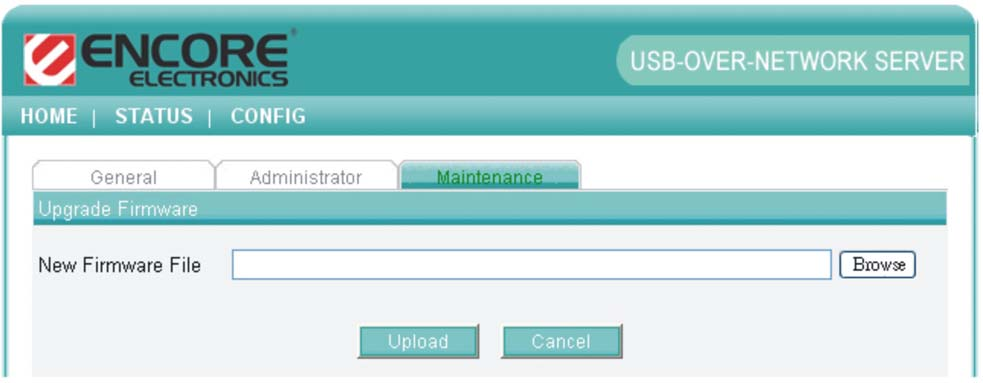
24 Maintenance If you want to restore factory default values of the ENNUS1 Server or upgrade new firmware, you can use the Maintenance tool. Restart: click Yes button to restart (reboot) the ENNUS1 Server. Factory Default: click this button, the ENNUS1 Server will restore factory default values. Download New Firmware: click this button to download new firmware from this product s public website. Firmware Upgrade: click Browse to find the firmware file to be upgraded. Click Upload to upload the firmware into the ENNUS1 Server. Please wait about 30 seconds for the upgrading. The ENNUS1 server will automatically reboot after the upgrading. 23
25 24
26 Chapter7 Troubleshooting This chapter provides useful information to help you resolve difficulties that you may experience with your ENNUS1 Server. Fault symptoms, possible causes, and remedial actions are provided within a quick reference table. This ENNUS1 Server s USB ports only support MFPs, printers, scanners, mass storage, and USB cameras. 7.1 LED Indicators Indicators Behavior Description Power On Power On Off Power off/system error Link Status USB 7.2 Firewall On Off Blinking Off On Blinking Off Network connected No physical connection to network Activity on network No activity on network USB device connected Connected USB device error No physical connection to USB device If firewall software has been installed on your PC, it may block the communication between the PC and the ENNUS1 server so that the ENNUS1 server cannot work properly. To solve this problem, either disable the firewall or configure the firewall to allow the following TCP and UDP ports: 7305, 7413,
 and password (default: admin). 3. Click Maintenance. 4. Click Factory Default. 5. Click Yes to confirm 8.")
27 Chapter8 Restore Factory Defaults You may restore the ENNUS1 Server s default parameters by one of the following methods. 8.1 Using the ENNUS1 Server s Web Pages 1. Go to the ENNUS1 Server s web page and click CONFIG 2. Enter administrator (default: admin) and password (default: admin). 3. Click Maintenance. 4. Click Factory Default. 5. Click Yes to confirm 8.2 Using Init Button Plug in the power adaptor while pressing the Init button until the USB LED blinks. After that, unplug the power adaptor and then plug in the power adapter again to restart the ENNUS1 server. The ENNUS1 server will now operate using the factory default values. 26
28 8.3 Default Parameters List Server Information Server Name: ENNUS1 TCP/IP Automatically get IP by DHCP: Enabled - Manual DNS: None (Disabled). Static IP: Disabled - IP Address: Subnet Mask: Default Gateway: none - DNS Server: none User Accounts Administrator: admin Password: admin 27

29 Chapter9 Upgrade Firmware This chapter describes how to upgrade firmware. Please follow one of the following methods: Method A: Using the ENNUS1 Server s Web Pages Please refer to section for details. Method B: Using the Init Button and the TFTP Client 1. Plug in the power adaptor while pressing the Init button until the USB LED blinks. Please note that after this step, the ENNUS1 Server will operate using the factory default values, i.e., your ENNUS1 Server s configuration will revert to factory default values. 2. Run the TFTP client Tool: Image Burner, from Windows Start menu. 3. Click Open Image to open your new firmware. Please note that you must configure your PC s TCP/IP such that PC and the ENNUS1 Server belong to the same LAN, e.g. PC s IP is xxx and subnet mask is Click Upload Image. 5. Wait for Image Uploading to finish and then click Close. 6. Unplug the power adapter and then plug in the power adapter to restart the ENNUS1 Server. 28
30 Chapter10 The Init Button The Init button is used for maintenance: Simultaneously press Init button and turn on (by plugging in the power adaptor) the ENNUS1 Server until the USB LED blinks. The ENNUS1 Server will now do the following tasks: A. Perform a factory reset of the ENNUS1 server, which restores most of the parameters and settings to factory default values. B. Perform a TFTP server. You can upgrade new firmware using any TFTP client tool. Note: After performing the tasks mentioned above, you have to unplug the power adaptor and then plug in the power adaptor to restart the ENNUS1 Server. Version 1.0 Copyright 2008 Encore Electronics, Inc. 29
USB 2.0 Multifunction Network Server
 USB 2.0 Multifunction Network Server DN-13020 DN-13021 DN-13022 DN-13023 User Manual DN-13020 DN-13021 DN-13022 DN-13023 1 Table of Contents CHAPTER1 PRODUCT OVERVIEW... 4 1.1 Package Contents... 4 1.2
Digitus DN-13007 / DN-13008 / DN-13018
 Digitus DN-13007 / DN-13008 / DN-13018 USB 2.0 Hi-Speed MFP Server Quick Installation Guide 1. Introduction This document describes the steps for installing and configuring Digitus DN-13007/DN-13008/DN-13018
Installation Guide Wireless 4-Port USB Sharing Station. GUWIP204 Part No. M1172-a
 Installation Guide Wireless 4-Port USB Sharing Station 1 GUWIP204 Part No. M1172-a 2011 IOGEAR. All Rights Reserved. PKG-M1172-a IOGEAR, the IOGEAR logo, MiniView, VSE are trademarks or registered trademarks
TL-PS310U Single USB 2.0 Port MFP and Storage Server
 TL-PS310U Single USB 2.0 Port MFP and Storage Server Rev: 2.0.0 1910010313 Contents Chapter 1 Introduction... 1 1.1 Product Overview...1 1.2 Network Management...1 1.3 Components and Features...1 1.4 Hardware
TDP43ME NetPS. Network Printer Server. Control Center. for Ethernet Module
 Panduit Corp. 2010 TDP43ME NetPS PA26306A01 Rev. 01 11-2010 Network Printer Server Control Center for Ethernet Module NOTE: In the interest of higher quality and value, Panduit products are continually
CMP-102U. Quick Installation Guide
 CMP-102U Quick Installation Guide V1.0 http://www.cnet.com.tw 1 CMP-102U Supports One High-speed USB2.0 Port MFP Server Supports 10/100Mbps Fast Ethernet Network Quick Installation Guide 1 Package Contents:
USER GUIDE. Ethernet Configuration Guide (Lantronix) P/N: 2900-300321 Rev 6
 P/N: 2900-300321 Rev 6") KRAMER ELECTRONICS LTD. USER GUIDE Ethernet Configuration Guide (Lantronix) P/N: 2900-300321 Rev 6 Contents 1 Connecting to the Kramer Device via the Ethernet Port 1 1.1 Connecting the Ethernet Port Directly
KRAMER ELECTRONICS LTD. USER GUIDE Ethernet Configuration Guide (Lantronix) P/N: 2900-300321 Rev 6 Contents 1 Connecting to the Kramer Device via the Ethernet Port 1 1.1 Connecting the Ethernet Port Directly
ENPS-MF1. 1 USB Port. Multifunctional Print Server. Quick Installation Guide V1.0
 ENPS-MF1 1 USB Port Multifunctional Print Server V1.0 Specifications or features are subject to change without prior notice. All brand names or trademarks are the property of their respective owners. Packing
LPT1 Printer Connector. External Power Supply Connector Power Indicator
 AXIS 1650 Set-up Instructions Page 3 Unpack box Verify that you have all the items listed below: LPT1 Printer Connector Network Indicator Ethernet Connector External Power Supply Connector Power Indicator
Network Setup Guide. Introduction. Setting up for use over LAN
 Network Setup Guide This manual contains the setup information required to use the machine over wired LAN. If you use the machine with USB connection, refer to your setup sheet. Introduction To use the
Easy Setup Guide for the Sony Network Camera
 -878-191-11 (1) Easy Setup Guide for the Sony Network Camera For setup, a computer running the Microsoft Windows Operating System is required. For monitoring camera images, Microsoft Internet Explorer
3.5 EXTERNAL NETWORK HDD. User s Manual
 3.5 EXTERNAL NETWORK HDD User s Manual Table of Content Before You Use Key Features H/W Installation Illustration of Product LED Definition NETWORK HDD Assembly Setup the Network HDD Home Disk Utility
Configuring NXT Hardware with Mercury Inside into Doors.NET TM Application Note
 1.0 Installing the Mercury SCP Gateway The MSC/SCP gateway must be installed to interface with Mercury hardware. This gateway must be chosen during the installation of the software, or it can be added
Chapter 1 Installing the Gateway
 Chapter 1 Installing the Gateway This chapter describes how to set up the wireless voice gateway on your Local Area Network (LAN), connect to the Internet, and perform basic configuration. For information
DN-13007. 2 USB 2.0 Hi-Speed Ports/MFP Server User`s Manual. Version 1.17
 DN-13007 2 USB 2.0 Hi-Speed Ports/MFP Server User`s Manual Version 1.17 1 Table of Contents CHAPTER1 INTRODUCTION...4 1.1 About this Manual...4 1.2 Support Services...4 CHAPTER2 PRODUCT OVERVIEW...4 2.1
Network/Floating License Installation Instructions
 Network/Floating License Installation Instructions Installation steps: On the Windows PC that will act as License Manager (SERVER): 1. Install HASP Run-time environment, SERVER 2. Plug in the red USB hardware
OUTDOOR IR NETWORK CAMERA Series
 OUTDOOR IR NETWORK CAMERA Series INSTALLATION GUIDE Please read instructions thoroughly before operation and retain it for future reference. 1. OVERVIEW 1.1 Package Content Network camera Installation
LabelWriter. Print Server. User Guide
 LabelWriter Print Server User Guide Copyright 2010 Sanford, L.P. All rights reserved. 08/10 No part of this document or the software may be reproduced or transmitted in any form or by any means or translated
The Wireless LAN (Local Area Network) USB adapter can be operated in one of the two following networking configurations :
 USB adapter can be operated in one of the two following networking configurations :") SAGEM Wi-Fi 11g USB ADAPTER Quick Start Guide About this guide This Quick Start Guide describes how to install and operate your SAGEM Wi-Fi 11g USB ADAPTER. Please read this manual before you install the
SAGEM Wi-Fi 11g USB ADAPTER Quick Start Guide About this guide This Quick Start Guide describes how to install and operate your SAGEM Wi-Fi 11g USB ADAPTER. Please read this manual before you install the
Phaser 3635MFP Software Upgrade Process
 Overview Phaser 3635MFP Software Upgrade Process The Software Upgrade feature allows the customer to upgrade the machine software as requested by a Xerox Customer Support Center Representative, without
Wireless LAN 802.11g USB Adapter
 Wireless LAN 802.11g USB Adapter User s Guide Version 1.0 User s Guide 0 Copyright statement No part of this publication may be reproduced, stored in a retrieval system, or transmitted in any form or by
Keri USB-A Connection and Configuration
 Step 1 - Connect the KPC-1 cable to the K-USB. NOTE: The form of the USB converter may vary, so the unit you receive may not be identical to the one displayed here. Step 2 Plug the USB Connector of the
You may refer the Quick Installation Guide in the package box for more information.
 Hardware Installation: 1. Turn off your modem. 2. Use one Ethernet cable to connect your modem to WAN port (Blue) port of BR-6228nC. 3. Use another Ethernet cable to connect your PC to one LAN Port (Yellow)
Chapter 10 Troubleshooting
 Chapter 10 Troubleshooting This chapter provides troubleshooting tips and information for your ProSafe Dual WAN Gigabit Firewall with SSL & IPsec VPN. After each problem description, instructions are provided
3.5 LAN HDD Enclosure User s Manual
 3.5 LAN HDD Enclosure User s Manual NOTE: 1. USB and LAN can t be used at the same time. 2. HDD should be formatted as FAT32. Please check Disk utility section in this manual. 3. For internet FTP usage,
ethernet connection For more information about the printer's ethernet feature, click the topic below: ethernet lights network configuration page
 ethernet table of contents ethernet connection The printer's built-in ethernet feature allows you to connect the printer directly to an ethernet network without the need for an external print server. For
P-660HWP-Dx. Quick Start Guide. 802.11g HomePlug AV ADSL2+ Gateway. Version 3.40 7/2007 Edition 1. Copyright 2007. All rights reserved.
 P-660HWP-Dx 802.11g HomePlug AV ADSL2+ Gateway Quick Start Guide Version 3.40 7/2007 Edition 1 Copyright 2007. All rights reserved. Overview The P-660HWP-Dx is a gateway which combines high-speed ADSL
TE100-P21/TEW-P21G Windows 7 Installation Instruction
 Hardware Installation TE100-P21/TEW-P21G Windows 7 Installation Instruction 1. Go to http://www.trendnet.com/downloads/ to download the Windows 7 Utility. Save the file to your desktop. 2. Right click
1-Port Wireless USB 2.0 Print Server Model # APSUSB201W. Quick Installation Guide. Ver. 2A
 1-Port Wireless USB 2.0 Print Server Model # APSUSB201W Quick Installation Guide Ver. 2A Section 1 Step 1Connect one end of the Ethernet cable to the RJ-45 port of the Print Server and attach the other
Router Setup Manual. NETGEAR, Inc. 4500 Great America Parkway Santa Clara, CA 95054 USA 208-10060-01 2006-03-17
 NETGEAR, Inc. 4500 Great America Parkway Santa Clara, CA 95054 USA 208-10060-01 2006-03-17 2006 by NETGEAR, Inc. All rights reserved. Trademarks NETGEAR is a trademark of Netgear, Inc. Microsoft, Windows,
HW550-3G. 3G Mobile Broadband plus 4-Port Wireless-N Router
 HW550-3G 3G Mobile Broadband plus 4-Port Wireless-N Router Table of Contents About the Product...4 Features...5 Requirements...6 Package Content...7 Device Design...8 Getting Started...11 Plan Your Network...12
User s Manual. Copyright 2010 Vantec Thermal Technologies. All Rights Reserved.
 Copyright 2010 Vantec Thermal Technologies. All Rights Reserved. User s Manual Package Contents: 1 NextStar FX Gigabit NAS Adapter x1 2 AC Adapter x1 3 Installation Guide x1 4 Rubber Feet x4 5 User s CD
Ethernet Interface Manual Thermal / Label Printer. Rev. 1.01 Metapace T-1. Metapace T-2 Metapace L-1 Metapace L-2
 Ethernet Interface Manual Thermal / Label Printer Rev. 1.01 Metapace T-1 Metapace T-2 Metapace L-1 Metapace L-2 Table of contents 1. Interface setting Guiding...3 2. Manual Information...4 3. Interface
Wireless Presentation System User s Manual
 Wireless Presentation System User s Manual (Model Name: WPS-Dongle) Version: 3.0 Date: August 19, 2009 Table of Contents 1. Overview...3 2. Quick Start...4 3. Windows Client Utility...7 3.1 Starting Program...7
Section 5: Installing the Print Driver
 Section 5: Installing the Print Driver In This Section Print Driver Installation for USB Connection Using the Ethernet Connection and a Crossover Cable Print Driver: The Epilog print driver is the software
Deployment Guide: Transparent Mode
 Deployment Guide: Transparent Mode March 15, 2007 Deployment and Task Overview Description Follow the tasks in this guide to deploy the appliance as a transparent-firewall device on your network. This
ADSL X5 U S E R S G U I D E
 ADSL X5 U S E R S G U I D E NOTICE This document contains proprietary information protected by copyright, and this Manual and all the accompanying hardware, software, and documentation are copyrighted.
User Manual. EtherUSB
 User Manual EtherUSB USB Ethernet Access Point for PDA V 2.0 Clarinet Systems, Inc. Clarinet Systems, Inc. http://www.clarinetsys.com Page 1 Publication Revision No. Control Table Rev. No. Date Contents
3.5 Mobile LAN Disk. User Guide
 3.5 Mobile LAN Disk User Guide Contents 1. Hardware...2 1.1 Power...2 1.2 Ports...2 1.3 Reset Button...2 1.4 LEDs...2 1.5 Front View...3 1.6 Rear View...3 2. Installation....... 4 2.1 Requirements 4 2.2
RouteFinder SOHO. Quick Start Guide. SOHO Security Appliance. EDGE Models RF825-E, RF825-E-AP CDMA Models RF825-C-Nx, RF825-C-Nx-AP
 RouteFinder SOHO SOHO Security Appliance EDGE Models RF825-E, RF825-E-AP CDMA Models RF825-C-Nx, RF825-C-Nx-AP Quick Start Guide RouteFinder RF825 Series Quick Start Guide RouteFinder SOHO Security Appliance
ADSL Router Quick Installation Guide Revised, edited and illustrated by Neo
 ADSL Router Quick Installation Guide Revised, edited and illustrated by Neo A typical set up for a router PCs can be connected to the router via USB or Ethernet. If you wish to use a telephone with the
Network Storage Link
 A Division of Cisco Systems, Inc. WIRED Network Storage Link for USB 2.0 Disk Drives User Guide Model No. NSLU2 Copyright and Trademarks Specifications are subject to change without notice. Linksys is
N300 WiFi Range Extender WN2000RPT User Manual
 N300 WiFi Range Extender WN2000RPT User Manual December 2013 202-11333-01 350 East Plumeria Drive San Jose, CA 95134 USA Support Thank you for selecting NETGEAR products. After installing your device,
Ultra Thin Client TC-401 TC-402. Users s Guide
 Ultra Thin Client TC-401 TC-402 Users s Guide CONTENT 1. OVERVIEW... 3 1.1 HARDWARE SPECIFICATION... 3 1.2 SOFTWARE OVERVIEW... 4 1.3 HARDWARE OVERVIEW...5 1.4 NETWORK CONNECTION... 7 2. INSTALLING THE
Print Server Application Guide. This guide applies to the following models.
 Print Server Application Guide This guide applies to the following models. TL-WR842ND TL-WR1042ND TL-WR1043ND TL-WR2543ND TL-WDR4300 CONTENTS Chapter 1. Overview... 1 Chapter 2. Before Installation...
MFC7840W Windows Network Connection Repair Instructions
 Difficulty printing from your PC can occur for various reasons. The most common reason a networked Brother machine may stop printing, is because the connection between the computer and the Brother machine
TL-PS310U Single USB 2.0 Port MFP and Storage Server
 Single USB 2.0 Port MFP and Storage Server REV3.0.0 1910010947 COPYRIGHT & TRADEMARKS Specifications are subject to change without notice. is a registered trademark of TP-LINK TECHNOLOGIES CO., LTD. Other
Software Installation Guide
 Software Installation Guide This manual explains how to install the software over a USB or network connection. Network connection is not available for models SP 200/200S/203S/203SF/204SF. To manually configure
The following sections describe the Gateway configuration pages in the SBG1000 Setup Program.
 Configuration Gateway > WAN Page Gateway: LAN nat config Page Gateway: LAN dhcp server config Page Gateway LOG Page Preparing the Network Preparing the Computers for TCP/IP Networking Configuring TCP/IP
Section 5: Connecting the Laser to Your Computer
 Section 5: Connecting the Laser to Your Computer In This Section Connecting the Laser to your Computer USB Port Ethernet Port Connecting the Laser to Your Computer All Epilog systems are designed to be
Movie Cube. User s Guide to Wireless Function
 Movie Cube User s Guide to Wireless Function Table of Contents 1. WLAN USB Adapter Connection...3 2. Wireless Setup...4 2.1 Infrastructure (AP)...5 2.2 Peer to Peer (Ad Hoc)...7 2.3 Settings for PC...8
DSL Installation Guide
 DSL Installation Guide Thank you for choosing Integra Telecom s DSL service! Introduction This guide will walk you through the DSL installation process and will help you configure a computer to access
EVA Drivers 6.1 and TWAIN Installation Guide for EVA Classic Digital Sensors
 8 Westchester Plaza, Suite 112, Elmsford, NY 10523 (914) 592-6100 Fax (914) 592-6148 www.imageworkscorporation.com EVA Drivers 6.1 and TWAIN Installation Guide for EVA Classic Digital Sensors Note: This
Additional Requirements for ARES-G2 / RSA-G2. One Ethernet 10 Base T/100 Base TX network card required for communication with the instrument.
 TA Instruments TRIOS Software Installation Instructions Installation Requirements Your TRIOS Instrument Control software includes all the components necessary to install or update the TRIOS software, as
Configuring the WT-4 for Upload to a Computer (Ad-hoc Mode)
") En Configuring the WT-4 for Upload to a Computer (Ad-hoc Mode) Windows XP This document provides basic instructions on configuring the WT-4 wireless transmitter and a Windows XP Professional SP2 computer
En Configuring the WT-4 for Upload to a Computer (Ad-hoc Mode) Windows XP This document provides basic instructions on configuring the WT-4 wireless transmitter and a Windows XP Professional SP2 computer
PePWave Surf Series PePWave Surf Indoor Series: Surf 200, AP 200, AP 400
 PePWave Surf Series PePWave Surf Indoor Series: Surf 200, AP 200, AP 400 PePWave Surf Outdoor Series: Surf AP 200/400-X, PolePoint 400-X, Surf 400-DX User Manual Document Rev. 1.2 July 07 COPYRIGHT & TRADEMARKS
WRE6505. User s Guide. Quick Start Guide. Wireless AC750 Range Extender. Default Login Details. Version 1.00 Edition 1, 4 2014
 WRE6505 Wireless AC750 Range Extender Version 1.00 Edition 1, 4 2014 2.4G 5G Quick Start Guide User s Guide Default Login Details LAN IP Address 192.168.1.2 User Name admin www.zyxel.com Password 1234
Print Server Application Guide
 Print Server Application Guide TD W8968 TD W8970 / TD W8970B TD W8980 / TD W8980B Rev: 1.0.0 1910010772 Contents Overview...1 Installation for Windows OS...2 Application for Windows OS...7 How to launch/exit
To perform Ethernet setup and communication verification, first perform RS232 setup and communication verification:
 PURPOSE Verify that communication is established for the following products programming option (488.2 compliant, SCPI only): DCS - M9C & DCS M130, DLM M9E & DLM-M9G & DLM M130, DHP - M9D, P series, SG,
Quick Installation Guide
 V48.01 Model: FI8919W Quick Installation Guide Outdoor Pan/Tilt Wireless IP Camera For Windows OS ------- Page 1 For MAC OS ------- Page 15 ShenZhen Foscam Intelligent Technology Co., Ltd Quick Installation
Zebra Ethernet. Frequently Asked Questions
 Zebra Ethernet Frequently Asked Questions Zebra Technologies Corporation Card Imaging Division 1001 Flynn Road Camarillo, CA 93012 USA Phone: (805) 579-1800 Fax: (805) 579-1808 www.cards.zebra.com 2004
NETVIGATOR Wireless Modem Setup Guide. (TG789Pvn)
") NETVIGATOR Wireless Modem Setup Guide (TG789Pvn) Configure the NETVIGATOR Wireless Modem Make sure that system meets the following requirement prior to NETVIGATOR Wireless Modem usage: - Subscribers who
NETVIGATOR Wireless Modem Setup Guide (TG789Pvn) Configure the NETVIGATOR Wireless Modem Make sure that system meets the following requirement prior to NETVIGATOR Wireless Modem usage: - Subscribers who
Windows Vista /Windows 7 Installation Guide
 Windows Vista / 7 Installation Guide Before you can use the machine, you must set up the hardware and install the driver. Please read the Quick Setup Guide and this Windows Vista / 7 Installation Guide
PREFACE http://www.okiprintingsolutions.com 07108001 iss.01 -
 Network Guide PREFACE Every effort has been made to ensure that the information in this document is complete, accurate, and up-to-date. The manufacturer assumes no responsibility for the results of errors
AXIS 205 Network Camera Quick Installation Guide
 AXIS 205 Quick Installation Guide Page 1 of 6 AXIS 205 Network Camera Quick Installation Guide Focus Ring Status Indicator (surrounding the focus ring) Serial number Network Indicator Control Button Power
Allworx Installation Course
 VPN Hello and welcome. In the VPN section we will cover the steps for enabling the VPN feature on the Allworx server and how to set up a VPN connection to the Allworx System from your PC. Page 1 VPN The
Connecting to the Internet
 Connecting to the Internet Connecting the Gateway to the Internet Configuration of TCP/IP Protocol Installing the USB Drivers Connecting Ethernet Network Devices Connecting USB Network Devices Connecting
USB 2.0 4-PORT NETWORK HUB. User Manual DA-70251 DA-70252 1
 USB 2.0 4-PORT NETWORK HUB User Manual DA-70251 DA-70252 1 Copyright Notice Copyright DIGITUS 2010. All rights reserved. Disclaimer DIGITUS shall not be liable for technical or editorial errors or omissions
Network Scanner Tool V3.5. User s Guide Version 3.5.01
 Network Scanner Tool V3.5 User s Guide Version 3.5.01 Copyright 2000-2016 by SHARP CORPORATION. All rights reserved. Reproduction, adaptation or translation without prior written permission is prohibited,
Software Installation Guide
 Software Installation Guide This manual explains how to install the software over a USB or network connection. Network connection is not available for models SP 200/200S/203S/203SF/204SF. Flowchart The
Two options are available to install the device: 1. Conceptronic USB Filetransfer Cable (*) 2. Conceptronic USB Network Filetransfer (*)
 2. Conceptronic USB Network Filetransfer (*)") Conceptronic CBRIDGE20 USER S MANUAL Two options are available to install the device: 1. Conceptronic USB Filetransfer Cable (*) 2. Conceptronic USB Network Filetransfer (*) During the installation you
Conceptronic CBRIDGE20 USER S MANUAL Two options are available to install the device: 1. Conceptronic USB Filetransfer Cable (*) 2. Conceptronic USB Network Filetransfer (*) During the installation you
EASE Scan Tool Customers. SECTION I - Installation
 Please Install Your EASE Scan Tool DVD Before Installing Any Other Software That Came With Your Package. SECTION I - Installation ATTENTION: Do NOT connect an EASE Vehicle Interface Device to your Computer
Connecting to the Internet. LAN Hardware Requirements. Computer Requirements. LAN Configuration Requirements
 Connecting to the Internet LAN Hardware Requirements Computer Requirements LAN Configuration Requirements Installation Performed by Time Warner Cable Technician Connecting via Ethernet Connecting via USB
Configuring an A Series LED Sign Controller for your Network
 Configuring an A Series LED Sign Controller for your Network A Series LED displays from Optec support both serial and 10BaseT Ethernet communication. Serial communication via RS232 or RS485 is independent
Quick Start Guide NVR DS-7104NI-SL/W NVR. www.hikvision.com. First Choice For Security Professionals
 Quick Start Guide NVR DS-7104NI-SL/W NVR NOTE: For more detailed information, refer to the User s Manual on the CD-ROM. You must use your PC or MAC to access the files. www.hikvision.com Quick Start 1.
How do I configure the wireless printer using a USB or Ethernet cable and install the printer driver in Windows?
 How do I configure the wireless printer using a USB or Ethernet cable and install the printer driver in Windows? STEP I: Gather the wireless network settings of your wireless access point or wireless router
FreeAgent DockStar Network Adapter User Guide
 FreeAgent DockStar Network Adapter User Guide FreeAgent DockStar Network Adapter User Guide 2010 Seagate Technology LLC. All rights reserved. Seagate, Seagate Technology, the Wave logo, and FreeAgent are
c. Securely insert the Ethernet cable from your cable or DSL modem into the Internet port (B) on the WGT634U. Broadband modem
 on the WGT634U. Broadband modem") Start Here Follow these instructions to set up your router. Verify That Basic Requirements Are Met Assure that the following requirements are met: You have your broadband Internet service settings handy.
Start Here Follow these instructions to set up your router. Verify That Basic Requirements Are Met Assure that the following requirements are met: You have your broadband Internet service settings handy.
Fiery E100 Color Server. Welcome
 Fiery E100 Color Server Welcome 2011 Electronics For Imaging, Inc. The information in this publication is covered under Legal Notices for this product. 45098226 27 June 2011 WELCOME 3 WELCOME This Welcome
User Manual Network Interface
 User Manual Network Interface Rev. 1.00 SRP-350plusll SRP-352plusll http://www.bixolon.com Table of Contents 1. Manual Information...3 2. Specifications...3 2-1 Hardware version...3 2-2 Configuration Tool...3
Windows 2000/XP Network
 This section provides installation and troubleshooting steps for Windows 2000/XP: Preliminary steps see page 23. Quick CD-ROM install steps see page 23. Other methods of installation see page 24. Quick
Network Scanner Tool R3.1. User s Guide Version 3.0.04
 Network Scanner Tool R3.1 User s Guide Version 3.0.04 Copyright 2000-2004 by Sharp Corporation. All rights reserved. Reproduction, adaptation or translation without prior written permission is prohibited,
4-441-095-12 (1) Network Camera
 Network Camera") 4-441-095-12 (1) Network Camera SNC easy IP setup Guide Software Version 1.0 Before operating the unit, please read this manual thoroughly and retain it for future reference. 2012 Sony Corporation Table
4-441-095-12 (1) Network Camera SNC easy IP setup Guide Software Version 1.0 Before operating the unit, please read this manual thoroughly and retain it for future reference. 2012 Sony Corporation Table
N300 Wireless Gigabit Router Setup Manual
 N300 Wireless Gigabit Router Setup Manual NETGEAR, Inc. 350 E. Plumeria Drive San Jose, CA 95134 USA June 2010 208-10443-03 v1.0 2010 by NETGEAR, Inc. All rights reserved. Trademarks NETGEAR and the NETGEAR
USB VoIP Phone Adapter. User s Manual
 USB VoIP Phone Adapter User s Manual FCC Certifications This Equipment has been tested and found to comply with the limits for a Class B digital device, pursuant to part 15 and part 68 of the FCC Rules.
1. Hardware Installation
 4 Port 10/100M Internet Broadband Router with USB Printer server Quick Installation Guide #4824904AXZZ0 1. Hardware Installation A. System Requirement Before you getting started, make sure that you meet
NXT Controller Manual IP Assignment in WAN Environments Application Note
 It is difficult to perform NXT controller IP address assignment and auto-configuration when controllers are on different subnets from the local PC (the PC from which the Doors.NET client is run). This
BASIC INSTRUCTIONS TO CONFIGURE ZYXEL P8701T CPE USING THE WEB INTERFACE
 BASIC INSTRUCTIONS TO CONFIGURE ZYXEL P8701T CPE USING THE WEB INTERFACE 12/11/2012 Index 1 INTRODUCTION... 1-1 2 FACTORY DEFAULT SETTINGS... 2-1 3 CPE BASIC OPERATIONS... 3-1 3.1 PASSWORD MODIFICATION...
S-SupremaConfigurationGuide-DOC 7/23/2014. Suprema Biometrics Configuration Guide ACS OnSite Aparato
 S-SupremaConfigurationGuide-DOC 7/23/2014 Suprema Biometrics Configuration Guide ACS OnSite Aparato Page 2 Suprema Configuration Guide ACS OnSite Aparato Table of Contents 1. SUPREMA BIOSTAR CONFIGURATION...
Wireless Presentation Adaptor User s Manual
 Wireless Presentation Adaptor User s Manual (Model Name: WPS-Dongle 2) Version: 2.0 Date: Apr. 28, 2011 1 Table of Contents 1. Overview... 4 2. Quick Start... 6 3. Windows Client Utility... 9 3.1 Starting
SATO Network Interface Card Configuration Instructions
 SATO Network Interface Card Configuration Instructions Table of Contents 1. Reset of wired/wireless interface card... 3 2. Installing the All-In-One Utility (recommended)... 4 3. Configuring wired/wireless
NAS SERVER FOR EXTERNAL HDD
 NAS SERVER FOR EXTERNAL HDD Quick Installation Guide DN-70230 System requirement Operating system and software: Windows 2000, XP, 2003, Vista, Mac OS X or above, Linux Required hardware resources: 10/100
Intel Active Management Technology with System Defense Feature Quick Start Guide
 Intel Active Management Technology with System Defense Feature Quick Start Guide Introduction...3 Basic Functions... 3 System Requirements... 3 Configuring the Client System...4 Intel Management Engine
Router Setup Manual. NETGEAR, Inc. 4500 Great America Parkway Santa Clara, CA 95054 USA. October 2007 208-10146-01 v1.0
 NETGEAR, Inc. 4500 Great America Parkway Santa Clara, CA 95054 USA October 2007 208-10146-01 v1.0 Trademarks NETGEAR and the NETGEAR logo are registered trademarks, and RangeMax and Smart Wizard are trademarks
HomePlug Turbo Powerline Ethernet Bridge. User Manual
 HomePlug Turbo Powerline Ethernet Bridge User Manual Copyright The contents of this publication may not be reproduced in any part of as a whole, stored, transcribed in an information retrieval system,
Type Message Description Probable Cause Suggested Action. Fan in the system is not functioning or room temperature
 Table of Content Error Messages List... 2 Troubleshooting the Storage System... 3 I can t access the Manager... 3 I forgot the password for logging in to the Manager... 3 The users can t access the shared
Networking. General networking. Networking overview. Common home network configurations. Wired network example. Wireless network examples
 Networking General networking Networking overview A network is a collection of devices such as computers, printers, Ethernet hubs, wireless access points, and routers connected together for communication
ASUS WL-5XX Series Wireless Router Internet Configuration. User s Guide
 ASUS WL-5XX Series Wireless Router Internet Configuration User s Guide Contents Chapter 1 Introduction:...1 Chapter 2 Connecting the wireless router...1 Chapter 3 Getting to know your Internet connection
MAGPOWR Spyder Firmware Update Instruction Manual
 MAGPOWR TENSION CONTROL MAGPOWR Spyder Firmware Update Instruction Manual EN Spyder and Spyder-Plus MI 850A324 B COPYRIGHT All of the information herein is the exclusive proprietary property of Maxcess
3.5 Mobile LAN Disk User Guide
 3.5 Mobile LAN Disk User Guide A new, unformatted HDD must be initialized before LAN operation. Via LAN connection, format HDD under administrator s user interface before use Refer to Nettool Quick Installation