In this lecture: Lecture 5: Logic Simplification & Karnaugh Maps
|
|
|
- Justina Owens
- 7 years ago
- Views:
Transcription
1 In this lecture: Lecture 5: Logic Simplification & Karnaugh Maps Dr Pete Sedcole Department of E&E Engineering Imperial College London (Floyd ) (Tocci ) Standard form of Boolean Expression: Sum-of-Products & Product-of-Sums (SOP/POS) Canonical form Boolean simplification with Boolean algebra Boolean simplification with Karnaugh Maps The Don t care logic state E.2 Digital Electronics 5. 3 October 28 E.2 Digital Electronics October 28 Forms of Boolean Expressions Sum-of-products (SOP) e.g.: + DEF + AEF the product (AND) terms are formed first, then summed (OR) Product-of-sums (POS) e.g.: Y (A+B+E)(C+D+E)(B+F) the sum (OR) terms are formed first, then the product (AND) It is possible to convert between the two forms using DeMorgan s theorems. E.2 Digital Electronics October 28 Canonical form In the canonical form of a Boolean expression, every variable appears in every term e.g.: f ( A, B, C, D) D + D + D Canonical form is not an efficient way of writing the Boolean expression, but is useful sometimes in design and analysis E.2 Digital Electronics October 28
2 How do we find the canonical form of an expression? Start with the SOP (sum-of-products) form AND each incomplete expression with + where is the missing variable e.g.: f ( A, B, C) AB + BC AB( C + C ) + ( A + A) BC The product term in a canonical SOP expression is called a minterm E.2 Digital Electronics October 28 Canonical form and notation Construct the truth table for the function f ( A, B, C) + + Row number A An alternative notation: write f as a sum of the row numbers that have TRUE minterms: E.2 Digital Electronics October 28 B f (3,6,7) C f Simplifying logic circuits Method : Minimisation by Boolean Algebra Obtain the expression of the circuit s function, then try to simplify We will look at two methods: Algebraic and Karnaugh maps E.2 Digital Electronics October 28 Make use of rules and theorems of Boolean algebra to simplify the Boolean expression Try to reduce the complexity of the equation, so that the circuit is also less complex This method relies on your algebraic skill Three things you can try E.2 Digital Electronics October 28
3 Given: Write it as Then apply Minimised form: Tool : Grouping A + AB + A (+ B) + BC BC ( + B) A + BC Tool 2: ANDing with redundant logic ANDing an expression with ( + ) or ( + ) does not alter the logic ANDing then expanding may enable an expression to be simplified Example: AB + AC + BC AB( C + C ) + AC + BC + + AC + BC BC( + A) + AC ( + B) BC + AC E.2 Digital Electronics October 28 E.2 Digital Electronics 5. 3 October 28 Tool 3: DeMorgan s Theorems Example of logic design Inversions of compound expressions can be simplified using DeMorgan s Theorems Example: + ACD + BC ( A + B + C ) + ( A + C + D) + BC A + B + C + D + BC A + B + C + D D E.2 Digital Electronics 5. 3 October 28 Design a logic circuit having three inputs (A, B, C) that will have its output HIGH only when a majority of the inputs are HIGH Step : Draw the truth table Step 2: Write the product terms for each case where the output is A E.2 Digital Electronics October 28 B C Z
 BC + AC + AB E.2 Digital Electronics 5.3 3 October 28 E.2 Digital Electronics 5.4 3 October 28 Minimisation using Karnaugh Maps What is a Karnaugh map?")
 Squares at the edges are adjacent to squares on the opposite edges Corresponds to minterm An example with 4 variables: AB\CD The square marked?")
4 Step 3: Write the SOP form for the output Step 5: Implement the circuit Z Step 4: Using the rules of Boolean algebra, try to simplify the expression Z BC( A + A) + AC( B + B) + AB( C + C ) BC + AC + AB E.2 Digital Electronics October 28 E.2 Digital Electronics October 28 Minimisation using Karnaugh Maps What is a Karnaugh map? A grid of squares An example with three variables: A BC Similar to a truth table: shows the output value for every combination of inputs Each square represents a minterm Only one variable changes between adjacent squares (similar to Gray Codes) Squares at the edges are adjacent to squares on the opposite edges Corresponds to minterm An example with 4 variables: AB\CD The square marked? represents:??? The square marked?? represents: Note that they differ only in the C variable D D E.2 Digital Electronics October 28 E.2 Digital Electronics October 28
5 Filling out a Karnaugh Map Write the Boolean expression in SOP form For each product term, write a in all the squares which are included in the term Write a in the remaining blank squares Example: + + AB A \ BC Minimisation technique Minimisation is done by spotting patterns of s and s The rules of algebra can be used to describe the patterns in simple product terms For example, take a pair of adjacent s: Adjacent squares differ by one variable The expression for a pair of adjacent s has the form: ( P ) C + ( P) C ( P)( C + C ) This can be simplified to just P E.2 Digital Electronics October 28 E.2 Digital Electronics October 28 The example from an earlier slide: A \ BC The adjacent squares and differ only in A Therefore they can be combined into just BC Normally we draw boxes around the squares to be combined + + AB A \ BC Cover all the s with the largest groups The simplified Boolean expression is found by summing all the terms corresponding to each group AC + BC + AB Can do this for larger groups of s (of 4, 8, ) E.2 Digital Electronics October 28 E.2 Digital Electronics October 28


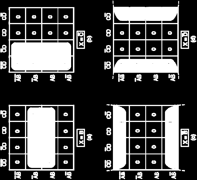
6 More examples of grouping AB\CD AB\CD AB + C D B D + E.2 Digital Electronics October 28 E.2 Digital Electronics October 28 E.2 Digital Electronics October 28 E.2 Digital Electronics October 28
 all groups must be of size, 2, 4, 8, 6,. Construct the K-map and place s and s in the squares according to the SOP expression or truth table 2.")

7 K-map simplification Complete K-map simplification process Goal: find the form of a Boolean expression with the minimum number of product terms Method: group together s on a K-map Constraints: all s must be part of a group (even if it is a single group) all groups must be of size, 2, 4, 8, 6,. Construct the K-map and place s and s in the squares according to the SOP expression or truth table 2. Find the largest grouping of s that are not already all in a group; if there is more than one possibility, choose a grouping that minimises the total number of groups 3. Repeat step 2 until only isolated s remain 4. Form single groups of the remaining isolated s 5. Find the product term that corresponds to each group 6. OR together all the product terms E.2 Digital Electronics October 28 E.2 Digital Electronics October 28 Don t Care conditions In certain cases some input combinations may never occur, or the output doesn t matter when they do In this case we fill in the truth table / K-map with an means don t care (it is not a Boolean variable) acts like a joker or wildcard it can be either a or a depending on which value will help the minimisation Example: can be or, but the best minimisation is if A \ BC Z B E.2 Digital Electronics October 28 E.2 Digital Electronics October 28


8 More don t care examples Open the lift doors when the lift is stopped at a floor F2 F3 F2 F3 F2 F3 F2 F3 M F M F M F OPEN MF+ MF2 + MF3 M F E.2 Digital Electronics October 28 E.2 Digital Electronics October 28 The Karnaugh map of 5 variables K-map method summary AB\CD AB\CD E E Compared to algebraic manipulation, the K-map method is a more structured process requiring a fixed number of steps K-maps always produce a minimum expression The minimum expression is in general NOT unique For circuits with a large number of inputs (more than 4) other, more complex techniques must be used E.2 Digital Electronics October 28 E.2 Digital Electronics October 28
9 Summary SOP and POS are useful forms of Boolean equations Designing a combinational logic circuit:. Construct a truth table 2. Convert it to SOP 3. Simplify using Boolean algebra or a K-map 4. Implement A Karnaugh map is a graphical method for representing and simplifying Boolean expressions Don t care entries in a K-map can take values of or depending on which value is more helpful in the simplification E.2 Digital Electronics October 28
BOOLEAN ALGEBRA & LOGIC GATES
 BOOLEAN ALGEBRA & LOGIC GATES Logic gates are electronic circuits that can be used to implement the most elementary logic expressions, also known as Boolean expressions. The logic gate is the most basic
Karnaugh Maps & Combinational Logic Design. ECE 152A Winter 2012
 Karnaugh Maps & Combinational Logic Design ECE 52A Winter 22 Reading Assignment Brown and Vranesic 4 Optimized Implementation of Logic Functions 4. Karnaugh Map 4.2 Strategy for Minimization 4.2. Terminology
CSE140: Midterm 1 Solution and Rubric
 CSE140: Midterm 1 Solution and Rubric April 23, 2014 1 Short Answers 1.1 True or (6pts) 1. A maxterm must include all input variables (1pt) True 2. A canonical product of sums is a product of minterms
CSEE 3827: Fundamentals of Computer Systems. Standard Forms and Simplification with Karnaugh Maps
 CSEE 3827: Fundamentals of Computer Systems Standard Forms and Simplification with Karnaugh Maps Agenda (M&K 2.3-2.5) Standard Forms Product-of-Sums (PoS) Sum-of-Products (SoP) converting between Min-terms
Simplifying Logic Circuits with Karnaugh Maps
 Simplifying Logic Circuits with Karnaugh Maps The circuit at the top right is the logic equivalent of the Boolean expression: f = abc + abc + abc Now, as we have seen, this expression can be simplified
Chapter 2: Boolean Algebra and Logic Gates. Boolean Algebra
 The Universit Of Alabama in Huntsville Computer Science Chapter 2: Boolean Algebra and Logic Gates The Universit Of Alabama in Huntsville Computer Science Boolean Algebra The algebraic sstem usuall used
Boolean Algebra Part 1
 Boolean Algebra Part 1 Page 1 Boolean Algebra Objectives Understand Basic Boolean Algebra Relate Boolean Algebra to Logic Networks Prove Laws using Truth Tables Understand and Use First Basic Theorems
Digital Logic Design. Basics Combinational Circuits Sequential Circuits. Pu-Jen Cheng
 Digital Logic Design Basics Combinational Circuits Sequential Circuits Pu-Jen Cheng Adapted from the slides prepared by S. Dandamudi for the book, Fundamentals of Computer Organization and Design. Introduction
1. True or False? A voltage level in the range 0 to 2 volts is interpreted as a binary 1.
 File: chap04, Chapter 04 1. True or False? A voltage level in the range 0 to 2 volts is interpreted as a binary 1. 2. True or False? A gate is a device that accepts a single input signal and produces one
Karnaugh Maps. Circuit-wise, this leads to a minimal two-level implementation
 Karnaugh Maps Applications of Boolean logic to circuit design The basic Boolean operations are AND, OR and NOT These operations can be combined to form complex expressions, which can also be directly translated
Introduction. The Quine-McCluskey Method Handout 5 January 21, 2016. CSEE E6861y Prof. Steven Nowick
 CSEE E6861y Prof. Steven Nowick The Quine-McCluskey Method Handout 5 January 21, 2016 Introduction The Quine-McCluskey method is an exact algorithm which finds a minimum-cost sum-of-products implementation
Boolean Algebra (cont d) UNIT 3 BOOLEAN ALGEBRA (CONT D) Guidelines for Multiplying Out and Factoring. Objectives. Iris Hui-Ru Jiang Spring 2010
 UNIT 3 BOOLEAN ALGEBRA (CONT D) Guidelines for Multiplying Out and Factoring. Objectives. Iris Hui-Ru Jiang Spring 2010") Boolean Algebra (cont d) 2 Contents Multiplying out and factoring expressions Exclusive-OR and Exclusive-NOR operations The consensus theorem Summary of algebraic simplification Proving validity of an
Boolean Algebra (cont d) 2 Contents Multiplying out and factoring expressions Exclusive-OR and Exclusive-NOR operations The consensus theorem Summary of algebraic simplification Proving validity of an
Gates, Circuits, and Boolean Algebra
 Gates, Circuits, and Boolean Algebra Computers and Electricity A gate is a device that performs a basic operation on electrical signals Gates are combined into circuits to perform more complicated tasks
Digital circuits make up all computers and computer systems. The operation of digital circuits is based on
 Digital Logic Circuits Digital circuits make up all computers and computer systems. The operation of digital circuits is based on Boolean algebra, the mathematics of binary numbers. Boolean algebra is
Lecture 5: Gate Logic Logic Optimization
 Lecture 5: Gate Logic Logic Optimization MAH, AEN EE271 Lecture 5 1 Overview Reading McCluskey, Logic Design Principles- or any text in boolean algebra Introduction We could design at the level of irsim
United States Naval Academy Electrical and Computer Engineering Department. EC262 Exam 1
 United States Naval Academy Electrical and Computer Engineering Department EC262 Exam 29 September 2. Do a page check now. You should have pages (cover & questions). 2. Read all problems in their entirety.
2.0 Chapter Overview. 2.1 Boolean Algebra
 Thi d t t d ith F M k 4 0 2 Boolean Algebra Chapter Two Logic circuits are the basis for modern digital computer systems. To appreciate how computer systems operate you will need to understand digital
Binary Adders: Half Adders and Full Adders
 Binary Adders: Half Adders and Full Adders In this set of slides, we present the two basic types of adders: 1. Half adders, and 2. Full adders. Each type of adder functions to add two binary bits. In order
CH3 Boolean Algebra (cont d)
") CH3 Boolean Algebra (cont d) Lecturer: 吳 安 宇 Date:2005/10/7 ACCESS IC LAB v Today, you ll know: Introduction 1. Guidelines for multiplying out/factoring expressions 2. Exclusive-OR and Equivalence operations
CH3 Boolean Algebra (cont d) Lecturer: 吳 安 宇 Date:2005/10/7 ACCESS IC LAB v Today, you ll know: Introduction 1. Guidelines for multiplying out/factoring expressions 2. Exclusive-OR and Equivalence operations
Karnaugh Maps (K-map) Alternate representation of a truth table
 Alternate representation of a truth table") Karnaugh Maps (K-map) lternate representation of a truth table Red decimal = minterm value Note that is the MS for this minterm numbering djacent squares have distance = 1 Valuable tool for logic minimization
Karnaugh Maps (K-map) lternate representation of a truth table Red decimal = minterm value Note that is the MS for this minterm numbering djacent squares have distance = 1 Valuable tool for logic minimization
Unit 3 Boolean Algebra (Continued)
") Unit 3 Boolean Algebra (Continued) 1. Exclusive-OR Operation 2. Consensus Theorem Department of Communication Engineering, NCTU 1 3.1 Multiplying Out and Factoring Expressions Department of Communication
Unit 3 Boolean Algebra (Continued) 1. Exclusive-OR Operation 2. Consensus Theorem Department of Communication Engineering, NCTU 1 3.1 Multiplying Out and Factoring Expressions Department of Communication
Boolean Algebra. Boolean Algebra. Boolean Algebra. Boolean Algebra
 2 Ver..4 George Boole was an English mathematician of XIX century can operate on logic (or Boolean) variables that can assume just 2 values: /, true/false, on/off, closed/open Usually value is associated
CSE140: Components and Design Techniques for Digital Systems
 CSE4: Components and Design Techniques for Digital Systems Tajana Simunic Rosing What we covered thus far: Number representations Logic gates Boolean algebra Introduction to CMOS HW#2 due, HW#3 assigned
Lecture 12: More on Registers, Multiplexers, Decoders, Comparators and Wot- Nots
 Lecture 12: More on Registers, Multiplexers, Decoders, Comparators and Wot- Nots Registers As you probably know (if you don t then you should consider changing your course), data processing is usually
Properties of Real Numbers
 16 Chapter P Prerequisites P.2 Properties of Real Numbers What you should learn: Identify and use the basic properties of real numbers Develop and use additional properties of real numbers Why you should
Read-only memory Implementing logic with ROM Programmable logic devices Implementing logic with PLDs Static hazards
 Points ddressed in this Lecture Lecture 8: ROM Programmable Logic Devices Professor Peter Cheung Department of EEE, Imperial College London Read-only memory Implementing logic with ROM Programmable logic
CHAPTER 3 Boolean Algebra and Digital Logic
 CHAPTER 3 Boolean Algebra and Digital Logic 3.1 Introduction 121 3.2 Boolean Algebra 122 3.2.1 Boolean Expressions 123 3.2.2 Boolean Identities 124 3.2.3 Simplification of Boolean Expressions 126 3.2.4
Logic Reference Guide
 Logic eference Guide Advanced Micro evices INTOUCTION Throughout this data book and design guide we have assumed that you have a good working knowledge of logic. Unfortunately, there always comes a time
Combinational circuits
 Combinational circuits Combinational circuits are stateless The outputs are functions only of the inputs Inputs Combinational circuit Outputs 3 Thursday, September 2, 3 Enabler Circuit (High-level view)
Trigonometry for AC circuits
 Trigonometry for AC circuits This worksheet and all related files are licensed under the Creative Commons Attribution License, version 1.0. To view a copy of this license, visit http://creativecommons.org/licenses/by/1.0/,
Combinational Logic Design Process
 Combinational Logic Design Process Create truth table from specification Generate K-maps & obtain logic equations Draw logic diagram (sharing common gates) Simulate circuit for design verification Debug
Scilab Textbook Companion for Digital Electronics: An Introduction To Theory And Practice by W. H. Gothmann 1
 Scilab Textbook Companion for Digital Electronics: An Introduction To Theory And Practice by W. H. Gothmann 1 Created by Aritra Ray B.Tech Electronics Engineering NIT-DURGAPUR College Teacher Prof. Sabyasachi
Two-level logic using NAND gates
 CSE140: Components and Design Techniques for Digital Systems Two and Multilevel logic implementation Tajana Simunic Rosing 1 Two-level logic using NND gates Replace minterm ND gates with NND gates Place
Gates & Boolean Algebra. Boolean Operators. Combinational Logic. Introduction
 Introduction Gates & Boolean lgebra Boolean algebra: named after mathematician George Boole (85 864). 2-valued algebra. digital circuit can have one of 2 values. Signal between and volt =, between 4 and
EG1108: Electrical Engineering
 EG1108: Electrical Engineering Part 2: Application Examples Ben M. Chen Professor of Electrical and Computer Engineering National University of Singapore Office: E4 06 08 Phone: 6516 2289 Email: bmchen@nus.edu.sg
CDA 3200 Digital Systems. Instructor: Dr. Janusz Zalewski Developed by: Dr. Dahai Guo Spring 2012
 CDA 3200 Digital Systems Instructor: Dr. Janusz Zalewski Developed by: Dr. Dahai Guo Spring 2012 Outline Multi-Level Gate Circuits NAND and NOR Gates Design of Two-Level Circuits Using NAND and NOR Gates
Basic Logic Gates Richard E. Haskell
 BASIC LOGIC GATES 1 E Basic Logic Gates Richard E. Haskell All digital systems are made from a few basic digital circuits that we call logic gates. These circuits perform the basic logic functions that
Lecture 2 Matrix Operations
 Lecture 2 Matrix Operations transpose, sum & difference, scalar multiplication matrix multiplication, matrix-vector product matrix inverse 2 1 Matrix transpose transpose of m n matrix A, denoted A T or
2004 Solutions Ga lois Contest (Grade 10)
") Canadian Mathematics Competition An activity of The Centre for Education in Ma thematics and Computing, University of W aterloo, Wa terloo, Ontario 2004 Solutions Ga lois Contest (Grade 10) 2004 Waterloo
Canadian Mathematics Competition An activity of The Centre for Education in Ma thematics and Computing, University of W aterloo, Wa terloo, Ontario 2004 Solutions Ga lois Contest (Grade 10) 2004 Waterloo
3.Basic Gate Combinations
 3.Basic Gate Combinations 3.1 TTL NAND Gate In logic circuits transistors play the role of switches. For those in the TTL gate the conducting state (on) occurs when the baseemmiter signal is high, and
ANALOG & DIGITAL ELECTRONICS
 ANALOG & DIGITAL ELECTRONICS Course Instructor: Course No: PH-218 3-1-0-8 Dr. A.P. Vajpeyi E-mail: apvajpeyi@iitg.ernet.in Room No: #305 Department of Physics, Indian Institute of Technology Guwahati,
Digital Electronics Detailed Outline
 Digital Electronics Detailed Outline Unit 1: Fundamentals of Analog and Digital Electronics (32 Total Days) Lesson 1.1: Foundations and the Board Game Counter (9 days) 1. Safety is an important concept
Vocabulary. Term Page Definition Clarifying Example. biconditional statement. conclusion. conditional statement. conjecture.
 CHAPTER Vocabulary The table contains important vocabulary terms from Chapter. As you work through the chapter, fill in the page number, definition, and a clarifying example. biconditional statement conclusion
1.4 Compound Inequalities
 Section 1.4 Compound Inequalities 53 1.4 Compound Inequalities This section discusses a technique that is used to solve compound inequalities, which is a phrase that usually refers to a pair of inequalities
Lecture 8: Synchronous Digital Systems
 Lecture 8: Synchronous Digital Systems The distinguishing feature of a synchronous digital system is that the circuit only changes in response to a system clock. For example, consider the edge triggered
MULTIPLE CHOICE. Choose the one alternative that best completes the statement or answers the question.
 CHAPTER3 QUESTIONS MULTIPLE CHOICE. Choose the one alternative that best completes the statement or answers the question. ) If one input of an AND gate is LOW while the other is a clock signal, the output
Unit 6 Trigonometric Identities, Equations, and Applications
 Accelerated Mathematics III Frameworks Student Edition Unit 6 Trigonometric Identities, Equations, and Applications nd Edition Unit 6: Page of 3 Table of Contents Introduction:... 3 Discovering the Pythagorean
6. BOOLEAN LOGIC DESIGN
 6. OOLEN LOGI DESIGN 89 Topics: oolean algebra onverting between oolean algebra and logic gates and ladder logic Logic examples Objectives: e able to simplify designs with oolean algebra 6. INTRODUTION
Mathematics Common Core Sample Questions
 New York State Testing Program Mathematics Common Core Sample Questions Grade The materials contained herein are intended for use by New York State teachers. Permission is hereby granted to teachers and
DESIGN OF GATE NETWORKS
 DESIGN OF GATE NETWORKS DESIGN OF TWO-LEVEL NETWORKS: and-or and or-and NETWORKS MINIMAL TWO-LEVEL NETWORKS KARNAUGH MAPS MINIMIZATION PROCEDURE AND TOOLS LIMITATIONS OF TWO-LEVEL NETWORKS DESIGN OF TWO-LEVEL
Advanced Logic Design Techniques in Asynchronous Sequential Circuit Synthesis
 Advanced Logic Design Techniques in Asynchronous Sequential Circuit Synthesis Charles R. Bond http://www.crbond.com c 1990 2013, All rights reserved. Contents I Synthesis Methods 4 1 Development of Methods
Integer Operations. Overview. Grade 7 Mathematics, Quarter 1, Unit 1.1. Number of Instructional Days: 15 (1 day = 45 minutes) Essential Questions
 Essential Questions") Grade 7 Mathematics, Quarter 1, Unit 1.1 Integer Operations Overview Number of Instructional Days: 15 (1 day = 45 minutes) Content to Be Learned Describe situations in which opposites combine to make zero.
Grade 7 Mathematics, Quarter 1, Unit 1.1 Integer Operations Overview Number of Instructional Days: 15 (1 day = 45 minutes) Content to Be Learned Describe situations in which opposites combine to make zero.
Math 115 Spring 2011 Written Homework 5 Solutions
 . Evaluate each series. a) 4 7 0... 55 Math 5 Spring 0 Written Homework 5 Solutions Solution: We note that the associated sequence, 4, 7, 0,..., 55 appears to be an arithmetic sequence. If the sequence
AIP Factoring Practice/Help
 The following pages include many problems to practice factoring skills. There are also several activities with examples to help you with factoring if you feel like you are not proficient with it. There
Common Core Unit Summary Grades 6 to 8
 Common Core Unit Summary Grades 6 to 8 Grade 8: Unit 1: Congruence and Similarity- 8G1-8G5 rotations reflections and translations,( RRT=congruence) understand congruence of 2 d figures after RRT Dilations
CM2202: Scientific Computing and Multimedia Applications General Maths: 2. Algebra - Factorisation
 CM2202: Scientific Computing and Multimedia Applications General Maths: 2. Algebra - Factorisation Prof. David Marshall School of Computer Science & Informatics Factorisation Factorisation is a way of
Grade Level Year Total Points Core Points % At Standard 9 2003 10 5 7 %
 Performance Assessment Task Number Towers Grade 9 The task challenges a student to demonstrate understanding of the concepts of algebraic properties and representations. A student must make sense of the
A Concrete Introduction. to the Abstract Concepts. of Integers and Algebra using Algebra Tiles
 A Concrete Introduction to the Abstract Concepts of Integers and Algebra using Algebra Tiles Table of Contents Introduction... 1 page Integers 1: Introduction to Integers... 3 2: Working with Algebra Tiles...
COMPUTER SCIENCE. Paper 1 (THEORY)
") COMPUTER SCIENCE Paper 1 (THEORY) (Three hours) Maximum Marks: 70 (Candidates are allowed additional 15 minutes for only reading the paper. They must NOT start writing during this time) -----------------------------------------------------------------------------------------------------------------------
COMPUTER SCIENCE Paper 1 (THEORY) (Three hours) Maximum Marks: 70 (Candidates are allowed additional 15 minutes for only reading the paper. They must NOT start writing during this time) -----------------------------------------------------------------------------------------------------------------------
Understanding Logic Design
 Understanding Logic Design ppendix of your Textbook does not have the needed background information. This document supplements it. When you write add DD R0, R1, R2, you imagine something like this: R1
exclusive-or and Binary Adder R eouven Elbaz reouven@uwaterloo.ca Office room: DC3576
 exclusive-or and Binary Adder R eouven Elbaz reouven@uwaterloo.ca Office room: DC3576 Outline exclusive OR gate (XOR) Definition Properties Examples of Applications Odd Function Parity Generation and Checking
called and explain why it cannot be factored with algebra tiles? and explain why it cannot be factored with algebra tiles?
 Factoring Reporting Category Topic Expressions and Operations Factoring polynomials Primary SOL A.2c The student will perform operations on polynomials, including factoring completely first- and second-degree
Digital Electronics Part I Combinational and Sequential Logic. Dr. I. J. Wassell
 Digital Electronics Part I Combinational and Sequential Logic Dr. I. J. Wassell Introduction Aims To familiarise students with Combinational logic circuits Sequential logic circuits How digital logic gates
EE360: Digital Design I Course Syllabus
 : Course Syllabus Dr. Mohammad H. Awedh Fall 2008 Course Description This course introduces students to the basic concepts of digital systems, including analysis and design. Both combinational and sequential
Higher Education Math Placement
 Higher Education Math Placement Placement Assessment Problem Types 1. Whole Numbers, Fractions, and Decimals 1.1 Operations with Whole Numbers Addition with carry Subtraction with borrowing Multiplication
In mathematics, there are four attainment targets: using and applying mathematics; number and algebra; shape, space and measures, and handling data.
 MATHEMATICS: THE LEVEL DESCRIPTIONS In mathematics, there are four attainment targets: using and applying mathematics; number and algebra; shape, space and measures, and handling data. Attainment target
ENGI 241 Experiment 5 Basic Logic Gates
 ENGI 24 Experiment 5 Basic Logic Gates OBJECTIVE This experiment will examine the operation of the AND, NAND, OR, and NOR logic gates and compare the expected outputs to the truth tables for these devices.
Use order of operations to simplify. Show all steps in the space provided below each problem. INTEGER OPERATIONS
 ORDER OF OPERATIONS In the following order: 1) Work inside the grouping smbols such as parenthesis and brackets. ) Evaluate the powers. 3) Do the multiplication and/or division in order from left to right.
The Deadly Sins of Algebra
 The Deadly Sins of Algebra There are some algebraic misconceptions that are so damaging to your quantitative and formal reasoning ability, you might as well be said not to have any such reasoning ability.
Counters and Decoders
 Physics 3330 Experiment #10 Fall 1999 Purpose Counters and Decoders In this experiment, you will design and construct a 4-bit ripple-through decade counter with a decimal read-out display. Such a counter
Elementary Logic Gates
 Elementary Logic Gates Name Symbol Inverter (NOT Gate) ND Gate OR Gate Truth Table Logic Equation = = = = = + C. E. Stroud Combinational Logic Design (/6) Other Elementary Logic Gates NND Gate NOR Gate
Switching Algebra and Logic Gates
 Chapter 2 Switching Algebra and Logic Gates The word algebra in the title of this chapter should alert you that more mathematics is coming. No doubt, some of you are itching to get on with digital design
Unit 7: Radical Functions & Rational Exponents
 Date Period Unit 7: Radical Functions & Rational Exponents DAY 0 TOPIC Roots and Radical Expressions Multiplying and Dividing Radical Expressions Binomial Radical Expressions Rational Exponents 4 Solving
(Refer Slide Time: 2:03)
") Control Engineering Prof. Madan Gopal Department of Electrical Engineering Indian Institute of Technology, Delhi Lecture - 11 Models of Industrial Control Devices and Systems (Contd.) Last time we were
Control Engineering Prof. Madan Gopal Department of Electrical Engineering Indian Institute of Technology, Delhi Lecture - 11 Models of Industrial Control Devices and Systems (Contd.) Last time we were
Mixed Logic A B A B. 1. Ignore all bubbles on logic gates and inverters. This means
 Mixed Logic Introduction Mixed logic is a gate-level design methodology used in industry. It allows a digital logic circuit designer the functional description of the circuit from its physical implementation.
DEFINITIONS. Perpendicular Two lines are called perpendicular if they form a right angle.
 DEFINITIONS Degree A degree is the 1 th part of a straight angle. 180 Right Angle A 90 angle is called a right angle. Perpendicular Two lines are called perpendicular if they form a right angle. Congruent
Philadelphia University Faculty of Information Technology Department of Computer Science ----- Semester, 2007/2008.
 Philadelphia University Faculty of Information Technology Department of Computer Science ----- Semester, 2007/2008 Course Syllabus Course Title: Computer Logic Design Course Level: 1 Lecture Time: Course
ELEC 2210 - EXPERIMENT 1 Basic Digital Logic Circuits
 Objectives ELEC - EXPERIMENT Basic Digital Logic Circuits The experiments in this laboratory exercise will provide an introduction to digital electronic circuits. You will learn how to use the IDL-00 Bit
EQUATIONS and INEQUALITIES
 EQUATIONS and INEQUALITIES Linear Equations and Slope 1. Slope a. Calculate the slope of a line given two points b. Calculate the slope of a line parallel to a given line. c. Calculate the slope of a line
FORDHAM UNIVERSITY CISC 3593. Dept. of Computer and Info. Science Spring, 2011. The Binary Adder
 FORDHAM UNIVERITY CIC 3593 Fordham College Lincoln Center Computer Organization Dept. of Computer and Info. cience pring, 2011 1 Introduction The Binar Adder The binar adder circuit is an important building
MATH 10034 Fundamental Mathematics IV
 MATH 0034 Fundamental Mathematics IV http://www.math.kent.edu/ebooks/0034/funmath4.pdf Department of Mathematical Sciences Kent State University January 2, 2009 ii Contents To the Instructor v Polynomials.
3.1 Solving Systems Using Tables and Graphs
 Algebra 2 Chapter 3 3.1 Solve Systems Using Tables & Graphs 3.1 Solving Systems Using Tables and Graphs A solution to a system of linear equations is an that makes all of the equations. To solve a system
CHAPTER 3. Methods of Proofs. 1. Logical Arguments and Formal Proofs
 CHAPTER 3 Methods of Proofs 1. Logical Arguments and Formal Proofs 1.1. Basic Terminology. An axiom is a statement that is given to be true. A rule of inference is a logical rule that is used to deduce
Operations with positive and negative numbers - see first chapter below. Rules related to working with fractions - see second chapter below
 INTRODUCTION If you are uncomfortable with the math required to solve the word problems in this class, we strongly encourage you to take a day to look through the following links and notes. Some of them
Basic Proof Techniques
 Basic Proof Techniques David Ferry dsf43@truman.edu September 13, 010 1 Four Fundamental Proof Techniques When one wishes to prove the statement P Q there are four fundamental approaches. This document
Radicals - Rationalize Denominators
 8. Radicals - Rationalize Denominators Objective: Rationalize the denominators of radical expressions. It is considered bad practice to have a radical in the denominator of a fraction. When this happens
http://www.aleks.com Access Code: RVAE4-EGKVN Financial Aid Code: 6A9DB-DEE3B-74F51-57304
 MATH 1340.04 College Algebra Location: MAGC 2.202 Meeting day(s): TR 7:45a 9:00a, Instructor Information Name: Virgil Pierce Email: piercevu@utpa.edu Phone: 665.3535 Teaching Assistant Name: Indalecio
IV. ALGEBRAIC CONCEPTS
 IV. ALGEBRAIC CONCEPTS Algebra is the language of mathematics. Much of the observable world can be characterized as having patterned regularity where a change in one quantity results in changes in other
Sum-of-Products and Product-of-Sums expressions
 Sum-of-Products and Product-of-Sums expressions This worksheet and all related files are licensed under the reative ommons ttribution License, version.. To view a copy of this license, visit http://creativecommons.org/licenses/by/./,
ALGEBRA. sequence, term, nth term, consecutive, rule, relationship, generate, predict, continue increase, decrease finite, infinite
 ALGEBRA Pupils should be taught to: Generate and describe sequences As outcomes, Year 7 pupils should, for example: Use, read and write, spelling correctly: sequence, term, nth term, consecutive, rule,
Digital Controller for Pedestrian Crossing and Traffic Lights
 Project Objective: - To design and simulate, a digital controller for traffic and pedestrian lights at a pedestrian crossing using Microsim Pspice The controller must be based on next-state techniques
Geometry Module 4 Unit 2 Practice Exam
 Name: Class: Date: ID: A Geometry Module 4 Unit 2 Practice Exam Multiple Choice Identify the choice that best completes the statement or answers the question. 1. Which diagram shows the most useful positioning
Elementary Number Theory and Methods of Proof. CSE 215, Foundations of Computer Science Stony Brook University http://www.cs.stonybrook.
 Elementary Number Theory and Methods of Proof CSE 215, Foundations of Computer Science Stony Brook University http://www.cs.stonybrook.edu/~cse215 1 Number theory Properties: 2 Properties of integers (whole
MATH 21. College Algebra 1 Lecture Notes
 MATH 21 College Algebra 1 Lecture Notes MATH 21 3.6 Factoring Review College Algebra 1 Factoring and Foiling 1. (a + b) 2 = a 2 + 2ab + b 2. 2. (a b) 2 = a 2 2ab + b 2. 3. (a + b)(a b) = a 2 b 2. 4. (a
Counters are sequential circuits which "count" through a specific state sequence.
 Counters Counters are sequential circuits which "count" through a specific state sequence. They can count up, count down, or count through other fixed sequences. Two distinct types are in common usage:
Geometry 1. Unit 3: Perpendicular and Parallel Lines
 Geometry 1 Unit 3: Perpendicular and Parallel Lines Geometry 1 Unit 3 3.1 Lines and Angles Lines and Angles Parallel Lines Parallel lines are lines that are coplanar and do not intersect. Some examples
SOLVING QUADRATIC EQUATIONS - COMPARE THE FACTORING ac METHOD AND THE NEW DIAGONAL SUM METHOD By Nghi H. Nguyen
 SOLVING QUADRATIC EQUATIONS - COMPARE THE FACTORING ac METHOD AND THE NEW DIAGONAL SUM METHOD By Nghi H. Nguyen A. GENERALITIES. When a given quadratic equation can be factored, there are 2 best methods
Algebra III. Lesson 33. Quadrilaterals Properties of Parallelograms Types of Parallelograms Conditions for Parallelograms - Trapezoids
 Algebra III Lesson 33 Quadrilaterals Properties of Parallelograms Types of Parallelograms Conditions for Parallelograms - Trapezoids Quadrilaterals What is a quadrilateral? Quad means? 4 Lateral means?
MATRIX ALGEBRA AND SYSTEMS OF EQUATIONS. + + x 2. x n. a 11 a 12 a 1n b 1 a 21 a 22 a 2n b 2 a 31 a 32 a 3n b 3. a m1 a m2 a mn b m
 MATRIX ALGEBRA AND SYSTEMS OF EQUATIONS 1. SYSTEMS OF EQUATIONS AND MATRICES 1.1. Representation of a linear system. The general system of m equations in n unknowns can be written a 11 x 1 + a 12 x 2 +