HELICAL ANCHORS & FOUNDATIONS. Presented by: Josh Lindberg Helical Concepts, Inc. Distributor CHANCE Civil Construction
|
|
|
- Morgan McDowell
- 7 years ago
- Views:
Transcription

1 HELICAL ANCHORS & FOUNDATIONS Presented by: Josh Lindberg Helical Concepts, Inc. Distributor CHANCE Civil Construction
2 Presentation Preview Historical Perspective Product Overview Determination of Capacity Applications Installation Methods and Equipment
3 Historical Perspective 1 st Recorded use of a Screw Pile was by Alexander Mitchell in 1836 for Moorings and was then applied by Mitchell to Maplin Sands Lighthouse in England in In 1843, the 1 st Screw Pile Light House in the U.S. was Constructed by Capt. William H. Swift at Black Rock Harbor in Connecticut. Swift used Mitchell Screw Pile Technology. In the 1840 s and 50 s, More Than 100 Screw Pile Foundation Light Houses were Constructed Along the East Coast, the Florida Coast and the Gulf of Mexico

4 Manual Installation Limited Applications

5 Mitchell Lighthouse at Hooper s Strait, Maryland Extracted Cast Iron Screw Pile, 30 Diameter

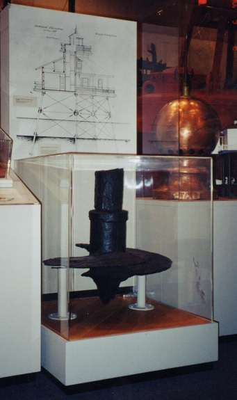
6 Mitchell Screw Pile 1835
7 A. B. Chance Historically an Anchor Company Since 1912
8 Centralia, MO

9 Centralia, MO

10 Never Creep Anchor

11 Copy of Original Never Creep Patent

12 Early Anchor Pull Test with Office Staff
13 CHANCE Civil Construction Products Atlas Resistance Piers CHANCE Helical Anchors CHANCE Helical Piles
14 APPLICATIONS Guy Anchors & Foundations for Towers Helical Piles for New Construction Underpinning - Residential / Commercial Tiebacks for Excavation Bracing Soil Screws for Earth Retention Slope Stabilization Seismic Retro-fit Tie-Downs

15 BUILDING CODE EVALUATION REPORTS ICC-ES Legacy Report B ICC-ES Legacy Report ICC-ES Legacy Report - ER5110 ICC-ES Acceptance Criteria for Helical Foundation Systems and Devices
16 What is a helical pier? A device used to attach or support a load at or near the surface of the earth. Consists of Three Parts: Termination: Transfers applied load to the shaft (Repair Brackets, Guy Adapters, Shackles, etc.) Shaft, or Rod: Transfers load to bearing element (Square Shaft or Round Pipe) Bearing Element: Transfers applied load to soil (Helix or Starter Section for Resistance Pier)
17 Square Shaft Helical Piers Lead Section Helical Extension Extension
18 Importance of Helix Shape Side View of True Helix Form Helix formed by matching metal die so that soil disturbance is minimized.
19 Standard Helix Diameters 6-inch 8-inch 10-inch 12-inch 14-inch 16-inch
20 CHANCE Shaft-Material Identification There are two rows of numbers and letters stamped on the shaft. Lead Section Example: (stamped under drilled hole) C403 N382 Extension Example: (stamped on one side) C403 (stamped at 90º to first side) N382 Lead Sections C403 N382 Material Year Steel Supplier Heat Number Extensions Material Code Product C4 TT64 SS5 C6 TT76 SS150, SS175 SS200, SS225

21 CHANCE is ISO 9001 Certified Anchor Type Date of Manufacture Steel Supplier Heat Run
22 CHANCE Helical Anchor Shafts Torsion & Tension Ratings SS125 4,000 ft-lb 60 kip SS1375 5,500 ft-lb 75 kip SS5 5,500 ft-lb 70 kip SS150 7,000 ft-lb 70 kip SS175 11,000 ft-lb 100 kip SS200 16,000 ft-lb 150 kip SS225 23,000 ft-lb 200 kip
23 Square Shaft Couplings
24 Square Shaft Tension Terminations
25 Round Shaft Sizes RS ,500 ft-lb 50 kip RS ,500 ft-lb 60 kip RS ,500 ft-lb 100 kip RS ,000 ft-lb 120 kip RS ,000 ft-lb 140 kip

26 Helical Pipe Shaft Couplings
27 SS to Pipe Shaft 1-1/2 SS to 2-7/8 Pipe 1-3/4 SS to HS (3.5 O.D. x Wall) 2 SS to HS 2-1/4 to 4.5 O.D (Atlas)

28 8 Pipe Shaft to 2 Square Shaft with 3 Helixes

29 21-8 Pipe Shaft 7 SS200 2 Sq. Shaft with

30 Large Diameter Pipe Piles


31 Large Diameter Pipe Piles Box Coupling Lead Section
32 Remedial Repair Bracket Terminations
33 Determining Capacity Helical Anchor/Foundation In soil Soil Borings/Calculations Torque Correlation Load Test
34 Bearing Capacity Equation Q h = A h (N c c + q N q ) <= Q s where: Q h = individual helix bearing capacity A h = projected helix area c = cohesion q = effective overburden pressure N q = bearing capacity factor Q s = limit determined by strength of helix
35 Plate Bearing Capacity Model Q ULT = Q H Shaft Friction = 0 H1 = 5D (minimum) Helix Spacing = 3D

36 Theoretical Bearing Capacity Based on Soil Strength Available from A. B. Chance Civil Construction Web Site -


37
38 INSTALLATION TORQUE CORRELATION TO CAPACITY
39 INSTALLATION TORQUE VS. ULTIMATE CAPACITY The Torque Required to Install a Helical Pile or Anchor is Empirically Related to Its Ultimate Capacity. Q ult = K t T Where: Qult = Ultimate Capacity [lb (kn)] K t = Empirical Torque Factor [ft-1 (m-1)] Default Value = 10 (33) for Type SS Default Value = 8 (26) for 2-7/8 Pipe Shaft Default Value = 7 (23) for 3-1/2 Pipe Shaft T = Installation Torque, [ft-lb (kn-m)]
40 RELIABILITY OF TORQUE/CAPACITY MODEL Uplift Capacity of Helical Anchors in Soil [Hoyt & Clemence 1989] Analyzed 91 Load Tests 24 Different Test Sites Sand, Silt, and Clay Soils Represented Calculated Capacity Ratio (Q act /Q calc ) Three Different Load Capacity Models Cylindrical Shear Individual Bearing Torque Correlation Torque Correlation Method Yields More Consistent Results than Soil Borings or Calculation Best Suited for On-Site Production Control and Termination Criteria
41 TORQUE INDICATORS Measuring Installation Torque Shaft Twist Visible Indication of Torque (Square Shaft) Shear Pin Torque Limiter Point-Wise Indicator Simple Design, Easy to Use Mechanical Dial Indicator Continuous Reading Indicator Never Needs Re-calibration Differential Pressure Indicator Continuous Reading Indicator No Moving Parts In-Line Hydraulic Pressure Gauge Simplest, Lowest Cost, Easy to Use Continuous Reading Indicator Least Accurate
42 Acceptable Shaft Twist

43 Unacceptable Shaft Twist


44 Torque Indicators Shear Pin Torque Limiter Dial Torque Indicator Differential Pressure Indicator
45 LOAD TESTING TO VERIFY CAPACITY
46 INSTALLATION TORQUE (FT-LB Mt. Pleasant, South Carolina Helical Pile Installation Torque vs. Depth 8, 10, 12 & 14 & Helix Configuration with 4.7" Average Dia. Grout Column INSTALLED DEPTH (FT)

47 Compression Load Test Set-Up Spreader Beam Load Beam Reaction Anchor Hydraulic Jack
48

49
50
51
52 DEFLECTION Sample Load-Deflection Curve of Compression Test LOAD + P ULT PL/AE + DESIGN LOAD = P ULT / times the Diameter MECHANICAL RATING OF SCREW PILE/ANCHOR
53 DISPLACEMENT (IN.) PILE LOAD TEST - TYPE SS200 SERIES PILE (Configuration: 6",8",10",12",14",14") QUIK-TRIP DISTRIBUTION FACILITY LOAD VS. DISPLACEMENT GRAPH - AVE. "A" & "B" DIAL INDICATOR READINGS Ave A & B Dial Indicator Rdgs ,000 20,000 30,000 40,000 50,000 60,000 70,000 80,000 90, , , , , , , , , , , ,000 APPLIED LOAD (LBS.)
54 Corrosion Consideration for Permanent Structures The data indicate that undisturbed soils are so deficient in oxygen at levels a few feet below ground line or below the water table zone, that steel pilings are not appreciably affected by corrosion, regardless of the soil types or the soil properties. - from National Bureau of Standards Monograph 127 by Romanoff Screw Anchor Components are Hot Dip Galvanized per ASTM A153 or A123. Galvanizing will add between 5% and 20% to the life of the anchor. Metal Loss Rates in Disturbed Soils Based on Field Tests Conducted by National Bureau of Standards. CHANCE Bulletin contains metal loss rate data. Nillson Resistivity Meters Available from Atlas Systems
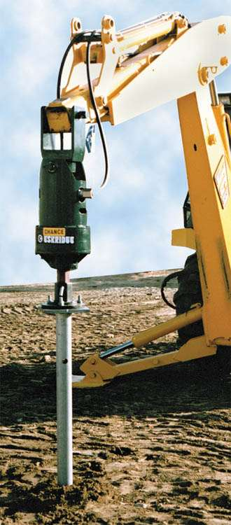


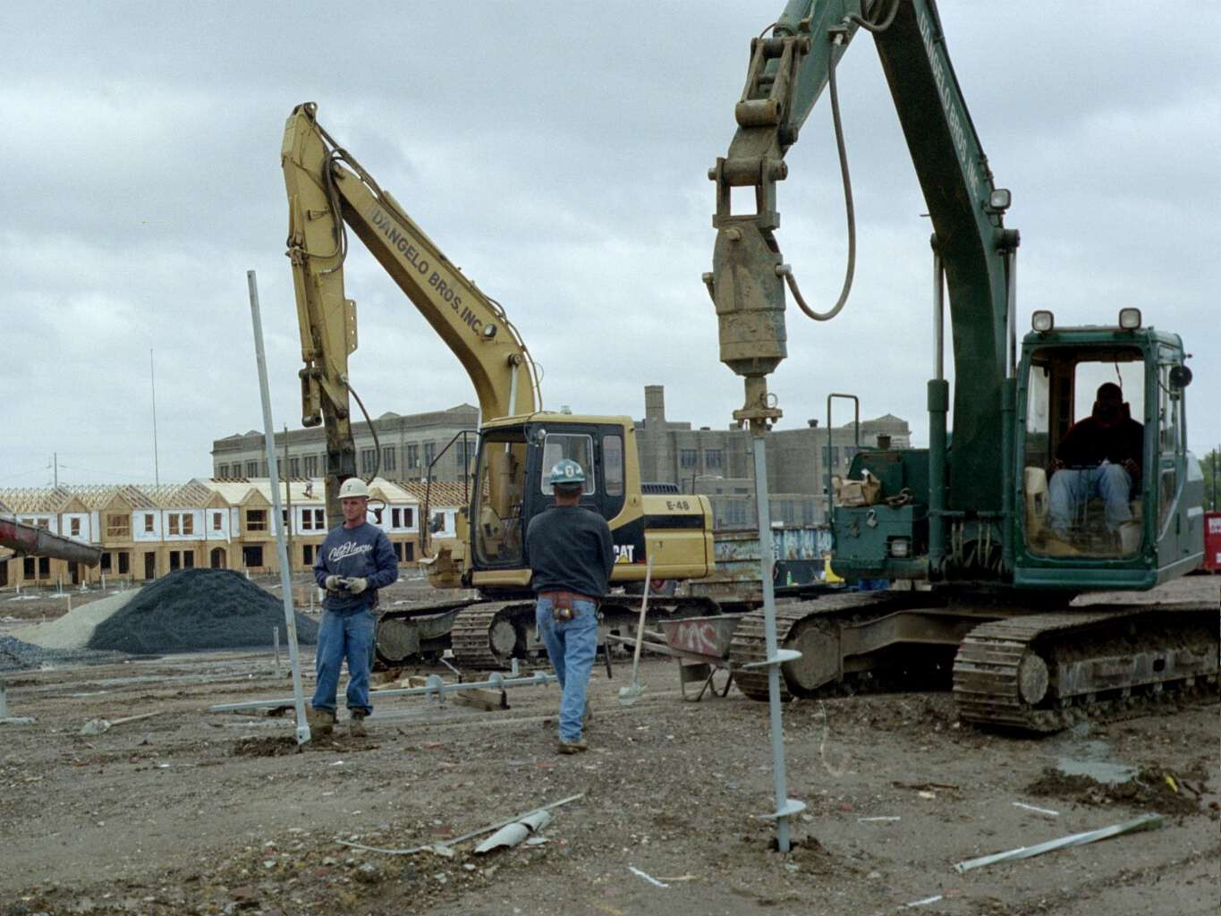
55 Installation Equipment Torque Motors 3,500 ft-lb 6,000 ft-lb 12,000 ft-lb 20,000 ft-lb

56 MACHINE CROWD TORQUE MOTOR TORQUE INDICATOR FOUR HELIX LEAD SECTION

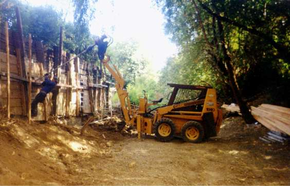

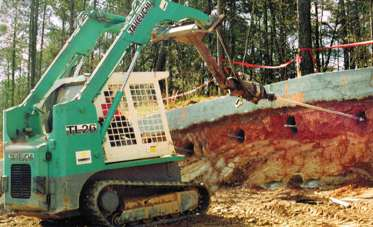
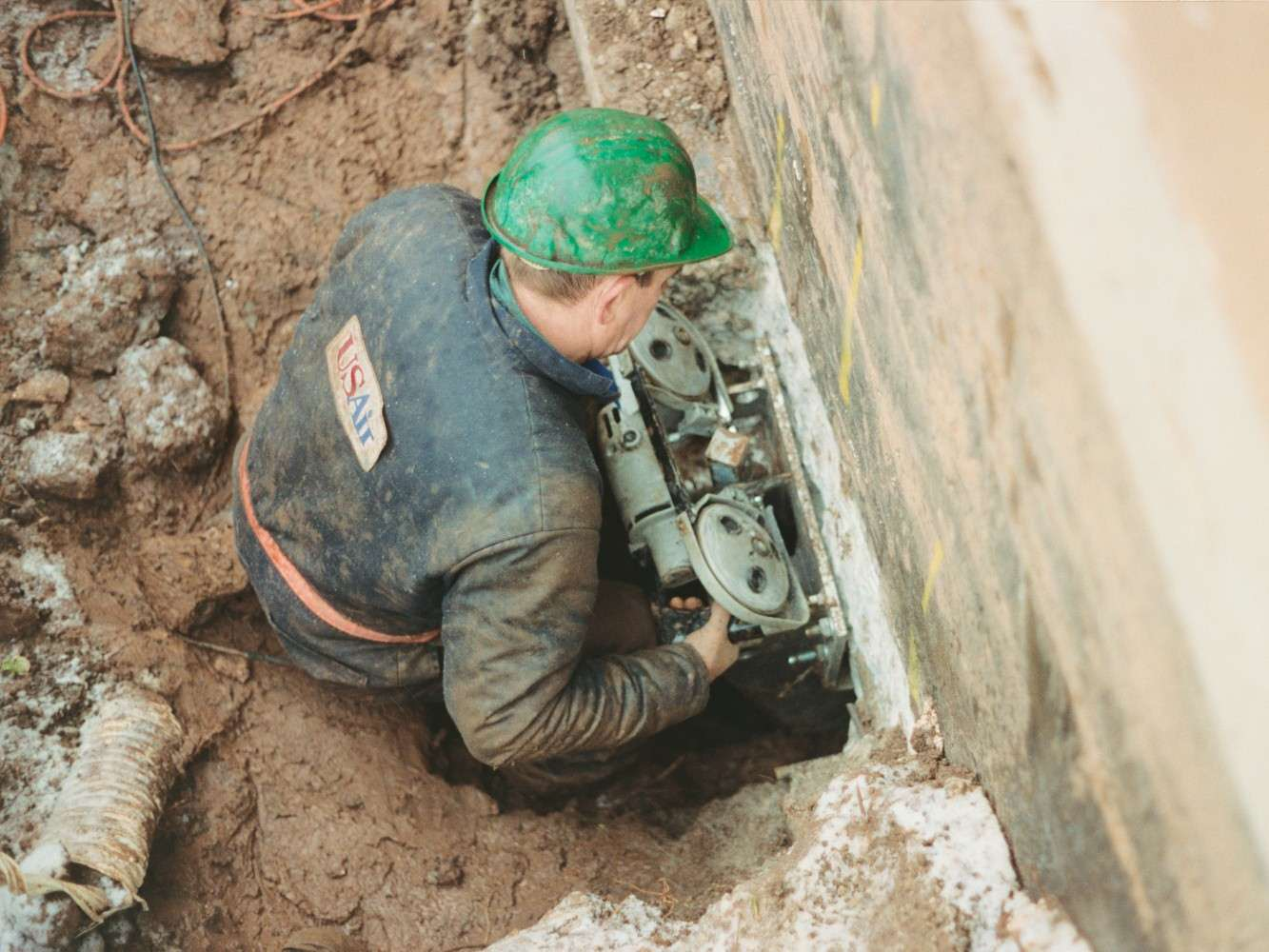
57 MACHINE INSTALLATION UP CLOSE


58 OR, FAR AWAY!
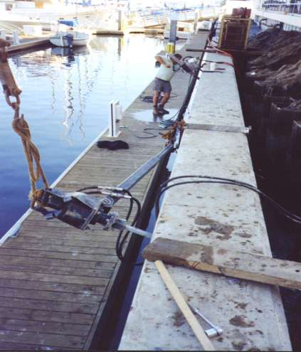
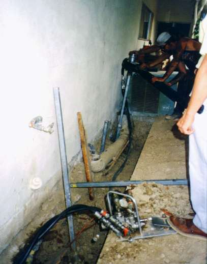
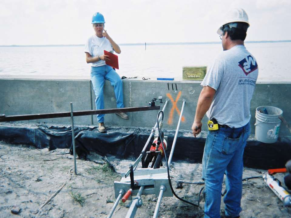
59 PORTABLE INSTLLATION FOR TIGHT ACCESS

60 Portable Installer Hydraulic Motor Torque Arm Foot Control
61 Applications
62 Tension Anchors
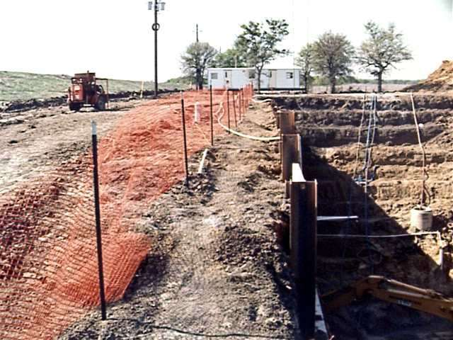
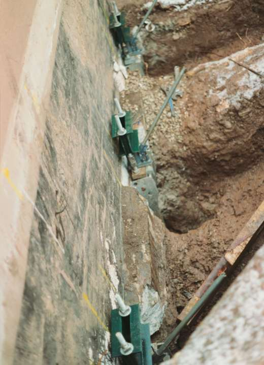
63 Helical Tiebacks

64 Screw Anchor Tiebacks
65

66
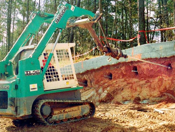
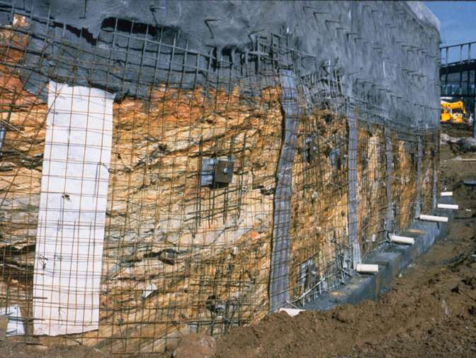
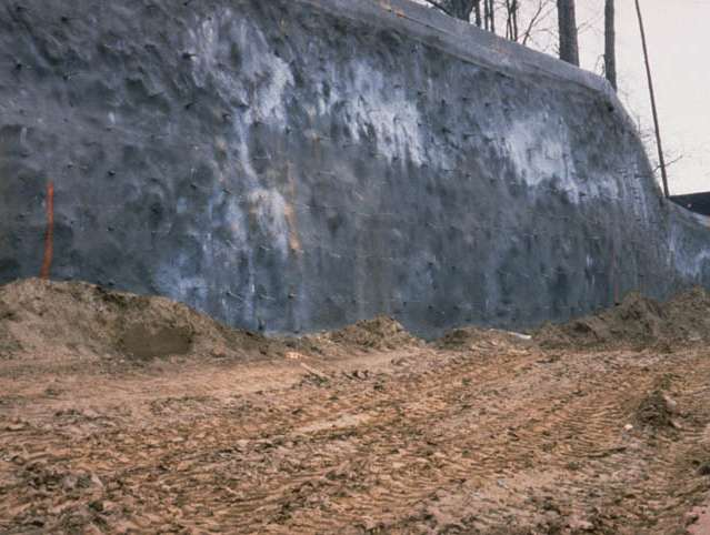
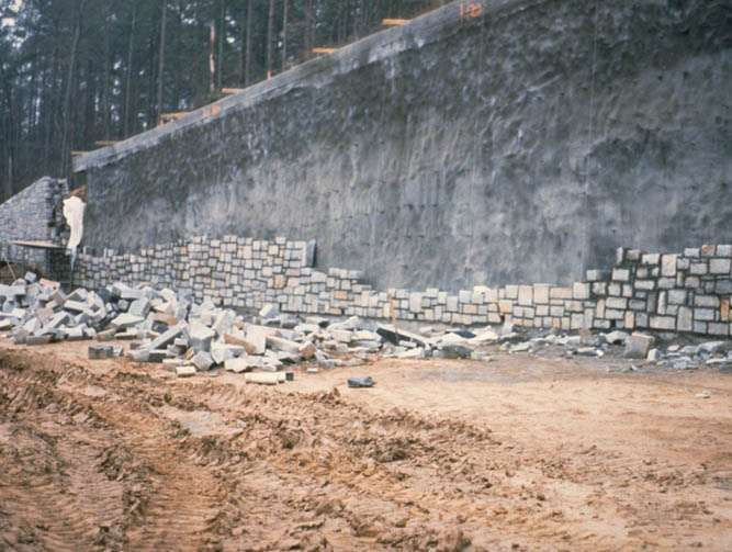
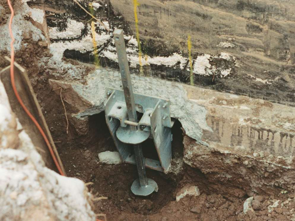
67 SOIL SCREW Retention Wall System
68 SOIL NAIL Installation Sequence

69 Soil Screw Retention Wall System
70
71
72
73

74 Guy Anchors for Telecomm Towers
75 Pipeline Buoyancy Control Synthetic Band System


76 Helical New Construction - Vertical and Diagonal for Hillside Application
77 Compression Anchors Residential/Commercial Underpinning New Construction Helical Pulldown Micro Piles Large Capacity Pipe Piles

78 Foundation Underpinning

79 HELICAL PIER Foundation Systems Remedial Repair

80

81
82
83

84

85
86

87


88 New Construction Bracket C for 1 ½ Square Shaft 40,000 lb design load C for 1 ¾ Square Shaft 60,000 lb design load


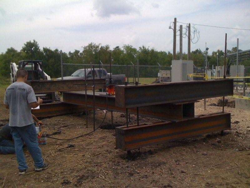
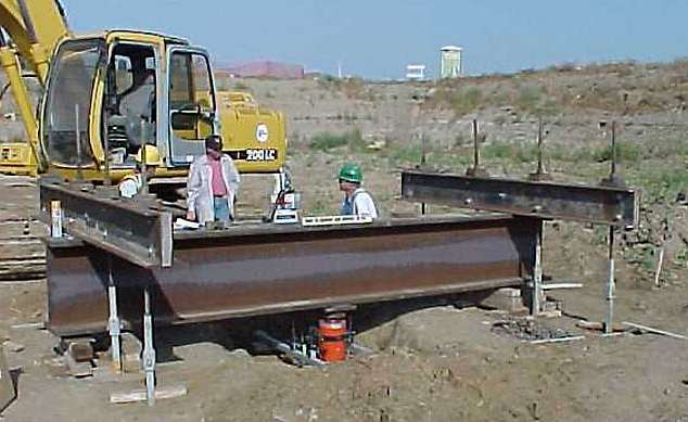
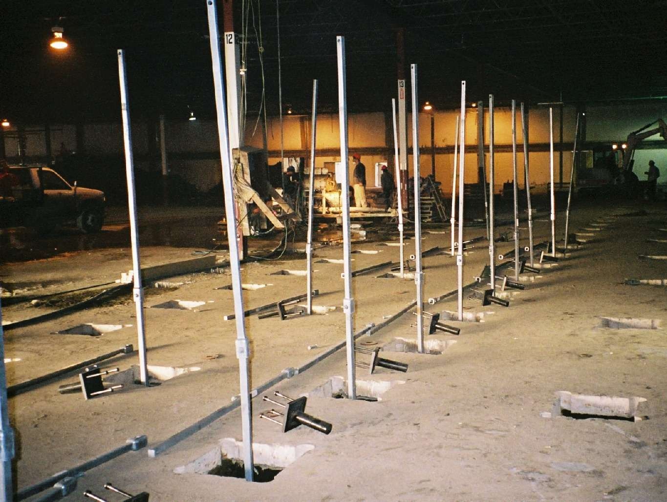
89 New Construction - Slabs and Foundations Access Limitations on Industrial Site Helical Piles Supporting Structural Slab
90
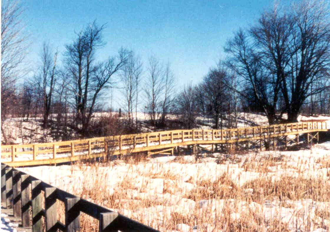
91 Boardwalk

92 Boardwalk

93

94 Walkways for Wetlands

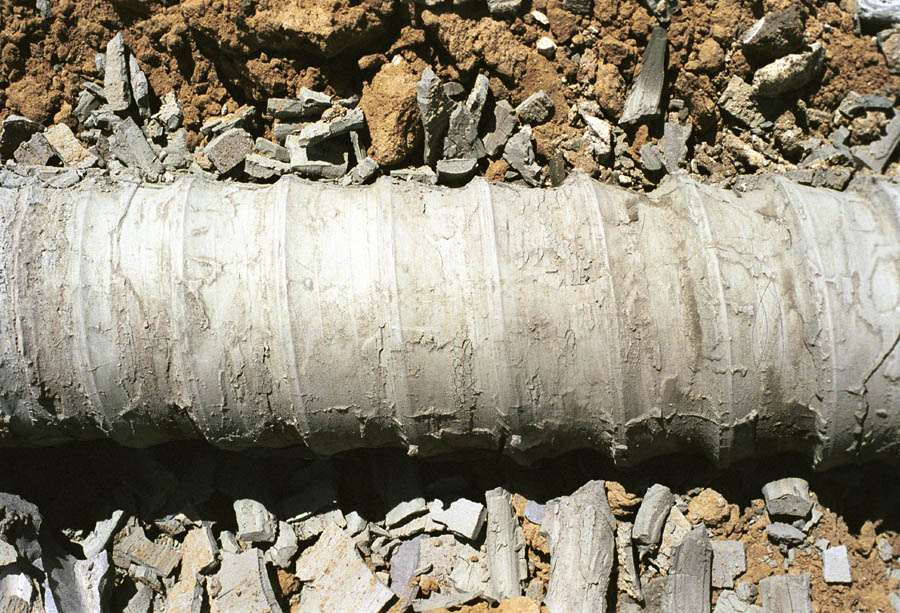
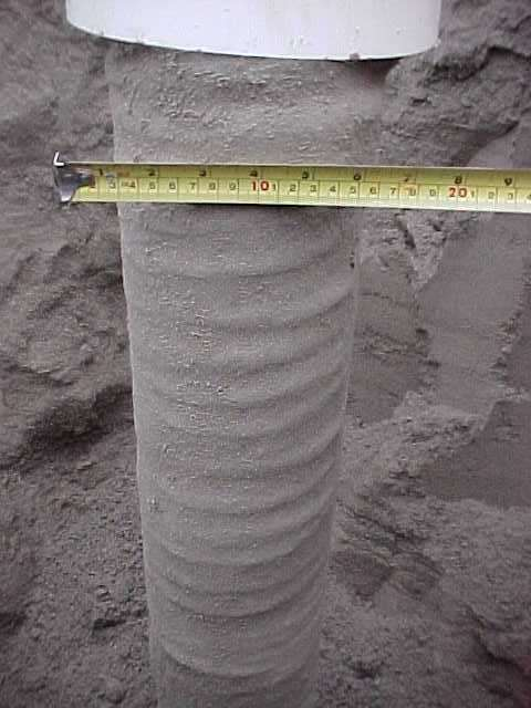
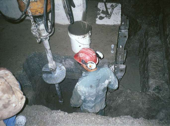
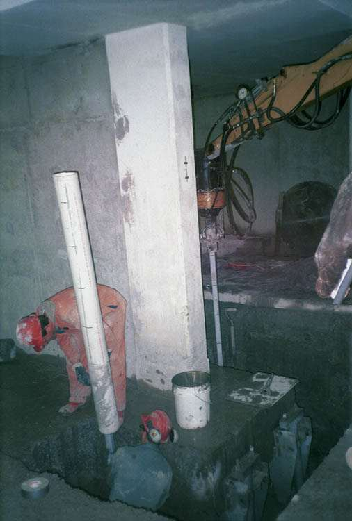
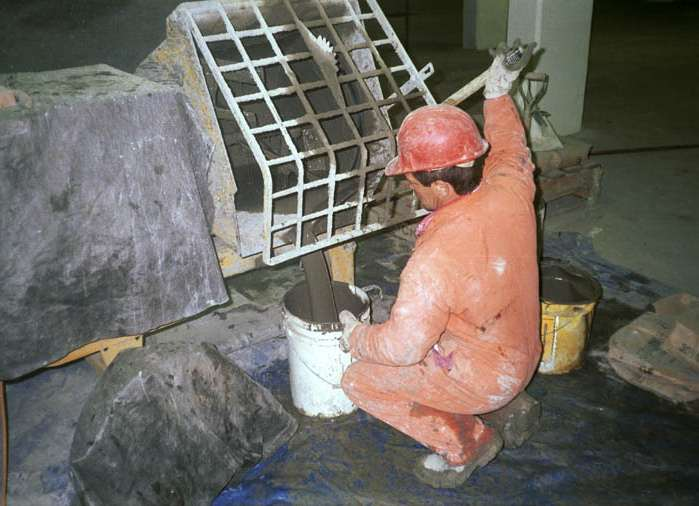
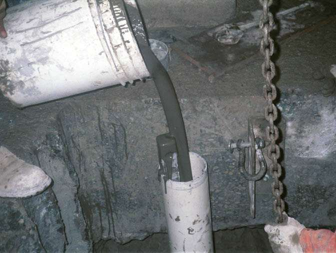
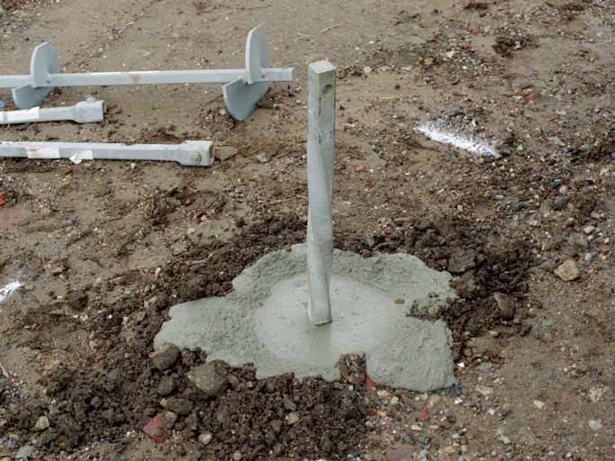
95 HELICAL PULLDOWN Micropile
96 Load-Settlement Curves Relative Development of Side and Base Resistance Maximum side resistance (friction) is mobilized after downward displacement of from 0.5 to greater than 3 percent of the shaft (grout column) diameter, with a mean of approximately 2 percent [Reese, Wright (1977)]. This side resistance or friction continues almost equal to the ultimate value during further settlement. No significant difference is found between cohesive and cohesionless soil except that further strain in clay sometimes results in a decrease in shaft resistance to a residual value. In contrast, the point (end bearing) resistance develops slowly with increasing load and does not reach a maximum until settlements have reached on the order of 10 percent of the diameter of the base (largest helix) [Terzaghi, Peck (1948)].
97 Design Advantages Buckling Resistance Soft/Loose soils overlying competent bearing strata Mobilization of Skin Friction Total capacity a function of skin friction and end bearing Additional Corrosion Protection Microsil grouts Optional casing Enhanced Load/Deflection Response Increases shaft stiffness Stiffens load/deflection response
98 TOTAL CAPACITY Q t = Q h + Q f where: Q t = Ultimate Static Resistance of the Screw Pile End-Bearing Pile Majority of Capacity Developed in End- Bearing Friction Pile Majority of Capacity Developed in Skin Friction Composite Pile Significant Capacity in Both End-Bearing and Skin Friction
99 GENERAL FRICTION CAPACITY EQUATION where: Q f = [πd f s ΔL f ] D = Diameter of Grouted Pile Column f s = Sum of Friction and Adhesion between Soil and Pile (force/area) ΔL f = Incremental pile length over which π D and f s are taken as constant
100
101

102

103

104
105
106
107
108

109

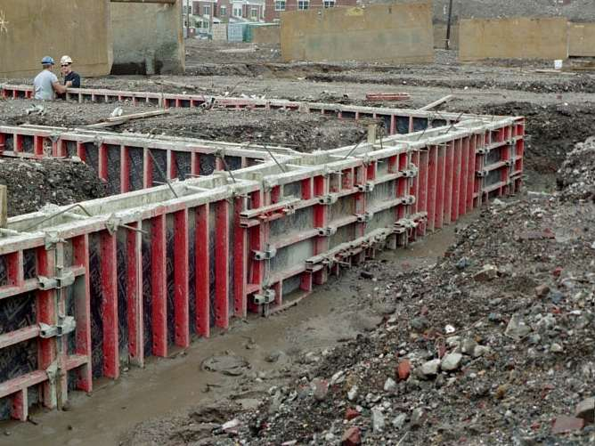
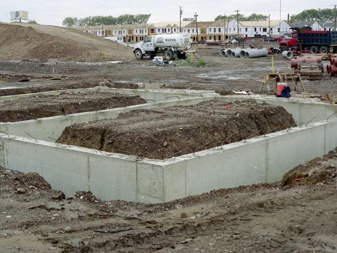
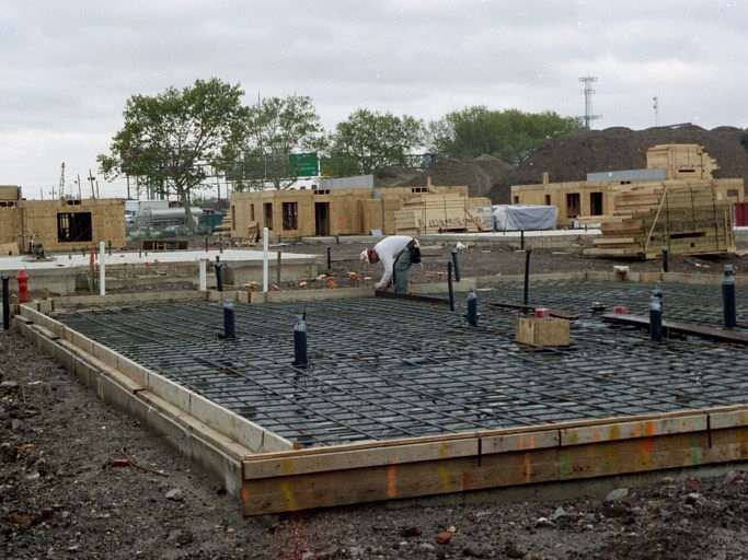
110 New Construction HPM Tasker Homes Philadelphia, PA
111 554 Residential Units 18 City Blocks 44 Acre Site

112 Grade Beam & Helical Pier Detail 3645 Helical Piers Installed Design Load: 40 Ton (80 Ton Ultimate) Preproduction Load Tests: 8 Depth: 15 to 60 feet Production: 20 to 60 Piers/Day/Machine Soil: Urban Fill underlain by Sand & Gravel
113 Typical Plan View Residential Dwelling Unit
114 Incorporate Tolerance for Installation Location ± 3 inches Within Tolerance (3631 Places or 99.6 %) ± 3 to 9 inches Out of Tolerance (14 Places or 0.4 %) > 9 inches Out of Tolerance (0 Places)
115
116

117

118

119
120
121
122

123 HELICAL PULLDOWN Micropile Structural Slab Upgrade
124
125
126
127
128
129

130

131
DESIGN, INSTALLATION AND TESTING OF HELICAL PILES & ANCHORS. Presented by: Donald A. Deardorff, P.E. CHANCE Civil Construction Centralia, MO USA
 DESIGN, INSTALLATION AND TESTING OF HELICAL PILES & ANCHORS Presented by: Donald A. Deardorff, P.E. CHANCE Civil Construction Centralia, MO USA Historical Perspective 1 st Recorded Screw Pile was by Alexander
Comprehensive Design Example 2: Foundations for Bulk Storage Facility
 Comprehensive Design Example 2: Foundations for Bulk Storage Facility Problem The project consists of building several dry product storage silos near an existing rail siding in an open field presently
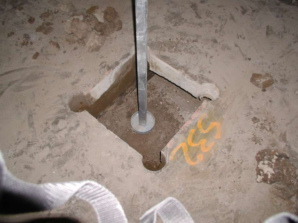
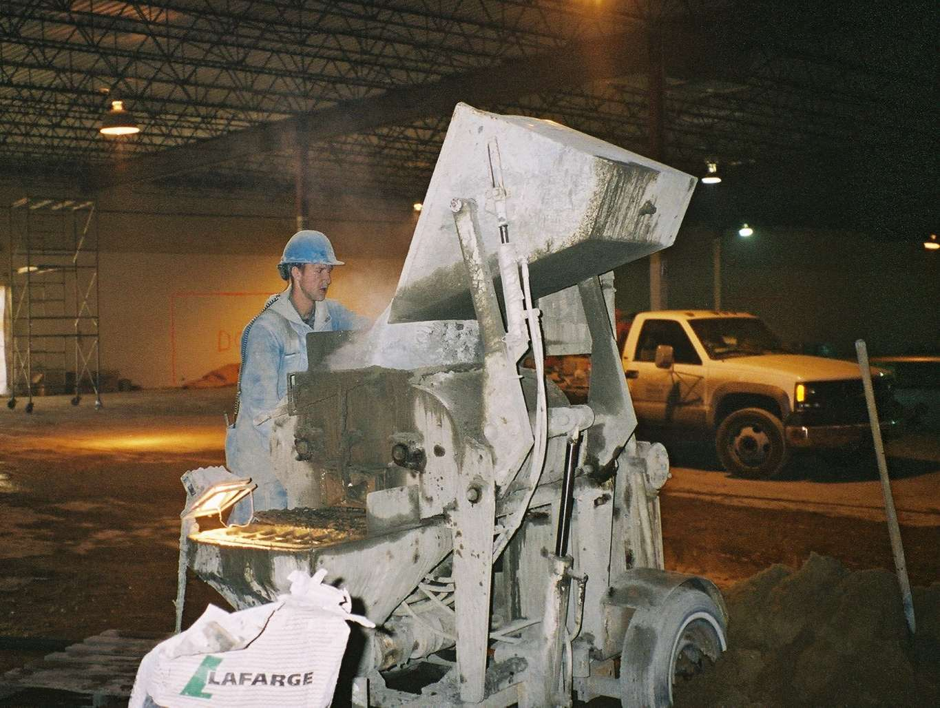
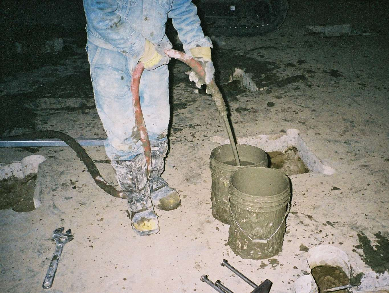
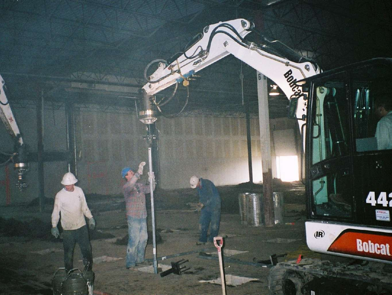
Figure A-1. Figure A-2. continued on next page... HPM-1. Grout Reservoir. Neat Cement Grout (Very Flowable) Extension Displacement Plate
 Extension Displacement Plate") Addendum HELICAL PULLDOWN Micropile (HPM) Introduction The HPM is a system for constructing a grout column around the shaft of a standard Helical Screw Foundation (see Figure A1). To begin the process,
Addendum HELICAL PULLDOWN Micropile (HPM) Introduction The HPM is a system for constructing a grout column around the shaft of a standard Helical Screw Foundation (see Figure A1). To begin the process,
New construction Repairing failed or old foundations Retrofit foundations Permanent battered piers Machinery/equipment foundations
 from New construction foundations don t have to be a headache. The CHANCE Helical Pier Foundation System gives you the performance of concrete without the drawbacks and liabilities of driven piles and
System. Stability. Security. Integrity. 150 Helical Anchor
 Model 150 HELICAL ANCHOR System PN #MBHAT Stability. Security. Integrity. 150 Helical Anchor System About Foundation Supportworks is a network of the most experienced and knowledgeable foundation repair
Step 11 Static Load Testing
 Step 11 Static Load Testing Test loading is the most definitive method of determining load capacity of a pile. Testing a pile to failure provides valuable information to the design engineer and is recommended
Stability. Security. Integrity.
 Stability. Security. Integrity. PN #MBHPT Foundation Supportworks provides quality helical pile systems for both new construction and retrofit applications. 288 Helical Pile System About Foundation Supportworks
Page B-1 Hubbell Power Systems, Inc. All Rights Reserved Copyright 2014 LOAD TESTS
 Page B-1 Hubbell Power Systems, Inc. All Rights Reserved Copyright 2014 Appendix B CONTENTS STATIC (TIEBACKS)... B-3 STATIC AXIAL (COMPRESSION/TENSION)... B-6 STATIC (LATERAL)... B-9 CAPACITY VERIFICATION
High Capacity Helical Piles Limited Access Projects
 High Capacity Helical Piles Limited Access Projects Tel 403 228-1767 Canada, USA, Russia Brendan ODonoghue 519 830-6113 Presentation Summary 1. Helical piles Background on large diameter shafts and helices
LEGACY REPORT ER-5110. www.icc-es.org. ICC Evaluation Service, Inc. Reissued November 1, 2003. Legacy report on the 1997 Uniform Building Code
 LEGACY REPORT Reissued November 1, 2003 ICC Evaluation Service, Inc. www.icc-es.org Business/Regional Office # 5360 Workman Mill Road, Whittier, California 90601 # (562) 699-0543 Regional Office # 900
How to Design Helical Piles per the 2009 International Building Code
 ABSTRACT How to Design Helical Piles per the 2009 International Building Code by Darin Willis, P.E. 1 Helical piles and anchors have been used in construction applications for more than 150 years. The
Helical Piles. A Practical Guide to Design and Installation
 Brochure More information from http://www.researchandmarkets.com/reports/2216946/ Helical Piles. A Practical Guide to Design and Installation Description: An unbiased, comprehensive review of helical pile
Engineered, Time-Tested Foundation Repairs for Settlement in Residential and Light Commercial Structures. The Leading Edge.
 TM TM Engineered, Time-Tested Foundation Repairs for Settlement in Residential and Light Commercial Structures. SM The Leading Edge. 10 One Major Causes of foundation settlement or more conditions may
ATLAS RESISTANCE Pier Foundation Systems
 ATLAS RESISTANCE Pier Foundation Systems Foundation Repair Systems for Civil Construction Applications: Residential, Commercial, Industrial Atlas Resistance Piers have been used to restore and/or stabilize
A Solid Foundation Solution for Homeowners. from. Our products are made with 90% Recycled Material Down. Right. Solid. GREEN.
 A Solid Foundation Solution for Homeowners from Our products are made with 90% Recycled Material Down. Right. Solid. GREEN. Stop the damaging effects of foundation settling... Sinking foundations, cracked
The Stabilizer TM. Benefits. www.griptite.com. Supplemental support system for sagging beams and floor joists within a crawl space
 The Stabilizer TM Supplemental support system for sagging beams and floor joists within a crawl space Pre-drilled holes in steel plate allow for connection to beam or floor joists. Benefits Levels and
Helical Pier Foundation System U.S. Patents 5,011,336; 5,120,163; 5,213,448
 Helical Pier Foundation System U.S. Patents 5,011,336; 5,120,163; 5,213,448 Technical Manual Contents Helical Pier Foundation System History Research and Development Advantages Theory of Foundation Anchor
USE OF MICROPILES IN TEXAS BRIDGES. by John G. Delphia, P.E. TxDOT Bridge Division Geotechnical Branch
 USE OF MICROPILES IN TEXAS BRIDGES by John G. Delphia, P.E. TxDOT Bridge Division Geotechnical Branch DEFINITION OF A MICROPILE A micropile is a small diameter (typically less than 12 in.), drilled and
METHOD OF STATEMENT FOR STATIC LOADING TEST
 Compression Test, METHOD OF STATEMENT FOR STATIC LOADING TEST Tension Test and Lateral Test According to the American Standards ASTM D1143 07, ASTM D3689 07, ASTM D3966 07 and Euro Codes EC7 Table of Contents
Now That s IDEAL. Now That s IDEAL. LISTEN. RESEARCH. DESIGN. DELIVER.
 The Leading Edge SM At IDEAL, we try not to complicate things. We discover needs and problems, then work out solutions. It takes real teamwork to accomplish truly great things. That s you and us, working
SECTION 1 GENERAL REQUIREMENTS
 Page 1 of 6 SECTION 1 GENERAL REQUIREMENTS 1. SCOPE OF WORK: The work to be performed under the provisions of these documents and the contract based thereon includes furnishing all labor, equipment, materials,
Step 6 Buckling/Slenderness Considerations
 Step 6 Buckling/Slenderness Considerations Introduction Buckling of slender foundation elements is a common concern among designers and structural engineers. The literature shows that several researchers
Designed and Engineered to Perform
 History EARTH CONTACT PRODUCTS, L.L.C., is a family owned company, based in Olathe, Kansas. This company was built upon Don May s U.S. Patented fourth-generation Steel Piering System that has led to the
Design, Testing and Automated Monitoring of ACIP Piles in Residual Soils
 Design, Testing and Automated Monitoring of ACIP Piles in Residual Soils Stephen W. Lacz 1, M. ASCE, P.E. and Richard C. Wells 2, F. ASCE, P.E. 1 Senior Professional, Trigon Kleinfelder, Inc., 313 Gallimore
World Leader in earth anchoring since 1907. for Residential and Commercial Construction and Repairs
 Bulletin 01-9901 Rev. 02/03 POWER SYSTEMS, INC. World Leader in earth anchoring since 1907 INSTANT FOUNDATION Systems for Residential and Commercial Construction and Repairs with the speed of steel for
EVALUATING INSTALLATION DISTURBANCE OF HELICAL ANCHORS IN CLAY FROM FIELD VANE TESTS
 EVALUATING INSTALLATION DISTURBANCE OF HELICAL ANCHORS IN CLAY FROM FIELD VANE TESTS Alan J. Lutenegger, John Erikson and Nicholas Williams, Department of Civil & Environmental Engineering, University
Outline MICROPILES SUBJECT TO LATERAL LOADING. Dr. Jesús Gómez, P.E.
 MICROPILES SUBJECT TO LATERAL LOADING Dr. Jesús Gómez, P.E. Micropile Design and Construction Seminar Las Vegas, NV April 3-4, 2008 Outline When are micropiles subject to lateral load? How do we analyze
SUPPLEMENTAL TECHNICAL SPECIFICATIONS BI-DIRECTIONAL STATIC LOAD TESTING OF DRILLED SHAFTS
 July 14, 2015 1.0 GENERAL BI-DIRECTIONAL STATIC LOAD TESTING OF DRILLED SHAFTS This work shall consist of furnishing all materials, equipment, labor, and incidentals necessary for conducting bi-directional
ALLOWABLE LOADS ON A SINGLE PILE
 C H A P T E R 5 ALLOWABLE LOADS ON A SINGLE PILE Section I. BASICS 5-1. Considerations. For safe, economical pile foundations in military construction, it is necessary to determine the allowable load capacity
Residential Deck Safety, Construction, and Repair
 Juneau Permit Center, 4 th Floor Marine View Center, (907)586-0770 This handout is designed to help you build your deck to comply with the 2006 International Residential Building code as modified by the
Micropiles Reduce Costs and Schedule for Merchant RR Bridge Rehabilitation
 Micropiles Reduce Costs and Schedule for Merchant RR Bridge Rehabilitation Jeff R. Hill, P.E. Hayward Baker Inc. 111 W. Port Plaza Drive Suite 600 St. Louis, MO 63146 314-542-3040 JRHill@HaywardBaker.com
High Strain Dynamic Load Testing of Drilled Shafts
 Supplemental Technical Specification for High Strain Dynamic Load Testing of Drilled Shafts SCDOT Designation: SC-M-712 (9/15) September 3, 2015 1.0 GENERAL This work shall consist of performing high-strain
PILE FOUNDATIONS FM 5-134
 C H A P T E R 6 PILE FOUNDATIONS Section I. GROUP BEHAVIOR 6-1. Group action. Piles are most effective when combined in groups or clusters. Combining piles in a group complicates analysis since the characteristics
ENGINEERED FOUNDATIONS. Department of Public Works Jeff Hill, PE
 ENGINEERED FOUNDATIONS Department of Public Works Jeff Hill, PE What is an engineered foundation. A Foundation Design Developed by a Trained Professional (Engineer) Types of Foundations (All of which can
HELICAL SCREW PILE FOUNDATIONS. Presented by: Laurence Boakes Azimuth Structural Engineering Ltd.
 HELICAL SCREW PILE FOUNDATIONS Presented by: Laurence Boakes Azimuth Structural Engineering Ltd. Historical Perspective 1 st Recorded use of a Screw Pile was by Alexander Mitchell in 1836 for Moorings
Designed and Engineered to Perform
 History EARTH CONTACT PRODUCTS, L.L.C., is a family owned company, based in Olathe, Kansas. This company was built upon Don May s U.S. Patented fourth-generation Steel Piering System that has led to the
RAM JACK INTRODUCTION
 RAM JACK INTRODUCTION PROVEN BUSINESS MODEL Billions of dollars in damages are caused by inferior soils each year. How much of this business are you profiting from? Our business systems have proven to
PRODUCT DRAWINGS AND RATINGS Section 7
 PRODUCT DRAWINGS AND RATINGS Section 7 CONTENTS ATLAS RESISTANCE PIERS 7-1 PIER PIPE SHAFTS 7-1 REMEDIAL REPAIR BRACKETS for ATLAS RESISTANCE PIERS 7-2 ACCESSORIES for ATLAS RESISTANCE PIERS 7-6 CHANCE
HELICAL SCREW PILES (HSP) CAPACITY FOR AXIAL CYCLIC LOADINGS IN COHESIVE SOILS
 CAPACITY FOR AXIAL CYCLIC LOADINGS IN COHESIVE SOILS") 4 th International Conference on Earthquake Geotechnical Engineering June 25-28, 27 Paper No. 1567 HELICAL SCREW PILES (HSP) CAPACITY FOR AXIAL CYCLIC LOADINGS IN COHESIVE SOILS M. Hesham EL NAGGAR 1,
4 th International Conference on Earthquake Geotechnical Engineering June 25-28, 27 Paper No. 1567 HELICAL SCREW PILES (HSP) CAPACITY FOR AXIAL CYCLIC LOADINGS IN COHESIVE SOILS M. Hesham EL NAGGAR 1,
Annual Kansas City Specialty Seminar 2014. Recent Advances in Design and Construction of Helical Foundations
 Annual Kansas City Specialty Seminar 2014 Recent Advances in Design and Construction of Helical Foundations Helical Foundations History, Applications and Recent Research Dr. Samuel P. Clemence Syracuse
Underpinning Systems 14.1 FOUNDATION REPAIR. Helical Piles
 Helical Piles Howard A. Perko Copyright 0 2009 by John Wiley & Sons, Inc. All rights reserved. C h a p t e r 14 Underpinning Systems There has been tremendous growth in the use of helical piles for underpinning
The International Workshop on Micropiles, 2007
 MICROPILE FOUNDATION REPAIR AND UNDERPINNING, ARTS AND SCIENCE MUSEUM, UNIVERSITY OF PUERTO RICO, MAYAGUEZ Presented at: International Society of Micropiles (ISM) The International Workshop on Micropiles,
DIVISION: 31 00 00 EARTHWORK SECTION: 31 63 00 BORED PILES REPORT HOLDER: HUBBELL POWER SYSTEMS, INC.
 0 ICC ES Report ICC ES (800) 4 6587 (56) 699 054 www.icc es.org 000 Most Widely Accepted and Trusted ESR 794 Reissued 05/05 This report is subject to renewal 05/06. DIVISION: 00 00 EARTHWORK SECTION: 6
Evaluation Report CCMC 13102-R Pieux Vissés Vistech / Postech Screw Piles
 Evaluation Report CCMC 13102-R Pieux Vissés Vistech / Postech Screw Piles 1. Opinion 1of 6 MASTERFORMAT: 31 62 16.01 Evaluation issued: 2003-02-13 Re-evaluated: 2015-03-13 Re-evaluation due: 2018-02-13
PTS HELICAL PIERS INSTALLATION SPECIFICATIONS NOTICE
 FORM A PTS HELICAL PIERS INSTALLATION SPECIFICATIONS NOTICE The following suggested specifications are written as a guide to assist the specifier in writing his own specifications. Specific circumstances
Atlantic Foundation & Repair
 Atlantic Foundation & Repair 12º 14º The Articulating Bracket is one of the reasons Atlantic Foundation & Repair's Stabilizor is the best foundation repair system made, the other reason is that it does
Foundation Underpinning Process and Relationship with Groundwater in West- Central Florida
 Foundation Underpinning Process and Relationship with Groundwater in West- Central Florida Ahmed Said, PhD, PE Principal Engineering Consultant, Sinkhole Geotech, Inc. e-mail: admin@sinkholegeotech.com
load on the soil. For this article s examples, load bearing values given by the following table will be assumed.
 How Many Piers? By Gary Collins, P.E. A clear-cut guide to helical pier spacing Introduction Helical pier spacing is not an exact science. How many does it take to support a structure adequately or repair
For a Coastal Site. A Pier-and-Beam Foundation. Our company specializes in oceanfront
 A Pier-and-Beam Foundation For a Coastal Site Where unstable soil and periodic tidal flooding are a concern, helical piers topped with a concrete stem wall rise to the challenge by Fred Ambrose Our company
Helical Foundation Systems
 Helical Foundation Systems The leading edge in helical foundations MacLean-Dixie The Leading Edge MacLean-Dixie s helical foundation systems offer the leading edge. If you re still considering concrete
Lymon C. Reese & Associates LCR&A Consulting Services Tests of Piles Under Axial Load
 Lymon C. Reese & Associates LCR&A Consulting Services Tests of Piles Under Axial Load Nature of Services The company has a long history of performance of tests of piles and pile groups under a variety
National Council of Examiners for Engineering and Surveying. Principles and Practice of Engineering Structural Examination
 Structural Effective Beginning with the April 2011 The structural engineering exam is a breadth and exam examination offered in two components on successive days. The 8-hour Vertical Forces (Gravity/Other)
STRUCTURES. 1.1. Excavation and backfill for structures should conform to the topic EXCAVATION AND BACKFILL.
 STRUCTURES 1. General. Critical structures may impact the integrity of a flood control project in several manners such as the excavation for construction of the structure, the type of foundation, backfill
GEORGE J. CAMBOURAKIS, P.E., C. ENG. PRESIDENT & CHIEF STRUCTURAL ENGINEER
 GEORGE J. CAMBOURAKIS, P.E., C. ENG. PRESIDENT & CHIEF STRUCTURAL ENGINEER Professional Experience: Pride and Passion in the Art of Structural Engineering since 1979. Professional Registration: Professional
BRIDGE RESTORATION AND LANDSLIDE CORRECTION USING STRUCTURAL PIER AND GRADE BEAM
 BRIDGE RESTORATION AND LANDSLIDE CORRECTION USING STRUCTURAL PIER AND GRADE BEAM Swaminathan Srinivasan, P.E., M.ASCE H.C. Nutting/Terracon David Tomley, P.E., M.ASCE KZF Design Delivering Success for
5/1/2013. Topics. The challenge is to better maintain native characteristics of soils during and after construction
 PIN Foundations Topics Applications Design and Construction Flow Control Credits www.pinfoundations.com Copyright 2008, Pin Foundations, Inc. Curtis Hinman WSU Extension Faculty, Watershed Ecologist chinman@wsu.edu
Transmission Foundations. helical piles and guy anchors for transmission structures. www.hubbellpowersystems.com
 Transmission Foundations helical piles and guy anchors for transmission structures www.hubbellpowersystems.com Grid locked on your transmission job? Instant Foundation helical piles go places concrete
SAMPLE GUIDE SPECIFICATIONS FOR OSTERBERG CELL LOAD TESTING OF DEEP FOUNDATIONS
 Page 1 of 9 SAMPLE GUIDE SPECIFICATIONS FOR OSTERBERG CELL LOAD TESTING OF DEEP FOUNDATIONS 1. GENERAL REQUIREMENTS 1. Description of Work: This work consists of furnishing all materials, equipment and
INTRODUCTION. Intro-1. Copyright 2003 Hubbell, Inc. Helical Screw Foundation System Design Manual for New Construction A.B.
 INTRODUCTION Definition: Helical Screw Foundation The helical screw foundation can be devised into a deep foundation system to support or resist any load or application. Installed by lightweight mobile
Standard Test Method for Mechanical Cone Penetration Tests of Soil 1
 Designation: D 3441 98 AMERICAN SOCIETY FOR TESTING AND MATERIALS 100 Barr Harbor Dr., West Conshohocken, PA 19428 Reprinted from the Annual Book of ASTM Standards. Copyright ASTM Standard Test Method
FOUNDATION DESIGN. Instructional Materials Complementing FEMA 451, Design Examples
 FOUNDATION DESIGN Proportioning elements for: Transfer of seismic forces Strength and stiffness Shallow and deep foundations Elastic and plastic analysis Foundation Design 14-1 Load Path and Transfer to
Method Statement for Static Load Testing (Compression) for Micropiles
 for Micropiles") Method Statement for Static Load Testing (Compression) for Micropiles 1. INTRODUCTION This vertical compression pile maintained load test is usually carried out to ensure the structural and geotechnical
Method Statement for Static Load Testing (Compression) for Micropiles 1. INTRODUCTION This vertical compression pile maintained load test is usually carried out to ensure the structural and geotechnical
BUTE Department of Construction Management and Technology
 BUTE Department of Construction Management and Technology 02.10.2012 Definition 1: Foundation: The structure, that transmits the load of the building to the soil Definition 2: Load bearing soil (strata):
ITEM #0702770 OSTERBERG CELL LOAD TESTING OF DRILLED SHAFT
 ITEM #0702770 OSTERBERG CELL LOAD TESTING OF DRILLED SHAFT Description: This work shall consist of furnishing all materials, equipment and labor necessary for conducting an Osterberg Cell (O-Cell) Load
INDIRECT METHODS SOUNDING OR PENETRATION TESTS. Dr. K. M. Kouzer, Associate Professor in Civil Engineering, GEC Kozhikode
 INDIRECT METHODS SOUNDING OR PENETRATION TESTS STANDARD PENETRATION TEST (SPT) Reference can be made to IS 2131 1981 for details on SPT. It is a field edtest to estimate e the penetration e resistance
product manual HS-4210 HS-4210_MAN_09.08 Digital Static Cone Penetrometer
 HS-4210_MAN_09.08 product manual HS-4210 Digital Static Cone Penetrometer Introduction This Manual covers the measurement of bearing capacity using the Humboldt Digital Static Cone Penetrometer (DSCP).
TYPES OF PIERS USED IN NORTH AND EAST TEXAS RESIDENTIAL FOUNDATION REPAIR
 TYPES OF PIERS USED IN NORTH AND EAST TEXAS RESIDENTIAL FOUNDATION REPAIR If you listen to the hype, it sounds like there must be 20 or 30 different types of piers out there. Company A says they have an
CEEN 162 - Geotechnical Engineering Laboratory Session 7 - Direct Shear and Unconfined Compression Tests
 PURPOSE: The parameters of the shear strength relationship provide a means of evaluating the load carrying capacity of soils, stability of slopes, and pile capacity. The direct shear test is one of the
Dynamic Load Testing of Helical Piles
 Dynamic Load Testing of Helical Piles ANNUAL KANSAS CITY SPECIALTY SEMINAR 2014 JANUARY 10, 2014 Jorge Beim JWB Consulting LLC Pile Dynamics, Inc. Main Topics Brief description of the Dynamic Load Test
Copyright by W. Tom Witherspoon. All Rights Reserved. Soil Stabilzation of Oklahoma, Inc
 Copyright by W. Tom Witherspoon All Rights Reserved LOAD CAPACITY TESTING AND ANALYSIS OF RESIDENTIAL UNDERPINNING SYSTEMS IN EXPANSIVE CLAY ENVIRONMENT by WILLIAM THOMAS WITHERSPOON Presented to the Faculty
Up-Down Construction Utilizing Steel Sheet Piles and Drilled Shaft Foundations
 Up-Down Construction Utilizing Steel Sheet Piles and Drilled Shaft Foundations Nathan A. Ingraffea, P.E., S.E. Associate, KPFF Consulting Engineers, Portland, Oregon, USA Abstract The use of steel sheet
Type of Force 1 Axial (tension / compression) Shear. 3 Bending 4 Torsion 5 Images 6 Symbol (+ -)
 Shear. 3 Bending 4 Torsion 5 Images 6 Symbol (+ -)") Cause: external force P Force vs. Stress Effect: internal stress f 05 Force vs. Stress Copyright G G Schierle, 2001-05 press Esc to end, for next, for previous slide 1 Type of Force 1 Axial (tension /
Cause: external force P Force vs. Stress Effect: internal stress f 05 Force vs. Stress Copyright G G Schierle, 2001-05 press Esc to end, for next, for previous slide 1 Type of Force 1 Axial (tension /
Chapter 3 Pre-Installation, Foundations and Piers
 Chapter 3 Pre-Installation, Foundations and Piers 3-1 Pre-Installation Establishes the minimum requirements for the siting, design, materials, access, and installation of manufactured dwellings, accessory
Transmission Foundations Case History : Helical piles Hydro One Networks Inc.
 Transmission Foundations Case History : Helical piles Hydro One Networks Inc. www.hubbellpowersystems.com Late in 2008, an aerial patrol discovered three 500kV towers with partially-collapsed foundations
Load Testing of Drilled Shaft Foundations in Limestone, Nashville, TN Dan Brown, P.E., Ph.D.
 Dan A. Brown and Associates Consulting Geotechnical Engineers 300 Woodland Rd. (423)942-8681 Sequatchie, TN 37374 fax:(423)942-8687 Load Testing of Drilled Shaft Foundations in Limestone, Nashville, TN
CITY OF LOS ANGELES CALIFORNIA
 BOARD OF BUILDING AND SAFETY COMMISSIONERS VAN AMBATIELOS PRESIDENT E. FELICIA BRANNON VICE PRESIDENT JOSELYN GEAGA-ROSENTHAL GEORGE HOVAGUIMIAN JAVIER NUNEZ CITY OF LOS ANGELES CALIFORNIA ERIC GARCETTI
PC-Concrete Injectable Concrete Anchoring and Repair System
 PC-Concrete Injectable Concrete Anchoring and Repair System DESCRIPTION: PC-Concrete is a two component (1:1 ratio), 100% solids, high modulus, structural epoxy paste. PC-Concrete is a solvent free, no
ANALYSIS FOR BEHAVIOR AND ULTIMATE STRENGTH OF CONCRETE CORBELS WITH HYBRID REINFORCEMENT
 International Journal of Civil Engineering and Technology (IJCIET) Volume 6, Issue 10, Oct 2015, pp. 25-35 Article ID: IJCIET_06_10_003 Available online at http://www.iaeme.com/ijciet/issues.asp?jtype=ijciet&vtype=6&itype=10
The demand for new roadway
 Designing strong walls on weak soils Civil engineers have options to remedy foundation soil problems and meet project cost and schedule requirements. By Fadi Faraj, P.E.; Michael H. Garrison, P.E.; and
GUIDE TO MODEL SPECIFICATION CHANCE Civil Construction
 GUIDE TO MODEL SPECIFICATION CHANCE Civil Construction HELICAL PILES F STRUCTURAL SUPPT TYPES OF SPECIFICATIONS The three types of specifications that are used for Helical Pile projects are: Open Specifications:
VERTICAL MICROPILE LATERAL LOADING. Andy Baxter, P.G.
 EFFICIENT DESIGN OF VERTICAL MICROPILE SYSTEMS TO LATERAL LOADING Dr. Jesús Gómez, P.E. PE Andy Baxter, P.G. Outline When are micropiles subject to lateral load? How do we analyze them? Shear Friction
Dead load (kentledge) A structure over the test pile. Ground anchorage either by tension piles or ground anchors. Bi-directional (Osterberg-cell)
 A structure over the test pile. Ground anchorage either by tension piles or ground anchors. Bi-directional (Osterberg-cell)") Introduction Fugro LOADTEST Overview STATIC LOAD TESTING O-cell Bi-directional testing State of the art Dr Melvin England Fugro LOADTEST Static load tests Previous/existing technology Developments O-cell
Introduction Fugro LOADTEST Overview STATIC LOAD TESTING O-cell Bi-directional testing State of the art Dr Melvin England Fugro LOADTEST Static load tests Previous/existing technology Developments O-cell
Module 1 : Site Exploration and Geotechnical Investigation. Lecture 4 : In-situ tests [ Section 4.1: Penetrometer Tests ] Objectives
![Module 1 : Site Exploration and Geotechnical Investigation. Lecture 4 : In-situ tests [ Section 4.1: Penetrometer Tests ] Objectives](/thumbs/26/8734290.jpg "Module 1 : Site Exploration and Geotechnical Investigation. Lecture 4 : In-situ tests [ Section 4.1: Penetrometer Tests ] Objectives") Lecture 4 : In-situ tests [ Section 4.1: Penetrometer Tests ] Objectives In this section you will learn the following Penetrometer Tests Standard penetration test Static cone penetration test Dynamic cone
Lecture 4 : In-situ tests [ Section 4.1: Penetrometer Tests ] Objectives In this section you will learn the following Penetrometer Tests Standard penetration test Static cone penetration test Dynamic cone
Helical Pier Foundations
 Screw piers are a cost-effective option for steep sites and expansive soils Helical Pier Foundations FOR PROBLEMSITES SITES Our company, HighCraft Builders in Fort Collins, Colo., specializes in room additions
vulcanhammer.net This document downloaded from
 This document downloaded from vulcanhammer.net since 1997, your source for engineering information for the deep foundation and marine construction industries, and the historical site for Vulcan Iron Works
Geotechnical Investigation Reports and Foundation Recommendations - Scope for Improvement - Examples
 Geotechnical Investigation Reports and Foundation Recommendations - Scope for Improvement - Examples Prof. V.S.Raju (Formerly: Director, IIT Delhi & Professor and Dean, IIT Madras) Email: rajuvs_b@yahoo.com
B.TECH. (AEROSPACE ENGINEERING) PROGRAMME (BTAE) Term-End Examination December, 2011 BAS-010 : MACHINE DESIGN
 PROGRAMME (BTAE) Term-End Examination December, 2011 BAS-010 : MACHINE DESIGN") No. of Printed Pages : 7 BAS-01.0 B.TECH. (AEROSPACE ENGINEERING) PROGRAMME (BTAE) CV CA CV C:) O Term-End Examination December, 2011 BAS-010 : MACHINE DESIGN Time : 3 hours Maximum Marks : 70 Note : (1)
No. of Printed Pages : 7 BAS-01.0 B.TECH. (AEROSPACE ENGINEERING) PROGRAMME (BTAE) CV CA CV C:) O Term-End Examination December, 2011 BAS-010 : MACHINE DESIGN Time : 3 hours Maximum Marks : 70 Note : (1)
EXAMPLE 1 DESIGN OF CANTILEVERED WALL, GRANULAR SOIL
 EXAMPLE DESIGN OF CANTILEVERED WALL, GRANULAR SOIL A sheet pile wall is required to support a 2 excavation. The soil is uniform as shown in the figure. To take into account the friction between the wall
Design and Construction of Auger Cast Piles
 Design and Construction of Auger Cast Piles 101 th Annual Road School 2015 3/11/2015 Malek Smadi, Ph.D., P.E. Principal Engineer - GEOTILL - Fishers, IN msmadi@geotill.com - www.geotill.com CONTENTS 1.
Design of Steel Structures Prof. S.R.Satish Kumar and Prof. A.R.Santha Kumar. The design of any foundation consists of following two parts.
 8.7. Design procedure for foundation The design of any foundation consists of following two parts. 8.7.1 Stability analysis Stability analysis aims at removing the possibility of failure of foundation
Acceptance Codes APPENDIX - A. Acceptance Criteria
 1111 Receipt of a satisfactory Test Report from WSDOT Materials Laboratory is required indicating the lot (or lots) or batch of material meets the requirement of the specifications under which it is listed.
Materials. Estimating Steel. Players. Materials. Shop Drawings. Detailing Process. Standard shapes. Fabricated members, Built-up sections
 Materials Standard shapes W sections, C channels, Structural T, Angles, Pipes, Tubes, Rods and Plates Fabricated members, Built-up sections Adding plates to beam flanges, Stiffeners to beam webs Built
How To Design A Foundation
 The Islamic university - Gaza Faculty of Engineering Civil Engineering Department CHAPTER (2) SITE INVESTIGATION Instructor : Dr. Jehad Hamad Definition The process of determining the layers of natural
STATIC PILE LOAD TEST MANUAL. GEOTECHNICAL CONTROL PROCEDURE GCP-18 Revision #4
 STATIC PILE LOAD TEST MANUAL GEOTECHNICAL CONTROL PROCEDURE GCP-18 Revision #4 AUGUST 2015 GEOTECHNICAL CONTROL PROCEDURE: STATIC PILE LOAD TEST MANUAL GCP-18 Revision #4 STATE OF NEW YORK DEPARTMENT
DESIGNING STRUCTURES IN EXPANSIVE CLAY
 DESIGNING STRUCTURES IN EXPANSIVE CLAY A GUIDE FOR A RCHITECTS AND E NGINEERS Table of Contents 1. Introduction Page 1 2. Common Foundation Systems Page 2 3. Drilled Piers Page 3 a. Skin Friction Piers
Helical Piles and Anchors Hydraulically Driven Push Piers Polyurethane Injection Supplemental Support Systems
 Helical Piles and Anchors Hydraulically Driven Push Piers Polyurethane Injection Supplemental Support Systems FSI Technical Manual Second Edition July 2014 NOTICE AND DISCLAIMER The information contained
Soil Screw Design Manual Edition 2
 Soil Screw Design Manual Edition 2 Page TOC-1 Hubbell Power Systems, Inc. All Rights Reserved Copyright 2015 CONTENTS CONTENTS TABLE of CONTENTS INTRODUCTION and APPLICATIONS Section 1 PURPOSE AND SCOPE...
Introduction to Solid Modeling Using SolidWorks 2012 SolidWorks Simulation Tutorial Page 1
 Introduction to Solid Modeling Using SolidWorks 2012 SolidWorks Simulation Tutorial Page 1 In this tutorial, we will use the SolidWorks Simulation finite element analysis (FEA) program to analyze the response
DYNAMIC TESTING OF MICROPILES. COMPARISON OF STATIC AND DYNAMIC TEST RESULTS
 DYNAMIC TESTING OF MICROPILES. COMPARISON OF STATIC AND DYNAMIC TEST RESULTS D. Carlos Oteo 1, D. José Luis Arcos 2, D. Rafael Gil 3, D. Carlos Fdez. Tadeo 4 ABSTRACT Micropiles are used for many applications,
MANUFACTURED HOUSING USED AS DWELLINGS
 MANUFACTURED HOUSING USED AS DWELLINGS SECTION AE101 SCOPE AE101.1 General. These provisions shall be applicable only to a manufactured home used as a single dwelling unit and shall apply to the following: