|
|
|
- Benedict Baldwin
- 8 years ago
- Views:
Transcription
1 EN USER S GUIDE

2
3

4
5

6

7 [MODE] TIME [MODE] ALTIMETER [MODE] BAROMETER [MODE] COMPASS [MODE] HEART RATE MONITOR [SELECT] [SELECT] [SELECT] [SELECT] [SELECT] [SELECT] DAILY ALARMS [SELECT] DUAL TIME [MODE] [SELECT] DIFFERENCE MEASUREMENT [SELECT] 24 HOUR MEMORY [MODE] [SELECT] DIFFERENCE MEASUREMENT [SELECT] 4 DAY MEMORY [MODE] [SELECT] DECLINATION ADJUSTMENT [SELECT] COMPASS CALIBRATION [MODE] [SELECT] STOPWATCH [SELECT] INTERVAL TIMER [MODE] [SELECT] [SELECT] [SELECT] LOGBOOK SEA LEVEL PRESSURE MEMORY [SELECT] LOGBOOK HISTORY
![[SELECT] DIFFERENCE MEASUREMENT [SELECT] 4 DAY MEMORY [MODE] [SELECT] DECLINATION ADJUSTMENT [SELECT] COMPASS CALIBRATION](/docs-images/58/4485323/images/page_7.jpg "[MODE] [SELECT] STOPWATCH [SELECT] INTERVAL TIMER [MODE] [SELECT] [SELECT] [SELECT] LOGBOOK SEA LEVEL PRESSURE MEMORY [SELECT]")
8 USER S GUIDE EN CUSTOMER SERVICE CONTACTS Suunto Oy Phone Fax Suunto USA Phone 1 (800) Canada Phone 1 (800) European Call Center Phone Suunto Website

9 Table of Contents CHAPTER 1 Introduction General Information Main Functions (MODES) Water Resistance Backlight Features Button Functions The [Mode] Button The [+] Button The [-] Button The [Select] Button LCD Display Measurements and Units Selecting the Units of Measurement Pressure Sensor Calibration battery RePlaCeMenT of THe WRIsToP CoMPuTeR battery RePlaCeMenT of THe suunto TRansMITTeR belt...12 CHAPTER 2 Heart Rate Monitor Suunto Wristop Computer and transmitter in a water environment Suunto Wristop Computer and interference activating THe HeaRT RaTe MonIToR WaRnIngs Operation How to Set the Target Zones of the Heart Rate Monitor...16

10 2.6 Stopwatch Sub Mode How to Use the Stopwatch Interval Countdown Timer Sub Mode How to Set the Countdown Timer How to Start the Countdown Timer HRM Memory...21 CHAPTER 3 Time Mode How to Set the Time Daily Alarm Sub Mode How to Set the Daily Alarms Dual time Sub Mode Setting the Dual Time Function...26 CHAPTER 4 Altimeter Mode Setting the Altimeter Altitude difference Measurement Sub Mode How to Start the Altitude Difference Measurement hour Memory Sub Mode Logbook Sub Mode Closer examination of the logbook How to Start and Stop a Logbook Logbook History Sub Mode Clearing the Logbook History...35 CHAPTER 5 Barometer Mode Pressure Difference Measurement Sub Mode How to Start the Pressure Difference Measurement

11 5.2 4-Day memory Sub Mode Sea Level Pressure Sub Mode Setting the Sea Level Pressure Barometric Trend Indicator...39 CHAPTER 6 Compass Mode Bearing Tracking Sub Mode Declination Adjustment Sub Mode Setting the Local Declination Calibrating the Compass...42 CHAPTER 7 Frequently Asked Questions General Is the Wristop Computer waterproof? How long will the battery last? What do the segments on the circumference mean? Why do the segments on the circumference go to the left (counterclockwise)? Why are there two symbols above the mode texts and what do they mean? Heart Rate Monitor What should I do if there is no heart rate reading? What is the longest time I can set in the timer? Time Why do the segments on the circumference increase and decrease when I am in the Watch mode? Altimeter How do you clear the logbook? How does the logbook self-erase? How many logbooks can you record? What is the duration readout?

12 7.4.5 What is the maximum capacity of total vertical ascent or descent feet/meters in the logbook history? If hiking from a level of 5,000 ft down hill to 3,000 ft and then back up to 8,000 feet, how is the Wristop Computer going to read this or average it out? Why does the vertical ascent/descent measurement show different readings even though I am inside and staying in the same room? Barometer What is the little box on the top left of the display? Does the Wristop Computer show future trends in weather conditions? What does absolute pressure and relative pressure mean? What is temperature compensation? Compass What is the purpose of the rotating outer bezel? Where do I find the correct declination for my area so I can set my Wristop Computer? Effect of air temperature on altitude measurement SPARE PARTS AVAILABLE ABBREVIATIONS Copyright and Trademark Notice CE Compliance Limits of Liability and ISO 9001 Compliance Disposal of the Device

13 CHAPTER 1 Introduction 1.1 General Information The Wristop Computer is a reliable high precision electronic instrument, intended for recreational use. The outdoor enthusiast who enjoys venturing out into sports like skiing, kayaking, mountain climbing, hiking and biking can rely on the Vector HR s accuracy. The ergonomically designed Vector HR Wristop Computer weighs only 2 ounces (55 g) and features a large number style LCD display intended to be clearly visible in almost any condition. Note: The Wristop Computer is not intended to be used as a substitute for professional or industrial precision measurements and should never be used to acquire measurements when skydiving, hang gliding, paragliding, gyrocopter riding and flying small aircraft. Important Note: A pullout page IS located on the front cover. The page graphically illustrates and identifies the properties of the Wristop Computer and LCD display. It will facilitate the user s understanding of the functions and processes necessary to setup those functions. 1.2 MAIN FUNCTIONS (MODES) The Wristop Computer features five main functions: time, altimeter, barometer, compass, and heart rate monitor. Each function provides several sub modes further enhancing the usefulness to its owner. All main functions (modes) and sub modes are discussed in detail following this section. Note: The Heart Rate Monitor is the premier feature of the Wristop Computer. Details regarding this function are shown in Chapter 2 of this guide Water Resistance The Wristop Computer is waterproof to a depth of 30m/100ft. Note: The Wristop Computer is not a dive instrument, therefore buttons should not be operated (put to use) while under water Backlight Features The Wristop Computer has an electroluminescent backlight. This is initiated by pressing and holding the [Mode] button for 2 seconds. The backlight will remain on for 5 seconds. Pressing any button during this time will restart the 5 second period, continuing the backlight feature. 6

14 1.3 Button Functions Four buttons are used to operate the Wristop Computer: [Mode], [+] (ON/OFF), [-] (Fast Cumulative), and [Select] The [Mode] Button Is located on the top right of the Wristop Computer. In the main mode level, pressing the [Mode] button allows the user to select or move from one main mode or function to the next (TIME, ALTI, BARO, COMP, HRM). In the sub mode level, pressing the [Mode] button returns the user to the main mode level. In the setup process, pressing the [Mode] button accepts the changes or preferences. Pressing the button again will return the user to the main mode level. Pressing the button for 2 seconds activates the backlight feature The [+] Button Is located on the bottom right of the Wristop Computer. In the setup process, pressing the [+] button changes or scrolls the value upward. In the timing and recording functions, this button acts as a start/stop (On/Off) button. In the memory and logbook functions, this button advances through previous recorded screens The [-] Button Is located on the bottom left of the Wristop Computer. In the setup process, pressing the [-] button changes or scrolls the value downward. Also known as the Fast Cumulative button, by pressing the [-] button in any of the main modes, except the compass mode, the Wristop Computer will quickly access information about total vertical ascent/descent, number of runs completed as well as maximum, minimum and average heart rate of the current or last completed recording. In the compass mode, the [-] button locks the current bearing for 10 seconds. In the timing functions, this button acts as a reset or pause button. In the memory and logbook functions, this button backtracks through previously recorded screens. 7
![In the sub mode level, pressing the [Mode] button returns the user to the main mode level. In the setup process, pressing the [Mode] button accepts the changes or preferences.](/docs-images/58/4485323/images/page_14.jpg "Pressing the button again will return the user to the main mode level. Pressing the button for 2 seconds activates the backlight feature. 1.3.")
15 1.3.4 The [Select] Button Is located on the top left of the Wristop Computer. In the main mode level, pressing the [Select] button allows the user to enter into the sub modes of the particular function or return to the main mode the user is in. In the main mode or sub mode, pressing and holding the [Select] button for more than 2 seconds allows the user to enter the setup process. In the setup process, the [Select] button allows the user to move between settable units or values and determine preferences. 1.4 LCD Display The display is designed to offer maximum clarity and simplicity and is divided into six distinct viewable areas. The Outer Circumference encompasses the outer boundary of the LCD display. A Barometric Trend Indicator provides a quick reference for analyzing and collating possible conditions in the weather. Field 1 displays values in either numbers or text depending on the mode or sub mode the user is in. Field 2 displays large numbers and/or related unit of measure within the function. The Mode Indicator bar displays the five main modes (functions) of the Wristop Computer (a triangle arrow is just below indicating the mode). The fifth main mode, HR is displayed on the Outer circumference on the bottom right. When the one segment under HR is lit, the mode is activated for viewing and selection purposes. Field 3 displays either numbers and/or text. 8
![In the main mode or sub mode, pressing and holding the [Select] button for more than 2 seconds allows the user to enter the setup process.](/docs-images/58/4485323/images/page_15.jpg "In the setup process, the [Select] button allows the user to move between settable units or values and determine preferences. 1.")
16 1.5 Measurements and Units The Wristop Computer supplies two units of measure: metric or imperial. Metric Unit of Measure m m/min o C mbar Imperial Unit of Measure ft ft/min o F InHg 9

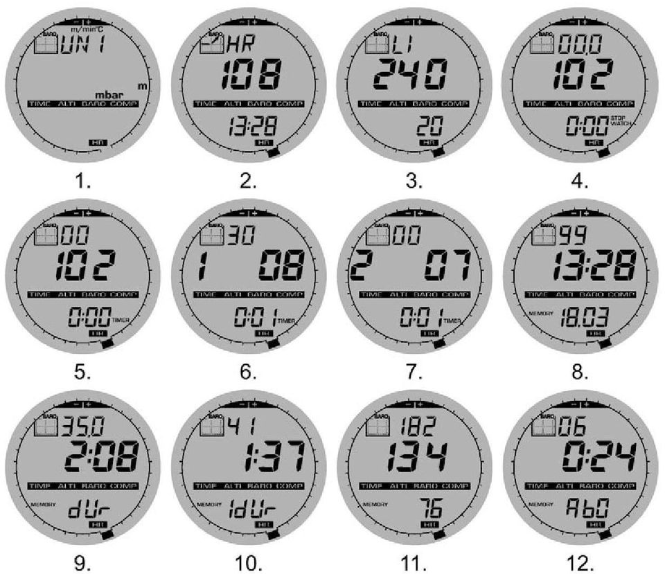
17 1.5.1 Selecting the Units of Measurement To change the units of measure displayed: 1. Check the mode indicator. If the mode arrow is not on TIME, PRESS the [Mode] button until the arrow is directly below TIME. 2. PRESS the [Mode] and [Select] buttons simultaneously and hold for 3 seconds. Field 1 will display SET momentarily and then display UNI (Fig. 1). Warning: If the user presses the [Select] button (and does not hold in for 3 seconds) while in the UNI setting mode, the user will be in the Pressure Sensor Calibration. Refer to the next sub-section for details. 3. PRESS the [Select] button and hold in for 2 seconds. Located to the right in Field 2, m or ft will begin to flash. 4. PRESS the [+] button to toggle between m and ft. 5. At the unit of measure desired, PRESS the [Select] button to move to the next unit. Located below the m or ft in Field 2, mbar or inhg will begin to flash. 6. PRESS the [+] button to toggle between mbar and inhg. 7. At the unit of measure desired, PRESS the [Select] button to move to the next unit. Located at the top right in Field 1 (just above the bubble), O C or O F will begin to flash. 8. PRESS the [+] button to toggle between C and F. 9. At the unit of measure desired, PRESS the [Select] button to move to the next unit. Located at the top center in Field 1, m/min or ft/min will begin to flash. 10. PRESS the [+] button to toggle between m/min and ft/min. 11. At the unit of measure desired, PRESS the [Mode] button to accept the changes. PRESS the [Mode] button again to return to the main time mode. Selecting the units of measurement is complete. Note: If the user does not press any button for 1 minute in the setup mode, the display will automatically exit setup. 10
 while in the UNI setting mode, the user will be in the Pressure Sensor Calibration.")
18 1.6 Pressure Sensor Calibration WARNING: This is a FACTORY CALIBRATION SETTING. Do not enter this mode. If you enter this mode in error, exit immediately by pressing the [MODE] button to return to the UNI setting mode. Normally there is no need to alter the calibration. If the Pressure Setting Calibration has been altered, you can return the factory setting. Proceed as follows: In the calibration setting mode, scroll the barometric pressure value up or down until text def appears. This is the factory setting. Then exit by pressing [MODE]. 1.7 Battery Replacement of the Wristop Computer The Wristop Computer operates on a three-volt lithium cell Type: CR The maximum life expectancy is approximately months. A low battery warning indicator is activated when 5-15 percent of the battery capacity is still available. When this occurs we recommend replacement of the battery. Extreme cold weather may activate the low battery-warning indicator. Though the indicator is activated, the battery may not need to be replaced due to this condition. In temperatures above 10 O C (50 O F) if the low battery warning indicator is activated, the battery will need to be replaced. Note: Heavy use of the electroluminescent backlight, the heart rate function, altimeter, and compass will significantly reduce the life of the battery. To replace the battery: 1. flip over the Wristop Computer to view the backside; 2. insert a coin in the coin slot located on the battery compartment cover; 3. turn the coin counterclockwise to the open position marked on the back of the case; 4. remove the battery compartment cover; 5. remove the old cell from the battery compartment and ensure the O-ring and all surfaces are clean, dry and not damaged. Do not stretch the O-ring. 11

19 6. place the new cell into the battery compartment (negative side down, positive side up); 7. ensure that the O-ring is in place to keep the Wristop Computer waterproof and place the battery compartment cover back onto the backside of the Wristop Computer; 8. insert a coin back into the coin slot; and 9. turn the coin clockwise to the close position marked on the back of the case. Note: Battery replacement should be performed with extreme care so as to ensure the Wristop Computer continues to remain waterproof. It is the operator s responsibility to take due care to ensure that the Wristop Computer remains waterproof. Note: After every battery replacement, it is necessary to calibrate the magnetic sensor. Details on performing this process are found in Calibrating the Compass section of this guide. 1.8 Battery Replacement of the Suunto Transmitter Belt The transmitter belt operates on a 3-Volt lithium cell, type: CR The average expected battery life of the transmitter belt is 200 hours of use in ideal operating temperatures. Replace the battery as illustrated here: Note: Suunto recommends that the battery cover and the O ring are changed simultaneously with the battery to ensure that the transmitter remains clean and water resistant. Replacement covers are available with replacement batteries. 12

20 CHAPTER 2 Heart Rate Monitor 2.1 SUUNTO Wristop Computer AND TRANSMITTER IN A WATER ENVIRONMENT Suunto Wristop Computer is water proof to a depth of 30m/100ft. To maintain the water resistance, it is strongly recommended to have all service done by authorised Suunto service personnel. Heart rate measurement in a water environment is technically demanding for the following reasons: Pool water with a high chlorine content and seawater may be very conductive and the electrodes of the transmitter may get short circuited and ECG (ECG = electrocardiogram) signals cannot be detected by the transmitter unit. Jumping into the water or strenuous muscle movement during competitive swimming may cause water resistance that shifts the transmitter on the body to a location where it is not possible to pick up the ECG signal. The ECG signal strength varies depending on the individual s tissue composition and the percentage of people who have problems with heart rate measurement is considerably higher in a water environment than in other use. Note: The Wristop Computer is not a dive instrument, and therefore buttons should not be operated (put to use) while under water. 2.2 SUUNTO Wristop Computer AND INTERFERENCE ELECTROMAGNETIC INTERFERENCE Disturbances may occur near high voltage power lines, traffic lights, overhead lines of electric railways, electric bus lines or trams, televisions, car motors, bike computers, some motor driven exercise equipment, cellular phones or when you walk through electric security gates. Electromagnetic interference may cause inaccuracy in receiving heart rate signals. The sum of the above, below and in heart rate values may be shorter than the total elapsed time. The reason for this inaccuracy is that the electromagnetic interference may prevent the Wristop Computer from receiving signals of the transmitter belt perfectly. 13
 signals cannot be detected by the transmitter unit.")
21 2.3 Activating the Heart Rate Monitor 1. Adjust the strap length to fit snugly and comfortably. Secure the strap around your chest, below the chest muscles. Lock the buckle. 2. Raise the transmitter a little off your chest and wet the grooved electrode areas on the back of it. It is important that the electrodes are wet during exercise. 3. Check that the wet electrode areas are firmly against your skin and the logo is in a central upright position. 4. Wear the wristop computer as you would wear an ordinary watch. Note: It is recommended that you wear the transmitter against your bare skin to ensure flawless operation. However, if you wish to wear the transmitter over a shirt, moisten the shirt well under the electrodes. When the Wristop Computer is in the Altimeter main mode, HRM main mode or any of the HRM sub modes and the transmitter is worn, the Wristop Computer will automatically search for a heart rate signal. This procedure also initiates the heart rate measurement. During the first minute, measurements are taken every second, then for the next 4 minutes every 5 seconds. If no heart rate signal has been received during the first five minutes, the search for a heart rate signal will end. After this process, the user can manually activate the heart rate measurement by pressing the [+] button in the HRM main mode. NOTE: Pressing the [+] button during the first 5 minutes in the heart rate mode, will stop the search for a heart rate signal. To reactivate the measurement, press the [+] button again. 14
22 2.4 warnings Persons who have a pacemaker, defibrillator or other implanted electronic device use the Heart Rate Monitor at their own risk. Before starting the initial use of the Heart Rate Monitor, we highly recommend an exercise test under a doctor s supervision. This will ensure the safety and reliability of the pacemaker and Heart Rate Monitor when simultaneously being used. Exercise may include some risk, especially for those who have been sedentary. We strongly advise consulting your doctor prior to beginning a regular exercise program. Disturbances may occur near high voltage power lines, televisions, cars, bike computers, motor driven exercise equipment or cell phones. It is best to position the Wristop Computer within 3 feet or 1 meter of the transmitter. Ensure no other transmitters are within that range; signals from another transmitter(s) can cause an incorrect readout. 2.5 Operation The Heart Rate Monitor function provides the user with: a heart rate range from beats/min; a stopwatch range of up to 23:59.59, stores up to 30 split times and heart rate readings; an interval countdown timer range of up to 23:59.59; upper and lower limits adjustable in one beat increments to set target heart rate zone; audible alarms alert the user of exceeding upper or lower limit; heart rate displayed in relation to current time or running time (stopwatch and countdown timer); auto repeat of countdown timer for interval training (training interval, recovery interval, number of intervals); and HRM memory activated from the starting of the stopwatch or the countdown timer storing total training time, maximum, minimum and average heart rate during training, as well as time spent in, above and below target heart rate zone. When stopwatch is used, the memory also stores up to 30 split times and heart rates for viewing. To view and use the Heart Rate Monitor function: Check the LCD. If the segment under HR is not highlighted, PRESS the [Mode] button until the segment directly under HR is lit. 15
23 In the HRM mode (Fig. 2): Field 1 displays the text HR (HR = heart rate). Field 2 displays the current heart rate. Field 3 displays the current time. Note: In order to activate this feature, the transmitter belt must be worn around the chest area. The middle row will show zero until there is a proper reading to display How to Set the Target Zones of the Heart Rate Monitor To set the upper and lower limits in the HRM mode: 1. PRESS the [Select] button and hold for 2 seconds. 16 Field 1 displays the text LI (LI = Limits). Field 2 displays the text OFF. 2. PRESS the [+] button or the [-] button to toggle between off and on. Choose On to activate the audible heart rate limit alarms. 3. PRESS the [Select] button to move to the next setting (setting the upper limit) (Fig. 3). Field 1 displays the text LI (LI = Limits). Field 2 flashes the upper limit where the default value is 240. Field 3 displays the lower limit. 4. PRESS the [+] button to scroll the value upward or PRESS the [-] button to scroll the value downward. 5. At the value desired, PRESS the [Select] button to accept the upper limit value and move to the next setting (setting the lower limit) (Fig. 3). Field 1 displays the text LI (LI = Limits). Field 2 displays the new upper limit setting. Field 3 flashes the lower limit where the default value is PRESS the [+] button to scroll the lower limit value upward or PRESS the [-] button to scroll the value downward. 7. At the value desired, PRESS the [Mode] button to accept the upper and lower limits and exit. The HRM target heart rate zone is set.
24 Limits On means that the Wristop Computer will audibly alert the user that a chosen upper or lower limit has been exceeded. Limits OFF means that the Wristop Computer will not alert the user, but the limits will however be used to calculate time spent in, above and below the target heart rate zone. The outer circumference will graphically show the heart rate level reached by the user, in relation to the heart rate limit set. The circumference will adjust to equal any limit settings starting from the 12 o clock position going clockwise. E.g. if the upper limit is set to 140 beats/minute and the lower limit to 130 beats/minute, one full circle on the outer circumference will equal 10 beats/minute. 2.6 Stopwatch SUB Mode The Wristop Computer stopwatch feature can provide split time measurement up to 23 hours 59 minutes and 59 seconds up to 30 split times and heart rate readings can be stored into the HRM memory. In the HRM mode, PRESS the [Select] button once to enter this submode. In the Stopwatch mode (Fig. 4): Field 1 displays the seconds and tenths of a second, Field 2 displays the current heart rate, and Field 3 displays hours and minutes and to the far right stopwatch. Note: When the transmitter is not worn, Field 2 displays the current time. The HRM memory for one event is automatically activated when starting the stopwatch (or countdown timer). The memory stores total training time, maximum, minimum and average heart rate during training, as well as time spent in, above and below the target heart rate zone for one event. The next time the stopwatch (or countdown timer) is activated, the previous event s information will be erased How to Use the Stopwatch There are three timing modes the user can employ: an elapsed time measurement; a split time measurement; and a finish time measurement for up to 30 runners. In the elapsed time mode: 1. PRESS the [+] button to start, stop, and restart the stopwatch in the stopwatch sub mode. 17
25 2. PRESS the [-] button to reset the stopwatch to zero once the stopwatch has stopped. In the split time mode: 1. PRESS the [+] button to start the stopwatch. 2. PRESS the [-] button once to stop the stopwatch and to display a split time. This split time and the momentaneous heart rate reading will be stored in the memory for later viewing. The stopwatch will automatically start running after displaying the split time for 5 seconds. Repeat this procedure for each split time. 3. PRESS the [+] button to stop the stopwatch. 4. PRESS the [-] button to reset the stopwatch to zero once the stopwatch has been stopped. In the two finish time mode: 1. PRESS the [+] button to start the stopwatch. 2. PRESS the [-] button once to stop the stopwatch and to display the first finish time. This finnish time will be stored in the memory for later viewing. The stopwatch will automatically start running after displaying the finish time for 5 seconds. Repeat this procedure for each runner. 3. PRESS the [+] button to stop the stopwatch. 4. PRESS the [-] button to reset the stopwatch to zero once the stopwatch has been stopped. Note: If the user is in other modes or submodes when the stopwatch function is activated, the stopwatch will continue and remain in the background. A flashing stopwatch text in Field 3 indicates that the stopwatch is still activated. 18
26 2.7 Interval Countdown Timer SUB Mode In the HRM mode, PRESS the [Select] button twice to enter this sub mode. In the interval countdown timer mode (Fig. 5): Field 1 displays the seconds, Field 2 displays the current heart rate, and Field 3 displays the hour and minutes with the text timer located to the right. Note: When the transmitter is not worn, Field 2 displays the current time. The HRM memory for one event is automatically activated when starting the countdown timer (or stopwatch). The memory stores total training time, training interval duration (1dur), maximum, minimum and average heart rate during training, as well as time spent in, above and below target heart rate zone for one event. The next time the countdown timer (or stopwatch) is activated, the previous event s information will be erased. There are two types of intervals: training and recovery. The countdown timer can be set to repeat a specific interval a specific number of times automatically. Adjustments to training interval, recovery interval and number of intervals can be made through the setup process. Please note that the HRM memory will only store heart rate information for the training intervals How to Set the Countdown Timer In the Interval Countdown Timer mode: 1. PRESS the [Select] button and hold in for 2 seconds. The first page is the training interval (Fig. 6). Field 1 displays the seconds; Field 2 displays the number 1 indicating the training interval and the number of intervals up to 99; and Field 3 displays the hours and minutes up to 23:59 and the text Timer. 2. PRESS the [+] button to scroll the seconds upward or PRESS the [-] button to scroll the seconds downward. 3. At the seconds desired, PRESS the [Select] button to move to the next setting. Located on right of Field 3, the minutes will begin to flash. 4. PRESS the [+] button to scroll the minutes upward or PRESS the [-] button to scroll the minutes downward. 19
27 5. At the minutes desired, PRESS the [Select] button to move to the next setting. Located in the center of Field 3, the hour will begin to flash. 6. PRESS the [+] button to scroll the hour upward or PRESS the [-] button to scroll the hour downward. 7. At the hour value desired, PRESS the [Select] button to move to the next setting. Located in Field 2, the number of intervals can be chosen. 8. PRESS the [+] button to increase the number of intervals up to 99 or PRESS the [-] button to decrease the # of intervals desired. If no repeats of the interval are desired adjust this value to read At the number of intervals desired, PRESS the [Select] button to move to the second page. The second page is the recovery interval (Fig. 7). Field 1 displays the seconds; Field 2 displays the number 2 indicating the Recovery Interval; and Field 3 displays the hours and minutes up to 23:59 and the text Timer. 10. PRESS the [+] button to scroll the seconds upward or PRESS the [-] button to scroll the seconds downward. 11. At the seconds desired, PRESS the [Select] button to move to the next setting. Located on right of Field 3, the minutes will begin to flash. 12. PRESS the [+] button to scroll the minutes upward or PRESS the [-] button to scroll the minutes downward. 13. At the minutes desired, PRESS the [Select] button to move to the next setting. Located in the center of Field 3, the hour will begin to flash. 14. PRESS the [+] button to scroll the hour upward or PRESS the [-] button to scroll the hour downward. 15. At the hour value desired, PRESS the [Mode] button to accept the changes and exit the setup program. The interval countdown timer setup for Training and Recovery is complete. 20
28 2.7.2 How to Start the Countdown Timer During the training interval, the set heart rate limits are in use and the heart rate information is calculated and stored in the HRM memory. When the time has been counted down, a beep is heard, and simultaneously a new interval will begin. If the recovery interval has a value other than zero, this interval will now be counted down. During the recovery interval the heart rate is displayed, but not measured nor stored for later calculations and will not effect max/min/average heart rate readings nor the time spent in/above/below the target zone readings. The limits established are not in use during this interval either. If the recovery interval has been set to 0, another training interval is immediately started. This interval is repeated as many times as set in the setup of the countdown timer. When the last interval is completed, a triple-beep is heard signifying to the user the end of the countdown timer process. To start the countdown timer: 1. PRESS the [+] button to start, stop, and restart the timer in the countdown timer sub mode. 2. During an activity, PRESS the [-] button to view the number of intervals remaining. This will be displayed in Field Once the timer has stopped, PRESS the [-] button to reset the timer to zero. Note: If the user is in other modes or sub modes when the countdown time has been activated, the countdown timer will continue and remain in the background. A flashing timer text in Field 3 indicates that the timer is still activated. 2.8 HRM Memory The HRM memory sub mode stores the maximum, minimum, and average heart rates during selected intervals (training or recovery), as well as the time spent in, above and below selected heart rates (target zones). If the heart rate goes beyond the selected zone, an alarm sounds. To view the HRM Memory, in the HRM mode, PRESS the [Select] button three times to enter this submode. In the HRM Memory mode, there are six display screens. 1. In the first display (main display) (Fig. 8): Field 1 displays the year of the start date; Field 2 displays the start time; and Field 3 displays the start date. 21
29 2. In the second display (duration of the event) (Fig. 9): Field 1 displays the seconds of training time; 22 Field 2 displays the hours and minutes of the training time; and Field 3 displays the text dur (dur = duration of the event). 3. In the third display (duration of the training intervals) (Fig. 10): Field 1 displays the seconds of training time; Field 2 displays the hours and minutes of the training time; and Field 3 displays the text 1dUr (1dUr = duration of the training intervals). Note: The third display will be shown only when the countdown timer is used. 4. In the fourth display (heart rate information): (Fig. 11) Field 1 displays the maximum heart rate recorded; Field 2 displays the average heart recorded; and Field 3 displays the minimum heart rate recorded. 5. In the fifth display (time spent above the target heart rate zone) (Fig. 12): Field 1 displays the seconds; Field 2 displays the hours and minutes; and Field 3 displays the text AbO (AbO = above target heart rate). 6. In the sixth display (time spent in the target heart rate zone) (Fig. 13): Field 1 displays the seconds; Field 2 displays the hours and minutes; and Field 3 displays the text In (In = within the target heart rate). 7. In the seventh display (time spent below the target heart rate zone) (Fig 14): Field 1 displays the seconds; Field 2 displays the hours and minutes; and Field 3 displays the text bel (bel = below target heart rate).
30 Note: The HRM memory is for one event only. This feature is automatically activated when starting the stopwatch or countdown timer and will cause the previous event s information to be erased. To view the split times and heart rate readings stored in the memory when using the stopwatch, hold the [Select] button in for 2 seconds when on any of the HRM memory displays. The display shows the following information (Fig. 15): Field 1 displays seconds and tenths of seconds of the stopwatch; Field 2 displays your momentaneous heart rate; and Field 3 displays hours and minutes of the stopwatch. Press the [+] button to scroll through the stored split times and heart rate readings. You can exit the viewing of stored split times and heart rate readings at any time by pressing the [Mode] button. CHAPTER 3 Time Mode The Suunto Wristop Computer watch function provides the user with: an adjustable 24/12 hour clock display; a calendar pre-programmed to the year 2089; three daily alarms; and a dual time operation. To view and use the Time mode function: Check the mode indicator arrow. If the mode arrow is not on TIME, PRESS the [Mode] button until the arrow is directly below TIME. In the TIME mode (Fig. 16): Field 1 displays the day of the week. Field 2 displays the current time. Field 3 displays the date (month/day if the 12-hour clock has been chosen; day/month if the 24-hour clock has been chosen). The Outer Circumference graphically displays time in seconds. The TIME mode and all sub modes can be adjusted through the setup program of the Wristop Computer. 23
31 3.1 How to Set the Time To set the Time: 1. PRESS the [Select] button and hold in for 2 seconds. Located in Field 3, the seconds will begin to flash (Fig. 17). 2. PRESS the [+] button to scroll the seconds upward or PRESS the [-] button to reset the seconds to zero. 3. At the seconds desired, PRESS the [Select] button to move to the next setting. Located on right of Field 2, the minutes will begin to flash. 4. PRESS the [+] button to scroll the minutes upward or PRESS the [-] button to scroll the minutes downward. 5. At the minutes desired, PRESS the [Select] button to move to the next setting. Located in the center of Field 2, the hour will begin to flash. 6. PRESS the [+] button to scroll the hour upward or PRESS the [-] button to scroll the hour downward. 7. At the hour desired, PRESS the [Select] button to move to the next setting. Located in Field 1, the 24 or 12 hour clock setting will begin to flash. 8. PRESS either the [+] or the [-] button to toggle between the 24hr and 12hr. Note: if the 12 hour clock is chosen either AM/PM will appear below the hour in Field At the clock setting desired, PRESS the [Select] button to move to the next setting. Located in the center of Field 2, the year will begin to flash (Fig. 18). 10. PRESS the [+] button to scroll the year upward or PRESS the [-] button to scroll the year downward. 11. At the year desired, PRESS the [Select] button to move to the next setting. Located in the center of Field 3, the month represented by a number will begin to flash. 12. PRESS the [+] button to scroll the month upward or PRESS the [-] button to scroll the month downward. 13. At the month desired, PRESS the [Select] button to move to the next setting. Located to the right of Field 3, the day will begin to flash. 14. PRESS the [+] button to scroll the day upward or PRESS the [-] button to scroll the date downward. Note: Once the user has determined the year, month and day, Wristop Computer will supply the day of the week in Field 1. Note: If the 12-hour clock is chosen, the date will be displayed as month/day. If the 24-hour clock is chosen, the date will be displayed day/month. 24
32 15. At the desired day, PRESS the [Mode] button to accept the changes and return to the main mode. Note: If the user does not press any button for 1 minute in the setup mode, the display will automatically exit setup. Setting the time is now complete. 3.2 Daily Alarm SUB Mode The Daily Alarm sub mode allows the user to select and set up to 3 alarms. The alarm volume cannot be changed. In the TIME mode, PRESS the [Select] button once to enter this sub mode. In the Daily Alarm mode (Fig. 19): Field 1 displays ON or OFF (the activation status of a particular alarm), Field 2 displays the time of a particular alarm, and Field 3 displays the alarm (1, 2, or 3) the user is viewing. Pressing the [+] or the [-] button will toggle between the alarms 1, 2, or 3 to view the settings for each alarm How to Set the Daily Alarms 1. PRESS the [+] or the [-] button to select the desired alarm to be set (1, 2, or 3). 2. PRESS the [Select] button and hold in for 2 seconds. Located in Field 1, the ON or OFF will begin to flash. 3. PRESS either the [+] or the [-] button to toggle between ON and OFF. 4. At the setting desired, PRESS the [Select] button to move to the next setting. Located in the center of Field 2, the hour will begin to flash. 5. PRESS the [+] button to scroll the hour upward or PRESS the [-] button to scroll the hour downward. 6. At the hour desired, PRESS the [Select] button to move to the next setting. Located on the right of Field 2, the minutes will begin to flash. 7. PRESS the [+] button to scroll the minutes upward or PRESS the [-] button to scroll the minutes downward. 8. At the minutes desired, PRESS the [Mode] button to accept the changes and exit the setup program. A small bell will appear at the bottom left side in Field 2 to signify an alarm has been activated. The Alarm setup is complete. To activate up to three alarms, please repeat steps 1-8 for the selected alarm (1, 2, or 3). 25
33 3.3 Dual time SUB Mode The Dual Time sub mode allows you to set the watch to display a time other than the main one. In the TIME mode, PRESS the [Select] button twice to enter this sub mode. In the dual time mode (Fig. 20): Field 1 displays dua indicating dual time, Field 2 displays the current time, and Field 3 displays the dual time (e.g. your home time). The user can display the seconds while in this sub mode by pressing the [+] button, in Field 3 the seconds will appear for 10 seconds. Afterwards the display returns to showing the dual time Setting the Dual Time Function In the dual time mode: 1. PRESS the [Select] button and hold in for 2 seconds. Located in Field 3, the hours will begin to flash. 2. PRESS the [+] button to scroll the hours upward or PRESS the [-] button to scroll the hours downward. 3. At the hour desired, PRESS the [Select] button to move to the next setting. Located in Field 3 to the right of the hour value, the minutes will begin to flash. 4. PRESS the [+] button to scroll the minutes upward or PRESS the [-] button to scroll the minutes downward. 5. At the minutes desired, PRESS the [Mode] button to accept the changes and exit the setup program. The dual time setup is complete. The dual time stays the same, even though the time in the main time mode is adjusted. For example, if you set the dual time to show your home time, your home time will always be displayed in this sub mode even though you travel to a different time zone and adjust the time in the main time mode. Note: The dual time function is completely independent and does not effect the alarms or the memory functions. These are dependent on the current local time. 26
34 CHAPTER 4 Altimeter Mode The Suunto Wristop Computer Altimeter function provides the user with: an adjustable unit of measure either meter or feet: meter ranging from -500 to 9,000; ft ranging -1,600 to 29,500; a resolution of 5m or 10ft; a display update on the rate of vertical movement in intervals of one second for 3 minutes, then every 10 seconds or less; a difference measurement function allowing zeroing of the altimeter for following vertical progress between stages; an automatic 24-hour memory in one hour intervals showing altitude and vertical ascent/descent rate; and A logbook of recordings storing total vertical ascent/descent, average vertical ascent/descent rate, number of runs (e.g. skied), duration of log, as well as minimum, maximum and average heart rate during log, and time spent in, above and below target heart rate zone. To view and use the Altimeter function: Check the mode indicator arrow. If the mode arrow is not on ALTI, PRESS the [Mode] button until the arrow is directly below ALTI. In the ALTImeter mode (Fig. 21): Field 1 displays the vertical ascent or descent rate; Field 2 displays the current altitude in increments of 5 meters or 10 feet (depending on the unit of measure selected); and Field 3 displays the current time or the current heart rate if the transmitter is worn. The Outer Circumference graphically displays the altitude in hundreds of meters or feet over a full thousand where one complete circle is equivalent to Note: In order for the HRM feature to be activated the user must be wearing the transmitter belt around his/her chest. The HRM indicator in the lower right section of the LCD flashes according to the measured heart rate (beats/minute). Refer to Section 2 Heart Rate Monitor for details in setting and activiting this feature. When wearing the belt, the current time can be viewed for 10 seconds by pressing the [+] button. If the belt is not worn, the current time is shown on the bottom row (Field 3), in place of the heart rate. IMPORTANT NOTE: In order to set the altitude in the Altimeter mode, the altitude must be known. That information can be found by utilizing a topographical map identifying the current location with the associated altitude marked. The user can then proceed and follow the instructions, setting the altimeter, provided in the section below. 27
35 Details regarding the effect of air temperature on altitude measurement are shown on page 51 of this guide. If the Altitude is not known, the user can set the SEA LEVEL PRESSURE in the Barometer mode (refer to page 40, Setting the Sea Level Pressure). SETTING THE SEA LEVEL PRESSURE WILL ADJUST THE ALTIMETER TO THE CURRENT ALTITUDE WITHIN APPROXIMATELY TEN METERS OR 30 ft. A 1-mbar CHANGE RESULTS APPROXIMATELY AN 8-METER (OR 26 ft) CHANGE IN ALTITUDE, AND A 0,05 inhg CHANGE RESULTS A 45 ft. CHANGE IN ALTITUDE. information on the Current sea level pressure can be obtained through newspapers, local news and radio weather reports, the local airport facility or through the Internet under local weather. 4.1 Setting the Altimeter In setting the Altimeter, there are three processes that can be performed: the Reference Altitude (known altitude at the current location); Altitude Alarm (signals the user when a certain altitude, programmed, is reached); and Logbook Recording Interval (allows the user to view the altitude, average rate of vertical movement and heart rate within a chosen interval of time). 1. PRESS the [Select] button and hold in for 2 seconds. Located in Field 1 is the text RE (indicating reference altitude), located in Field 2, the current altitude will begin to flash (Fig. 22). 2. PRESS the [+] button to scroll the altitude upward or PRESS the [-] button to scroll the altitude downwards. 3. At the desired reference altitude, either PRESS the [Mode] button to accept the changes and return to the main mode or PRESS the [Select] button to move to the next setting. Located in Field 1, the ON or OFF will begin to flash (Fig. 23). 4. PRESS either the [+] or the [-] button to toggle between the ON and OFF for the Altitude Alarm. 5. At the desired setting, PRESS the [Select] button to move to the next setting. Located in the center of Field 2, the alarm altitude will begin to flash. 6. PRESS the [+] button to scroll the altitude upward or PRESS the [-] button to scroll the altitude downwards. 7. At the desired altitude, either PRESS the [Mode] button to accept the changes and return to the main mode or PRESS the [Select] button to move to the next setting. Located in Field 1, the text INT and located in Field 2 the time interval will begin to flash (Fig. 24). 8. PRESS either the [+] or the [-] button to scroll through the intervals. There are four time intervals: 20 seconds, 1 minute, 10 minute or 60 minutes. 28
36 Recommended interval to use: ACTIVITY Skiing Biking Hiking Mountaineering INTERVAL 20 sec or 1 minute 20 sec or 1 minute 10 minute 10 minute or 60 minute Note: In selecting the interval, the user chooses a) the time period for recording the altitude, the vertical ascent/descent rate as well as the heart rate to be stored into the logbook and b) the timeout or maximum recording time of a logbook. The shorter the interval the more accurate the information due to the fact the sampling rate is faster. Timeouts are discussed below. Note: If the logbook is recording, based on the interval chosen, the logbook will record up to that particular time period. Once the time period has been reached, the Wristop Computer will alert the user that the logbook recording has expired (known as a timeout). For setting the logbook interval refer to Setting the Altimeter on previous page. The timeouts are as follows: LOGBOOK INTERVAL MAX. CONTINUOUS RECORDING TIME 20 second 10 hours 1 minute 12 hours 10 minute 7 days 60 minute 10 days 9. At the desired interval, PRESS the [Mode] button to accept the changes and exit the setup program. Once the user completes the process in setting the reference altitude of the current location to the known altitude, the Wristop Computer will also correct the sea level pressure, and therefore, it will not be necessary for this function to be set. Note: If the user does not press any button for 1 minute in the setup mode, the display will automatically exit setup. 29
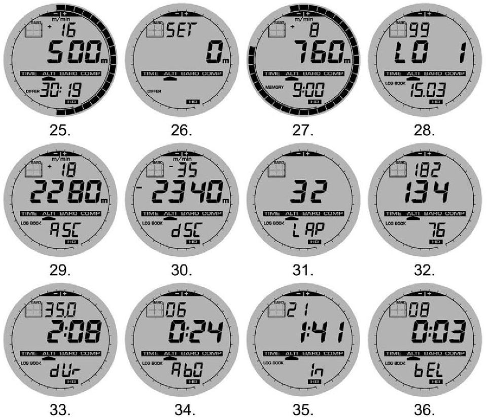
37 Note: A 10 minute recording interval means that the Wristop Computer records data every 10 minutes. 4.2 Altitude difference Measurement SUB Mode In the Altimeter mode, PRESS the [Select] button once to enter this sub mode. In the Altitude Difference measurement mode (Fig. 25): Field 1 displays the vertical ascent or descent rate; Field 2 displays the current altitude in increments of 5 meters or 10 feet depending on the unit of measure selected; and Field 3 displays the running time; to the left of the time is the text differ. The Outer Circumference graphically displays the altitude in hundreds of meters or feet over a full thousand where one complete circle is equivalent to The running time is displayed up to 39 hours and 59 minutes; after which three dashes (-:--) appear on the display in Field 3. If the user allows the difference measurement sub mode to remain on visual display continuously for 12 hours, Wristop Computer will after this period automatically return to the main time mode. This mode does continue in the background and allows the user to move to other modes. The user can return to this sub mode to view the current status at his/her convenience. Note: The difference measurement mode is a relative measurement. Any change in the reference altitude during the altitude difference measurement will effect the measured altitude. We recommend that the reference altitude always be checked and set again prior to beginning a new measurement How to Start the Altitude Difference Measurement 1. PRESS the [Select] button and hold in for 2 seconds. Located in Field 1 is the text SET ; located in Field 2, zero will begin to flash (Fig. 26). 2. PRESS the [Mode] button to accept the flashing zero and start the difference measurement. If the user does not want to set the altitude difference to zero to restart the difference measurement, PRESS either the [+] or the [-] button to return to the original altitude difference reading and then PRESS the [Mode] button to validate that reading. Note: If the user does not press any button for 1 minute in the setup mode, the display will return to the main mode without zeroing the altimeter. 30
38 hour Memory SUB Mode In the Altimeter mode, PRESS the [Select] button twice to enter this sub mode. In the 24-hour memory mode (Fig. 27): Field 1 displays the vertical ascent or descent rate; Field 2 displays the current altitude in increments of 5 meters or 10 feet, depending on the unit of measure selected ; and Field 3 displays the particular hour and to the left the text memory. The Outer Circumference displays graphically the altitude in hundreds of meters or feet over a full thousand where one complete circle is equivalent to To view the information compiled in the 24-hr memory: 1. PRESS the [-] button to scroll back down in increments of one hour and view the vertical ascent/descent rate and the altitude for that particular hour. 2. PRESS the [+] button to scroll back up. Note: Replacing the battery will not erase this information. 4.4 Logbook SUB Mode In the Altimeter mode, PRESS the [Select] button three times to enter this sub mode. In the logbook mode, nine summarizing displays are shown. The displays automatically rotate showing the first display for 7 seconds then proceeds to show the next displays at 4 second intervals. In the first display (Fig. 28): Field 1 displays the year; Field 2 displays the text LO with the current logbook number flashing; and Field 3 displays the month and day of the particular logbook number. To the left of the month/day, is the text Log Book. The user can PRESS the [-] to scroll down to view previous logs captured and then PRESS [+] to scroll up to view the most current logbook. The second display shows the ascent information for the particular logbook that is being viewed (Fig. 29). 31
INSTRUCTION MANUAL CUSTOMER SERVICE CONTACTS
 INSTRUCTION MANUAL CUSTOMER SERVICE CONTACTS EN Suunto Oy Phone +358 9 875870 Fax +358 9 87587301 Suunto USA Phone 1 (800) 543-9124 Canada Phone 1 (800) 776-7770 European Call Center Phone +358 2 284 11
Suunto X6hr USER S GUIDE
 EN Suunto X6hr EN USER S GUIDE TABLE OF CONTENTS 1. General Information...5 1.1. Care and Maintenance...5.1.1. Care of the Suunto X6hr...5.1.2. Care of the Transmitter Belt...6 1.2. Water Resistance...6
TABLE OF CONTENTS 1. GENERAL INFORMATION...6 1.1. CHECKLIST...7 1.2. GETTING STARTED...7 1.3. SUUNTO T6 FEATURES...8 1.4. CARE AND MAINTENANCE...
 EN CUSTOMER SERVICE CONTACTS Global Help Desk +358 2 284 11 60 Suunto USA Phone +1 (800) 543-9124 Canada Phone +1 (800) 776-7770 Suunto website www.suunto.com COPYRIGHT This publication and its contents
1. INTRODUCTION TO SUUNTO SMART BELT 2. GETTING STARTED WITH SUUNTO SMART BELT
 EN TABLE OF CONTENTS 1. INTRODUCTION TO SUUNTO SMART BELT... 3 2. GETTING STARTED WITH SUUNTO SMART BELT... 3 3. DOWNLOADING AND ANALYZING DATA RECORDED WITH SUUNTO SMART BELT... 7 4. ERRORS AND WARNINGS...
SUUNTO COMFORT BELT Heart Rate Transmitter Belts USER GUIDE
 en SUUNTO COMFORT BELT Heart Rate Transmitter Belts USER GUIDE 1 Introduction to Suunto Comfort Belt................................................. 3 2 Getting started with Suunto Comfort Belt............................................
SUUNTO CORE USER GUIDE
 SUUNTO CORE USER GUIDE en 1 SAFETY........................................................................ 5 Types of safety precautions:.......................................... 5 Safety precautions:....................................................
AERIS F10. Watch Free Dive Gauge. Operating Manual. (cover art provided separately)
") AERIS F10 Watch Free Dive Gauge Operating Manual (cover art provided separately) CONTENTS WARRANTY, NOTICES... 6 NOTICE - STORAGE AND INITIAL ACTIVATION... 7 FULL LCD... 8 INTRODUCTION AND GENERAL FEATURES
AERIS F10 Watch Free Dive Gauge Operating Manual (cover art provided separately) CONTENTS WARRANTY, NOTICES... 6 NOTICE - STORAGE AND INITIAL ACTIVATION... 7 FULL LCD... 8 INTRODUCTION AND GENERAL FEATURES
Regatta Master Watch_W012. Watch Instructions
 Regatta Master Watch_W012 Watch Instructions This watch comes with a 2 year warranty. For warranty issues please contact your nearest stockist. Proof of purchase required. 1.0 Introduction The watch is
Mini Digital Altimeter & Climb rate & Barometer & Thermometer & Compass & Weather forecast & Time
 Mini Digital Altimeter & Climb rate & Barometer & Thermometer & Compass & Weather forecast & Time User Manual 1.Introduction Thank you for purchase of Mini Digital Altimeter. This mini digital atimeter
VERTECH II OPERATION AND SETUP SKI FEATURES SKI AND ALPIN OPERATION
 Ft Ft VERTECH II SKI AND ALPIN ADJUST OPERATION AND SETUP START/ STOP ADJUST SKI FEATURES V E R T A L T I USA Records vertical meters skied Counts number of runs skied aximum, current, and average rate
Quick Guide. S610i S610i
 COMPLETE HR Displays your heart rate as bpm and % of HR max, average heart rate and exercise duration. Allows you to set 5 exercise sets for interval training with HR target zones and recovery calculation.
HOW TO START THE E600 HEART RATE MONITOR
 E 600 man kansi USA C 19.11.2002 15:28 Page 1 HOW TO START THE E600 HEART RATE MONITOR Start from the Time of Day screen. Polar Electro Inc. 370 Crossways Park Drive Woodbury, NY 11797-2050 U.S.A. Polar
VIBRATION WATCH with:
 Vibration Alarm won't disturb others. Beep Alarm option VIBRATION WATCH with: Auto Reload Countdown Timer can be set for seconds, minutes & hours. Use for reminders such as medical conditions, medication,
SUUNTO AMBIT2 USER GUIDE
 SUUNTO AMBIT2 USER GUIDE en 1 SAFETY........................................................................ 7 2 Welcome...................................................................... 9 3 Display
MODES & VIEWS Time Training Speed & Distance
 en USER GUIDE 1 2 MODES & VIEWS Time Training Speed & Distance weekday date seconds dual time empty training effect calories average heart rate lap time time distance average speed maximum speed lap time
SUUNTO AMBIT3 PEAK 2.0 USER GUIDE
 SUUNTO AMBIT3 PEAK 2.0 USER GUIDE 2 1 SAFETY... 6 2 Getting started... 8 2.1 Buttons and menus... 8 2.2 Set up... 9 2.3 Adjusting settings... 12 3 Features... 14 3.1 Activity monitoring... 14 3.2 Alti-Baro...
06MAR THU 12:38.28. User Manual
 06MAR THU 12:38.28 88.2% 28.0C User Manual 1.0 General Guide Thank you for purchasing your new ADC. We recommend reading this manual, and practicing the operations before using your ADC in the field. The
SUUNTO AMBIT2 2.0 USER GUIDE
 SUUNTO AMBIT2 2.0 USER GUIDE 2 1 SAFETY... 6 2 Display icons and segments... 8 3 Using buttons... 9 3.1 Using backlight and button lock... 11 4 Getting started... 12 5 Customizing your Suunto Ambit2...
Fox 40 Whistle Watch USER MANUAL 609-0700
 Fox 40 Whistle Watch USER MANUAL 609-0700 CONTENTS BUTTONS AND FEATURES... 3 OPERATING THE WATCH... 4 STOPWATCH MODE... 5 COUNTDOWN MODE... 6 ALARM MODE... 7 BATTERY REPLACEMENT... 8 CARE AND MAINTENANCE...
OARTEC SIMULATOR TRAINING MONITOR USER MANUAL Version 1.05
 OARTEC SIMULATOR TRAINING MONITOR USER MANUAL Version 1.05 Contents Features Getting Started Technical Functions Software Updates Training Modes Just Row Mode Time and Distance Workouts Workout Memory
T-TOUCH EXPERT User s Manual
 T-TOUCH EXPERT User s Manual Acknowledgements We would like to thank you f choosing a TISSOT watch, a Swiss brand among the most highly renowned in the wld. Your T-TOUCH watch has the most recent technical
SUUNTO M1/M2 USER GUIDE
 SUUNTO M1/M2 USER GUIDE en 1 SAFETY........................................................................ 4 Types of safety precautions:.......................................... 4 Safety precautions:....................................................
1 Getting started... 3 1.1 Basic settings... 3 1.2 Modes and views... 4 1.3 Menu navigation... 5 2 Training with your heart rate monitor... 7 2.
 en QUICK GUIDE 1 2 1 Getting started......................................................................... 3 1.1 Basic settings............................................................... 3 1.2 Modes
Information is Power. triax c5 features
 Information is Power By measuring intensity (heart rate) and duration (time) you can avoid over training, help prevent injury, and maximize your chances of achieving your goals. triax c5 features Adjustable
CUSTOMER SERVICE CONTACTS
 EN CUSTOMER SERVICE CONTACTS Global Help Desk +358 2 284 11 60 Suunto USA Phone +1 (800) 543-9124 Canada Phone +1 (800) 776-7770 Suunto website www.suunto.com COPYRIGHT This publication and its contents
Smart Apnea Computer. Instruction Manual
 Instruction Manual Smart Apnea Computer Smart Apnea Computer TABLE OF CONTENTS 1. INTRODUCTION 3 1.1. OPERATING MODES 3 1.2. USER-REPLACEABLE BATTERY 3 1.3. CONNECTING SMART APNEA TO A PC OR MAC 3 1.4.
1 Getting started... 3 1.1 Basic settings... 3 1.2 Setting activity class... 4 1.3 Menu navigation... 6 1.4 Modes and views... 7 1.5 Button lock...
 en QUICK GUIDE 1 2 1 Getting started......................................................................... 3 1.1 Basic settings............................................................... 3 1.2 Setting
SensorMaster II: Instruction Manual
 SensorMaster II: Instruction Manual roject no: 431 Version: 6.0 File name: 431MN061.CDR repared by C.K Lau Copyright: Latitude Limited Date: 8 Jan, 2003 130 mm 130 mm 90 mm saddle wire folding line Size
VIBRATION WATCH with: Vibration Alarm (won't disturb others). Beep Alarm (optional) Electro-Luminescent (EL) back light (for viewing display at
. Beep Alarm (optional) Electro-Luminescent (EL) back light (for viewing display at") VIBRATION WATCH with: Vibration Alarm (won't disturb others). Beep Alarm (optional) Electro-Luminescent (EL) back light (for viewing display at night). Second Clock (great when traveling in a different
VIBRATION WATCH with: Vibration Alarm (won't disturb others). Beep Alarm (optional) Electro-Luminescent (EL) back light (for viewing display at night). Second Clock (great when traveling in a different
SUUNTO D4I USER GUIDE
 SUUNTO D4I USER GUIDE 2 1 Safety... 5 2 Getting started... 11 2.1 Display states and views... 11 2.2 Set up... 11 2.3 Icons... 12 2.4 Software version check... 13 3 Features... 15 3.1 Activation and pre-checks...
SUUNTO QUEST USER GUIDE
 SUUNTO QUEST USER GUIDE en 1 SAFETY........................................................................ 5 Types of safety precautions:.......................................... 5 Safety precautions:....................................................
Caseback markings. w MB 119 CAL 0T10 SR927W. Accurist Watches Logo Model Number Calibre Number Battery Number
 Caseback markings w MB 119 CAL 0T10 SR927W Accurist Watches Logo Model Number Calibre Number Battery Number How to use these instructions This booklet contains setting instructions for the Accurist Chronograph
Phoenix Body Fat Scale Manual
 Phoenix Body Fat Scale Manual Low Batteries & bad battery connections are the #1 cause of scale malfunction and inaccuracy! We test all of our scale returns from consumers. Fully 60% of consumer returns
For more detailed information, see your Vantage Vue Console manual.
 For more detailed information, see your Vantage Vue Console manual. Current Weather Mode Moon phase, alarm & forecast icons Wind Rose Compass Antenna icon shows active transmission Graph of selected variable
Interactive guide online at www.victorinoxswissarmy.com
 1 4 7 2 5 8 3 6 9 Interactive guide online at www.victorinoxswissarmy.com 2 VICTORINOX SWISS ARMY INSTRUCTIONS FOR USE I. GENERAL INFORMATION Disposal of used batteries 3 Water resistance 4 Meter/bar correlation
PULSAR ANALOGUE QUARTZ WATCH WITH WORLD TIME, ALARM AND CHRONOGRAPH
 1 2 PULSAR ANALOGUE QUARTZ WATCH WITH WORLD TIME, ALARM AND CHRONOGRAPH Cal. N94J FEATURES This is a multi-functional watch featuring the world time, alarm and chronograph. The mode changes simply by turning
GBR. Polar Accurex Plus HEART RATE MONITOR USER'S MANUAL
 GBR Polar Accurex Plus HEART RATE MONITOR USER'S MANUAL QUICK REFERENCE GUIDE IN MEASURE MODE FUNCTION Illuminate the display Turn the sound signal off/on Stop/start the stopwatch BUTTON SIGNAL/LIGHT SIGNAL/LIGHT
EX 2. User Manual NM-704.1. www.newbalance-watch.com
 EX 2 901 User Manual NM-704.1 www.newbalance-watch.com 1 Design of the Watch Thank you for purchasing this watch. Please read this manual thoroughly before using the watch! [EL] EL Button To turn on the
Reference Guide. Vantage PRO2 Quick
 3465 Diablo Avenue, Hayward, CA 94545-2778 U.S.A. 510-732-9229 Fax: 510-732-9188 E-mail: info@davisnet.com www.davisnet.com Vantage PRO2 Quick Reference Guide Part Number: 07395.235 Rev C (1/6/2012) 2012
Atomic Alarm Clock Instruction Manual
 Atomic Alarm Clock Instruction Manual Introduction: Congratulations on purchasing the Atomic Alarm Clock with WWVB Radio controlled time, calendar, 12/24 hours display, time zone with US map, indoor temperature
LIMITED TWO-YEAR WARRANTY For details, refer to the Product Warranty Registration Card provided.
 LIMITED TWO-YEAR WARRANTY For details, refer to the Product Warranty Registration Card provided. COPYRIGHT NOTICE This manual is copyrighted, all rights are reserved. It may not, in whole or in part, be
Quick Guide. S720i /S710i HEART RATE MONITOR HEART RATE MONITOR
 COMPLETE HR Displays your heart rate as bpm and % of HR max, average heart rate and exercise duration. Quick Guide Allows you to set 5 exercise sets for interval training with HR target zones and recovery
Performance Watch User Guide
 W-188 589-095006 NA p e r f o r m a n c e w a t c h u s e r g u i d e BODYLINK SYSTEM Performance Watch User Guide English page 1 Français page 81 Español página 159 Português página 239 2005 Timex Corporation
G-PORTER. Portable GPS Tracker GP-102 User s Manual
 G-PORTER Portable GPS Tracker GP-102 User s Manual Chapter 1 GP-102 Overview The GP-102 is the best available portable GPS tracker and sports analyzer with the most functions with the simplest operations.
quick start manual FR60 SPORT WATCH WITH WIRELESS SYNC
 quick start manual FR60 SPORT WATCH WITH WIRELESS SYNC Warning: Always consult your physician before you begin or modify any exercise program. See the Important Safety and Product Information guide in
F O R E R U N N E R 6 1 0. q u i c k s t a r t m a n u a l
 F O R E R U N N E R 6 1 0 q u i c k s t a r t m a n u a l Important Information warning Always consult your physician before you begin or modify any exercise program. See the Important Safety and Product
Solution 862 Operators Manual. Issue 1.00
 Solution 862 Operators Manual Issue 1.00 Solution 862 Operators Manual Copyright 1998 by Electronics Design and Manufacturing Pty Limited, SYDNEY, AUSTRALIA Document Part Number MA406O Document Issue
WIRELESS FORECAST STATION
 Model: 308-1451 Instruction Manual DC: 072915 WIRELESS FORECAST STATION Table of Contents INITIAL SETUP... 2 LCD FFEATURES... 3 BUTTONS... 3 SET TIME, DATE, ETC.... 4 BACKLIGHT... 6 CITY SELECTION-SUNRISE/SUNSET
GPSMAP 62 series quick start manual. For use with the GPSMAP 62, 62s, 62st, 62sc, and 62stc
 GPSMAP 62 series quick start manual For use with the GPSMAP 62, 62s, 62st, 62sc, and 62stc Getting Started warning See the Important Safety and Product Information guide in the product box for product
wireless wireless wireless count log ready BIKE COMPUTER
 EN DIGITAL wireless DIGITAL wireless DIGITAL wireless count log SPORT ready BIKE COMPUTER 5.o Contents ROX 5.0 Contents 1 Functions and packaging contents... 7 1.1 Foreword... 7 1.2 Packaging contents...
INSTALLING A/C ADAPTER
 WS 6502 INTRODUCTION 1. SNOOZE/LIGHT BUTTON 2. BASE 3. ALM SET BUTTON 4. + / C/F BUTTON 5. HISTORY BUTTON 6. MODE BUTTON 7. CHANNEL BUTTON 8. - / RCC BUTTON 9. MAX/MIN BUTTON 10. BATTERY COMPARTMENT 11.
AGRI-ALERT 800T / AGRI-ALERT 800 ALARM SYSTEM USER MANUAL
 AGRI-ALERT 800T / AGRI-ALERT 800 ALARM SYSTEM USER MANUAL Manufacturer: Viatron Electronics 3514 1st Street, St-Hubert (Quebec) Canada J3Y 8Y5 WARNING: the warranty can be void if the Agri-Alert 800T or
STRAPLESS HEART RATE MONITOR
 INSTRUCTION MANUAL STRAPLESS HEART RATE MONITOR Model: HR-210 ENGLISH table TABLE of OF CONTENTS Before using the Monitor Introduction... 3 Important Safety Information...4 Operating the Device...4 Care
CITIZEN QUARTZ ALARM CHRONOGRAPH. Model No. AI3XXX Cal. No. 6870 INSTRUCTION MANUAL CTZ-B6813
 CITIZEN QUARTZ ALARM CHRONOGRAPH Model No. AI3XXX Cal. No. 6870 2. Mode (Display Function) Switching This watch is equipped with 8 modes consisting of time, alarm 1, alarm 2, chronograph, 0-position check,
INSTRUCTION MANUAL. Heart Rate Monitor. Model: HR-100C ST/SP SET MODE TIME
 INSTRUCTION MANUAL Heart Rate Monitor Model: HR-100C ST/SP SET MODE TIME CONTENTS Before Using the Unit Introduction... 3 Important Safety Information... 4 Physical condition and workout... 7 Training
SUUNTO DX USER GUIDE
 SUUNTO DX USER GUIDE 2 1 Safety... 5 2 Getting started... 11 2.1 Display states and views... 11 2.2 Icons... 11 2.3 Set up... 13 2.4 Software version check... 14 3 Features... 16 3.1 Activation and pre-checks...
WIRELESS MULTI-ZONE DIGITAL WEATHER CENTER. Model No. 91905 User s Manual
 WIRELESS MULTI-ZONE DIGITAL WEATHER CENTER Model No. 91905 User s Manual BASE STATION REMOTE SENSOR FEATURES AND SPECIFICATIONS BASE STATION Indoor / wireless outdoor temperature, C / F selectable Indoor
CONTENTS ABREVIATIONS/TERMS...7 WARRANTY, NOTICES, MODEL...8
 CONTENTS ABREVIATIONS/TERMS...7 WARRANTY, NOTICES, MODEL...8 FEATURES/FUNCTIONS AND WATCH MODE...9 DISPLAY LAYOUT...10 OVERVIEW...11 MENU SYSTEM...12 BACKLIGHT...13 AUDIBLE ALARM...14 PC INTERFACE...16
2.4 GHz Dual Handset Cordless Telephone Answering System 2255 with Caller ID/Call Waiting
 USER S MANUAL Part 2 2.4 GHz Dual Handset Cordless Telephone Answering System 2255 with Caller ID/Call Waiting Please also read Part 1 Important Product Information AT&T and the globe symbol are registered
HOBOmobile User s Guide Android
 HOBOmobile User s Guide Android Onset Computer Corporation 470 MacArthur Blvd. Bourne, MA 02532 www.onsetcomp.com Mailing Address: P.O. Box 3450 Pocasset, MA 02559 3450 Phone: 1 800 LOGGERS (1 800 564
ALTIMETER 50 ALTIMETER 50 F U N C T I O N S F U N C T I O N S
 Displays current altitude within 10 feet/4 meters. Records trip and total climb or descent (pat. pending). Measures 12 different performance factors for precise training. Posi-Click buttons & large display.
Solution-16 Operators Manual ISSUE 1.60
 Solution-16 Operators Manual ISSUE 1.60 !"#$%&"'()*+ Operators Manual Copyright 2002 by, SYDNEY, AUSTRALIA Document Part Number MA880O DOCUMENT ISSUE 1.60 Printed 22 March 2002 This documentation is provided
Digital Heart Rate Monitor
 W-246 811-095000-02 NA 2008 Timex Group, USA, Inc. TIMEX and NIGHT-MODE are registered trademarks of Timex Group USA, Inc. INDIGLO is a registered trademark of Indiglo Corporation in the US and other countries.
Polar FS1/FS2c/FS3c. User Manual
 Polar FS1/FS2c/FS3c User Manual Dear Customer, Congratulations on your purchase of a new Polar FS1/FS2c/FS3c Fitness Heart Rate Monitor! This manual contains the information you need to use and maintain
User Manual of WT 493
 User Manual of WT 493 Introduction Congratulations on your purchase of this smart unit. This unit can be used as a radio to catch the latest news and enjoy the beautiful music; it can also be used as an
Polar Cardio GX: Help Topics
 Polar Cardio GX: Help Topics Table of Contents The Polar Cardio GX system... 1 Quick steps... 2 PC requirements... 2 Training articles... 3 Bluetooth... 3 Introduction to hardware... 5 Base station...
ATOM 3.0 OPERATING MANUAL ATOM 3.0 DIVE COMPUTER OPERATING MANUAL
 ATOM 3.0 DIVE COMPUTER OPERATING MANUAL 2002 Design, 2011 1 CONTENTS WARRANTY, NOTICES, MODEL...3 FEATURES/FUNCTIONS AND WATCH MODE...5 DISPLAY ICONS...6 ABBREVIATIONS/TERMS...6 OVERVIEW...7 SELECTION
SUUNTO AMBIT3 SPORT 1.0 USER GUIDE
 SUUNTO AMBIT3 SPORT 1.0 USER GUIDE 2 1 SAFETY... 6 2 Getting started... 8 2.1 Buttons and menus... 8 2.2 Set up... 9 2.3 Adjusting settings... 12 3 Features... 14 3.1 Activity monitoring... 14 3.2 Autopause...
tattletale User Guide Consumer unit version 2.48 1 P a g e
 tattletale User Guide Consumer unit version 2.48 1 P a g e Contents Basic 1... 4 Base Unit Features... 4 Initial Setup... 4 Arming... 5 Disarming... 5 Quiet Button... 5 Settings... 5 Settings 2... 6 Quick
User Guide. Heavy Duty Dissolved Oxygen Meter. Model 407510
 User Guide Heavy Duty Dissolved Oxygen Meter Model 407510 Introduction Congratulations on your purchase of Extech's Heavy Duty Dissolved Oxygen / Temperature Meter which simultaneously displays Dissolved
Digital Heart Rate Monitor
 W-248 843-095002-02 EU 2009 Timex Group, USA, Inc. TIMEX, TRIATHLON and NIGHT-MODE are registered trademarks of Timex Group USA, Inc. INDIGLO is a registered trademark of Indiglo Corporation in the US
MEMO ALARM CLOCK Operating Manual
 MEMO ALARM CLOCK Operating Manual INTRODUCTION Congratulations on purchasing this state-of-the-art Alarm clock with radio controlled time. The operation of this product is simple and straightforward and
quick reference guide Edge 605/705 GPS-ENABLED BIKE COMPUTER
 quick reference guide Edge 605/705 GPS-ENABLED BIKE COMPUTER MB Warning: This product contains a lithium-ion battery. See the Important Safety and Product Information guide in the product box for important
TOUCH SCREEN WEATHER STATION (WIND AND AIR PRESSURE) WH-1080PC. Operation Manual
 WH-1080PC. Operation Manual") TOUCH SCREEN WEATHER STATION (WIND AND AIR PRESSURE) WH-1080PC Operation Manual About this manual Thank you and congratulations on selecting this professional weather station! We are positive you will
TOUCH SCREEN WEATHER STATION (WIND AND AIR PRESSURE) WH-1080PC Operation Manual About this manual Thank you and congratulations on selecting this professional weather station! We are positive you will
Talking Atomic Alarm Clock Instructions
 1 Talking Atomic Alarm Clock Instructions S1 (Talking+Snooze+Back Light) S2 (Alarm Time + Alarm Hour) S4 (Alarm Volume + OFF) S3 (Alarm ON/OFF + Alarm Minute) S5 (Wave, Manual Signal Reception) S8 (DST
IDS X-Series User Manual 700-398-01D Issued July 2012
 1 2 Contents 1. Introduction to the IDS X-Series Panels... 7 2. Before Operating Your Alarm System... 7 3. Understanding the Keypad LEDs... 8 3.1 Viewing Data on an LED Keypad... 12 3.1.1 LED Status Indicators...
Weather Radio Alarm Clock
 1200093 User s Guide Weather Radio Alarm Clock Thank you for purchasing your Weather Radio Alarm Clock from RadioShack. Please read this user s guide before installing, setting up, and using your new weather
Water Tank Level Monitor
 Water Tank Level Monitor INSTRUCTION MANUAL MODEL NO: WTL001 Table of Contents 1. INTRODUCTION... 2 1.1 Package Contents... 2 1.2 Features... 2 2. INSTALLATION... 3 2.1 Water Tank Sensor Battery Installs...
GPSMAP 62 series quick start manual. For use with the GPSMAP 62, 62s, and 62st
 GPSMAP 62 series quick start manual For use with the GPSMAP 62, 62s, and 62st Getting Started warning See the Important Safety and Product Information guide in the product box for product warnings and
GPSMAP 78 series. quick start manual. for use with the GPSMAP 78, GPSMAP 78s, and GPSMAP 78sc
 GPSMAP 78 series quick start manual for use with the GPSMAP 78, GPSMAP 78s, and GPSMAP 78sc Getting Started warning See the Important Safety and Product Information guide in the product box for product
GPSMAP 62 series quick start manual. For use with the GPSMAP 62, 62s, 62st, 62sc, and 62stc
 GPSMAP 62 series quick start manual For use with the GPSMAP 62, 62s, 62st, 62sc, and 62stc Getting Started warning See the Important Safety and Product Information guide in the product box for product
Cycle Trainer 2.0 GPS USER MANUAL
 Cycle Trainer 2.0 GPS USER MANUAL Table of Contents Introducing Your Cycle Trainer 2.0...4 Features...4 Charging the Cycle Trainer...4 Basic Operation...5 Icon Descriptions...5 Getting Started...6 Installing
G1 GPS Sensor User Manual
 G1 GPS Sensor User Manual 1. 2. 3. 4. 5. A B Congratulations! You are now the proud owner of a Polar G1 GPS sensor. Polar G1 provides speed and distance data in all outdoor sports using Global Positioning
FR 70 owner s manual. January 2013 190-01373-00 Rev. B Printed in Taiwan
 FR 70 owner s manual January 2013 190-01373-00 Rev. B Printed in Taiwan 2011 2013 Garmin Ltd. or its subsidiaries All rights reserved. Under the copyright laws, this manual may not be copied, in whole
SUUNTO ZOOP USER S GUIDE
 EN SUUNTO ZOOP USER S GUIDE Quick reference guide ZOOP Arrows: - Decompression Stop at the Ceiling Depth - Mandatory Safety Stop Zone - Ascent Recommended - Must Descend Present Depth Dive Counter Logbook
Intelli-Time Alarm Clock model 13027
 Instruction Manual Intelli-Time Alarm Clock model 13027 CONTENTS Unpacking Instructions... 2 Package Contents... 2 Product Registration... 2 Features & Benefits... 3 Clock Setup... 4 Intelli-Time Clock...
ENGLISH ANALOG. 2 Hand Analog K62-132. 2 Hand Analog. 3 Hand Analog VX51E / R1063.2 / 9T33. Palindrome Too
 ANALOG ENGLISH 2 Hand Analog K62-132 Time Setting 1. Push button to move hands. 2. Set to correct time. FRONT BACK PUSHER BUTTON FOR TIME ADJUSTMENT 2 Hand Analog Time Setting 1. Pull crown out to position
TOUCH SCREEN WEATHER STATION MODEL WS-3500. Operation Manual
 TOUCH SCREEN WEATHER STATION MODEL WS-3500 Operation Manual 28 Table of Contents 1... General 2... Important Touch Screen Operating Notes generally applicable 3... Putting into Operation 3.1... Wiring
Instructional videos are posted at: http://www.youtube.com/timexusa
 V.16 Table of Contents Introduction...3 Features Overview...3 Charge Your Run Trainer Watch...4 Get the Latest Firmware...4 Create a Free Timex Online Account...4 Configure the Watch...4 Pairing ANT+ Sensors
Model: 308-1412 Manual DC: 080215 WIRELESS COLOR FORECAST STATION
 Model: 308-1412 Manual DC: 080215 WIRELESS COLOR FORECAST STATION FRONT VIEW SENSOR TX141TH-Bv2 LED TX Sensor Battery Cover Sensor Battery Compartment 2 AA Buttons Battery Compartment 3 AAA BACK VIEW Battery
Radio-Controlled Projection Clock with Indoor Temperature
 Item 972483 Radio-Controlled Projection Clock with Indoor Temperature Owner s Manual Thank you for purchasing the new generation of projection clock. Designed and engineered with the state-of-art technology
532-095002. TIMEX is a registered trademark of Timex Corporation. 2003 Timex Corporation.
 532-095002 TIMEX is a registered trademark of Timex Corporation. 2003 Timex Corporation. Timex Fitness Sensors Heart Rate Sensor Speed + Distance Sensor Watches are for more than keeping time. Digital
TomTom Runner & Multi-Sport Reference Guide 1.8
 TomTom Runner & Multi-Sport Reference Guide 1.8 Contents Welcome 4 What's new 5 What's new in this release... 5 Getting started 6 Your watch 7 About your watch... 7 Wearing your watch... 7 Cleaning your
INSTRUCTION MANUAL GUeSS WATCheS
 INSTRUCTION MANUAL Guess Watches WOMENS CONGRATULATIONS ON OWNING YOUR NEW GUESS WATCH. DEVELOPED FROM ADVANCED ELECTRONICS TECHNOLOGY, THE MOVEMENT IS MANUFACTURED FROM Congratulations THE BEST QUALITY
SUUNTO AMBIT2 S 2.0 USER GUIDE
 SUUNTO AMBIT2 S 2.0 USER GUIDE 2 1 SAFETY... 6 2 Display icons and segments... 8 3 Using buttons... 9 3.1 Using backlight and button lock... 11 4 Getting started... 12 5 Customizing your Suunto Ambit2
EDGE 500 GPS-ENABLED CYCLING COMPUTER. owner s manual
 EDGE 500 GPS-ENABLED CYCLING COMPUTER owner s manual 2010 Garmin Ltd. or its subsidiaries Garmin International, Inc. 1200 East 151st Street, Olathe, Kansas 66062, USA Tel. (913) 397.8200 or (800) 800.1020
User's Guide. Pinless Moisture Meter. Model MO257
 User's Guide Pinless Moisture Meter Model MO257 Introduction Congratulations on your purchase of the Extech MO257 Pinless Moisture Meter. The pinless moisture sensor monitors the moisture in wood and other
SUUNTO AMBIT3 SPORT 2.0 USER GUIDE
 SUUNTO AMBIT3 SPORT 2.0 USER GUIDE 2 1 SAFETY... 6 2 Getting started... 8 2.1 Buttons and menus... 8 2.2 Set up... 9 2.3 Adjusting settings... 12 3 Features... 14 3.1 Activity monitoring... 14 3.2 Autopause...
Goal Status Bar. Time/Date. Activity type: distance calories steps. Activity value. Quick Start Guide
 Goal Status Bar Time/Date Activity type: distance calories steps Activity value Quick Start Guide TO TURN YOUR C300 ON: press & hold any button until the screen turns on. Press to change modes: Time Hourly
owner s manual FORERUNNER 50 with ANT+Sport wireless technology
 owner s manual FORERUNNER 50 with ANT+Sport wireless technology 2007 Garmin Ltd. or its subsidiaries Garmin International, Inc. Garmin (Europe) Ltd. 1200 East 151st Street, Liberty House, Olathe, Kansas