MAGNAMAX VOLTAGE REGULATOR TECHNICAL MANUAL MODELS PM100 AND PM200
|
|
|
- Merilyn Parrish
- 7 years ago
- Views:
Transcription


1 MAGNAMAX VOLTAGE REGULATOR TECHNICAL MANUAL MODELS PM100 AND PM200 1
2 SECTION 1 -INTRODUCTION...5 GENERAL DESCRIPTION...5 SPECIFICATIONS...5 FEATURES...6 Sensing Voltage...6 Loss of Sensing...6 Underfrequency...6 Overexcitation...6 Paralleling...8 Overtemperature Protection...8 Field Current Limit...8 Generator Current Limit (Model PM200 Only)...8 Environmental Protection...8 EMI Suppression...8 SECTION 2- THEORY OF OPERATION...9 MAIN REGULATOR...9 PROTECTIVE FEATURES...11 PARALLELING CIRCUIT...11 SECTION 3 - INSTALLATION...12 MOUNTING...12 INTERCONNECTIONS...13 Remote Voltage Adjust...13 Sensing Voltage...14 Power Output...14 Power Input...14 Paralleling Input...14 Generator Current Limit...15 Field Flashing...15 SECTION 4 - ADJUSTMENTS & STARTUP PROCEDURES...16 GENERAL...16 VOLTAGE ADJUSTMENTS...17 STABILITY ADJUSTMENT...17 UNDERFREQUENCY ADJUSTMENT...18 DROOP ADJUSTMENT
3 GENERATOR CURRENT LIMIT ADJUST (MODEL PM200 ONLY)...20 SECTION 5 - TROUBLESHOOTING...21 SYMPTOM...21 Residual Voltage Output...21 (No Buildup)...21 Output Voltage Low...22 Voltage does not increase as Coarse Voltage is turned clockwise...22 Output Voltage High...22 Poor Voltage Regulation...22 Output Voltage High -No Adjustment...23 Remote Voltage Control Operates Backwards...23 Generator Voltage Hunting...23 Underfrequency LED on Overexcitation LED on...23 Field Limit LED on...23 No Droop Control or Negative Droop (Generator does not share load.)...24 Generator Current Limit LED on. (PM200 Models Only)...24 Generator Fault Current Limited to Undesired Level SECTION 6 - FIELD APPLICATIONS...24 MANUAL VOLTAGE CONTROL...24 VAR-POWER FACTOR CONTROLLER...24 SECTION 7- DRAWINGS AND DIAGRAMS...25 Outline Drawing of Regulator...25 Typical Connection - Three Phase Sensing ( Volts)...26 Typical Connection - Three Phase Sensing ( Volts) with Reactive Droop Paralleling...27 Typical Connection - Single Phase Sensing ( Volts)...28 Typical Connection - Single Phase Sensing ( Volts) with Reactive Droop Paralleling...29 Typical Connection - Three Phase Sensing ( Volts)...30 Typical Connection - Three Phase Sensing ( Volts) with Reactive Droop Paralleling...31 Typical Connection - Three Phase Sensing ( Volts) with Reactive Differential Paralleling...32 Typical Connection - Three Phase Sensing ( Volts) with Generator Current Limit
4 4
5 SECTION 1 -INTRODUCTION GENERAL DESCRIPTION The MagnaMax Voltage Regulator is a sealed electronic voltage regulator which controls the output of a brushless ac generator by regulating the current into the exciter field. Unlike most regulators, the input power is from a multi-pole high frequency permanent magnet generator (PMG) incorporated within the main generator assembly. SPECIFICATIONS Sensing Sensing Mode Input Requirements Output Power Continuous Max Forcing (1-mm.) 60 Hz Vac 50 Hz Vac RMS (Single or ThreePhase) 300 Hz Vac 250 Hz Vac 75 Vdc at 3.0 Adc 170 Vdc at 7.5 Adc Nominal Hot Field Resistance ohms Regulation.5% Regulator Response Less than 10 milliseconds Remote Voltage Adjust Current Operating Ambient Temperature Storage Temperature Less than 10 milliamps -40 C to +70 C -40 C to +85 C Size 9.5L x 6.0W x 3.2H (24.1 cm x 15.2 cm x 8.13 cm) Weight 5.5 Lbs. (2.5 Kg) Fuse Size and Type 25 x amp Littelfuse or Bussman ABC-S Power Dissipation 12 watts (continuous) 22 watts (forcing) 5
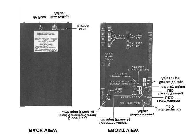
6 FEATURES Sensing Voltage The voltage regulator is equipped for either 3-phase or 1-phase sensing. The sensing voltage is continuously adjustable over the entire voltage range with the 15 turn coarse voltage adjust control (Figure 1). The single turn fine voltage adjust control gives a minimum of ±10% voltage variation at any setting of the coarse adjust. A 10,000 ohm optional remote rheostat can be added. This remote rheostat can also give a ±10% variation independent of the coarse adjust setting. Loss of Sensing If an open circuit occurs in one of the sensing leads (or if the E2-E3 Jumper is not properly connected when using single phase sensing), the regulator will turn off and the loss of sensing LED will turn on (Figure 1). At this time, the generator output voltage will go to residual. The regulator will automatically reset when proper sensing is restored. This loss of sensing circuit will not activate under a generator short circuit condition but rather the regulator will turn to its full forcing capabilities for a minimum of 10 seconds for fault clearing. CAUTION: Whenever a potential transformer is used for sensing, a break on the primary side of the transformer will cause maximum forcing from the regulator, and the loss of sensing circuit will not activate. Underfrequency The underfrequency control (Figure 1) changes the regulator s mode of operation. When not operating in the underfrequency mode, the regulator has a flat regulation, constant voltage over a frequency range. When operating in the underfrequency mode, the regulator has a constant volts per hertz characteristic (a linear relationship of voltage with respect to frequency). The transition frequency is adjustable from 40 Hz to 70 Hz (Figure 2A, 2B, and 2C for typical volts/hertz characteristics). Overexcitation The overexcitation circuit senses when the regulator output voltage is above a set level. If this voltage remains above that level, the overexcitation LED (Figure 1) will turn on and a protective function with an inverse time characteristic turns the regulator off. The generator voltage will go to a residual level and the overexcitation LED (Figure 1) will remain lit. The generator must be stopped or input power must be removed for a minimum of 10 seconds to reset the circuit and restore normal operation. 6
7 Figure 2 A Approximate slopes and maximum range of the underfrequency adjustment features are shown. Figure 2 B The typical underfrequency volts per hertz slope as set at the factory at 60 Hz is illustrated. Figure 2 C The typical underfrequency volts per hertz slope as set at the factory at 50 Hz is illustrated. 7
8 Paralleling Provisions are included in the regulator to allow paralleling using either reactive droop or reactive differential (cross current) compensation with the addition of an external 5 amp, 5 VA current transformer. Overtemperature Protection The regulator will turn itself off before overheating damages it. This will occur at an ambient temperature in excess of 70 C. The generator voltage will go to a residual level and both the overtemperature LED and the field current limit LED (Figure 1) will turn on and remain lit. When the regulator cools it will automatically return to normal operation. Field Current Limit The regulator output is current limited. Should a heavy current load or short circuit occur across the field output terminals (Figure 1) the regulator switches to a current limit condition and the field limit LED (Figure 1) will turn on. The limiting circuit automatically resets itself when the output current drops below the current limit set point. This current limit set point is not adjustable. Generator Current Limit (Model PM200 Only) The generator current limit is designed to control the maximum short circuit current that will be sustained by the generator (Figure 1). Current sensing is through external 5 amp, 5 VA current transformers. Depending upon the current transformer ratio, the regulator will limit the generator current from about 150% to about 400% Isolation is provided on the regulator inputs so any conventional current transformer interconnections typically used in meter panels or switchgear are acceptable. For adjustment procedures on these features, see Adjustments and Startup Procedures. Environmental Protection The MagnaMax Voltage Regulator is a totally encapsulated design to limit application problems even in harsh environments. The ability of the regulator to withstand harsh environments has been illustrated through hundreds of hours of salt fog tests (ASTM B117-73), humidity tests (MIL-STD705B Method 711-1C), thermal cycles (-40 C to+70 C), shock tests (5 G s in all three planes), and vibration tests (.035 in. at Hz). EMI Suppression The standard regulator meets Mil-STD 461 B part 9 for conducted and radiated emissions when mounted in the generator conduit box. 8
9 SECTION 2- THEORY OF OPERATION MAIN REGULATOR There are four basic function blocks to the MagnaMax Voltage Regulator. These blocks are the sensing input circuit, the main summing amplifier, the pulsed driver circuit, and the power output switching circuit (Figure 3A). FIGURE 3A PM100 and PM200 Block Diagram The generator voltage is fed into a circuit that calculates the RMS value of the incoming signal. A feedback resistor controls the magnitude of the output. The output signal varies as this feedback resistor is adjusted. This adjustable feedback resistor is the coarse voltage adjust. The output from the sensing circuit is then fed to the main summing amplifier. As the name implies, signals from the protective circuits as well as the external fine voltage adjust and the remote voltage adjust are combined at this point. This combined signal is then passed to the driver circuit. 9
10 The driver circuit converts the signal from the main summing amplifier to gate pulses that control the output power FET (Field Effect Transistor). The power FET controls the current to the exciter field. The longer the pulse to the gate of the FET, the greater the generator output voltage. Conversely the shorter the pulse to the gate of the FET, the shorter the current pulse to the exciter field and the lower the generator voltage. These four circuits are tied together with one feedback circuit to make the regulator selfcontrolling. This is the function of the stability circuit. The stability circuit senses both exciter field current and exciter field voltage. The adjustable signal output is fed back to one of the inputs of the main summing amplifier. As load is applied, the generator voltage tends to decrease. The stability circuit increases the control signal thereby increasing the exciter field current and the output voltage. As the generator voltage increases, the stability circuit decreases the feedback signal. Adjusting the stability control changes the response time of the regulator thereby obtaining the best match for any particular generator (Figure 3B). FIGURE 3B Transient voltage response at various stability settings 10
11 PROTECTIVE FEATURES There are six protection features (Figure 3A): (1) loss of sensing, (2) underfrequency, (3) overexcitation, (4) overtemperature, (5) field current limit, and (6) generator current limit (model PM200 only). 1. The loss of sensing circuit monitors continuity in the sensing leads. If any of these leads should open an LED is lit and a signal is sent to the main summing amplifier that turns the regulator off. Reconnecting the sensing lead will automatically reset the regulator and restore normal operation 2. The underfrequency circuit operates when the generator frequency drops below the adjustable set point (See Adjustments and Startup Procedures for proper adjustment). An LED is lit and a voltage signal proportional to frequency is sent to the main summing amplifier. 3. The overexcitation circuit monitors the regulator output voltage. If this voltage exceeds a preset value an LED turns on and a timer starts to operate. After the timeout period, a signal is sent to the main summing amplifier to turn the regulator off. Input power must be disconnected from the regulator or the generator must be shutdown for a minimum of 10 seconds to reset the circuit. 4. The regulator has a thermal sensor that monitors temperature. When the ambient temperature is in excess of 70 C the regulator turns off. The regulator is automatically reset when the ambient temperature drops below 70 C. 5. The field current limit circuit continuously monitors output current. When it reaches the preset point or tries to exceed this level, pulses are sent to the driver which limits this output current. Normal operation is resumed when the output current drops below the present value. 6. The generator current limit circuit (available on PM200 models only) receives a signal from three generator current transformers (See Figure 1 for location of input terminals and adjustment control). (The paralleling terminals are the inputs for one of the current transformers.) Each current signal is converted to a voltage signal and combined. Its composite is then sent to the main summing amplifier. The amount of control signal is determined by the setting of the current limit adjustment (See Section 4 for proper adjustment). PARALLELING CIRCUIT The paralleling input requires a current signal from a 5 amp 5 VA current transformer. The current signal is converted to a voltage signal, amplified, and fed into the RMS sensing circuit. The gain control of the voltage amplifier is the droop adjustment. (For instructions on connecting the paralleling circuit see Section 3.) 11
12 Section 3 - INSTALLATION MOUNTING The MagnaMax Voltage Regulator is normally located in the generator conduit box, but is also designed to operate in remote switchgear cabinets with convection cooling. It is equipped with two sets of mounting holes. The first set is located on the back of the regulator. These are the normal mounting holes for mounting in the generator conduit box or when the box panel assembly is moved to a remote site. If the regulator is to be remote mounted in the switchgear or auxiliary control enclosures, the second set of mounting holes can be used. This leaves both sides of the regulator accessible. (See Figure 4A and 4B for mounting hole dimensions.) FIGURE 4 A Front Mounting Hole Pattern FIGURE 4 B Side Mounting Hole Pattern The regulator can be mounted in any of the three planes. However, it is recommended that the regulator be mounted with the heat sink fins in the vertical plane. 12
13 WARNING THE REGULATOR CHASSIS MUST BE PROPERLY CONNECTED TO A SUITABLE POWER SYSTEM GROUND TO PREVENT THE POSSIBILITY OF ELECTRICAL SHOCK HAZARD. The environmental protective anodizing on the regulator case is an insulator, therefore, when mounting the regulator a secure ground must be established. One method of establishing this ground is to mount the regulator using lock washers that pierce the anodizing and connect a wire from the regulator case to the power system ground CAUTION: DO NOT megger or hi-pot the generator with the regulator connected. DO NOT megger or hi-pot the regulator. INTERCONNECTIONS For typical wiring diagrams see the Outline Drawings and Diagrams (Section 7). CAUTION: For use on generators with outputs greater than 600 V, an external potential transformer must be used for voltage sensing. Whenever a potential transformer is used for sensing, a open circuit on the primary side of the transformer will cause maximum forcing from the regulator, and the loss of sensing circuit will not activate. Assure that all connections on the primary side of the transformer are tight and secured from possible vibration. Remote Voltage Adjust If a remote voltage adjust is required, use a 10,000-ohm, 1-watt potentiometer (1-watt is the minimum power requirement needed, to minimize the effect of vibration, a 25-watt rheostat is recommended). Remove the jumper from terminals 6 and 7 and connect the remote voltage adjust to these terminals. This connection should be made using twoconductor non-shielded moderately twisted pair cable of wire gauges The remote voltage adjust cabling should be kept separated from any power or sensing leads. For applications where the remote voltage adjust will be mounted at distances greater than 35- feet from the regulator, it is recommended that the complete regulator be remotely mounted. As an alternate, the installation of a potential transformer in the regulator sensing circuit extends this distance beyond 150 feet. Finally, a motorized potentiometer can also be used. Note which terminal is connected to the wiper arm. If this is reversed, the remote control will function backwards.
14 Sensing Voltage The MagnaMax Voltage Regulator comes equipped for 3-phase sensing as standard. It can optionally be used with single phase sensing by connecting the generator sensing voltage to terminals El and E2 and installing a jumper from the second terminal E2 to terminal E3. Power Output The power output terminals of the regulator are labeled as Fl + and F2-. These terminals are connected to the Fl and F2 generator leads respectively. DO NOT ground either one of the field leads. Power Input The two power input terminals of the regulator are labeled PMG. The leads of the Permanent Magnet Generator are connected to these terminals. DO NOT ground either one of the PMG leads. WARNING THE VOLTAGE REGULATOR POWER OUTPUT TERMINALS (F1+ AND F2-) SHOULD NEVER BE DISCONNECTED DURING OPERATION. THIS CAN RESULT IN PERMANENT DAMAGE TO THE REGULATOR. IF A REGULATOR POWER SWITCH IS DESIRED, IT SHOULD BE PLACED AT THE POWER INPUT TERMINALS. Paralleling Input The MagnaMax Voltage Regulator comes with paralleling provisions, The paralleling input terminals are labeled CTB1 and CTB2. If paralleling is desired, connect the leads from a standard 5 amp 5 VA current transformer to these input terminals. The standard MagnaMax generator phase rotation is C-B-A with CCW rotation when facing the conduit box or opposite drive end. For C-B-A generator phase rotation the connection is as follows: With three phase sensing, connect generator sensing lead T1 to regulator terminal El, T2 to regulator terminal E2, and T3 to regulator terminal E3. With single phase sensing, connect generator sensing lead T1 to regulator terminal El, T3 to regulator terminal E2, and jumper regulator terminal E2 to regulator terminal E3. 14
15 For either of the above sensing connections, the paralleling transformer must be in the generator T2 lead with the H1 towards the generator and the Xl connected to the regulator CTB1 terminal. Note: If a different phase rotation is desired, it is recommended that the regulator CT connections are made as stated above and the phase rotation change is performed beyond these connections. CAUTION: The polarity and phasing of the current transformer and sensing connections must be observed or improper operation will result. (Refer to Section 7 for typical connections.) To determine if the paralleling function is operating properly, see Section 4. If a unit paralleling or CT shorting switch is used, a 0.1 ohm, 10 watt resistor must be placed in series with the lead to the CTB1 terminal. See Section 7-Drawings & Diagrams for the typical connection of this resistor. The current transformer used for paralleling can also be used for generator current metering. Generator Current Limit The PM200 model voltage regulator is equipped with generator current limit. There are four input terminals for this. Two are labeled CTA and two are labeled CTC. Connect a standard 5 amp 5 VA current transformer located in phase A to the CTA1 and CTA2 terminals and a transformer located in phase C to the CTC1 and CTC2 terminals. Observing polarity is not necessary with these connections. The remaining input terminals are the paralleling terminals mentioned above. The current transformers used here can also be used for generator current metering and paralleling. Field Flashing A permanent magnet generator powers the MagnaMax Voltage Regulator, therefore field flashing is neither required or necessary. 15
16 SECTION 4 - ADJUSTMENTS & STARTUP PROCEDURES GENERAL NOTE: Read and understand this section completely before attempting any adjustments and starting the generator. If the adjustments do not produce the specified results, proceed to the Troubleshooting section. Below is a listing of the adjustments associated with the MagnaMax Voltage Regulator and the number of turns required to traverse the full range of the control. The multi-turn controls have slip clutches in them to prevent damage by overrotation. Control Turns Coarse Voltage Adjustment 15 Fine Voltage Adjustment 1 Stability Adjustment 15 Underfrequency Adjustment 15 Droop Adjustment 15 Current Limit Adjustment (PM200 only) 15 Before starting the generator, the following adjustments should be made: Control Setting Coarse Voltage Adjustment Full CCW Fine Voltage Adjustment Full CW* Remote Voltage Adjustment (if used) Mid Point Stability Adjustment Full CW Underfrequency Adjustment Full CCW Droop Adjustment Full CCW Current Limit Adjustment (PM200 only) Full CCW If a remote voltage adjustment is not used, set the fine voltage adjustment to the mid-point of its range and install a jumper between terminals 6 and 7. Because generator stability is most noticeable when monitoring field voltage, connect a 50V DC voltmeter to the regulator output terminals Fl and F2. Be sure to observe polarity. Fl is positive and F2 is negative. If a DC voltmeter is not available, an alternate method of monitoring stability is to observe generator output voltage. Connect an ac voltmeter of proper size to the generator output leads. Start and run the generator at no load and rated speed. 16
17 VOLTAGE ADJUSTMENTS There are three possible voltage adjustment points on the MagnaMax Voltage Regulator. The large single turn, regulator mounted, voltage adjust control is for fine adjustments in generator output voltage. Turning this control clockwise will increase the output voltage. The range is ±10% of the nominal voltage from the mid-setting. The miniature 15-turn voltage adjust control is used for coarse adjustments in generator voltage. Turning this control clockwise will increase the output voltage. The third adjustment can be an optional remote voltage control. (For proper sizing of this control, refer to the Section 3, Interconnections.) Turning this control clockwise will increase the output voltage. This adjustment can also give a ±10% variation in output voltage from a mid-setting. Rotate the coarse voltage adjustment clockwise until the desired generator output is reached. If a remote voltage adjust rheostat is used, the fine voltage adjust should be full CW. This will give a minimum ±10% variation in generator voltage with the remote adjust. If finer control is desired, set the fine adjust to the minimum setting and reset the desired output with the coarse adjust. This gives approximately ±4% voltage adjustment with the remote adjust rheostat. STABILITY ADJUSTMENT The miniature 15-turn stability control adjusts the transient response time of the system (Figure 3B). Turning the stability control counter-clockwise decreases the level of stability, which decreases the response time of the system. Turning the control clockwise increases the level of stability, which increases the response time of the system. Generally the stability control should be adjusted as far counter-clockwise as possible while still maintaining the desired level of stability. This gives the best transient performance. Turn the stability adjustment counter-clockwise until the instability is shown on the DC voltmeter (use the ac voltmeter on the generator output terminals if a dc voltmeter is not available). With the system operating in an unstable condition, slowly adjust the stability control in a clockwise direction until generator stability is reached. If the system is stable with control fully counter-clockwise, interrupt the regulator input power for a short time (approximately 1-2 seconds). If the system is still stable, further stability adjustment is not needed. Below is a chart of general stability settings for normal operation. The actual desired setting may vary depending upon specific applications. Generator Frame Size Setting from Full CCW 430 Frame Series 2-4 Turns 570 Frame Series 2-4 Turns 740 Frame Series 9-12 Turns 17
18 UNDERFREQUENCY ADJUSTMENT The underfrequency control adjusts the frequency at which the regulator begins to operate on a constant volts/hertz ramp. Turning the control clockwise increases the set point frequency. Turning the control counter-clockwise decreases the set point frequency (See Figure 2B and 2C for typical 60 Hz and 50 Hz operation). As an example, when changing from 60 Hz operation to 50 Hz operation, the control must be adjusted counter-clockwise to lower the set point frequency to just below 50 Hz. For normal underfrequency characteristics rotate the underfrequency adjustment clockwise until the underfrequency LED turns on. Rotate the control counter-clockwise until the LED just turns off and then rotate the control one-quarter turn counterclockwise further. If a longer flat voltage response is desired, every turn counter-clockwise will decrease the transition frequency about 8 hertz. (For 50-hertz transition adjustment is about 5 hertz per turn.) If continuous operation on the volts/hertz ramp is desired, rotate the underfrequency control to the full clockwise position and increase the generator voltage with the coarse voltage adjust until the required voltage for that speed is obtained. DROOP ADJUSTMENT The droop adjustment is used when paralleling generators. Turning the droop control clockwise increases the amount of generator voltage droop with application of reactive load. A 5.0 amp signal into terminals CTB1 and CTB2 will give a minimum of 10% voltage droop with the application of 0.8 PF load and the control set to its full clockwise position. The best way to set the droop is to run each generator individually and apply rated or near rated current at 0.8 PF. The amount of droop can then be adjusted directly. If a reactive load is not available, there is an alternate method of adjusting the generator droop. With the droop CT installed in the generator T2 lead (as specified in Section 3). Temporarily connect generator sensing lead El to generator lead T2 E2 to generator lead T3 E3 to generator lead T1 If single phase sensing is used, temporarily connect generator sensing lead El to generator lead T2, E2 to generator lead T1, and Jumper regulator terminal E2 to regulator terminal E3. 18

19 Run each generator individually and apply rated or near rated current at unity PF. The amount of droop can now be set by adjusting the droop control as needed for the application. If the droop adjustment does not cause the generator voltage to droop or decrease with application of load, recheck the CT polarity and sensing connections. After the adjustments are complete, reconnect the regulator sensing leads as outlined in Section 3. When the generators are operated in parallel they will share load equally. If no reactive load is present, the generator voltage should not droop. If it does droop, recheck sensing connections, CT connections, and CT polarity. If necessary, repeat the adjustment procedure. Figure 5 shows the number of turns required by the droop adjustment for a desired percentage droop with a given CT secondary current. See Section 3 INSTALLATION for proper connection of the droop circuit. If the generator is not used in parallel operation, it is recommended that the droop control be set to its full counter-clockwise position FIGURE 5 - Droop adjustment versus CT secondary current 19
20 GENERATOR CURRENT LIMIT ADJUST (MODEL PM200 ONLY) The generator current limit is designed to control the maximum short circuit current that will be sustained by the generator. Rotating the control clockwise will increase the amount of generator short circuit current. Depending on the current transformer ratio, the control will limit the generator current from about 150% to about 400%. The 400% limit is only achieved with a line-neutral or line-line single phase short. With a 3-phase symmetrical short, the built in regulator field current limit will control the short circuit to a level of 300% minimum to about 350% maximum. To set the generator current limit, first determine the current transformer secondary current corresponding to the desired sustained fault current. This secondary current must be between 5 and 20 amps. After the secondary current is known, refer to figure 6 for the proper number of turns of adjustment. FIGURE 6 - Armature Current Limit Adjustment 20
21 SECTION 5 - TROUBLESHOOTING SYMPTOM CAUSE ACTION Cause Fl, F2 leads not Connect field leads Fl, F2. Residual Voltage Output connected. (No Buildup) PMG leads not connected No PMG Voltage - Possible shorted 5uf capacitor or defective PMG. (Refer to generator manual for PMG replacement procedure.) Fuse blown Generator not up to speed. Coarse Voltage Adjust turned full CCW. Overexcitation LED on. L.O.S. LED on. Overtemperature LED on. Faulty regulator. Defective generator Connect PMG leads. Check PMG Voltage. Nominally v with A 5uf capacitor connected and v without the 5uf capacitor connected. Replace fuse. (Littelfuse type or (Bussman type ABC-5) Increase generator speed. (Consult prime mover manual) Rotate coarse voltage adjust CW until desired voltage is reached. Interrupt input power to regulator or shut down generator for a minimum of 10 seconds. Loss of sensing. Check sensing leads. PMG and/or field grounded. Check PMG and field connections to be sure neither circuit is grounded. Regulator temperature too high. Increase cooling air or let ambient cool down. Replace regulator. Consult generator manual 21
22 SYMPTOM CAUSE ACTION Coarse Voltage Adjust turned Rotate coarse voltage adjust Output Voltage Low down. CW until desired voltage is reached. Voltage does not increase as Coarse Voltage is turned clockwise. Output Voltage High Poor Voltage Regulation Fine Voltage Adjust turned down. Remote Voltage Adjust turned down. Remote Voltage Control not connected or terminals 6 & 7 not jumped Fine Voltage Adjust turned down. Remote Voltage Adjust turned down. Coarse Voltage Adjust turned too high. Fine Voltage Adjust turned too high. Remote Voltage Adjust turned too high. 6-7 not jumped. Shielded cable used for remote pot leads. Interference on remote voltage adjust leads Regulator not grounded. Field leads or PMG leads grounded. Adjust control CW to desired output voltage. Adjust control CW to desired output voltage. Connect Remote Voltage Control or jumper terminals 6 & 7. Adjust control CW to the desired setting. Adjust control CW to the desired setting Adjust control CCW to desired voltage. Adjust control CCW to desired voltage. Adjust control CCW to desired voltage. Connect a jumper from 6-7. Remove connection from shield to frame. Isolate the remote voltage adjust leads from other power or sensing leads. Use smaller gauge wire gauge recommended. If possible, shorten distance between remote pot and regulator to 35-feet or less, or remote mount regulator Properly ground regulator. Check field leads & PMG leads for continuity to ground. It grounded, remove qround connection. 22
23 SYMPTOM CAUSE ACTION Faulty regulator. Replace regulator. Output Voltage High -No Adjustment Remote Voltage Control Operates Backwards. Generator Voltage Hunting Control wired backwards. Stability control not set properly. Reverse the wiring of the wiper arm on the remote voltage control. Adjust stability control in a CW direction until hunting stops. Underfrequency LED on. Overexcitation LED on Field Limit LED on (Overexcitation LED may also be on.) Intermittent connection to PMG terminals. Intermittent connection to sensing terminals. Generator operating at reduced speed, or control adjusted incorrectly, Intermittent connection to PMG Generator overloaded. Defective regulator. Regulator operating in field current LED limit mode Check wiring in PMG circuit. Check wiring in sensing circuit. Readjust control CCW or increase speed of generator. Check wiring to PMG circuit. Reduce load to generator. Replace regulator. Reduce load on generator. Check field leads for short. Check exciter field winding resistance - possible shorted turns. (See generator manual.) Check exciter armature winding resistance - possible shorted turns. (See generator manual.) Check rotating bridge rectifier for possible shorted diodes. (See generator manual.) Check generator field resistance for possible shorted turns. (See generator manual. 23
24 SYMPTOM CAUSE ACTION Open connection to terminals CTB1 & CTB2. No Droop Control or Negative Droop (Generator does not share load.) Droop transformer connected backwards. Paralleling current transformer in wrong phase. Check connections of terminals CTB1 & CTB2 and paralleling current transformer. Reverse connections to terminals CTB1 & CTB2. Refer to Sections 3 and 7 for proper installation. Sensing connections incorrect Defective regulator. Refer to Sections 3 and 7 for proper sensing connections. Replace regulator. Generator Current Limit LED on. (PM200 Models Only) Generator Fault Current Limited to Undesired Level. Generator overloaded. Current limit control not set properly. Current transformers are of incorrect ratio for application. Reduce load to generator. Readjust generator current limit control. Re-size current transformer ratio. SECTION 6 - FIELD APPLICATIONS MANUAL VOLTAGE CONTROL The MagnaMax Voltage Regulator is designed to operate with most commercially available manual voltage controls. For typical operation of the regulator with a manual voltage control, refer to Marathon Electric. VAR-POWER FACTOR CONTROLLER The MagnaMax Voltage Regulator is designed to operate with most commercially available VAR / PF controllers. For typical operation of the regulator with a VAR/PF controller, refer to Marathon Electric. 24
25 Section 7- Drawings and Diagrams Outline Drawing of Regulator 25
26 Typical Connection - Three Phase Sensing ( Volts) 26
27 Typical Connection - Three Phase Sensing ( Volts) with Reactive Droop Paralleling 27
28 Typical Connection - Single Phase Sensing ( Volts) 28
29 Typical Connection - Single Phase Sensing ( Volts) with Reactive Droop Paralleling 29
30 Typical Connection - Three Phase Sensing ( Volts) 30
31 Typical Connection - Three Phase Sensing ( Volts) with Reactive Droop Paralleling 31
32 Typical Connection - Three Phase Sensing ( Volts) with Reactive Differential Paralleling 32
33 Typical Connection - Three Phase Sensing ( Volts) with Generator Current Limit 33
SX460. Generator Automatic Voltage Regulator Operation Manual
 SX460 Generator Automatic Voltage Regulator Operation Manual Self Excited Automatic Voltage Regulator Compatible with Newage SX460* * Use for reference purpose only and not a genuine Newage product. 1.
Automatic Voltage Regulator User s Manual
 Resp. dept. R&D We reserve all rights in this document and in the information contained therein. Reproduction, use or disclosure to third parties without express authority is strictly forbidden. Copyright
CAT AVR V2.3. Instruction Manual. Voltage regulator for generators. March 2008
 CAT AVR V2.3 Voltage regulator for generators March 2008 Instruction Manual Warnings WARNING The system should not be installed, operated, serviced or modified except by qualified personnel who understand
R448 & R448 V50 A.V.R.
 Armature + 6- This manual is to be given to the end user F1 ST5 Field Slow fuse 250V 10 A with LAM without LAM 10 Yellow 11 Red 12 Black 9 Green X2 Z1 X1 Z2 E+ E- 0V 110 22 ST3 requency ST10 50Hz 60Hz
Model EC5111 Speed Controller Isochronous / Droop
 R Conforms to EC Directive on Electromagnetic Compatibility ADVANT ANTAGE SERIES Quality System Certification Model EC5111 Speed Controller Isochronous / Droop Features Isochronous or Droop governing Rugged,
Service Information CALIBRATION PROCEDURE AND TROUBLESHOOTING FOR LINEAR GOVERNOR CONTROLLERS NOTE
 Service Information Calibration & Adjustments CALIBRATION PROCEDURE AND TROUBLESHOOTING FOR LINEAR GOVERNOR CONTROLLERS Part Number DYN1-10752-000-0-12/24 DYN1-10752-001-0-12/24* DYN1-10753-000-0-12/24
R438 A.V.R. Installation and maintenance R 438. This manual is to be given to. the end user T10. Armature 6- Field X2 Z1 X1 Z2 E+ E- 0V 110 220
 Armature 6- This manual is to be given to the end user 1 T5 Field Slow fuse 250V 8 A with LAM without LAM 10 Yellow 11 Red 12 Black 9 Green X2 Z1 X1 Z2 E+ E- 0V 110 220 T3 quency T10 50Hz 60Hz LAM 13 %
Type SA-1 Generator Differential Relay
 ABB Automation Inc. Substation Automation and Protection Division Coral Springs, FL 33065 Instruction Leaflet 41-348.11C Effective: November 1999 Supersedes I.L. 41-348.11B, Dated August 1986 ( ) Denotes
VOLTAGE REGULATOR AND PARALLEL OPERATION
 VOLTAGE REGULATOR AND PARALLEL OPERATION Generator sets are operated in parallel to improve fuel economy and reliability of the power supply. Economy is improved with multiple paralleled generators by
Whale 3. User Manual and Installation Guide. DC Servo drive. Contents. 1. Safety, policy and warranty. 1.1. Safety notes. 1.2. Policy. 1.3. Warranty.
 Whale 3 DC Servo drive User Manual and Installation Guide Contents 1. Safety, policy and warranty. 1.1. Safety notes. 1.2. Policy. 1.3. Warranty. 2. Electric specifications. 2.1.Operation ranges. 3. Connections
Welcome to Linear Controls Quarterly Training
 Welcome to Linear Controls Quarterly Training Introduction to Power Generation Objectives Supply attendees with basic knowledge of power generators and voltage regulators and provide the fundamentals of
THE MclNTOSH MC 2100 SOLID STATE STEREO POWER AMPLIFIER
 THE MclNTOSH MC 2100 SOLID STATE STEREO POWER AMPLIFIER Price $1.25 Your MC 2100 stereo amplifier will give you many years of pleasant and satisfactory performance. If you have any questions concerning
GLOLAB Two Wire Stepper Motor Positioner
 Introduction A simple and inexpensive way to remotely rotate a display or object is with a positioner that uses a stepper motor to rotate it. The motor is driven by a circuit mounted near the motor and
RISH EM 3490 DS Dual Source Energy Meter RISH EM 3490 DS. Application : Product Features:
 Application : RISH Master 3490 DS measures important electrical parameters of Utility (in normal mode) & Generators (in Power back up) in three phase and single phase Network & replaces the multiple analog
CONNECTOR AMPLIFIER FOR PROPORTIONAL VALVES (4-20 ma Input Version)
") TECHNICAL DATASHEET #TD1102AX CONNECTOR AMPLIFIER FOR PROPORTIONAL VALVES (4-20 ma Input Version) Part Number: Connector Amplifier CAPV-H-4-20MA-x complete with cable CAPV-4C-yM Where: x = current output
TECHNICAL DATASHEET #TD1102AX CONNECTOR AMPLIFIER FOR PROPORTIONAL VALVES (4-20 ma Input Version) Part Number: Connector Amplifier CAPV-H-4-20MA-x complete with cable CAPV-4C-yM Where: x = current output
USER MANUAL GEBRUIKSAANWIJZING GEBRAUCHSANWEISUNG
 USER MANUAL GEBRUIKSAANWIJZING GEBRAUCHSANWEISUNG Victron Atlas 24/2500 SECTIONS English 1 Nederlands 21 Deutsch 45 This page intentionally left blank. Subject to change without notice AT22500E / 151195
TIG INVERTER INSTRUCTION MANUAL
 TIG INVERTER INSTRUCTION MANUAL Contents Warning General Description Block Diagram Main Parameters Circuit Diagram Installation and Operation Caution Maintenance Spare Parts List Troubleshooting 3 4 4
FAULT FINDING MANUAL. For Stamford AC Generators
 FAULT FINDING MANUAL For Stamford AC Generators 1 SAFETY PRECAUTIONS Test procedures recommended in this manual assume that the reader is fully conversant with electrical safety principles, and is familiar
OUTPUT CABLE CONNECTIONS:
 Tender Plus: Models: 12V1.25A and 6V1.25A The Tender Plus 12 Volt, 1.25 Amp 6 Volt, 1.25 Amp GENERAL DESCRIPTION: The Tender Plus battery charger is a desktop, portable, linear power converter that has
FAULT FINDING MANUAL For Self Excited and Separately Excited Generators
 FAULT FINDING MANUAL For Self Excited and Separately Excited Generators SAFETY PRECAUTIONS Before testing the generating set, read the generating set Installation Manual, and this Fault Finding Manual,
Troubleshooting accelerometer installations
 Troubleshooting accelerometer installations Accelerometer based monitoring systems can be tested to verify proper installation and operation. Testing ensures data integrity and can identify most problems.
AC and DC Drive System Installation Information
 Purpose This document contains the Parker SSD Drives recommendations for installing drive systems. These instructions must be followed for safe and reliable operation. Instructions CODES AND REGULATIONS
Single Phase Soft Starter
 Single Phase Soft Starter Installation & Operating Manual 6/02 Table of Contents Section 1 General Information................................................... 1 1 General Description................................................
Single-Phase AC Synchronous Generator
 ST Series Single-Phase AC Synchronous Generator Instructions for Operation and Maintenance English to English translation by R.G. Keen, May 2004. ST Series of Single-Phase AC Synchronous Generators Description
DORMA MODEL PS-406BB POWER SUPPLY INSTALLATION INSTRUCTIONS
 Features: INSTALLATION Install in accordance with NFPA 70. DORMA MODEL PS-406BB POWER SUPPLY INSTALLATION INSTRUCTIONS Up to 1.95 Amps Load Capacity Class 2 Rated Outputs Overload, Over Voltage, and Short
BSNL TTA Question Paper-Instruments and Measurement Specialization 2007
 BSNL TTA Question Paper-Instruments and Measurement Specialization 2007 (1) Instrument is a device for determining (a) the magnitude of a quantity (b) the physics of a variable (c) either of the above
FL ballasts Electronic dimming. PCA T5 BASIC lp Y II, 14 80 W BASIC T5
 T5 TC-L PCA T5 BASIC lp Y II, 1 80 W BASIC T5 Product description Processor-controlled ballast with y II inside Highest possible energy class CELMA EEI = A1 BAT 1 Noise-free precise control via DSI signal,
ST Series POWER SUPPLIES USER INSTRUCTIONS
 Introduction These instructions detail the installation and operation requirements for the ST20 & ST35 power supplies. These have been designed for operation in RV s providing a DC power system, with optional
MODEL 2202IQ (1991-MSRP $549.00)
") F O R T H E L O V E O F M U S I C F O R T H E L O V E O F M U S I C MODEL 2202IQ (1991-MSRP $549.00) OWNER'S MANUAL AND INSTALLATION GUIDE INTRODUCTION Congratulations on your decision to purchase a LINEAR
F O R T H E L O V E O F M U S I C F O R T H E L O V E O F M U S I C MODEL 2202IQ (1991-MSRP $549.00) OWNER'S MANUAL AND INSTALLATION GUIDE INTRODUCTION Congratulations on your decision to purchase a LINEAR
DC POWER SUPPLY ALIMENTATION C.C.
 DC POWER SUPPLY ALIMENTATION C.C. ISO-TECH IPS 303A 201-3424 ISO-TECH IPS 601A 201-3446 82IP-303A0ME E1 SAFETY TERMS AND SYMBOLS These terms may appear in this manual or on the product: WARNING. Warning
User Manual for CH-PFC76810
 AA Portable Power Corp www.batteryspace.com, Email: Sales@batteryspace.com User Manual for CH-PFC76810 1. Overview The CH-PFC76810 charger is suitable for charging lithium ion battery packs such as those
ST Style Generator. Owners/Operators Manual
 ST Style Generator Owners/Operators Manual LLC 216 Airport Rd NE Milledgeville, GA 31061 478-453-9358-Office 478-457-5524- Tom Cell 478-251-2914- Chris Cell Table of Contents Page 2. Table of Contents
LG Air Conditioning - Universal Split Fault Codes Sheet. Universal Split Systems
 Universal Split Systems If there is a fault on any LG Universal unit, a two digit number will appear on the remote controllers led display. If the unit does not have a remote controller the fault will
PI734D - Technical Data Sheet
 PI734D - Technical Data Sheet PI734D SPECIFICATIONS & OPTIONS STANDARDS Newage Stamford industrial generators meet the requirements of BS EN 60034 and the relevant sections of other national and international
Kit 106. 50 Watt Audio Amplifier
 Kit 106 50 Watt Audio Amplifier T his kit is based on an amazing IC amplifier module from ST Electronics, the TDA7294 It is intended for use as a high quality audio class AB amplifier in hi-fi applications
PI734B - Technical Data Sheet
 PI734B - Technical Data Sheet PI734B SPECIFICATIONS & OPTIONS STANDARDS Newage Stamford industrial generators meet the requirements of BS EN 60034 and the relevant sections of other national and international
Digi-Motor Installation Guide
 Digi-Motor Installation Guide Installation Video...located at marsdelivers.com Digi-Motor Installation Guide Digi-Motor For technical assistance with your Azure Digi-Motor, call the MARS technical support
Installation/Operator Manual For use with WFCO ULTRA III Power Center Model WF-8712P and WF-8725P
 Installation/Operator Manual For use with WFCO ULTRA III Power Center Model WF-8712P and WF-8725P Distributed in the U.S.A. and Canada by CHENG USA, INC. Sales (574) 294-8997 Warranty Service (877) 294-8997
Installation and Operating Manual
 DC DRIVE BC138 BC139 DC CONTROL Installation and Operating Manual 7/2001 MN708 TABLE OF CONTENTS Section Page i. Simplified Operating Instructions.......................................... 1 ii. Safety
CAUTION! THE 7I29 USES VOLTAGE AND POWER LEVELS THAT REPRESENT A HAZARD TO LIFE AND LIMB.
 7I29 MANUAL Rev 1.5 CAUTION! THE 7I29 USES VOLTAGE AND POWER LEVELS THAT REPRESENT A HAZARD TO LIFE AND LIMB. THE 7I29 IS INTENDED FOR USE BY OEMS THAT WILL INTEGRATE IT INTO A SYSTEM WITH INTERLOCKS AND
victron energie USER MANUAL GEBRUIKSAANWIJZING GEBRAUCHSANWEISUNG Victron Atlas 12/850
 victron energie USER MANUAL GEBRUIKSAANWIJZING GEBRAUCHSANWEISUNG Victron Atlas 12/850 SECTIONS ENGLISH 1 NEDERLANDS 27 DEUTSCH 55 This page intentionally left blank. ENGLISH USER MANUAL Victron Atlas
INSTALLATION & SERVICE MANUAL. Display Panel
 INSTALLATION & SERVICE MANUAL Display Panel The PowerLine EMS TM is a specialized power distribution and energy management system intended to be used in recreational vehicles. The Control Module is housed
SECTION 4 ELECTRIC MOTORS UNIT 17: TYPES OF ELECTRIC MOTORS
 SECTION 4 ELECTRIC MOTORS UNIT 17: TYPES OF ELECTRIC MOTORS UNIT OBJECTIVES After studying this unit, the reader should be able to Describe the different types of open single-phase motors used to drive
LG Air Conditioning Multi F(DX) Fault Codes Sheet. Multi Split Units
 Fault Codes Sheet. Multi Split Units") Multi Split Units If there is a fault on any LG Multi unit, an Error mark is indicated on the display window of the indoor unit, wired-remote controller, and LED s of outdoor unit control board. A two
Multi Split Units If there is a fault on any LG Multi unit, an Error mark is indicated on the display window of the indoor unit, wired-remote controller, and LED s of outdoor unit control board. A two
DMX-K-DRV. Integrated Step Motor Driver + (Basic Controller) Manual
 Manual") DMX-K-DRV Integrated Step Motor Driver + (Basic Controller) Manual DMX-K-DRV Manual page 1 rev 1.33 COPYRIGHT 2007 ARCUS, ALL RIGHTS RESERVED First edition, June 2007 ARCUS TECHNOLOGY copyrights this document.
DMX-K-DRV Integrated Step Motor Driver + (Basic Controller) Manual DMX-K-DRV Manual page 1 rev 1.33 COPYRIGHT 2007 ARCUS, ALL RIGHTS RESERVED First edition, June 2007 ARCUS TECHNOLOGY copyrights this document.
Rutland 913 Windcharger Fault Finding Guide
 Rutland 913 Windcharger Fault Finding Guide Document No. SM-133 Issue A LOW VOLTAGE CHARGE CURRENT? TE 4 REGULATOR TE 5 REG RETURN REG TO MANUFACTURER CHARGE CURRENT INTERMITTENT CHARGE CURRENT SUFFICIENT
3FBD DC Motor Drive User Manual
 3FBD DC Motor Drive User Manual Via I. Alpi 6 - zona industriale - Lonato (BS) Tel. +39 30 9913491 r.a. Fax. +39 30 9913504 http://www.re-elettronica.it info@re-elettronica.it Pag. 1 Index Index... pag.1
KBIC Solid State SCR DC Motor Speed Controls See table 2 page 4 for KBIC models covered by this manual
 KBIC Solid State SCR DC Motor Speed Controls See table 2 page 4 for KBIC models covered by this manual Patented Ultra Fast CL Circuit Prevents Demagnetization in PM Motors Installation and Operating Instructions
CONTROLS DATA MANAGEMENT PROCESS AUTOMATION EUROCUBE. General purpose single phase thyristors and solid state relays Product data.
 425 CONTROLS DATA MANAGEMENT PROCESS AUTOMATION EUROCUBE General purpose single phase thyristors and solid state relays Product data abc 425 EUROCUBE A complete range of low cost solid state relays and
BLWR23MDA Series. 24V, 15A Brushless Controller / Motor. User s Guide. 910 East Orangefair Lane, Anaheim, CA 92801 e-mail: info@anaheimautomation.
 BLWR23MDA Series 24V, 15A Brushless Controller / Motor User s Guide A N A H E I M A U T O M A T I O N 910 East Orangefair Lane, Anaheim, CA 92801 e-mail: info@anaheimautomation.com (714) 992-6990 fax:
POWER SUPPLY MODEL XP-15. Instruction Manual ELENCO
 POWER SUPPLY MODEL XP-15 Instruction Manual ELENCO Copyright 2013 by Elenco Electronics, Inc. REV-A 753020 All rights reserved. No part of this book shall be reproduced by any means; electronic, photocopying,
What Is Regeneration?
 What Is Regeneration? Braking / Regeneration Manual Regeneration Overview Revision 1.0 When the rotor of an induction motor turns slower than the speed set by the applied frequency, the motor is transforming
TELIKOU Intercom System. MS-500(4+1 channel) Main Station Instruction Manual
 Main Station Instruction Manual") TELIKOU Intercom System MS-500(4+1 channel) Main Station Instruction Manual TELIKOU Systems All Rights Reserved While TELIKOU makes every attempt to maintain the accuracy of the information contained in
TELIKOU Intercom System MS-500(4+1 channel) Main Station Instruction Manual TELIKOU Systems All Rights Reserved While TELIKOU makes every attempt to maintain the accuracy of the information contained in
I nstallation. M100Q Series Proportional Actuator with R81Q Controller Board for Thermistor Sensor Applications. Tools Needed.
 FANs 268.1, 1628.3 Installation Bulletin M100Q Issue Date 1099 M100Q Series Proportional Actuator with R81Q Controller Board for Thermistor Sensor Applications I nstallation Parts Included M110QGA-1 and
Specifying a Variable Frequency Drive s
 Specifying a Variable Frequency Drive s Put on by Bruce Reeves and Jeremy Gonzales Dykman Electrical Covering the Western US For all of your VFD and Soft Start and Motor Needs How To Specify a Variable
1115 4G SERIES GOVERNOR. 4-20 ma ANALOGUE DIGITAL SPEED SETTING
 1115 4G SERIES GOVERNOR with 4-20 ma ANALOGUE & DIGITAL SPEED SETTING PO Box 28, 9300AA Roden, The Netherlands Tel: +31 505019888 Fax: +31 505013618 E-mail: regulateurs@regulateurs-europa.com 1115 4G
Digital Energy ITI. Instrument Transformer Basic Technical Information and Application
 g Digital Energy ITI Instrument Transformer Basic Technical Information and Application Table of Contents DEFINITIONS AND FUNCTIONS CONSTRUCTION FEATURES MAGNETIC CIRCUITS RATING AND RATIO CURRENT TRANSFORMER
Thyristor-controlled power supplies and battery chargers
 Thyristor-controlled power supplies and battery chargers Input voltage: 115 / 230 VAC, single phase, 50 / 60 Hz or 208 / 400 / 480 VAC, three phases, 50 / 60 Hz Output voltage: 12 / 24 / 48 / 60 / 72 /
UNDERSTANDING AND CONTROLLING COMMON-MODE EMISSIONS IN HIGH-POWER ELECTRONICS
 Page 1 UNDERSTANDING AND CONTROLLING COMMON-MODE EMISSIONS IN HIGH-POWER ELECTRONICS By Henry Ott Consultants Livingston, NJ 07039 (973) 992-1793 www.hottconsultants.com hott@ieee.org Page 2 THE BASIC
Power Supplies. 1.0 Power Supply Basics. www.learnabout-electronics.org. Module
 Module 1 www.learnabout-electronics.org Power Supplies 1.0 Power Supply Basics What you ll learn in Module 1 Section 1.0 Power Supply Basics. Basic functions of a power supply. Safety aspects of working
Troubleshooting Guide, Freedom and Fleet Power Inverter/Chargers
 Technical Note Freedom/Fleet Power 512-0084-01-01 Rev 1 Troubleshooting Guide, Freedom and Fleet Power Inverter/Chargers Overview This document is a guide for troubleshooting inverters, battery chargers,
CENTERLINE Motor Control Centers Bulletin 2100 Smoke Detector Unit
 Instructions CENTERLINE Motor Control Centers Bulletin 2100 Smoke Detector Unit Catalog Number 2100-SD1 Description The Bulletin 2100 smoke detector unit is a 0.5 space factor unit for use in Bulletin
Load Cell Amplifier Module. Instruction Manual LCA210-000
 Load Cell Amplifier Module Instruction Manual LCA210-000 Table of Contents 1. General Description...3 2. Specifications...3 2.1 Electrical...3 2.2 Physical...4 3. Installation...4 3.1 Wiring Guidelines...4
Current valve. for AC 24 V pulse/pause control of electrical loads up to 30 kw
 4 937 DESIO Current valve for AC 24 V pulse/pause control of electrical loads up to 30 kw SEA45.1 Use The current valve is used for the control of electric heating elements in heating, ventilation and
MTE SERIES RLW. World REACTORS USER MANUAL PART NO. INSTR 030 REL. 090930. 2009 MTE Corporation
 MTE SERIES RLW World REACTORS USER MANUAL PART NO. INSTR 030 REL. 090930 2009 MTE Corporation IMPORTANT USER INFORMATION NOTICE MTE Series RLW reactors are components designed to improve the reliability
LEESON ELECTRIC CORPORATION GRAFTON, WI 53024-0241 U.S.A. TELEPHONE (262)377-8810 FAX (262)377-9025
377-8810 FAX (262)377-9025") TM SPEEDMASTER Variable Speed D.C. Control INSTRUCTION MANUAL TM This Book Covers Speedmaster Control Numbers 174902 & 174903 LEESON ELECTRIC CORPORATION GRAFTON, WI 53024-0241 U.S.A. TELEPHONE (262)377-8810
TM SPEEDMASTER Variable Speed D.C. Control INSTRUCTION MANUAL TM This Book Covers Speedmaster Control Numbers 174902 & 174903 LEESON ELECTRIC CORPORATION GRAFTON, WI 53024-0241 U.S.A. TELEPHONE (262)377-8810
HERZ-Thermal Actuators
 HERZ-Thermal Actuators Data Sheet 7708-7990, Issue 1011 Dimensions in mm 1 7710 00 1 7710 01 1 7711 18 1 7710 80 1 7710 81 1 7711 80 1 7711 81 1 7990 00 1 7980 00 1 7708 11 1 7708 10 1 7708 23 1 7709 01
FL ballasts Electronic dimming. PCA T5 EXCEL one4all lp Y, 3x14/24 W and 4x14/24 W EXCEL T5
 F ballasts T PCA T EXCE oneall lp Y, x1/ W and x1/ W EXCE T Product description Processor-controlled ballast with y inside Highest possible energy class CEMA EEI = A1 BAT 1 oise-free precise control via
650W Single Output Power Supply 15V 24V. 27V 48V Rated Current. 0 ~ 100A 0 ~ 50A 0 ~ 40A 0 ~ 27A 0 ~ 24A 0 ~ 13.6A Rated Power
 Features: Universal AC input / Full range Programmable output Voltage (0% ~ 05%) Programmable output Current (% ~ 05%) + / 0.5A auxiliary output Forced current sharing at parallel operation Power OK signal
APPLICATION NOTE USING A MODEL 3060-MS SERIES AS A REGENERATIVE AC SOURCE FOR PV INVERTER TEST APPLICATIONS. Abstract.
 USING A MODEL 3060-MS SERIES AS A REGENERATIVE AC SOURCE FOR PV INVERTER TEST APPLICATIONS Abstract This application note describes the necessary procedure to use a standard Pacific Power Source Model
UCI274C - Technical Data Sheet
 - Technical Data Sheet SPECIFICATIONS & OPTIONS STANDARDS Newage Stamford industrial generators meet the requirements of BS EN 60034 and the relevant section of other international standards such as BS000,
26 3213.13 Diesel Engine Driven Generators Page 1 of 6
 Last Update: December 8, 2014 A. Description of System Consultant s Handbook Page 1 of 6 1. Provide a diesel engine driven electric generating unit, factory assembled, tested and certified to operate at
VARI-DRIVE NEMA1 / IP20 SCR Variable Speed DC Motor Controls
 TM TM INSTALLATION AND OPERATING INSTRUCTIONS VARI-DRIVE NEMA1 / IP20 SCR Variable Speed DC Motor Controls Model KBWM-120 rated 1/100-1/3 HP (90 Volts DC) @ 115 Volts AC, 50/60 Hz Model KBWM-240 rated
Pow-R-Con Multi Function Control
 37264 Pow-R-Con Multi Function Control Product Specification Product Specification 37264 Product Information DYNA Power Controls Pow-R-Con TM GENERAL The Barber-Colman Pow-R-Con TM represents an integrated
Series AMLDL-Z Up to 1000mA LED Driver
 FEATURES: Click on Series name for product info on aimtec.com Series Up to ma LED Driver Models Single output Model Input Voltage (V) Step Down DC/DC LED driver Operating Temperature range 4ºC to 85ºC
Charge Regulator SCR 12 Marine
 Charge Regulator SCR 12 Marine Manual Many thanks for purchasing a superwind product. The SCR 12 Marine is a charge regulator of highest quality and will perfectly and reliably charge your batteries for
UCI274H - Technical Data Sheet
 - Technical Data Sheet SPECIFICATIONS & OPTIONS STANDARDS Newage Stamford industrial generators meet the requirements of BS EN 60034 and the relevant section of other international standards such as BS000,
SPEED CONTROL SYSTEM
 SPEED CONTROL SYSTEM INDEX SPEED CONTROL MOTOR FEATURES 144 6W ( 70mm) 153 10W ( 70mm) 155 15W ( 80mm) 157 25W ( 80mm) 159 40W ( 90mm) 161 SPEED CONTROL W ( 90mm) 163 90W ( 90mm) 165 120W ( 90mm) 168 180W
MDC151-024031 Series
 MDC151-024031 Series 24V, 3A Brushless DC Controller User s Guide A N A H E I M A U T O M A T I O N 910 East Orangefair Lane, Anaheim, CA 92801 e-mail: info@anaheimautomation.com (714) 992-6990 fax: (714)
Data Sheet. Electro-mechanical counters Hengstler 800 series
 Data Pack D Issued March 00 504897 Data Sheet Electro-mechanical counters Hengstler 800 series The 800 series totalising and predetermining batch counters, manufactured by Hengstler, is available from
Bulletin 150 Smart Motor Controllers SMC-3 Smart Motor Controller
 Overview/Modes of Operation Bulletin 150 Smart Motor Controller The SMC-3 is a compact, simple to use, solid-state motor controller designed to operate 3-phase motors. It features a built-in overload relay
1000W Single Output Power Supply 15V 24V. Protection type: Total Power limit, Latch-style (Recovery after reset AC power ON or inhibit)
") 000W Single Output Power Supply AK-000 series Features: Universal AC input / Full range Programmable output Voltage (0% ~ 05%) Programmable output Current (% ~ 05%) + / 0.5A auxiliary output U profile,
000W Single Output Power Supply AK-000 series Features: Universal AC input / Full range Programmable output Voltage (0% ~ 05%) Programmable output Current (% ~ 05%) + / 0.5A auxiliary output U profile,
LS1024B / LS2024B/ LS3024B. Solar Charge Controller USER MANUAL
 EPSOLAR LS1024B / LS2024B/ LS3024B Solar Charge Controller USER MANUAL Thank you very much for selecting our product! This manual offers important information and suggestions with respect to installation,
TECHNICAL DATASHEET #TD1000AX DUAL SOLENOID MULTIFUNCTION VALVE DRIVER With Joystick, Potentiometer and Control System Interface P/N: DSDA-SMB Series
 TECHNICAL DATASHEET #TD1000AX DUAL SOLENOID MULTIFUNCTION VALVE DRIVER With Joystick, Potentiometer and Control System Interface P/N: DSDA-SMB Series Description: The Dual Solenoid Multifunction Valve
PM734F - Technical Data Sheet Winding 28
 - Technical Data Sheet Winding 28 SPECIFICATIONS & OPTIONS STANDARDS STAMFORD AC generators are designed to meet the performance requirements of IEC EN 60034-1. Other international standards, including
PASSIVE INFRARED INTRUSION DETECTOR PASSIVE INFRAROOD DETECTOR DETECTEUR D INTRUSION PASSIF INFRAROUGE
 MODEL HAA51 PASSIVE INFRARED INTRUSION DETECTOR PASSIVE INFRAROOD DETECTOR DETECTEUR D INTRUSION PASSIF INFRAROUGE OPERATING MANUAL HAA51 PASSIVE INFRARED INTRUDER DETECTOR INTRODUCTION HAA51 Passive Infrared
OPERATING MANUAL. Table of contents. 2 Phase Stepping Motor Driver 2M542. Rev. A. Introduction page 2. Specifications page 2 Timing chart page 3
 2 Phase Stepping Motor Driver 2M542 OPEATING MANUAL Table of contents Introduction page 2 Specifications page 2 Timing chart page 3 Setting page 4 Current set page 4 educe current function page 4 Micro
AS2815. 1.5A Low Dropout Voltage Regulator Adjustable & Fixed Output, Fast Response
 1.5A Low Dropout oltage Regulator Adjustable & Fixed Output, Fast Response FEATURES Adjustable Output Down To 1.2 Fixed Output oltages 1.5, 2.5, 3.3, 5.0 Output Current of 1.5A Low Dropout oltage 1.1 Typ.
PANCAKE CAPACITOR GENERATOR Installation, Operation and Maintenance Manual
 PANCAKE CAPACITOR GENERATOR Installation, Operation and Maintenance Manual A Regal Brand TABLE OF CONTENTS INTRODUCTION 2 General Data 2 Initial Inspection 2 SAFETY 2 INSTALLATION 3 Location / Environment
Service manual. Website: www.andico.com.au CAUTION - BEFORE SERVICING THE UNIT, READ THE SAFETY - PRECAUTIONS IN THIS MANUAL.
 Website: www.andico.com.au Service manual CAUTION - BEFORE SERVICING THE UNIT, READ THE SAFETY - PRECAUTIONS IN THIS MANUAL. - ONLY FOR AUTHORISED SERVICE PERSONNEL. MODELS: MPK1-09CR-QB8 MPK1-12ER-QB6
TURBOtech srl. SED-635 Digital Excitation System. Industrial Electronics Sector FEATURES
 SED-635 Digital Excitation System SED-635 is a complete excitation system capable of adapting to control synchronous generators of any size. The integration of the TOUCH SCREEN operator interface and a
TELIKOU Intercom System. TM-200 Main Station. Instruction Manual
 Intercom System TM-200 Main Station Instruction Manual TELIKOU Systems All Rights Reserved I. Introduction Thank you for choosing TELIKOU intercom product. TM-200 main station is suitable for television
REB 1 REB 3 REB 5 REB 6 REB 8 REB 10 REB 12 REB 16
 REB 1 REB 3 REB 5 REB 6 REB 8 REB 10 REB 12 REB 16 Manually Operated Electronic Speed Controller Single Phase For all applications using suitably specified single-phase induction motor fans 1 GENERAL The
Fundamentals of Power
 Fundamentals of Power Fundamentals of Power 2008 American Power Conversion Corporation. All rights reserved. All trademarks provided are the property of their respective owners. Learning Objectives At
VLT Series 3500 Adjustable Frequency Drive Instruction Manual
 Adjustable Frequency Drive Instruction Manual VLT Series 3500 Instruction Manual 175R5237 - Document Version 5.00 This manual applies to all VLT Series 3502-3800 Adjustable Frequency Drives with software
DC LOAD TESTING Gian Trento June 18 th, 2004
 DC LOAD TESTING Gian Trento June 18 th, 2004 THIS TECHNICAL NOTE DESCRIBES THE PROCESS OF CONNECTING THE UNIVERSAL VOLTRONICS CORPORATION (UVC) POWER SYSTEM TO THE DC LOAD AS WELL AS OPERATING THE UVC
VX 2400 Dimmer User's Manual
 TM VX 2400 Dimmer User's Manual 21-2119C Manual Revision 1.01 Software Version 1.0 10 March 1994 Table of Contents 1. General Description...3 1.1. Standard Features:...3 2. Installing Options...4 2.1.
EET272 Worksheet Week 9
 EET272 Worksheet Week 9 answer questions 1-5 in preparation for discussion for the quiz on Monday. Finish the rest of the questions for discussion in class on Wednesday. Question 1 Questions AC s are becoming
ECEN 1400, Introduction to Analog and Digital Electronics
 ECEN 1400, Introduction to Analog and Digital Electronics Lab 4: Power supply 1 INTRODUCTION This lab will span two lab periods. In this lab, you will create the power supply that transforms the AC wall
V94 BULK TAPE DEGAUSSER
 TECHNICAL MANUAL Operating and Maintenance Instructions for V94 BULK TAPE DEGAUSSER V94 BULK TAPE DEGAUSSER TECHNICAL MANUAL Document No. M000208 Production Standard ZZ 009 415 WARNING To help minimise