Marine Engine. IMO Tier ll Programme 2013
|
|
|
- Rosalyn Daniels
- 7 years ago
- Views:
Transcription
1 Marine Engine IMO Tier ll Programme 2013
2 All data provided in this document is non-binding. This data serves informational purposes only and is especially not guaranteed in any way. Depending on the subsequent specific individual projects, the relevant data may be subject to changes and will be assessed and determined individually for each project. This will depend on the particular characteristics of each individual project, especially specific site and operational conditions. If this document is delivered in another language than English and doubts arise concerning the translation, the English text shall prevail.
3 Contents MAN B&W Low Speed Propulsion Engines Fuel oil engines Gas injection engines MAN B&W Low Speed Propulsion Systems MAN Medium Speed Propulsion Engines MAN Medium Speed Marine GenSets S.E.M.T. Pielstick Medium Speed Propulsion Engines MAN Medium Speed Propulsion Systems MAN Exhaust Gas Turbochargers Licensees Worldwide Offices Main Locations 161 Headquarters 162 3


4 Download App for your Tablet DieselFacts On the Go Stay up to date with all the news from the world s leading provider of large-bore diesel engines and turbomachinery for marine and stationary applications. Download the interactive DieselFacts magazine to your tablet from App Store or Google Play and enjoy extra features not available in the print version.

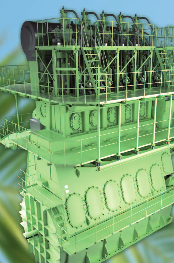
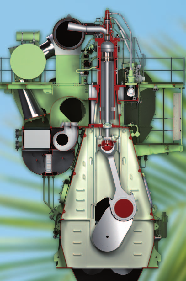
5 MAN B&W Low Speed Propulsion engines

6 6
7 MAN B&W Low Speed Propulsion Engines MAN Diesel & Turbo Tier II Engine Programme The engines in this programme all comply with IMO s Tier II emissions. ME Programme The electronic control of ME/ME-C/-GI engines includes the combustion process, i.e. fuel injection timing, actuation of exhaust valves and starting valves, and cylinder lubrication. On ME-B/-GI engines, the combustion process is electronically controlled while the actuation of exhaust valves and starting valves is hydraulically or mechanically controlled. The advantages of ME engines are: fuel optimised over a wide power range improved cylinder lube oil consumption improved low-load running adaptation to different fuel oil qualities better part- and low-load effiency As a standard integrated feature, ME engines are specified with MAN B&W Alpha Lubricators. GI Dual Fuel Engines In addition to the engines mentioned on page 55-66, the following are available for natural gas operation as dual fuel engines with high-pressure gas injection, designated -GI (Gas Injection): S65ME-C8.2 L60ME-C8.2 Currently, these engines have the same fuel consumption as diesel engines, but will be available with lower fuel consumption on request. ME-B engines (excl. S30ME-B9) are also available for natural gas operation. These engines have the same fuel consumption as similar diesel engines. Improved SFOC for Mark 9 Engines The test results from the first mark 9 engines have confirmed that the SFOC for large bore mark 9 engines has been improved compared to earlier versions. In addition, the S80ME-C9 has been upgraded mechanically to match the performance and SFOC of the S90ME-C9. 7
8 MAN B&W Low Speed Propulsion Engines MC Programme MAN B&W two-stroke MC/MC-C engines are characterised by having mechanically driven camshaft-controlled fuel pumps. VIT (Variable Injection Timing) fuel pumps are MAN Diesel & Turbo s standard design on mechanically controlled MC/MC-C Tier II engines with 46 bore and above. The engine s maximum firing pressure can be controlled accordingly to ensure optimum combination of NOx and SFOC can be obtained at all loads. Old Replaced Engines Earlier versions of this engine programme have additional engines mentioned. Those engine types are still available and are categorised Old replaced engines. However, new development will only be implemented in these designs to the extent considered necessary based on service experience. New efficiency enhancing features and SFOC guarantee down to 50% load will not be available on older engine types. Engine Power The engine brake power is stated in kw. The power values stated in the tables are available up to tropical conditions at sea level. i.e.: turbocharger compressor inlet temperature 45 C turbocharger compressor inlet pressure 1,000 mbar sea water temperature 32 C 8
9 MAN B&W Low Speed Propulsion Engines Specific Fuel Oil Consumption (SFOC) The figures given in this folder represent the values obtained when the engine and turbocharger are matched to the lowest possible SFOC values while also fulfilling the IMO NO x Tier II emission limitations. Stricter emission limits can be met on request, using proven technologies. The SFOC figures are given in g/kwh, and are based on the use of fuel with a lower calorific value (LCV) equal to 42,700 kj/kg (~10,200 kcal/kg) at ISO conditions: ambient air pressure 1,000 mbar ambient air temperature 25 C cooling water temperature 25 C Most commercially available HFO with a viscosity below 700 cst at 50 C can be used. The energy efficiency design index (EEDI) has increased the focus on partload SFOC. We therefore offer the option of selecting the SFOC guarantee at a load point in the range between 50% and 100%. All engine design criteria, e.g. heat load, bearing load and mechanical stresses on the construction are defined at 100% load independent of the guarantee point selected. This means that turbocharger matching, engine adjustment and engine load calibration must also be performed at 100% independent of guarantee point. At 100% load, the SFOC tolerance is 5%. When choosing an SFOC guarantee below 100%, the tolerances, which were previously compensated for by the matching, adjustment and calibration at 100%, will affect engine running at the lower SFOC guarantee load point. This includes tolerances on measurement equipment, engine process control and turbocharger performance. Consequently SFOC guarantee tolerances are as follows: 100% 85%: 5% tolerance 84% 65%: 6% tolerance 64% 50%: 7% tolerance Please note that the SFOC guarantee can only be given in one (1) load point. 9
10 MAN B&W Low Speed Propulsion Engines Layout Diagram The layout diagram applicable for the engines is defined by the power and speed combinations L 1 - L 2 - L 3 and L 4, with L 1 indicating the nominal MCR. Power L 1 L 3 L 2 Any combination of speed and power within the layout diagram may be used for selecting the specified MCR point. L 4 Speed G80ME-C9, G50ME-B9, G45ME-B9 and G40ME-B9 Engines Available at Increased Speed with Unchanged MEP Four of the G-engines (G80ME-C9, G50ME-B9, G45ME-B9 and G40ME-B9) are specified with the L 1 speed and power indicated in the table below: Engine L 1 speed [rpm] L 1 power/cyl. [kw] G80ME-C9 68 4,450 G50ME-B ,720 G45ME-B ,390 G40ME-B ,100 Variants of these engines with increased speed and unchanged MEP are available on request: Engine L 1 speed [rpm] L 1 power/cyl. [kw] G80ME-C9 72 4,710 G50ME-B ,860 G45ME-B ,505 G40ME-B ,190 Schematic Layout Diagram with Extended Area for G80ME-C9, G50ME-B9, G45ME-B9 and G40ME-B9 Power Speed 10
11 MAN B&W Low Speed Propulsion Engines Fuel Consumption and Optimisation Possibilities The current economic scenario has placed more emphasis on operational flexibility in terms of demand for improved part-load and low-load SFOC. As described below, different optimisation possibilities for the MAN B&W type engines have been developed. NOx regulations place a limit on the SFOC on two-stroke engines. In general, NOx emissions will increase if SFOC is decreased and vice versa. In the standard configuration, the engines are optimised close to the IMO NOx limit and, therefore, NOx emissions may not be further increased. The IMO NOx limit is given as a weighted average of the NOx emission at 25, 50, 75 and 100% load. This relationship can be utilised to tilt the SFOC profile over the load range. This means that SFOC can be reduced at part load or low load at the expense of a higher SFOC in the high-load range without exceeding the IMO NOx limit. Optimisation of SFOC in the part-load (50-85%) or low-load (25-70%) range requires selection of a tuning method: ECT: Engine Control Tuning (only available on ME/ME-C/ME-B engines) VT: Variable Turbine area EGB: Exhaust Gas Bypass The above tuning methods are available for all SMCR in the specific engine layout diagram. The specific SFOC reduction potential of each tuning method together with full rated (L 1 /L 3 ) and maximum derated (L 2 /L 4 ) can be seen for each individual engine page. Only high-load optimisation is available for engines with conventional efficiency turbochargers (64% instead of 67%) including S46ME-B8, S46MC-C8 and G45ME-B9 and for engines with non-adjustable maximum firing pressure at part load (MC engines without VIT). The methods and options mentioned will be explained in the following. For K98 engines high-load optimising is not a relevant option any more. However, for such engines in part-load or low-load optimised execution, the full 100% load is still available when needed for operational reasons. 11
12 MAN B&W Low Speed Propulsion Engines SFOC Curves for the GI Engines Examples of SFOC curves for GI engines with liquid fuel and gas fuel are shown on the following two graphs for L 1 and L 3 layout points respectively. Depending on engine type, these points differ. SFOC -6 g/kwh 35-4 g/kwh -1 g/kwh L1 Liquid fuel L1 Gas fuel Engine load 100 SFOC L3 Liquid fuel L3 Gas fuel -3.5 g/kwh -1 g/kwh g/kwh Engine load 100 SFOC Curves for the ME-B Engines The SFOC curves for the new ME-B engines with adjustable exhaust valve closing compared to the previous. SFOC -4.5 g/kwh Previous ME-B Updated ME-B -2.5 g/kwh 35 Engine load
13 MAN B&W Low Speed Propulsion Engines Engine Control Tuning Available for Bore Electronic Controlled Engines This method can be implemented without change of engine components (including matching of turbochargers), only engine control parameters are changed. The method solely utilises the possibility for variable exhaust valve timing and injection timing and profiling. Two different optimisation possibilities are available. With part-load optimisation, SFOC is decreased at all loads below 85%. With low-load optimisation, SFOC is further decreased at loads below 70%, however, at the expense of a higher SFOC in the high-load range. Which option is optimal on a specific engine depends on the operating pattern. Variable Turbine Area VT Technology (or similar) This method requires special turbocharger parts allowing the turbocharger(s) on the engine to vary the area of the nozzle ring. The nozzle ring area is minimum at the lower engine load range. When the engine load is increased above approx. 80%, the area gradually starts to increase and reaches its maximum at 90% engine load. With this technology, SFOC is decreased at low load at the expense of a higher SFOC at high load. The VT technology is available for both the ME and MC type engines. The SFOC potential is better on the ME type engine, where VT is combined with variable exhaust valve timing. For both the ME and MC type engines,two optimisation possibilities are available. With part-load optimisation, SFOC is decreased at all loads below 85%. With low-load optimisation, SFOC is further decreased at loads below 70%, at the expense of a higher SFOC in the high-load range. Which option is optimal on a specific engine depends on the operating pattern. 13
14 MAN B&W Low Speed Propulsion Engines Exhaust Gas Bypass (EGB) This method requires installation of EGB technology. The turbocharger(s) on the engine are matched at 100% load with fully open EGB. At approximately 85% load, the EGB starts to close and is fully closed below 70% load. With this technology SFOC is decreased at low load, at the expense of a higher SFOC at high load. The EGB technology is available for both ME and MC type engines. The SFOC potential is better on the ME type engine, where EGB is combined with variable exhaust valve timing. For both ME and MC type engines, two optimisation possibilities are available. With part-load optimisation, SFOC is decreased at all loads below 85%. With low-load optimisation, SFOC is further decreased at loads below 70%, at the expense of a higher SFOC in the high-load range. Which option is optimal depends on the operating pattern. Turbocharger (TC) Cut-out Besides the above-mentioned part-load and low-load methods (ECT, VT and EGB), cut-out of one turbocharger can be applied on MAN B&W engines with more than two turbochargers. The cut-out can be effected either by means of blind plates or pneumatically actuated valves. During cut-out, the allowed engine load is limited to 65% and 70% of SMCR for engines with 3 or 4 turbochargers, respectively. TC cut-out cannot be combined with other methods of low or part-load SFOC optimisations. The cut-out will enhance the performance of the working turbochargers and, thereby, lead to higher scavenge, compression and maximum combustion pressures, ultimately resulting in lower SFOC and lower exhaust gas temperatures and amount. Data for changes in SFOC, exhaust gas temperature and amount can be supplied on request for the actual project. Depending on the specific engine layout, the heat load can increase significantly when running close to the reduced limit for allowable engine load. 14
15 MAN B&W Low Speed Propulsion Engines Turbocharging System Two-stroke low speed engines can be delivered with MAN, ABB or MHI turbochargers as standard. The SFOC figures given in this folder for two-stroke engines are based on turbocharging with the best possible turbocharging efficiency generally available, i.e. 67% for all engines with 45 bore and above, and 64% for engine bores smaller than 45 cm. Both efficiency figures refer to 100% specified MCR. At lower loads the turbocharger efficiency will be even higher. All engines with high efficiency (67%) turbochargers can be ordered with lower turbocharging efficiency. Utilising this possibility will result in increased exhaust gas temperatures, reduced exhaust gas amounts, and a slight change in SFOC. Converting to conventional efficiency (64%), turbocharger(s) results in a small SFOC increase, a 20 C increase of the turbine outlet temperature, and a 6% decrease of the air/exhaust amount. It is not possible to apply tuning methods (part or low load) when making such a conversion. For more information visit: Products Marine Engines & Systems Low Speed Turbocharger Selection. 15
 and matching the engine for WHRS.")

16 MAN B&W Low Speed Propulsion Engines Waste Heat Recovery Systems Waste heat can be economically recovered from all MAN B&W two-stroke engines from 50 bore and up, by installing equipment for waste heat recovery systems (WHRS) and matching the engine for WHRS. A standard WHR-matched MAN B&W two-stroke engine will have a higher exhaust gas temperature compared with an engine without WHR, and can produce an extra electric power output corresponding to approx. 10% of the engine shaft power. Total system efficiency will therefore be better than that of the engine itself. Through state-of-the-art components offered by MAN Diesel & Turbo, up to 10% of otherwise lost main-engine power can be recovered. The electrical output varies from approximately 1-6 MW or higher, based on requirments. The Modular Arrangement Concept provides configuration flexibility with or without a power turbine. MAN Diesel & Turbo provides: complete WHRS WHRS integration/interfacing and performance guarantee WHRS comprising equipment from the most recognised and reliable suppliers available global service and after-sales network superior in-house technology concerning the interaction of complete WHRS with the main engine(s) the most effective EEDI reduction methods with a figure of up to 10% achievable 16
17 MAN B&W Low Speed Propulsion Engines Dual Steam Pressure and Heat Water Diagram Exhaust gas boiler sections: LP evaporator LP superheater LP steam drum LP LP circ. pump HP steam drum HP evaporator HP superheater HP HP circ. p. HP LP Exhaust gas PTO/ PTI TC Scavenge air cooler TC Exhaust gas receiver Main engine Jacket water Power turbine ST & PT unit Steam turbine Condenser Condensate Feedwater pump pump Hot well HP steam for heating services SFOC with different layout strategies SFOC STD WHR EGB-PL EGB-LL g/kwh WHR Total 35 Engine load
18 MAN B&W Low Speed Propulsion Engines Lubricating Oil Consumption The system oil consumption varies for the different engine sizes and operational patterns. Typical consumptions are in the range from negligible to 0.1 g/kwh. Specific Cylinder Oil Consumption Alpha ACC (Adaptive Cylinder-oil Control) is the lubrication mode for MAN B&W two-stroke engines, i.e. lube oil dosing proportional to the engine load and proportional to the sulphur content in the fuel oil being burnt. The specific minimum dosage at lower-sulphur fuels is set at 0.6 g/kwh. After a running-in period of 2,500 hours, the feed rate sulphur proportional factor is 0.20 g/kwh x S% for all engines with 60 bore and above and 0.26 g/kwh x S% for engines with 50 bore and below. Engines with 60 Bore and above ACC Dosage for BN70 Cylinder Oil Based on calculations of the Absolute dosage (g/kwh) 1.40 average worldwide sulphur content used on MAN B&W 1.10 two-stroke engines, the average cylinder oil consumption will be less than 0.65 g/kwh Engines with 50 Bore and below ACC Dosage for BN70 Cylinder Oil Based on calculations of the Absolute dosage (g/kwh) 1.40 average worldwide sulphur content used on MAN B&W 1.10 two-stroke engines, the average cylinder oil consumption will be less than 0.7 g/kwh Sulphur % Sulphur % Further information on cylinder oil as a function of fuel oil sulphur content and alkalinity of lubricating oil is available from MAN Diesel & Turbo. 18
19 MAN B&W Low Speed Propulsion Engines Extent of Delivery The final and binding extent of delivery of MAN B&W two-stroke engines is to be supplied by our licensee, the engine maker, who should be contacted in order to determine the execution for the actual project. In order to facilitate negotiations between the yard, the engine maker and the customer, a set of guiding Extent of Delivery (EoD) forms is available in which MAN Diesel & Turbo s recommended basic and optional executions are specified. Please note that licensees may select a different extent of delivery as their standard. CEAS - Engine Room Dimensioning The CEAS program calculates basic data essential for the design and dimensioning of a ship s engine room. CEAS is available at Products Marine Engines & Systems Low Speed CEAS Engine Room Dimensioning. In CEAS, engine designations have the version numbers.1,.2,.3 or.4. In this programme, K98ME7/ME-C7 refer to K98ME7.1 and K98ME-C7.1. The mechanically upgraded S80ME-C9 is named S80ME-C9.4. All other designations refer to.2, except ME-B engines, which refer to.3 e.g. G80ME-C9.2 and S50ME-B9.3. For the G80ME-C9, the CEAS calculations can be made for the extended layout area (ref. page 10), whereas for the G50ME-B9, G45ME-B9 and G40ME-B9, CEAS calculations for the extended layout area are available on request. Old replaced engines from earlier versions of the engine marine programme can now be found on CEAS with the following disclaimer: The following engines are all replaced by newer and more efficient engines. Data from the replaced engines should only be used for comparison and processing existing or repeat orders. For new projects the latest version of engine catalogue must be used. 19
20 MAN B&W Low Speed Propulsion Engines Engine Dimensions The minimum length L min is stated from the aft end of the crankshaft to the fore end of the engine. Bore: Bore: Bore: G-engines C C H 2 H 2 H 3 H 3 H 1 H 1 A L min A L min B B1 B2 L min : Minimum length of engine A: Cylinder distance B: Bedplate width B1: Bedplate width at foot flange B2: Bedplate width at top flange C: Crankshaft to underside of foot flange H 1 : Normal lifting procedure H 2 : Reduced height lifting procedure H 3 : With electric double-jib crane Dry Masses Dry masses are stated for engines with MAN turbocharger(s) and a standard turning wheel. The figures can vary up to 10% depending on the design and options chosen, e.g. moment compensators, tuning wheel, etc. Alternative Cylinder Numbers Engine types with 70 bore and smaller are available with 4 cylinders on request. 20
21 MAN B&W Low Speed Propulsion Engines Engine Type Designation 6 S 90 M E -C 9 -GI -TII Emission regulation TII IMO Tier level Fuel injection concept (blank)fuel oil only GI Gas injection Mark number Design Concept B C E C Exhaust valve controlled by camshaft Compact engine Electronically controlled Camshaft controlled Engine programme series Diameter of piston in cm Stroke/bore ratio Number of cylinders G S L K Green Ultra long stroke Super long stroke Long stroke Short stroke 21
22 MAN B&W K98ME-C7 Cyl. L1 kw Stroke: 2,400 mm 6 36, , , , , , , ,280 kw/cyl. L 1 L 3 6,020 5,620 4,830 4,510 L 2 L r/min SFOC for engines with layout on L 1 - L 3 line [g/kwh] L1/L3 MEP: 19.2 bar SFOC optimised load range Tuning 50% 75% 100% Part load (50%-85%) Low load (25%-70%) ECT EGB ECT EGB SFOC for engines with layout on L 2 - L 4 line [g/kwh] L2/L4 MEP: 15.4 bar SFOC optimised load range Tuning 50% 75% 100% Part load (50%-85%) Low load (25%-70%) ECT EGB ECT EGB Specifications Dimensions: A B C H1 H2 H3 mm 1,750 4,370 1,700 12,900 12,575 - Cylinders: L min mm 12,865 14,615 16,410 19,135 20,885 22,635 24,385 27,885 Dry mass t 1,046 1,211 1,393 1,532 1,680 1,912 1,975 2,246 22
23 MAN B&W K98ME7 Cyl. L1 kw Stroke: 2,660 mm 6 37, , , , , , , ,220 kw/cyl. L 1 L 3 6,230 5,780 5,000 4,630 L 2 L r/min SFOC for engines with layout on L 1 - L 3 line [g/kwh] L1/L3 MEP: 19.2 bar SFOC optimised load range Tuning 50% 75% 100% Part load (50%-85%) Low load (25%-70%) ECT EGB ECT EGB SFOC for engines with layout on L 2 - L 4 line [g/kwh] L2/L4 MEP: 15.4 bar SFOC optimis ed load range Tuning 50% 75% 100% Part load (50%-85%) Low load (25%-70%) ECT EGB ECT EGB Specifications Dimensions: A B C H1 H2 H3 mm 1,750 4,640 1,700 13,375 13,075 - Cylinders: L min mm 12,865 14,615 16,410 19,135 20,885 22,635 24,385 27,885 Dry mass t 1,067 1,220 1,437 1,581 1,755 1,895 2,058 2,328 23
24 MAN B&W S90ME-C9 Cyl. L1 kw Stroke: 3,260 mm 5 29, , , , , , , , ,340 kw/cyl. 5,250 L 3 4,200 L L 1 5,810 4,650 L 2 r/min SFOC for engines with layout on L 1 - L 3 line [g/kwh] L1/L3 MEP: 20.0 bar SFOC optimised load range Tuning 50% 75% 100% High load (85%-100%) ECT Part load (50%-85%) VT EGB ECT Low load (25%-70%) VT EGB SFOC for engines with layout on L 2 - L 4 line [g/kwh] L2/L4 MEP: 16.0 bar SFOC optimised load range Tuning 50% 75% 100% High load (85%-100%) ECT Part load (50%-85%) VT EGB ECT Low load (25%-70%) VT EGB Specifications Dimensions: A B C H1 H2 H3 mm 1,590 5,160 1,900 15,000 14,025 14,500 Cylinders: L min mm 11,212 12,802 13,585 16,115 17,705 19,295 20,885 22,475 25,765 Dry mass t 950 1,100 1,250 1,440 1,620 1,765 1,935 2,080 2,370 24
25 MAN B&W S90ME-C8 Cyl. L1 kw Stroke: 3,188 mm 6 31, , , ,430 kw/cyl. 4,870 L 3 3,890 L 4 L 1 5,270 4,220 L r/min SFOC for engines with layout on L 1 - L 3 line [g/kwh] L1/L3 MEP: 20.0 bar SFOC optimised load range Tuning 50% 75% 100% High load (85%-100%) ECT Part load (50%-85%) VT EGB ECT Low load (25%-70%) VT EGB SFOC for engines with layout on L 2 - L 4 line [g/kwh] L2/L4 MEP: 16.0 bar SFOC optimised load range Tuning 50% 75% 100% High load (85%-100%) ECT Part load (50%-85%) VT EGB ECT Low load (25%-70%) VT EGB Specifications Dimensions: A B C H1 H2 H3 mm 1,602 5,000 1,800 14,500 13,650 14,100 Cylinders: L min mm 12,802 14,404 16,006 17,608 Dry mass t 1,010 1,136 1,290 1,450 25
26 MAN B&W G80ME-C9 Cyl. L1 kw Stroke: 3,720 mm 6 26, , , ,050 kw/cyl. L 1 4,450 L 3 3,800 3,560 L 2 3,040 L r/min SFOC for engines with layout on L 1 - L 3 line [g/kwh] Specifications L1/L3 MEP: 21.0 bar SFOC optimised load range Tuning 50% 75% 100% High load (85%-100%) ECT Part load (50%-85%) VT EGB ECT Low load (25%-70%) VT EGB SFOC for engines with layout on L 2 - L 4 line [g/kwh] L2/L4 MEP: 16.8 bar SFOC optimised load range Tuning 50% 75% 100% High load (85%-100%) ECT Part load (50%-85%) VT EGB ECT Low load (25%-70%) VT EGB Dimensions: A B1 B2 C H1 H2 H3 mm 1,400 5,320 5,320 1,960 16,100 14,775 14,525 Cylinders: L min mm 10,735 12,135 13,535 14,935 Dry mass t 945 1,055 1,175 1,285 26
27 MAN B&W S80ME-C9 Cyl. L1 kw Stroke: 3,450 mm 6 27, , , ,590 kw/cyl. 4,160 L 3 3,330 L 4 L 1 4,510 3,610 L r/min SFOC for engines with layout on L 1 - L 3 line [g/kwh] L1/L3 MEP: 20.0 bar SFOC optimised load range Tuning 50% 75% 100% High load (85%-100%) ECT Part load (50%-85%) VT EGB ECT Low load (25%-70%) VT EGB SFOC for engines with layout on L 2 - L 4 line [g/kwh] L2/L4 MEP: 16.0 bar SFOC optimised load range Tuning 50% 75% 100% High load (85%-100%) ECT Part load (50%-85%) VT EGB ECT Low load (25%-70%) VT EGB Specifications Dimensions: A B C H1 H2 H3 mm 1,334 5,280 1,890 15,050 13,925 13,500 Cylinders: L min mm 10,100 11,434 12,768 14,102 Dry mass t ,043 1,153 27
28 MAN B&W S80ME-C8 Cyl. L1 kw Stroke: 3,200 mm 6 27, , ,000 kw/cyl. L 1 4,500 L 3 3,860 3,600 L 2 3,090 L r/min SFOC for engines with layout on L 1 - L 3 line [g/kwh] Specifications L1/L3 MEP: 20.0 bar SFOC optimised load range Tuning 50% 75% 100% High load (85%-100%) ECT Part load (50%-85%) VT EGB ECT Low load (25%-70%) VT EGB SFOC for engines with layout on L 2 - L 4 line [g/kwh] L2/L4 MEP: 16.0 bar SFOC optimised load range Tuning 50% 75% 100% High load (85%-100%) ECT Part load (50%-85%) VT EGB ECT Low load (25%-70%) VT EGB Dimensions: A B C H1 H2 H3 mm 1,424 5,000 1,736 14,325 13,175 12,950 Cylinders: L min mm 11,431 12,066 13,490 Dry mass t ,023 28
29 MAN B&W K80ME-C9 Cyl. L1 kw Stroke: 2,600 mm 6 27, , , , , , ,360 kw/cyl. 4,090 L 3 3,280 L L 1 4,530 3,620 L 2 r/min SFOC for engines with layout on L 1 - L 3 line [g/kwh] L1/L3 MEP: 20.0 bar SFOC optimised load range Tuning 50% 75% 100% High load (85%-100%) ECT Part load (50%-85%) VT EGB ECT Low load (25%-70%) VT EGB SFOC for engines with layout on L 2 - L 4 line [g/kwh] L2/L4 MEP: 16.0 bar SFOC optimised load range Tuning 50% 75% 100% High load (85%-100%) ECT Part load (50%-85%) VT EGB ECT Low load (25%-70%) VT EGB Specifications Dimensions: A B C H1 H2 H3 mm 1,334 4,400 1,650 12,400 11,825 11,675 Cylinders: L min mm 10,100 11,434 12,768 14,102 16,676 18,010 19,344 Dry mass t ,130 1,220 1,315 29
30 30
31 MAN B&W G70ME-C9 Cyl. L1 kw Stroke: 3,256 mm 5 18, , , ,120 kw/cyl. 2,890 L 3 L 1 3,640 2,910 L 2 2,310 L r/min SFOC for engines with layout on L 1 - L 3 line [g/kwh] L1/L3 MEP: 21.0 bar SFOC optimised load range Tuning 50% 75% 100% High load (85%-100%) ECT Part load (50%-85%) VT EGB ECT Low load (25%-70%) VT EGB SFOC for engines with layout on L 2 - L 4 line [g/kwh] L2/L4 MEP: 16.8 bar SFOC optimised load range Tuning 50% 75% 100% High load (85%-100%) ECT Part load (50%-85%) VT EGB ECT Low load (25%-70%) VT EGB Specifications Dimensions: A B1 B2 C H1 H2 H3 mm 1,260 4,760 4,900 1,750 14,925 * * Cylinders: L min mm 8,290 9,350 10,610 11,870 Dry mass t * Data is available on request 31
32 MAN B&W S70ME-C8 Cyl. L1 kw Stroke: 2,800 mm 5 16, , , ,160 kw/cyl. L 1 3,270 L 3 2,770 2,610 L 2 2,210 L r/min SFOC for engines with layout on L 1 - L 3 line [g/kwh] Specifications L1/L3 MEP: 20.0 bar SFOC optimised load range Tuning 50% 75% 100% High load (85%-100%) ECT Part load (50%-85%) VT EGB ECT Low load (25%-70%) VT EGB SFOC for engines with layout on L 2 - L 4 line [g/kwh] L2/L4 MEP: 16.0 bar SFOC optimised load range Tuning 50% 75% 100% High load (85%-100%) ECT Part load (50%-85%) VT EGB ECT Low load (25%-70%) VT EGB Dimensions: A B C H1 H2 H3 mm 1,190 4,390 1,520 12,550 11,675 11,475 Cylinders: L min mm 7,514 8,704 9,894 11,084 Dry mass t
33 MAN B&W L70ME-C8 Cyl. L1 kw Stroke: 2,360 mm 5 16, , , ,160 kw/cyl. L 1 3,270 L 3 2,750 2,620 L 2 2,200 L r/min SFOC for engines with layout on L 1 - L 3 line [g/kwh] Specifications L1/L3 MEP: 20.0 bar SFOC optimised load range Tuning 50% 75% 100% High load (85%-100%) ECT Part load (50%-85%) VT EGB ECT Low load (25%-70%) VT EGB SFOC for engines with layout on L 2 - L 4 line [g/kwh] L2/L4 MEP: 16.0 bar SFOC optimised load range Tuning 50% 75% 100% High load (85%-100%) ECT Part load (50%-85%) VT EGB ECT Low load (25%-70%) VT EGB Dimensions: A B C H1 H2 H3 mm 1,190 3,980 1,262 11,250 10,550 10,575 Cylinders: L min mm 7,639 8,829 10,019 11,209 Dry mass t
34 MAN B&W S65ME-C8 Cyl. L1 kw Stroke: 2,730 mm 5 14, , , ,960 kw/cyl. L 1 2,870 L 3 2,450 2,290 L 2 1,960 L r/min SFOC for engines with layout on L 1 - L 3 line [g/kwh] Specifications L1/L3 MEP: 20.0 bar SFOC optimised load range Tuning 50% 75% 100% High load (85%-100%) ECT Part load (50%-85%) VT EGB ECT Low load (25%-70%) VT EGB SFOC for engines with layout on L 2 - L 4 line [g/kwh] L2/L4 MEP: 16.0 bar SFOC optimised load range Tuning 50% 75% 100% High load (85%-100%) ECT Part load (50%-85%) VT EGB ECT Low load (25%-70%) VT EGB Dimensions: A B C H1 H2 H3 mm 1,084 4,124 1,410 11,950 11,225 11,025 Cylinders: L min mm 6,914 7,998 9,062 10,138 Dry mass t
35 MAN B&W G60ME-C9 Cyl. L1 kw Stroke: 2,790 mm 5 13, , , ,440 kw/cyl. 2,130 L 3 L 1 2,680 2,140 L 2 1,700 L r/min SFOC for engines with layout on L 1 - L 3 line [g/kwh] L1/L3 MEP: 21.0 bar SFOC optimised load range Tuning 50% 75% 100% High load (85%-100%) ECT Part load (50%-85%) VT EGB ECT Low load (25%-70%) VT EGB SFOC for engines with layout on L 2 - L 4 line [g/kwh] L2/L4 MEP: 16.8 bar SFOC optimised load range Tuning 50% 75% 100% High load (85%-100%) ECT Part load (50%-85%) VT EGB ECT Low load (25%-70%) VT EGB Specifications Dimensions: A B1 B2 C H1 H2 H3 mm 1,080 4,090 4,220 1,500 12,225 * * Cylinders: L min mm 8,000 8,280 9,360 10,440 Dry mass t * Data is available on request 35
36 MAN B&W S60ME-B8 Cyl. L1 kw Stroke: 2,400 mm 5 11, , , ,040 kw/cyl. L 1 2,380 L 3 2,010 1,900 L 2 1,610 L r/min SFOC for engines with layout on L 1 - L 3 line [g/kwh] L1/L3 MEP: 20.0 bar SFOC optimised load range Tuning 50% 75% 100% High load (85%-100%) ECT Part load (50%-85%) VT EGB ECT Low load (25%-70%) VT EGB SFOC for engines with layout on L 2 - L 4 line [g/kwh] L2/L4 MEP: 16.0 bar SFOC optimised load range Tuning 50% 75% 100% High load (85%-100%) ECT Part load (50%-85%) VT EGB ECT Low load (25%-70%) VT EGB The SFOC excludes 1 g/kwh for the consumption of the electric HPS Specifications Dimensions: A B C H1 H2 H3 mm 1,020 3,770 1,300 10,800 10,000 9,775 Cylinders: L min mm 7,122 8,142 9,162 10,182 Dry mass t Not yet available 36
37 MAN B&W S60ME-C8 Cyl. L1 kw Stroke: 2,400 mm 5 11, , , ,040 kw/cyl. L 1 2,380 L 3 2,010 1,900 L 2 1,610 L r/min SFOC for engines with layout on L 1 - L 3 line [g/kwh] Specifications L1/L3 MEP: 20.0 bar SFOC optimised load range Tuning 50% 75% 100% High load (85%-100%) ECT Part load (50%-85%) VT EGB ECT Low load (25%-70%) VT EGB SFOC for engines with layout on L 2 - L 4 line [g/kwh] L2/L4 MEP: 16.0 bar SFOC optimised load range Tuning 50% 75% 100% High load (85%-100%) ECT Part load (50%-85%) VT EGB ECT Low load (25%-70%) VT EGB Dimensions: A B C H1 H2 H3 mm 1,020 3,770 1,300 10,800 10,000 9,775 Cylinders: L min mm 6,439 7,459 8,479 9,499 Dry mass t
38 MAN B&W S60MC-C8 Cyl. L1 kw Stroke: 2,400 mm 5 11, , , ,040 kw/cyl. L 1 2,380 L 3 2,010 1,900 L 2 1,610 L r/min SFOC for engines with layout on L 1 - L 3 line [g/kwh] Specifications L1/L3 MEP: 20.0 bar SFOC optimised load range Tuning 50% 75% 100% High load (85%-100%) Part load (50%-85%) VT EGB Low load (25%-70%) VT EGB SFOC for engines with layout on L 2 - L 4 line [g/kwh] L2/L4 MEP: 16.0 bar SFOC optimised load range Tuning 50% 75% 100% High load (85%-100%) Part load (50%-85%) VT EGB Low load (25%-70%) VT EGB Dimensions: A B C H1 H2 H3 mm 1,020 3,770 1,300 10,775 10,025 9,775 Cylinders: L min mm 7,122 8,142 9,162 10,182 Dry mass t
39 MAN B&W L60ME-C8 Cyl. L1 kw Stroke: 2,022 mm 5 11, , , , ,060 kw/cyl. L 1 2,340 L 3 2,000 1,880 L 2 1,600 L r/min SFOC for engines with layout on L 1 - L 3 line [g/kwh] Specifications L1/L3 MEP: 20.0 bar SFOC optimised load range Tuning 50% 75% 100% High load (85%-100%) ECT Part load (50%-85%) VT EGB ECT Low load (25%-70%) VT EGB SFOC for engines with layout on L 2 - L 4 line [g/kwh] L2/L4 MEP: 16.0 bar SFOC optimised load range Tuning 50% 75% 100% High load (85%-100%) ECT Part load (50%-85%) VT EGB ECT Low load (25%-70%) VT EGB Dimensions: A B C H1 H2 H3 mm 1,020 3,490 1,134 9,650 9,125 8,925 Cylinders: L min mm 6,439 7,459 8,479 9,499 10,519 Dry mass t
40 40
41 MAN B&W G50ME-B9 Cyl. L1 kw Stroke: 2,500 mm 5 8, , , , ,480 kw/cyl. L 1 1,720 L 3 1,460 1,370 L 2 1,170 L r/min SFOC for engines with layout on L 1 - L 3 line [g/kwh] Specifications L1/L3 MEP: 21.0 bar SFOC optimised load range Tuning 50% 75% 100% High load (85%-100%) ECT Part load (50%-85%) VT EGB ECT Low load (25%-70%) VT EGB SFOC for engines with layout on L 2 - L 4 line [g/kwh] L2/L4 MEP: 16.8 bar SFOC optimised load range Tuning 50% 75% 100% High load (85%-100%) ECT Part load (50%-85%) VT EGB ECT Low load (25%-70%) VT EGB The SFOC excludes 1 g/kwh for the consumption of the electric HPS Dimensions: A B1 B2 C H1 H2 H3 mm 894 3,896 3,672 1,205 10,525 10,400 10,150 Cylinders: L min mm 6,325 7,200 8,075 8,950 9,825 Dry mass t
42 MAN B&W S50ME-B9 Cyl. L1 kw Stroke: 2,214 mm 5 8, , , , ,020 kw/cyl. L 1 1,780 L 3 1,510 1,420 L 2 1,210 L r/min SFOC for engines with layout on L 1 - L 3 line [g/kwh] L1/L3 MEP: 21.0 bar SFOC optimised load range Tuning 50% 75% 100% High load (85%-100%) ECT Part load (50%-85%) VT EGB ECT Low load (25%-70%) VT EGB SFOC for engines with layout on L 2 - L 4 line [g/kwh] L2/L4 MEP: 16.8 bar SFOC optimised load range Tuning 50% 75% 100% High load (85%-100%) ECT Part load (50%-85%) VT EGB ECT Low load (25%-70%) VT EGB The SFOC excludes 1 g/kwh for the consumption of the electric HPS Specifications Dimensions: A B C H1 H2 H3 mm 875 3,290 1,185 9,775 9,200 8,900 Cylinders: L min mm 6,073 6,948 7,823 8,698 9,573 Dry mass t
43 MAN B&W S50ME-B8 Cyl. L1 kw Stroke: 2,000 mm 5 8, , , , ,940 kw/cyl. L 1 1,660 L 3 1,410 1,330 L 2 1,130 L r/min SFOC for engines with layout on L 1 - L 3 line [g/kwh] L1/L3 MEP: 20.0 bar SFOC optimised load range Tuning 50% 75% 100% High load (85%-100%) ECT Part load (50%-85%) VT EGB ECT Low load (25%-70%) VT EGB SFOC for engines with layout on L 2 - L 4 line [g/kwh] L2/L4 MEP: 16.0 bar SFOC optimised load range Tuning 50% 75% 100% High load (85%-100%) ECT Part load (50%-85%) VT EGB ECT Low load (25%-70%) VT EGB The SFOC excludes 1 g/kwh for the consumption of the electric HPS Specifications Dimensions: A B C H1 H2 H3 mm 850 3,150 1,088 9,050 8,500 8,250 Cylinders: L min mm 5,924 6,774 7,624 8,474 9,324 Dry mass t
44 MAN B&W S50ME-C8 Cyl. L1 kw Stroke: 2,000 mm 5 8, , , , ,940 kw/cyl. L 1 1,660 L 3 1,410 1,330 L 2 1,130 L r/min SFOC for engines with layout on L 1 - L 3 line [g/kwh] Specifications L1/L3 MEP: 20.0 bar SFOC optimised load range Tuning 50% 75% 100% High load (85%-100%) ECT Part load (50%-85%) VT EGB ECT Low load (25%-70%) VT EGB SFOC for engines with layout on L 2 - L 4 line [g/kwh] L2/L4 MEP: 16.0 bar SFOC optimised load range Tuning 50% 75% 100% High load (85%-100%) ECT Part load (50%-85%) VT EGB ECT Low load (25%-70%) VT EGB Dimensions: A B C H1 H2 H3 mm 850 3,150 1,085 9,050 8,500 8,250 Cylinders: L min mm 5,924 6,774 7,624 8,474 9,324 Dry mass t
45 MAN B&W S50MC-C8 Cyl. L1 kw Stroke: 2,000 mm 5 8, , , , ,940 kw/cyl. L 1 1,660 L 3 1,410 1,330 L 2 1,130 L r/min SFOC for engines with layout on L 1 - L 3 line [g/kwh] Specifications L1/L3 MEP: 20.0 bar SFOC optimised load range Tuning 50% 75% 100% High load (85%-100%) Part load (50%-85%) VT EGB Low load (25%-70%) VT EGB SFOC for engines with layout on L 2 - L 4 line [g/kwh] L2/L4 MEP: 16.0 bar SFOC optimised load range Tuning 50% 75% 100% High load (85%-100%) Part load (50%-85%) VT EGB Low load (25%-70%) VT EGB Dimensions: A B C H1 H2 H3 mm 850 3,150 1,085 9,000 8,475 8,250 Cylinders: L min mm 5,924 6,774 7,624 8,474 9,324 Dry mass t
46 MAN B&W S46ME-B8 Cyl. L1 kw Stroke: 1,932 mm 5 6, , , ,040 kw/cyl. L 1 1,380 L 3 1,175 1,105 L L r/min SFOC for engines with layout on L 1 - L 3 line [g/kwh] L1/L3 MEP: 20.0 bar SFOC optimised load range Tuning 50% 75% 100% High load (85%-100%) SFOC for engines with layout on L 2 - L 4 line [g/kwh] L2/L4 MEP: 16.0 bar SFOC optimised load range Tuning 50% 75% 100% High load (85%-100%) The SFOC excludes 1 g/kwh for the consumption of the electric HPS Specifications Dimensions: A B C H1 H2 H3 mm 782 2, ,000 8,175 7,900 Cylinders: L min mm 5,528 6,310 7,092 7,874 Dry mass t
47 MAN B&W S46MC-C8 Cyl. L1 kw Stroke: 1,932 mm 5 6, , , ,040 kw/cyl. L 1 1,380 L 3 1,175 1,105 L L r/min SFOC for engines with layout on L 1 - L 3 line [g/kwh] L1/L3 MEP: 20.0 bar SFOC optimised load range Tuning 50% 75% 100% High load (85%-100%) SFOC for engines with layout on L 2 - L 4 line [g/kwh] L2/L4 MEP: 16.0 bar SFOC optimised load range Tuning 50% 75% 100% High load (85%-100%) Specifications Dimensions: A B C H1 H2 H3 mm 782 2, ,000 8,175 7,900 Cylinders: L min mm 5,528 6,310 7,092 7,874 Dry mass t
48 MAN B&W G45ME-B9 Cyl. L1 kw Stroke: 2,250 mm 5 6, , , ,120 kw/cyl. L 1 1,390 L 3 1,175 1,110 L L r/min SFOC for engines with layout on L 1 - L 3 line [g/kwh] L1/L3 MEP: 21.0 bar SFOC optimised load range Tuning 50% 75% 100% High load (85%-100%) SFOC for engines with layout on L 2 - L 4 line [g/kwh] L2/L4 MEP: 16.8 bar SFOC optimised load range Tuning 50% 75% 100% High load (85%-100%) The SFOC excludes 1 g/kwh for the consumption of the electric HPS Specifications Dimensions: A B1 B2 C H1 H2 H3 mm 826 3,506 3,306 1,085 9,900 * * Cylinders: L min mm 5,680 6,506 7,332 8,158 8,984 Dry mass t * Data is available on request 48
49 MAN B&W G40ME-B9 Cyl. L1 kw Stroke: 2,000 mm 5 5, , , ,800 kw/cyl. L 1 1,100 L L L r/min SFOC for engines with layout on L 1 - L 3 line [g/kwh] L1/L3 MEP: 21.0 bar SFOC optimised load range Tuning 50% 75% 100% High load (85%-100%) SFOC for engines with layout on L 2 - L 4 line [g/kwh] L2/L4 MEP: 16.8 bar SFOC optimised load range Tuning 50% 75% 100% High load (85%-100%) The SFOC excludes 1 g/kwh for the consumption of the electric HPS Specifications Dimensions: A B1 B2 C H1 H2 H3 mm 716 3,118 2, ,550 * * Cylinders: L min mm 5,060 5,775 6,490 7,205 7,920 Dry mass t * Data is available on request 49
50 MAN B&W S40ME-B9 Cyl. L1 kw Stroke: 1,770 mm 5 5, , , ,080 kw/cyl. L 1 1,135 L L L r/min SFOC for engines with layout on L 1 - L 3 line [g/kwh] L1/L3 MEP: 21.0 bar SFOC optimised load range Tuning 50% 75% 100% High load (85%-100%) SFOC for engines with layout on L 2 - L 4 line [g/kwh] L2/L4 MEP: 16.8 bar SFOC optimised load range Tuning 50% 75% 100% High load (85%-100%) The SFOC excludes 1 g/kwh for the consumption of the electric HPS Specifications Dimensions: A B C H1 H2 H3 mm 700 2, ,800 7,475 7,200 Cylinders: L min mm 5,000 5,700 6,400 7,100 Dry mass t
51 MAN B&W S40MC-C9 Cyl, L1 kw Stroke: 1,770 mm 5 5, , , ,080 kw/cyl. L 1 1,135 L L L r/min SFOC for engines with layout on L 1 - L 3 line [g/kwh] L1/L3 MEP: 21.0 bar SFOC optimised load range Tuning 50% 75% 100% High load (85%-100%) SFOC for engines with layout on L 2 - L 4 line [g/kwh] L2/L4 MEP: 16.8 bar SFOC optimised load range Tuning 50% 75% 100% High load (85%-100%) Specifications Dimensions: A B C H1 H2 H3 mm 700 2, ,800 7,475 7,200 Cylinders: L min mm 5,000 5,700 6,400 7,100 Dry mass t
52 MAN B&W S35ME-B9 Cyl. L1 kw Stroke: 1,550 mm 5 4, , , ,960 kw/cyl. L L L L r/min SFOC for engines with layout on L 1 - L 3 line [g/kwh] L1/L3 MEP: 21.0 bar SFOC optimised load range Tuning 50% 75% 100% High load (85%-100%) SFOC for engines with layout on L 2 - L 4 line [g/kwh] L2/L4 MEP: 16.8 bar SFOC optimised load range Tuning 50% 75% 100% High load (85%-100%) The SFOC excludes 1 g/kwh for the consumption of the electric HPS Specifications Dimensions: A B C H1 H2 H3 mm 612 2, ,875 6,700 6,325 Cylinders: L min mm 4,378 4,990 5,602 6,214 Dry mass t
53 MAN B&W S35MC-C9 Cyl. L1 kw Stroke: 1,550 mm 5 4, , , ,960 kw/cyl. L L L L r/min SFOC for engines with layout on L 1 - L 3 line [g/kwh] L1/L3 MEP: 21.0 bar SFOC optimised load range Tuning 50% 75% 100% High load (85%-100%) SFOC for engines with layout on L 2 - L 4 line [g/kwh] L2/L4 MEP: 16.8 bar SFOC optimised load range Tuning 50% 75% 100% High load (85%-100%) Specifications Dimensions: A B C H1 H2 H3 mm 612 2, ,875 6,700 6,325 Cylinders: L min mm 4,378 4,990 5,602 6,214 Dry mass t
54 MAN B&W S30ME-B9 Cyl. L1 kw Stroke: 1,328 mm 5 3, , , ,120 kw/cyl. L L L L r/min SFOC for engines with layout on L 1 - L 3 line [g/kwh] L1/L3 MEP: 21.0 bar SFOC optimised load range Tuning 50% 75% 100% High load (85%-100%) SFOC for engines with layout on L 2 - L 4 line [g/kwh] L2/L4 MEP: 16.8 bar SFOC optimised load range Tuning 50% 75% 100% High load (85%-100%) The SFOC excludes 1 g/kwh for the consumption of the electric HPS Specifications Dimensions: A B C H1 H2 H3 mm 525 1, ,000 * * Cylinders: L min mm 3,765 4,290 4,815 5,340 Dry mass t * Data is available on request 54

55 MAN B&W Low Speed GI Dual Fuel Engines 55
56 MAN B&W S90ME-C9-GI Cyl. L1 kw Stroke: 3,260 mm 5 29, , , , , , , , ,340 kw/cyl. 5,250 L 3 4,200 L L 1 5,810 4,650 L 2 r/min SFOC gas engines [g/kwh] Gas fuel Liquid fuel Specifications Dimensions: A B C H1 H2 H3 mm 1,590 5,140 1,900 15,000 14,025 14,500 L1/L3 MEP: 20.0 bar L2/L4 MEP: 16.0 bar 50% 75% 100% L L L L L 1/ L L 2/ L Specific gas consumption consists of 5% pilot liquid fuel and gas fuel. Gas fuel LCV (50000 kj/kg) is converted to diesel fuel LCV (42,700 kj/kg) for comparison. Cylinders: L min mm 10,715 12,305 13,895 15,485 18,885 20,855 22,445 24,225 27,595 Dry mass t 950 1,100 1,250 1,440 1,620 1,765 1,935 2,080 2,370 56
57 MAN B&W S90ME-C8-GI Cyl. L1 kw Stroke: 3,188 mm 6 31, , , ,430 kw/cyl. 4,870 L 3 3,890 L 4 L 1 5,270 4,220 L r/min SFOC gas engines [g/kwh] Gas fuel Liquid fuel Specifications L1/L3 MEP: 20.0 bar L2/L4 MEP: 16.0 bar 50% 75% 100% L L L L L 1/ L L 2/ L Specific gas consumption consists of 5% pilot liquid fuel and gas fuel. Gas fuel LCV (50000 kj/kg) is converted to diesel fuel LCV (42,700 kj/kg) for comparison. Dimensions: A B C H1 H2 H3 mm 1,602 5,000 1,800 14,500 13,650 14,100 Cylinders: L min mm 12,802 14,404 16,006 17,608 Dry mass t 1,010 1,136 1,290 1,450 57
58 MAN B&W G80ME-C9-GI Cyl. L1 kw Stroke: 3,720 mm 6 26, , , ,050 kw/cyl. L 1 4,450 L 3 3,800 3,560 L 2 3,040 L r/min SFOC gas engines [g/kwh] Gas fuel Liquid fuel Specifications L1/L3 MEP: 21.0 bar L2/L4 MEP: 16.8 bar 50% 75% 100% L L L L L 1/ L L 2/ L Specific gas consumption consists of 5% pilot liquid fuel and gas fuel. Gas fuel LCV (50000 kj/kg) is converted to diesel fuel LCV (42,700 kj/kg) for comparison. Dimensions: A B1 B2 C H1 H2 H3 mm 1,400 5,180 5,360 1,960 16,100 14,775 14,525 Cylinders: L min mm 10,735 12,135 13,535 14,935 Dry mass t 945 1,055 1,175 1,285 58
59 MAN B&W S80ME-C9-GI Cyl. L1 kw Stroke: 3,450 mm 6 27, , , ,590 kw/cyl. L 3 4,160 3,330 L 4 L 1 4,510 3,610 L r/min SFOC gas engines [g/kwh] Gas fuel Liquid fuel L1/L3 MEP: 20.0 bar L2/L4 MEP: 16.0 bar 50% 75% 100% L L L L L 1/ L L 2/ L Specific gas consumption consist of 5% pilot liquid fuel and gas fuel Gas fuel LCV (50,000 kj/kg) is converted to diesel fuel LCV (42,700 kj/kg) for comparison Specifications Dimensions: A B C H1 H2 H3 mm 1,334 5,280 1,900 15,050 13,925 13,500 Cylinders: L min mm 10,100 11,434 12,768 14,102 Dry mass t ,020 1,130 59
60 MAN B&W S80ME-C8-GI Cyl. L1 kw Stroke: 3,200 mm 6 27, , ,000 kw/cyl. L 1 4,500 L 3 3,860 3,600 L 2 3,090 L r/min SFOC gas engines [g/kwh] Gas fuel Liquid fuel L1/L3 MEP: 20.0 bar L2/L4 MEP: 16.0 bar 50% 75% 100% L L L L L 1/ L L 2/ L Specific gas consumption consist of 5% pilot liquid fuel and gas fuel Gas fuel LCV (50,000 kj/kg) is converted to diesel fuel LCV (42,700 kj/kg) for comparison Specifications Dimensions: A B C H1 H2 H3 mm 1,424 5,000 1,736 14,325 13,175 12,950 Cylinders: L min mm 11,431 12,855 14,279 Dry mass t ,023 60
61 MAN B&W G70ME-C9-GI Cyl. L1 kw Stroke: 3,256 mm 5 18, , , ,120 kw/cyl. 2,890 L 3 L 1 3,640 2,910 L 2 2,310 L r/min SFOC gas engines [g/kwh] L1/L3 MEP: 21.0 bar L2/L4 MEP: 16.8 bar 50% 75% 100% L L Gas fuel L L L 1/ L Liquid fuel L 2/ L Specific gas consumption consist of 5% pilot liquid fuel and gas fuel Gas fuel LCV (50,000 kj/kg) is converted to diesel fuel LCV (42,700 kj/kg) for comparison Specifications Dimensions: A B1 B2 C H1 H2 H3 mm 1,260 4,760 4,900 1,750 14,925 * * Cylinders: L min mm 8,335 9,595 10,855 12,115 Dry mass t * Data is available on request 61
62 MAN B&W S70ME-C8-GI Cyl. L1 kw Stroke: 2,800 mm 5 16, , , ,160 kw/cyl. L 1 3,270 L 3 2,770 2,610 L 2 2,210 L r/min SFOC gas engines [g/kwh] L1/L3 MEP: 20.0 bar L2/L4 MEP: 16.0 bar 50% 75% 100% L L Gas fuel L L L 1/ L Liquid fuel L 2/ L Specific gas consumption consist of 5% pilot liquid fuel and gas fuel Gas fuel LCV (50,000 kj/kg) is converted to diesel fuel LCV (42,700 kj/kg) for comparison Specifications Dimensions: A B C H1 H2 H3 mm 1,190 4,390 1,520 12,550 11,675 11,475 Cylinders: L min mm 8,308 9,498 10,688 11,878 Dry mass t
63 MAN B&W L70ME-C8-GI Cyl. L1 kw Stroke: 2,360 mm 5 16, ,620 kw/cyl. L ,890 3,270 L ,160 2,750 2,620 L 2 2,200 L r/min SFOC gas engines [g/kwh] Gas fuel Liquid fuel L1/L3 MEP: 20.0 bar L2/L4 MEP: 16.0 bar 50% 75% 100% L L L L L 1/ L L 2/ L Specific gas consumption consist of 5% pilot liquid fuel and gas fuel Gas fuel LCV (50,000 kj/kg) is converted to diesel fuel LCV (42,700 kj/kg) for comparison Specifications Dimensions: A B C H1 H2 H3 mm 1,190 3,980 1,262 11,250 10,550 10,575 Cylinders: L min mm 7,639 8,829 10,019 11,209 Dry mass t
64 MAN B&W G60ME-C9-GI Cyl. L1 kw Stroke: 2,790 mm 5 13, , , ,440 kw/cyl. 2,130 L 3 L 1 2,680 2,140 L 2 1,700 L r/min SFOC gas engines [g/kwh] L1/L3 MEP: 21.0 bar L2/L4 MEP: 16.8 bar 50% 75% 100% L L Gas fuel L L L 1/ L Liquid fuel L 2/ L Specific gas consumption consist of 5% pilot liquid fuel and gas fuel Gas fuel LCV (50,000 kj/kg) is converted to diesel fuel LCV (42,700 kj/kg) for comparison Specifications Dimensions: A B1 B2 C H1 H2 H3 mm 1,080 4,090 4,220 1,500 12,225 * * Cylinders: L min mm 7,150 8,230 9,310 10,390 Dry mass t * Data is available on request 64
65 MAN B&W S60ME-C8-GI Cyl. L1 kw Stroke: 2,400 mm 5 11, , , ,040 kw/cyl. L 1 2,380 L 3 2,010 1,900 L 2 1,610 L r/min SFOC gas engines [g/kwh] L1/L3 MEP: 20.0 bar L2/L4 MEP: 16.0 bar 50% 75% 100% L L Gas fuel L L L 1/ L Liquid fuel L 2/ L Specific gas consumption consist of 5% pilot liquid fuel and gas fuel Gas fuel LCV (50,000 kj/kg) is converted to diesel fuel LCV (42,700 kj/kg) for comparison Specifications Dimensions: A B C H1 H2 H3 mm 1,020 3,770 1,300 10,800 10,000 9,775 Cylinders: L min mm 7,122 8,142 9,162 10,182 Dry mass t
66 MAN B&W S50ME-C8-GI Cyl. L1 kw Stroke: 2,000 mm 5 8, , , , ,940 kw/cyl. L 1 1,660 L 3 1,410 1,330 L 2 1,130 L r/min SFOC gas engines [g/kwh] L1/L3 MEP: 20.0 bar L2/L4 MEP: 16.0 bar 50% 75% 100% L 1 164,5 162,0 169,0 L 2 160,5 156,0 163,0 Gas fuel L 3 165,0 163,5 169,0 L 4 161,0 157,5 163,0 L 1/ L 3 168,5 166,0 170,0 Liquid fuel L 2/ L 4 164,5 160,0 164,0 Specific gas consumption consist of 5% pilot liquid fuel and gas fuel Gas fuel LCV (50,000 kj/kg) is converted to diesel fuel LCV (42,700 kj/kg) for comparison Specifications Dimensions: A B C H1 H2 H3 mm 850 3,150 1,085 9,050 8,500 8,250 Cylinders: L min mm 5,924 6,774 7,624 8,474 9,324 Dry mass t

67 MAN B&W Low Speed Propulsion systems
68 Fixed Pitch Propeller Programme The MAN Alpha FPP portfolio covers: power range of 4-40 MW per shaft blade configurations for 3, 4, 5 and 6-bladed propellers propellers with integrated shaft line and stern tube solutions a wide range of stern tube lube and sealing systems oil, water, biodegradable oils The MAN Alpha FPP's are characterised by the following benefits: high-efficient hydrodynamically optimised blade profiles Kappel designs available high reliability: Robust approach with ample mechanical design margins high-efficient aft ship integration with rudder, rudder bulb, ducts, etc. layouts for complete two-stroke propulsion systems, e.g. with PTO solutions plant calculations with upfront consideration to TVC, alignment and control systems 68

69 MAN B&W Low Speed Propulsion Systems MAN Alpha Controllable Pitch Propeller as standard Mk 5 versions are 4-bladed and 5-bladed versions are available upon request the figures stated after VBS indicate the propeller hub diameter standard blade/hub materials are Ni-Al-bronze, stainless steel is optional the propellers are available up to the highest ice classes. The below standard programmes, however, are based on no ice. VBS Mk 5 CP Propeller Programme 11,000 10,000 9,000 8,000 Propeller diameter (mm) 7,000 6,000 5,000 4,000 3,000 2,000 1,000 VBS790 VBS720 VBS660 VBS600 VBS860 VBS940 VBS1020 VBS1100 VBS1180 VBS1260 VBS1350 VBS1450 VBS1550 VBS1640 VBS1730 VBS1810 VBS1890 VBS1970 VBS2060 VBS2150 Hub sizes: Small: VBS Medium: VBS Large: VBS ,000 10,000 15,000 20,000 25,000 30,000 35,000 40,000 45,000 50,000 55,000 Engine Power [kw] 69
70 MAN B&W Standard Package Examples Cyl. kw Prop. speed r/min D 1) mm Hub VBS mm Q mm R mm W min mm Prop. mass t 2) G70ME-C9/-GI 3) 5 18, ,100 1,890 1,436 1,496 3, , ,450 2,060 1,565 1,593 3, , ,750 2,150 1,634 1,645 3, , ) S70ME-C8/-GI 3) 5 16, ,450 1,810 1,375 1,413 3, , ,750 1,890 1,436 1,500 3, , ,050 1,970 1,497 1,550 3, , ,250 2,060 1,565 1,630 3, L70ME-C8/-GI 3) 5 16, ,750 1,640 1,246 1,306 3, , ,000 1,730 1,315 1,367 3, , ,250 1,810 1,375 1,448 3, , ,400 1,890 1,436 1,500 3, S65ME-C8/-GI 3) 5 14, ,150 1,730 1,315 1,339 3,400 66,1 6 17, ,450 1,810 1,375 1,385 3,400 73,0 7 20, ,700 1,890 1,436 1,466 3,400 81,2 8 22, ,900 1,970 1,497 1,512 3,400 89,3 1) For optimal Kappel blades, the propeller diameter is reduced by an average of 3-10% compared to the listed standard diameters 2) The masses are stated for 3,000 mm stern tube and 6,000 mm propeller shaft 3) The masses are stated for 4,000 mm stern tube and 8,000 mm propeller shaft 5) Available on request D 70 Q R S~3000 W min
71 Cyl. kw Prop. speed r/min MAN B&W Standard Package Examples D 1) mm Hub VBS mm Q mm R mm W min mm Prop. mass t 2) G60ME-C9/-GI 3) 5 13, ,950 1,640 1,246 1,287 3, , ,250 1,730 1,315 1,339 3, , ,450 1,810 1,375 1,420 3, , ,700 1,890 1,436 1,496 3, S60MC-C/ME-B8, S60ME-C8/-GI 5 11, ,500 1,550 1,278 1,289 3, , ,750 1,640 1,367 1,362 3, , ,950 1,730 1,367 1,367 3, , ,150 1,810 1,458 1,450 3, L60MC-C/ME-B8, L60ME-C8/-GI 4) 5 11, ,900 1,450 1,175 1,248 2, , ,100 1,550 1,278 1,284 2, , ,300 1,640 1,278 1,284 2, , ,450 1,640 1,367 1,367 2, G50ME-B9 3) 5 8, ,150 1,450 1,102 1,174 3, , ,450 1,550 1,178 1,231 3, , ,650 1,550 1,178 1,231 3, , ,850 1,640 1,246 1,287 2, , ,050 1,730 1,315 1,339 3, S50ME-B9 5 8, ,650 1,460 1,100 1,141 2, , ,850 1,560 1,175 1,202 2, , ,050 1,560 1,175 1,202 2, , ,200 1,680 1,278 1,279 2, , ,350 1,800 1,367 1,332 2, S50MC-C/ME-B8, S50ME-C8/-GI 4) 5 8, ,400 1,350 1,030 1,082 2, , ,600 1,350 1,100 1,145 2, , ,800 1,450 1,175 1,233 2, , ,950 1,450 1,175 1,248 2, ) For optimal Kappel blades, the propeller diameter is reduced by an average of 3-10% compared to the listed standard diameters 2) The masses are stated for 3,000 mm stern tube and 6,000 mm propeller shaft 3) The masses are stated for 4,000 mm stern tube and 8,000 mm propeller shaft 4) Data for 9 cylinders is available on request 71
72 Cyl. kw Prop. speed r/min D 1) mm Hub VBS mm Q mm R mm W min mm Prop. mass t 2) S46MC-C/ME-B8 5 6, ,200 1, ,035 2, , ,400 1,350 1,030 1,082 2, , ,550 1,350 1,100 1,145 2, , ,700 1,450 1,175 1,233 2, G45ME-B9 5 6, ,650 1, , ,900 1, , ,100 1, , ,250 1,550 G40ME-B9 3) , , , ,9 S40MC-C/ME-B9 5 5, ,650 1, , , ,800 1, ,025 2, , ,950 1, ,025 2, , ,050 1,260 1,030 1,081 2, S35MC-C/ME-B9 5 4, , , , ,200 1, , , ,350 1, , , ,450 1, , S30ME-B9 3) , , , ,0 1) For optimal Kappel blades, the propeller diameter is reduced by an average of 3-10% compared to the listed standard diameters 2) The masses are stated for 3,000 mm stern tube and 6,000 mm propeller shaft 3) The masses are stated for 3,000 mm stern tube and 8,000 mm propeller shaft 4) Data for 9 cylinders is available on request 72

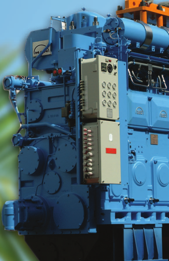
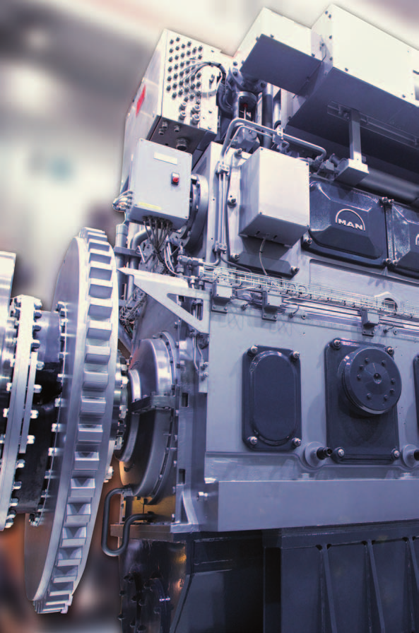
73 MAN Medium Speed Propulsion engines
74 74
75 MAN Medium Speed Propulsion Engines IMO Tier II Compliant Engine Programme Besides the focus on power density and fuel economy, MAN Diesel & Turbo has also committed itself to a steady reduction of the environmental impact of its engines. By applying engine internal and well-proven measures to achieve a cleaner and more efficient combustion, MAN Diesel & Turbo is able to decrease NO x emissions to IMO Tier II level without applying exhaust gas aftertreatment. 75

76 MAN Medium Speed Propulsion Engines MAN Diesel & Turbo SCR system The MAN Diesel & Turbo SCR system uses urea to transform the pollutant NO x into nitrogen and water vapour. This system has been specially adapted to our engines, and the control unit has been integrated into our engine control program SaCoSone. Under the right preconditions, SCR is capable of complying with IMO Tier III regulations. The MAN Diesel & Turbo SCR system standard is available in fifteen different sizes to cover the complete engine portfolio. Furthermore, customised SCR systems can be offered on demand. The two main components of an SCR system are the reactor, containing a number of catalyst cores, and the urea supply system, comprising a pump station dosing unit and a control unit. As an option, a NO x measuring system can be included to achieve a closed loop control of the urea injection. 76
77 MAN Medium Speed Propulsion Engines B A H MAN Diesel & Turbo SCR System Dimension Table Engine Group Engine Power [kw] Width A [mm] Reactor Dimension Length B [mm] Height H [mm] Total Reactor Weight [kg] Mixing Pipe Length [mm] , , ,650 1,050 1,050 2, , ,651 2,025 1,350 1,150 2,500 1,100 2, ,026 3,000 1,550 1,320 2,800 1,400 3, ,001 3,500 1,700 1,460 2,900 1,800 3, ,501 4,000 1,650 1,650 2,900 1,900 3, ,001 5,040 1,980 1,630 3,000 2,100 3, ,041 6,720 1,990 2,250 3,400 3,000 3, ,721 8,000 2,300 2,250 3,600 3,800 4, ,001 9,000 2,650 2,250 3,800 3,900 4, ,001 10,080 2,650 2,420 3,900 3,950 4, ,081 12,600 2,950 2,950 4,300 5,500 4, ,601 14,400 3,250 2,950 4,500 7,500 4, ,401 16,800 3,250 3,250 4,500 8,500 5, ,801 21,600 3,600 3,900 5,500 12,500 5,400 77

78 MAN Medium Speed Propulsion Engines MAN Diesel & Turbo Dry Exhaust Gas Cleaning System (DryEGCS ) The DryEGCS system enables the vessel to comply with IMO's sulphur regulations inside emission control areas while still operating the engines on HFO with up to 4.5% sulphur content. This enables the operator to achieve significant cost savings compared with an otherwise needed fuel switch to expensive distillate fuels. The DryEGCS is based on absorption of SO x in the reactor by using hydrated lime granulate. The main component of the system is the reactor, which contains the packed bed granulate. The exhaust gas passes through the granules and the SO x reacts with the slacked lime to gypsum, thus removing it completely from the biosphere. The DryEGCS standard is available in different sizes to cover the complete MAN engine portfolio. Customising the DryEGCS system for special purposes is easy. 78
79 MAN Medium Speed Propulsion Engines H B A MAN Diesel & Turbo DryEGCS Dimension Table Category Engine Power [kw] Design Width A [mm] Length B [mm] Height H [mm] Total Absorber weight [t] I 450 2,380 Transversal = Longitudinal 2,440 3,300 6,350 9, II 2,381 6,720 Transversal* 4,680 3,300 7,850 11, Longitudinal 3,840 5,600 7,850 11, III 6,721 10,080 Transversal* 6,920 3,300 9,850 11, Longitudinal 3,840 8,300 9,850 11, IV 10,081 12,000 Transversal* 6,920 3,700 11,850 13, Longitudinal 4,240 8,900 11,850 13, V 12,001 21,600 Transversal* 10,280 3,700 11,350 14, Longitudinal 5,360 8,900 11,350 14, * Default design 79
80 MAN Medium Speed Propulsion Engines Conventional Injection Engines These well-established engine types are used in various applications all around the world. Based on long-term experience, the engines have been continously developed to improve their power, emissions, fuel oil consumption and reliability, making them the prime mover of choice in the maritime sector. Common Rail (CR) Engines The flexibility of the CR technology offers benefits in the combustion process and in the fuel economy, while still keeping the IMO Tier II emission levels. This gives unique advantages, especially in the low-load range where the exhaust gas opacity can be brought down far below the visible limit. CR engines from MAN Diesel & Turbo run efficiently on liquid fuels complying with ISO DMA, DMZ, and DMB, and on residual fuels up to 700 cst (in compliance with ISO-F-RMK 700). Diesel Oil (D) Engines The V28/33D features very favourable ratios of power-to-weight and power-to-installation space. Its combination of low fuel consumption, low emissions and reduced life cycle costs makes this engine the ideal solution for propulsion in high speed ferries, naval and offshore patrol vessels. The V28/33D engine operates on distillates according to ISO 8217 DMA or equivalent fuel types. 80
81 MAN Medium Speed Propulsion Engines Sequential Turbocharging (STC) The MAN Diesel & Turbo sequential turbocharging system operates with two high-efficiency turbochargers. Depending on the amount of charge air required, the second turbocharger is switched on or off. In this way, the engine is operated at its optimum operating point over the whole applicable load range. The result is an extended operating envelope at low engine speeds, which gives a power reserve for ship acceleration, ship turning, sprints or towing. Furthermore, the STC-system is characterised by a low thermal signature, decreased smoke emission, low vibrations and continuous low-load operation with reduced fuel consumption, which makes it the ideal solution for propulsion in naval applications and offshore patrol vessels. Dual Fuel (DF) Engines Dual fuel engines from MAN Diesel & Turbo run efficiently on liquid fuels or natural gas with emissions far below the IMO limit. The possibility to switch over seamlessly from gas to diesel operation and vice versa provides full flexibility in multiple applications. All dual fuel engines can run on natural gas with a methane number higher than 80 without adjustments. For lower methane numbers, MAN Diesel & Turbo can deliver well-adapted solutions. The optimised combustion chamber ensures very low fuel consumption in both operational modes. 81
82 MAN Medium Speed Propulsion Engines Diesel-Electric and Hybrid Propulsion Trains Apart from the well-established diesel-mechanic propulsion packages, based on the MAN Alpha propeller programme (see pages ), MAN Diesel & Turbo offers a full range of diesel-electric and hybrid propulsion trains. The solutions offered are designed and optimised to meet the highest efficiencies of the complete propulsion plant system over the whole operational profile of the vessel. The systems provide well-balanced and tailor-made solutions regarding flexibility and performance. The propulsion packages include all components from gensets to propulsors, including switchboards, variable speed drives, and propulsion motors. Full diesel-electric propulsion trains as well as hybrid systems for CoDLaD and CoDLoD applications ensure the optimal technical and economical solution for flexible power demands. High-efficient and customised power trains for diesel-electric and hybrid propulsion applications 82
83 MAN Medium Speed Propulsion Engines Energy-Saving Electric Propulsion Recent developments in the electric component technology have paved the way for diesel-electric propulsion systems with a high potential in energy saving. Diesel engines now can operate at variable speeds, which means that the rpm of the engines can be adjusted for minimum fuel oil consumption according to the system load. Based on a common DC-distribution inside the system, power generation and consumption is decoupled. Diesel & Turbo offers this advanced package solutions in cooperation with leading E-suppliers. Another major advantage is the integration of energy storage sources, like batteries. The energy storage sources reduce the transient loads on the diesel engines and give much better system dynamic response times. Also, emission-free propulsion can be realized when running on batteries. The footprint of such a propulsion plant is up to 30% less compared with a classic diesel-electric propulsion plant. DC AC AC Energy-saving diesel-electric propulsion plant 83
84 MAN Medium Speed Propulsion Engines Engine Power Engine brake power is stated in kw. Ratings are given according to ISO :2002. According to ISO 15550:2002, the power figures in the tables remain valid within a range of ±3% up to tropical conditions at sea level, i.e.: compressor inlet temperature 45 C compressor inlet pressure 1,000 mbar sea water temperature 32 C For all medium speed propulsion engines, except for V28/33D and V28/33D STC, the power is defined according to the ICN 1 definition (ISO :2002 : ISO standard power). The engine rated power for V28/33D and V28/33D STC refers to ICFN 1 power definition (ISO 3046:2002 : ISO standard fuel stop power). Furthermore, two different load profile types are considered for V28/33D and V28/33D STC depending on the engine application. Load profile type: Navy Load profile type: Ferry Time [%] Time [%] Load: 0% to 10% 10% to 70% 70% to 100% 0 Load: 0% to 10% 10% to 88% 88% to 100% Typical use : Fast yachts Corvettes Frigates OPV Typical use : Ferries Catamarans Commercial vessels 1 IC[F]N according ISO :2002 : I = ISO power C = continuous power output [F = fuel stop power] N = net 84
85 MAN Medium Speed Propulsion Engines Specific Fuel Oil Consumption (SFOC) and Heat Rate The stated consumption figures refer to the following reference conditions according to ISO : ambient air pressure 1,000 mbar ambient air temperature 25 C (77 F) charge air temperature according to engine type, corresponding to 25 C cooling water temperature before CAC The figures are given with a tolerance of +5% and without engine driven pumps. Attached pumps and engines running in suction dredger operation will require additional fuel. The SFOC figures for engines in diesel operation are based on a lower calorific value of the fuel of 42,700 kj/kg. Specific Lube Oil Consumption (SLOC) The specific lube oil consumption is specified at MCR (maximum continuous rating) with a tolerance of 20%. Blocking of Output Blocking of output is made for engines driving a propeller at 100% of the rated output. For engines powering an alternator, blocking of output is made at 110%. However, operation above 100% load is only recommended for a short period of time for recovery and prevention of a frequency drop. Weights and Dimensions For marine main engines, the weights stated refer to engines without a flywheel. For auxiliary engines (GenSets), the weights correspond to the unit (including alternator). The weight of the GenSets may vary depending on the alternator make. All weights given are without lube oil and cooling water. The length of the GenSet unit depends on the alternator make. For a twin engine installation, the centreline distance is stated for each engine type. 85
86 MAN Medium Speed Propulsion Engines Engine Type Designation 12V28/33D STC Appendix technical key feature (e.g. CR, STC, TS) Appendix fuel for others than HFO (e.g. DF, D, G) Stroke in cm Bore in cm L or V version Number of cylinders 86
87 MAN Medium Speed Propulsion Engines r/min L51/60DF V51/60DF L48/60CR V48/60CR L48/60B V48/60B L35/44DF L32/44CR V32/44CR L32/40 V32/ V28/33D* V28/33D STC* 775 L28/32A 800 Engine type L27/38 L27/38 (MDO/MGO) 900 L23/30A 1000 L21/31 0 5,000 10,000 15,000 20,000 25,000 kw * The engine complies with EPA Tier 2 87
88 MAN V51/60DF Bore: 510 mm, Stroke: 600 mm Speed r/min mep bar kw kw 12V51/60DF 12,000 11,700 14V51/60DF 14,000 13,650 16V51/60DF 16,000 15,600 18V51/60DF 18,000 17,550 Specific Fuel Oil Consumption (SFOC) and Heat Rate to ISO conditions MCR 100% 85% Specific fuel oil consumption (HFO)* g/kwh 183 g/kwh 7,479 kj/kwh Heat Rate** 1) 7,457 kj/kwh 1) 7,530 kj/kwh 2) 7,550 kj/kwh 2) Specific lube oil consumption 0.4 g/kwh Engine type specific reference charge air temperature before cylinder 43 C * Diesel or HFO fuel operation ** Gas operation (including pilot fuel) 1) Application with constant speed 2) CPP-Application LHV of fuel gas 28,000 kj/nm³ (Nm³ corresponds to one cubic meter of gas at 0 C and bar) Speed 500 r/min for generator drive only Dimensions Cyl. No L mm 10,254 11,254 12,254 13,644 L 1 mm 9,088 10,088 11,088 12,088 Dry mass t Minimum centreline distance for twin engine installation: 4,800 mm 4,713 5, L 1 L 2,280 88
89 Bore: 510 mm, Stroke: 600 mm Speed r/min mep bar kw kw 6L51/60DF 6,000 5,850 7L51/60DF 7,000 6,825 8L51/60DF 8,000 7,800 9L51/60DF 9,000 8,775 MAN L51/60DF Specific Fuel Oil Consumption (SFOC) and Heat Rate to ISO conditions MCR 100% 85% Specific fuel oil consumption (HFO)* g/kwh 183 g/kwh 7,479 kj/kwh Heat Rate** 1) 7,457 kj/kwh 1) 7,530 kj/kwh 2) 7,550 kj/kwh 2) Specific lube oil consumption 0.4 g/kwh Engine type specific reference charge air temperature before cylinder 43 C * Diesel or HFO fuel operation ** Gas operation (including pilot fuel) 1) Application with constant speed 2) CPP-Application LHV of fuel gas 28,000 kj/nm³ (Nm³ corresponds to one cubic meter of gas at 0 C and bar) Speed 500 r/min for generator drive only Dimensions Cyl. No L mm 8,494 9,314 10,134 11,160 L 1 mm 7,455 8,275 9,095 9,915 W mm 3,165 3,165 3,165 3,283 Dry mass t Minimum centreline distance for twin engine installation: 3,200 mm W 5, L 1 L 2,100 89
90 MAN V48/60CR Bore: 480 mm, Stroke: 600 mm Speed r/min mep bar kw kw 12V48/60CR 14,400 14,400 14V48/60CR 16,800 16,800 16V48/60CR 19,200 19,200 18V48/60CR 21,600 21,600 Specific Fuel Oil Consumption (SFOC) to ISO conditions MCR 100% 85% V48/60CR 181 g/kwh 173 g/kwh Specific lube oil consumption 0.5 g/kwh Engine type specific reference charge air temperature before cylinder 34 C Dimensions Cyl. No L mm 10,760 11,760 13,100 14,100 L 1 mm 9,088 10,088 11,088 12,088 Dry mass t Minimum centreline distance for twin engine installation: 4,800 mm 4,700 5,355 4, L 1 L 2,280 90
91 Bore: 480 mm, Stroke: 600 mm Speed r/min mep bar kw kw 6L48/60CR 7,200 7,200 7L48/60CR 8,400 8,400 8L48/60CR 9,600 9,600 9L48/60CR 10,800 10,800 MAN L48/60CR Specific Fuel Oil Consumption (SFOC) to ISO conditions MCR 100% 85% L48/60CR 183 g/kwh 175 g/kwh Specific lube oil consumption 0.5 g/kwh Engine type specific reference charge air temperature before cylinder 34 C Dimensions Cyl. No L mm 8,615 9,435 10,460 11,425 L 1 mm 7,455 8,275 9,095 9,915 W mm 3,195 3,195 3,325 3,325 Dry mass t Minimum centreline distance for twin engine installation: 3,200 mm W 5,360 4, L 1 L 2,100 91
92 MAN V48/60B Bore: 480 mm, Stroke: 600 mm Speed r/min mep bar kw kw 12V48/60B 13,800 13,800 14V48/60B 16,100 16,100 16V48/60B 18,400 18,400 18V48/60B 20,700 20,700 Specific Fuel Oil Consumption (SFOC) to ISO conditions MCR 100% 85% V48/60B 184 g/kwh 182 g/kwh Specific lube oil consumption 0.6 g/kwh Engine type specific reference charge air temperature before cylinder 34 C Dimensions Cyl. No L mm 10,760 11,760 13,100 14,100 L 1 mm 8,915 9,915 10,915 11,915 Dry mass t Minimum centreline distance for twin engine installation: 4,800 mm 4,700 5,355 4, L 1 L 2,280 92
93 Bore: 480 mm, Stroke: 600 mm Speed r/min mep bar kw kw 6L48/60B 6,900 6,900 7L48/60B 8,050 8,050 8L48/60B 9,200 9,200 9L48/60B 10,350 10,350 MAN L48/60B Specific Fuel Oil Consumption (SFOC) to ISO conditions MCR 100% 85% L48/60B 186 g/kwh 184 g/kwh Specific lube oil consumption 0.6 g/kwh Engine type specific reference charge air temperature before cylinder 34 C Dimensions Cyl. No L mm 8,615 9,435 10,460 11,425 L 1 mm 7,290 8,110 8,930 9,895 W mm 3,195 3,195 3,325 3,325 Dry mass t Minimum centreline distance for twin engine installation: 3,200 mm W 5,360 4, L 1 L 2,100 93
94 94
95 Bore: 350 mm, Stroke: 440 mm Speed r/min mep bar kw kw 6L35/44DF 3,180 3,060 7L35/44DF 3,710 3,570 8L35/44DF 4,240 4,080 9L35/44DF 4,770 4,590 10L35/44DF 5,300 5,100 MAN L35/44DF Specific Fuel Oil Consumption (SFOC) and Heat Rate to ISO conditions MCR 100% 85% Specific fuel oil consumption (HFO) 1) 183 g/kwh g/kwh Heat Rate 2) 7,530 kj/kwh 7,615 kj/kwh Specific lube oil consumption 0.5 g/kwh Engine type specific reference charge air temperature before cylinder 40 C 1) Diesel or HFO fuel operation. 2) Gas operation (including pilot fuel) LHV of fuel gas 32,400 kj/nm³ (Nm³ corresponds to one cubic meter of gas at 0 C and bar) Dimensions Cyl. No L mm 6,485 7,015 7,545 8,075 8,605 L 1 mm 5,265 5,877 6,407 6,937 7,556 W mm 2,539 2,678 2,678 2,678 2,678 H mm 4,163 4,369 4,369 4,369 4,369 Dry mass 3) t Minimum centreline distance for twin engine installation: 2,500 mm V-engine type under preparation 3) Including built-on lube oil automatic filter, fuel oil filter and electronic equipment Speed 720 r/min for generator drive only W H L L 1 95
96 MAN V32/44CR Bore: 320 mm, Stroke: 440 mm Speed r/min mep bar kw kw 12V32/44CR 7,200 7,200 14V32/44CR* 8,400 8,400 16V32/44CR 9,600 9,600 18V32/44CR 10,800 10,800 20V32/44CR 12,000 12,000 Specific Fuel Oil Consumption (SFOC) to ISO conditions MCR 100% 85% V32/44CR g/kwh g/kwh 14V32/44CR g/kwh g/kwh Specific lube oil consumption 0.5 g/kwh Engine type specific reference charge air temperature before cylinder 40 C Dimensions Cyl. No L mm 7,195 7,970 8,600 9,230 9,860 L 1 mm 5,795 6,425 7,055 7,685 8,315 W mm 3,100 3,100 3,100 3,100 3,100 H mm 4,039 4,262 4,262 4,262 4,262 Dry mass** t Minimum centreline distance for twin engine installation: 4,000 mm Speed 720 r/min for generator drive/constant speed operation only * TC under development ** Including built-on lube oil automatic filter, fuel oil filter and electronic equipment W H 3, L 1 L 1,790 96
97 Bore: 320 mm, Stroke: 440 mm Speed r/min mep bar kw kw 6L32/44CR 3,600 3,600 7L32/44CR* 4,200 4,200 8L32/44CR 4,800 4,800 9L32/44CR 5,400 5,400 10L32/44CR 6,000 6,000 MAN L32/44CR Specific Fuel Oil Consumption (SFOC) to ISO conditions MCR 100% 85% L32/44CR g/kwh g/kwh 7L32/44CR g/kwh g/kwh Specific lube oil consumption 0.5 g/kwh Engine type specific reference charge air temperature before cylinder 40 C Dimensions Cyl. No L mm 6,312 6,924 7,454 7,984 8,603 L 1 mm 5,265 5,877 6,407 6,937 7,556 W mm 2,174 2,359 2,359 2,359 2,359 H mm 4,163 4,369 4,369 4,369 4,369 Dry mass** t Minimum centreline distance for twin engine installation: 2,500 mm Speed 720 r/min for generator drive/constant speed operation only * TC under development ** Including built-on lube oil automatic filter, fuel oil filter and electronic equipment W H 3, L L 1 1,590 97
98 MAN V32/40 Bore: 320 mm, Stroke: 400 mm Speed r/min mep bar kw kw 12V32/40 6,000 6,000 14V32/40 7,000 7,000 16V32/40 8,000 8,000 18V32/40 9,000 9,000 Specific Fuel Oil Consumption (SFOC) to ISO conditions MCR 100% 85% V32/ g/kwh 181 g/kwh V32/40 FPP 187 g/kwh 183 g/kwh Specific lube oil consumption 0.5 g/kwh Engine type specific reference charge air temperature before cylinder 43 C Dimensions Cyl. No L mm 6,915 7,545 8,365 8,995 L 1 mm 5,890 6,520 7,150 7,780 W mm 3,140 3,140 3,730 3,730 H mm 4,100 4,100 4,420 4,420 Dry mass t Minimum centreline distance for twin engine installation: 4,000 mm Speed 720 r/min for generator drive/constant speed operation only Fixed Pitch Propeller: 450 kw/cyl, 750 r/min V32/40 as marine main engine to be applied for multi engine plants only W H 3, L 1 L 1,790 98
99 Bore: 320 mm, Stroke: 400 mm Speed r/min mep bar kw kw 6L32/40 3,000 3,000 7L32/40 3,500 3,500 8L32/40 4,000 4,000 9L32/40 4,500 4,500 MAN L32/40 Specific Fuel Oil Consumption (SFOC) to ISO conditions MCR 100% 85% L32/ g/kwh 182 g/kwh L32/40 FPP 189 g/kwh 184 g/kwh Specific lube oil consumption 0.5 g/kwh Engine type specific reference charge air temperature before cylinder 43 C Dimensions Cyl. No L mm 5,940 6,470 7,000 7,530 L 1 mm 5,140 5,670 6,195 6,725 W mm 2,630 2,630 2,715 2,715 H mm 4,010 4,010 4,490 4,490 Dry mass t Minimum centreline distance for twin engine installation: 2,500 mm 1) Speed 720 r/min for generator drive/constant speed operation only Fixed Pitch Propeller: 450 kw/cyl, 750 r/min 1) Please contact MAN Diesel & Turbo, for the precise information about the centreline distance for two engines with the same cylinder number standing near to each other W H 3, L 1 L 1,590 99
100 MAN V28/33D Bore: 280 mm, Stroke: 330 mm Load profile 'Ferry' Load profile 'Navy' Speed r/min mep bar Rated power output - ICFN kw kw 12V28/33D 5,460 6,000 16V28/33D 7,280 8,000 20V28/33D 9,100 10,000 Specific Fuel Oil Consumption (SFOC) to ISO conditions MCR 100% 189 g/kwh 193 g/kwh MCR 85% 186 g/kwh 190 g/kwh Specific lube oil consumption 0.4 g/kwh Engine type specific reference charge air temperature before cylinder 49 C Figures for FPP operation Dimensions Cyl. No L mm 5,703 6,623 7,543 Dry mass * t For multi engine arrangement only Engine fuel: Distillate according to ISO 8217 DMA Engine is EPA Tier 2 compliant Weight and performance parameters refer to engine with flywheel, TC silencer, attached pumps, oil filters and lube oil cooler * Tolerance: 5% 2,313 3,734 L 100
101 MAN V28/33D STC Bore: 280 mm, Stroke: 330 mm Load profile 'Ferry' Load profile 'Navy' Speed r/min mep bar Rated power output - ICFN kw kw 12V28/33D STC 5,460 6,000 16V28/33D STC 7,280 8,000 20V28/33D STC 9,100 10,000 Specific Fuel Oil Consumption (SFOC) to ISO conditions MCR 100% 189 g/kwh 193 g/kwh MCR 85% 186 g/kwh 190 g/kwh Specific lube oil consumption 0.4 g/kwh Engine type specific reference charge air temperature before cylinder 49 C Figures for FPP operation Dimensions Cyl. No L mm 6,207 7,127 8,047 Dry mass * t For multi engine arrangement only Engine fuel: Distillate according to ISO 8217 DMA Engine is EPA Tier 2 compliant Weight and performance parameters refer to engine with flywheel, TC silencer, attached pumps, oil filters and lube oil cooler * Tolerance: 5% 2,473 3,734 L 101

102 102
103 MAN L28/32A Bore: 280 mm, Stroke: 320 mm Speed r/min 775 mep bar 19.3 kw 6 L28/32A 1,470 7 L28/32A 1,715 8 L28/32A 1,960 9 L28/32A 2,205 Specific Fuel Oil Consumption (SFOC) to ISO conditions MCR 100% 85% L28/32A 194 g/kwh 192 g/kwh Specific lube oil consumption 1.0 g/kwh Engine type specific reference charge air temperature before cylinder 40 C Dimensions Cyl. No L mm 5,330 5,810 6,290 6,770 L 1 mm 4,340 4,750 5,230 5,780 W mm 1,732 1,732 1,732 1,844 H mm 3,186 3,186 3,186 3,242 Dry mass t Minimum centreline distance for twin engine installation: 2,000 mm W H 2, L 1 L 1,
104 MAN L27/38 Bore: 270 mm, Stroke: 380 mm Speed r/min (MDO*/MGO) mep bar kw kw 6L27/38 2,040 2,190 7L27/38 2,380 2,555 8L27/38 2,720 2,920 9L27/38 3,060 3,285 Specific Fuel Oil Consumption (SFOC) to ISO conditions MCR 100% 85% L27/ g/kwh 185 g/kwh L27/38 (MDO*/MGO) 191 g/kwh 186 g/kwh Specific lube oil consumption 0.8 g/kwh Engine type specific reference charge air temperature before cylinder 40 C Dimensions Cyl. No L mm 5,070 5,515 5,960 6,405 L 1 mm 3,962 4,407 4,852 5,263 H mm 3,555 3,687 3,687 3,687 Dry mass t Minimum centreline distance for twin engine installation: 2,500 mm * MDO viscosity must not exceed 6 mm 2 /s = 40 C. 2,035 H 2, L 1 L 1,
105 MAN L23/30A Bore: 225 mm, Stroke: 300 mm Speed r/min 900 mep bar 17.1 kw 6 L23/30A L23/30A 1,280 Specific Fuel Oil Consumption (SFOC) to ISO conditions MCR 100% 85% L23/30A 194 g/kwh 193 g/kwh Specific lube oil consumption 1.0 g/kwh Engine type specific reference charge air temperature before cylinder 40 C Dimensions Cyl. No. 6 8 L mm 3,737 4,477 L 1 mm 3,062 3,802 Dry mass t Minimum centreline distance for twin engine installation: 1,900 mm 1,660 2,467 2, L 1 L 1,
106 MAN L21/31 Bore: 210 mm, Stroke: 310 mm Speed r/min 1000 mep bar 24.0 kw 6L21/31 1,290 7L21/31 1,505 8L21/31 1,720 9L21/31 1,935 Specific Fuel Oil Consumption (SFOC) to ISO conditions MCR 100% 85% L21/ g/kwh 192 g/kwh Specific lube oil consumption 0.8 g/kwh Engine type specific reference charge air temperature before cylinder 40 C Dimensions Cyl. No L mm 4,544 4,899 5,254 5,609 L 1 mm 3,424 3,779 4,134 4,489 H mm 3,113 3,267 3,267 3,267 W mm 1,695 1,695 1,820 1,820 Dry mass t Minimum centreline distance for twin engine installation: 2,400 mm W 2,500 H L L 1 1,065

107 MAN Medium Speed Marine GenSets
108 MAN Medium Speed Marine GenSet r/min ,000 1,000-1,200 Engine type L35/44DF V32/44CR L32/44CR L32/44K V32/40 L32/40 L28/32H L27/38/ L27/38 (MDO/MGO) L23/30H Mk 2 L21/31 L16/24 Engine Power Electrical Power η = ,000 10,000 GenSets Applications for GenSets vary from Auxiliary GenSets, GenSets for Diesel-Electric Propulsion up to Offshore Applications. MW Project specific demands to be clarified at early project stage. 108
109 MAN Medium Speed Marine GenSet MAN L35/44DF Bore: 350 mm, Stroke: 440 mm Speed r/min Frequency Hz Eng. kw Gen. kw* Eng. kw Gen. kw* 6L35/44DF 3,180 3,069 3,060 2,953 7L35/44DF 3,710 3,580 3,570 3,445 8L35/44DF 4,240 4,092 4,080 3,937 9L35/44DF 4,770 4,603 4,590 4,429 10L35/44DF 5,300 5,115 5,100 4,922 Dimensions** Cyl. No L mm 10,738 11,268 11,798 12,328 12,858 L 1 mm 10,150 10,693 11,236 11,779 12,309 W mm 2,490 2,490 2,573 2,573 2,573 H mm 4,768 4,768 4,955 4,955 4,955 Dry mass t * Based on nominal generator efficiencies of 96.5% ** Dimensions are not finally fixed W H 1,630 L 1 2,140 L P Free passage between the engines, width 600 mm and height 2,000 mm Q ~Min. distance between centre of engines: 2,835 mm (without gallery) ~3,220 mm (with gallery) 109
110 MAN V32/44CR Bore: 320 mm, Stroke: 440 mm Speed r/min Frequency Hz Eng. kw Gen. kw* Eng. kw Gen. kw* 12V32/44CR 7,200 6,984 7,200 6,984 14V32/44CR** 8,400 8,148 8,400 8,148 16V32/44CR 9,600 9,312 9,600 9,312 18V32/44CR 10,800 10,476 10,800 10,476 20V32/44CR 12,000 11,640 12,000 11,640 Dimensions Cyl. No A mm 5,382 6,012 6,642 7,272 7,902 B mm 4,201 4,201 4,201 4,201 4,201 C mm 11,338 11,968 12,598 13,228 13,858 H mm 5,014 5,014 5,014 5,014 5,014 Dry mass t * Based on nominal generator efficiencies of 97% ** TC under development 4,260 H A C B 110
111 MAN L32/44CR Bore: 320 mm, Stroke: 440 mm Speed r/min Frequency Hz Eng. kw Gen. kw* Eng. kw Gen. kw* 6L32/44CR 3,600 3,474 3,600 3,474 7L32/44CR** 4,200 4,053 4,200 4,053 8L32/44CR 4,800 4,632 4,800 4,632 9L32/44CR 5,400 5,211 5,400 5,211 10L32/44CR 6,000 5,790 6,000 5,790 Dimensions Cyl. No L mm 10,738 11,268 11,798 12,328 12,858 L 1 mm 10,150 10,693 11,236 11,779 12,309 W mm 2,490 2,490 2,573 2,573 2,573 H mm 4,768 4,768 4,955 4,955 4,955 Dry mass t * Based on nominal generator efficiencies of 96.5% ** TC under development W H 1,630 L 1 2,140 L P Free passage between the engines, width 600 mm and height 2,000 mm Q ~Min. distance between centre of engines: 2,835 mm (without gallery) ~3,220 mm (with gallery) 111
112 112
113 For auxiliary GenSet only. Engine with conventional injection and optimised SFOC for part load operation. MAN L32/44K Bore: 320 mm, Stroke: 440 mm Speed r/min Frequency Hz Eng. kw Gen. kw* Eng. kw Gen. kw* 6L32/44K 3,180 3,069 3,180 3,069 7L32/44K 3,710 3,580 3,710 3,580 8L32/44K 4,240 4,092 4,240 4,092 9L32/44K 4,770 4,603 4,770 4,603 10L32/44K 5,300 5,115 5,300 5,115 Dimensions Cyl. No A mm 6,340 6,870 7,495 8,025 8,580 B** mm 3,300 3,520 3,740 3,960 4,180 C** mm 9,640 10,390 11,235 11,985 12,760 W mm 2,903 2,903 3,109 3,109 3,109 H mm 4,688 4,688 4,894 4,894 4,894 Dry mass** t * Based on nominal generator efficiencies of 96.5% ** Depending on generator applied W H A C B 2,360 2,610 Q 1,486 P Free passage between the engines, width 600 mm and height 2,000 mm Q ~Min. distance between centre of engines: 2,835 mm (with gallery) 113
114 MAN V32/40 Bore: 320 mm, Stroke: 400 mm Speed r/min Frequency Hz Eng. kw Gen. kw* Eng. kw Gen. kw* 12V32/40 6,000 5,820 6,000 5,820 14V32/40 7,000 6,790 7,000 6,790 16V32/40 8,000 7,760 8,000 7,760 18V32/40 9,000 8,730 9,000 8,730 Dimensions Cyl. No L mm 11,045 11,710 12,555 13,185 L 1 mm 10,450 11,115 11,950 12,580 W mm 3,365 3,365 3,730 3,730 H mm 4,850 4,850 5,245 5,245 Dry mass t * Based on nominal generator efficiencies of 97% W H 1,920 L 1 L 2,
115 MAN L32/40 Bore: 320 mm, Stroke: 400 mm Speed r/min Frequency Hz Eng. kw Gen. kw* Eng. kw Gen. kw* 6L32/40 3,000 2,895 3,000 2,895 7L32/40 3,500 3,380 3,500 3,380 8L32/40 4,000 3,860 4,000 3,860 9L32/40 4,500 4,345 4,500 4,345 Dimensions Cyl. No r/min 720/ / / /750 A mm 6,340 6,870 7,400 7,930 B mm 3,415 3,415 3,635 3,635 C mm 9,755 10,285 11,035 11,565 H mm 4,622 4,622 4,840 4,840 Dry Mass t * Based on nominal generator efficiencies of 96.5% GenSet also available with L32/40CR engine H A C B 2,360 2,584 Q 1,527 P Free passage between the engines, width 600 mm and height 2,000 mm Q ~Min. distance between centre of engines: 2,835 mm (without gallery) ~3,220 mm (with gallery) 115
116 MAN L28/32H Bore: 280 mm, Stroke: 320 mm Speed r/min Frequency Hz Eng. kw Gen. kw* Eng. kw Gen. kw* 5L28/32H 1,050 1,000 1,100 1,045 6L28/32H 1,260 1,200 1,320 1,255 7L28/32H 1,470 1,400 1,540 1,465 8L28/32H 1,680 1,600 1,760 1,670 9L28/32H 1,890 1,800 1,980 1,880 Dimensions Cyl. No r/min 720/ / / / /750 A mm 4,279 4,759 5,499 5,979 6,199 B mm 2,400 2,510 2,680 2,770 2,690 C mm 6,679 7,269 8,179 8,749 8,889 H mm 3,184 3,184 3,374 3,374 3,534 Dry Mass t * Based on nominal generator efficiencies of 95% H A B 1,490 C 1,800 Q 1,126 P Free passage between the engines, width 600 mm and height 2,000 mm Q ~Min. distance between centre of engines: 2,655 mm (without gallery) ~2,850 mm (with gallery) 116
117 MAN L27/38 Bore: 270 mm, Stroke: 380 mm Speed r/min 720/ /750 (MDO**/MGO) Frequency Hz 60/50 60/50 Eng. kw Gen. kw* Eng. kw Gen. kw* 5L27/38 1,500/1,600 1,440/1, L27/38 1,980 1,900 2,100 2,016 7L27/38 2,310 2,218 2,450 2,352 8L27/38 2,640 2,534 2,800 2,688 9L27/38 2,970 2,851 3,150 3,024 Dimensions Cyl. No r/min 720/ / / / /750 A mm 4,346 4,791 5,236 5,681 6,126 B mm 2,486 2,766 2,766 2,986 2,986 C mm 6,832 7,557 8,002 8,667 9,112 H mm 3,712 3,712 3,899 3,899 3,899 Dry Mass t * Based on nominal generator efficiencies of 96% ** MDO viscosity must not exceed 6 mm 2 /s = 40 C H A B 1,480 1,770 C Q 1,285 P Free passage between the engines, width 600 mm and height 2,000 mm Q ~Min. distance between centre of engines: 2,900 mm (without gallery) ~3,100 mm (with gallery). 117
118 MAN L23/30H Mk 2 Bore: 225 mm, Stroke: 300 mm Speed r/min Frequency Hz Eng. kw Gen. kw* Eng. kw Gen. kw* Eng. kw Gen. kw* 5L23/30H 650/ / / / L23/30H , L23/30H , ,225 1,164 8L23/30H 1,136 1,079 1,184 1,125 1,400 1,330 Dimensions Cyl. No r/min 720/ / / / A mm 3,369 3,738 3,738 4,109 4,109 4,475 4,475 B mm 2,155 2,265 2,265 2,395 2,395 2,480 2,340 C mm 5,524 6,004 6,004 6,504 6,504 6,959 6,815 H mm 2,402 2,402 2,466 2,466 2,466 2,466 2,466 Dry Mass t * Based on nominal generator efficiencies of 95% H A B 1,270 1,600 C Q P Free passage between the engines, width 600 mm and height 2,000 mm Q ~Min. distance between centre of engines: 2,250 mm 118
119 MAN L21/31 Bore: 210 mm, Stroke: 310 mm Speed r/min 900 1,000 Frequency Hz Eng. kw Gen. kw* Eng. kw Gen. kw* 5L21/31 1, , L21/31 1,320 1,254 1,320 1,254 7L21/31 1,540 1,463 1,540 1,463 8L21/31 1,760 1,672 1,760 1,672 9L21/31 1,980 1,881 1,980 1,881 Dimensions Cyl. No r/min 900/ / / / /1000 A mm 3,959 4,314 4,669 5,572 5,927 B mm 1,870 2,000 1,970 2,110 2,135 C mm 5,829 6,314 6,639 7,682 8,062 H mm 3,183 3,183 3,289 3,289 3,289 Dry Mass t * Based on nominal generator efficiencies of 95% H A B 1,200 C Q P Free passage between the engines, width 600 mm and height 2,000 mm Q ~Min. distance between centre of engines: 2,400 mm (without gallery) ~2,600 mm (with gallery). 1,
120 MAN L16/24 Bore: 160 mm, Stroke: 240 mm Speed r/min 1,200 1,000 Frequency Hz Eng. kw Gen. kw* Eng. kw Gen. kw* 5L16/ L16/ L16/ L16/ L16/ Dimensions Cyl. No r/min 1200/ / / / /1000 A mm 2,807 3,082 3,557 3,832 4,107 B mm 1,400 1,490 1,585 1,680 1,680 C mm 4,207 4,572 5,142 5,512 5,787 H mm 2,337 2,337 2,415/2,337 2,415 2,415 Dry Mass t * Based on nominal generator efficiencies of 95% H A C B 830 1,000 P Free passage between the engines, width 600 mm and height 2,000 mm Q ~Min. distance between centre of engines: 1,800 mm. Q 120

121 S.E.M.T. Pielstick Medium Speed Propulsion engines
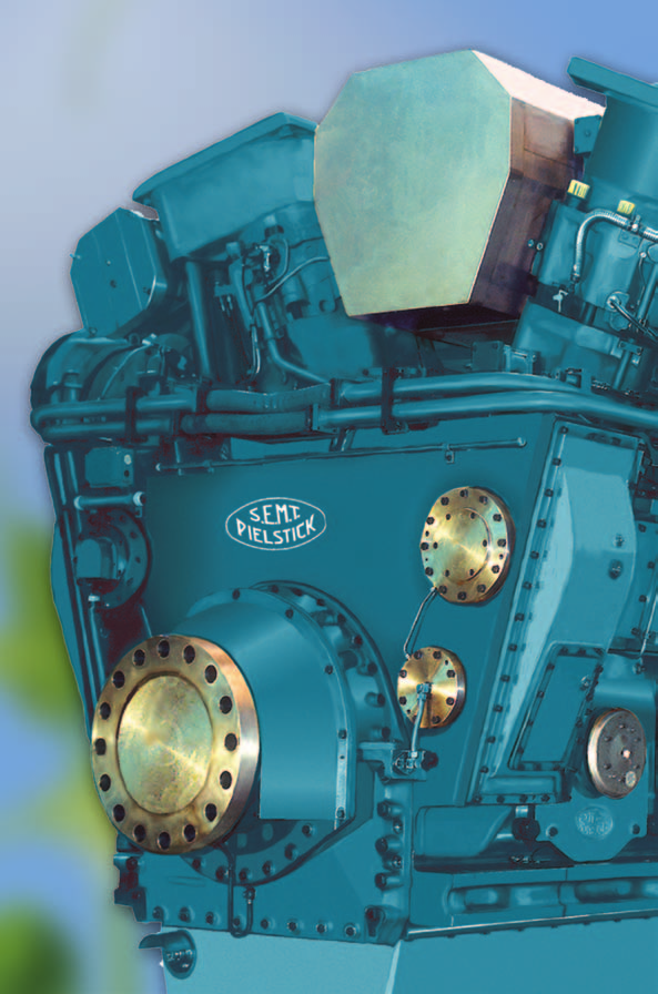
122 122
123 Bore: 400 mm, Stroke: 500 mm Speed r/min 600 mep bar 23.9 kw 12PC2.6 B 9,000 14PC2.6 B 10,500 16PC2.6 B 12,000 S.E.M.T. Pielstick PC2.6 B Specific Fuel Oil Consumption (SFOC) to ISO conditions MCR 100% 85% PC2.6 B - 1) - 1) Dimensions Cyl. No L mm 9,100 9,840 10,580 L 1 mm 5,960 6,700 7,440 W mm 3,780 3,780 3,780 H mm 4,800 4,800 4,800 Dry mass t ) SFOC values are project specific. Please contact MAN Diesel & Turbo for further information W H L L1 123
124 S.E.M.T. Pielstick PA6 B STC Bore: 280 mm, Stroke: 330 mm Speed r/min 1050 mep bar 22.8 kw* 12PA6 B STC 4,860 16PA6 B STC 6,480 20PA6 B STC 8,100 Specific Fuel Oil Consumption (SFOC) to ISO conditions MCR 100% 85% PA6 B STC - 1) - 1) Dimensions Cyl. No L mm 5,830 6,780 7,960 W mm 2,340 2,340 2,640 H mm 3,124 3,124 3,166 Dry mass t Engine fuel: Distillate according to ISO 8217 DMA Engine rating: engine rating according to ISO 3046 conditions * 110% load for navy application for vessels with approval according to HSVR from DNV available 1 hour of 6 hours of engine operating time on special request 1) SFOC values are project specific. Please contact MAN Diesel & Turbo for further information. W H L 124

125 S.E.M.T. Pielstick Medium Speed Marine GenSets
126 S.E.M.T. Pielstick PA6 B Bore 280 mm, Stroke 330 mm Speed r/min Frequency Hz Eng. kw Gen. kw* Eng. kw Gen. kw* 12PA6 B 4,440 4,307 4,200 4,074 16PA6 B 5,920 5,742 5,600 5,432 18PA6 B 6,660 6,460 6,300 6,111 20PA6 B 7,400 7,178 7,000 6,790 Dimensions Cyl. No A mm 4,510 5,430 5,890 6,350 B mm 4,600 4,800 4,933 5,000 C mm 6,840 7,760 8,220 8,680 Dry mass t * Nominal generator efficiencies: 97% Engine fuel: Distillate according to ISO 8217 DMA A B 3,935 C 2,

127 MAN Medium Speed Propulsion systems


128 Fixed Pitch Propeller Programme The MAN Alpha FPP portfolio covers: power range of 4-40 MW per shaft blade configurations for 3, 4, 5 and 6-bladed propellers propellers with integrated shaft line and stern tube solutions a wide range of stern tube lube and sealing systems oil, water, biodegradable oils The MAN Alpha FPP's are characterised by the following benefits: high-efficient hydrodynamically optimised blade profiles Kappel designs available high reliability: Robust approach with ample mechanical design margins high-efficient aft ship integration with rudder, rudder bulb, ducts, etc. layouts for complete propulsion systems plant calculations with upfront consideration to TVC, alignment and control systems 128
129 MAN Medium Speed Propulsion Systems MAN Alpha controllable Pitch Propeller as standard Mk 5 versions are 4-bladed and 5-bladed versions are available upon request the figures stated after VBS indicate the propeller hub diameter standard blade/hub materials are Ni-Al-bronze, stainless steel is optional the propellers are available up to the highest ice classes. The below standard programmes, however, are based on no ice. 10,000 VBS Mk 3 CP Propeller Programme 9,000 Propeller diameter (mm) Propeller diameter (mm) 8,000 7,000 6,000 5,000 4,000 3,000 2,000 1,000 11,000 10,000 9,000 8,000 7,000 6,000 5,000 4, ,000 2,000 1,000 VBS790 VBS720 VBS660 VBS600 VBS1180 VBS1080 VBS980 VBS860 VBS740 VBS640 5,000 VBS860 VBS940 10,000 15,000 20,000 25,000 30,000 35,000 40,000 VBS1020 VBS1100 VBS Mk 5 CP Propeller Programme VBS1180 VBS1260 VBS1350 VBS1560 VBS1460 VBS1380 VBS1280 VBS1450 VBS1550 VBS1640 VBS1730 VBS1810 VBS1890 VBS1680 VBS1970 Engine Power (kw) VBS2060 VBS1940 VBS1800 VBS2150 Hub sizes: Small: VBS Medium: VBS Large: VBS VBS2240 VBS ,000 10,000 15,000 20,000 25,000 30,000 35,000 40,000 45,000 50,000 55,000 Engine Power [kw] 129
130 MAN Standard Package Examples Cyl. kw Prop. speed r/min D mm Hub VBS mm Q mm R mm W min mm K mm Gear mass t Prop. mass t* L58/64 6 8, ,500 1, ,115 2,200 2, , ,100 1, ,115 2,350 2, , ,100 1,560 1,190 1,305 2,550 2, , ,650 1, ,115 2,200 2, , ,300 1,380 1,050 1,175 2,350 2, , ,300 1,560 1,190 1,305 2,570 2, , ,800 1,380 1,050 1,175 2,270 2, , ,500 1,460 1,110 1,220 2,350 2, , ,500 1,680 1,280 1,380 2,570 3, , ,950 1,380 1,050 1,175 2,350 2, , ,650 1,560 1,190 1,305 2,550 2, , ,700 1,680 1,280 1,380 2,570 3, V48/60CR 12 14, ,950 1,460 1,100 1,170 2,676 2, , ,600 1,560 1,175 1,242 2,676 2, , ,600 1,680 1,278 1,333 2,919 3, , ,100 1,560 1,175 1,242 2,651 2, , ,850 1,680 1,278 1,333 2,676 2, , ,850 1,800 1,370 1,227 2,920 3, , ,260 1,680 1,278 1,333 2,676 2, , ,050 1,800 1,370 1,227 2,920 3, , ,100 1,940 1,480 1,307 3,000 3, , ,400 1,680 1,278 1,333 2,676 2, , ,200 1,800 1,370 1,227 2,900 3, , ,300 1,940 1,480 1,307 3,000 3, L48/60CR 6 7, ,250 1, ,170 2, , ,800 1, ,075 2,500 2, , ,600 1,380 1,050 1,175 2,270 2, , ,400 1, ,075 2,170 2, , ,000 1,380 1,030 1,131 2,580 2, , ,850 1,460 1,100 1,170 2,657 2, , ,550 1, ,115 2,200 2, , ,150 1,380 1,030 1,131 2,500 2, , ,000 1,560 1,175 1,257 2,600 2, , ,700 1,380 1,030 1,131 2,500 2, , ,300 1,460 1,100 1,170 2,651 2, , ,200 1,560 1,190 1,350 2,550 2,
131 MAN Standard Package Examples Cyl. kw Prop. speed r/min D mm Hub VBS mm Q mm R mm W min mm K mm Gear mass t Prop. mass t* L35/44DF 6 3, , , , , ,400 1, , , , , , ,600 1, , , , , , ,750 1, , , , ,100 1, , ,800 1, , , , ,200 1, , ,000 1, * S min and propeller mass are based on 6,000 mm propeller shaft and 3,000 mm stern tube D Q R S~ 3000 W min K 131
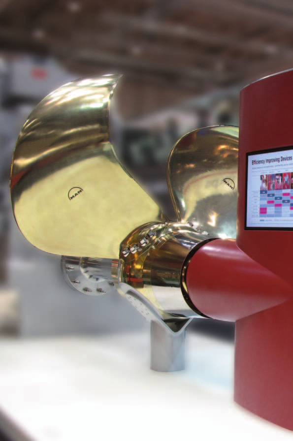
132 132
133 Cyl. kw Prop. speed r/min D mm Hub VBS mm V32/44CR 12 6, ,800 1, , ,400 1, , ,250 1, , ,950 1, , ,550 1, , ,400 1, , ,050 1, , ,650 1, , ,550 1, , ,150 1, , ,750 1, , ,700 1, , ,250 1, , ,850 1, , ,850 1,560 MAN Standard Package Examples L32/44CR 6 3, , , , , ,450 1, , , , ,950 1, , ,600 1, , ,600 1, , ,050 1, , ,750 1, , ,650 1, , ,150 1, , ,900 1, , ,700 1, , ,250 1, , ,000 1,280 * S min and propeller mass are based on 6,000 mm propeller shaft and 3,000 mm stern tube 133
134 MAN Standard Package Examples Cyl. kw Prop. speed r/min D mm Hub VBS mm Q mm R mm W min mm K mm Gear mass t Prop. mass t* V32/ , ,950 1, ,560 2, , ,400 1, ,630 2, , ,050 1, ,075 1,700 2, , ,100 1, ,630 2, , ,550 1, ,650 2, , ,250 1, ,075 1,700 2, , ,200 1, ,630 2, , ,700 1, ,700 2, , ,400 1,380 1,030 1,131 1,740 2, , ,300 1, ,021 1,650 2, , ,850 1, ,075 1,700 2, , ,600 1,460 1,100 1,170 1,780 2, L32/40 6 3, , ,400 1, , , ,520 1, , ,200 1, ,520 2, , , ,400 1, , , ,520 1, , ,400 1, ,560 2, , , ,520 1, , ,000 1, ,520 2, , ,550 1, ,630 2, , , ,520 1, , ,100 1, ,560 2, , ,650 1, ,630 2, * S min and propeller mass are based on 6,000 mm propeller shaft and 3,000 mm stern tube 134
135 Cyl. kw Prop. speed r/min D mm Hub VBS mm MAN Standard Package Examples Q mm R mm Wmin mm K mm Gear mass t Prop. mass t* L27/38 6 2, , ,300 2, , , ,300 2, , , ,400 2, , , ,400 2, , , ,400 3, , , ,300 2, , , ,400 2, , , ,400 2, , , ,450 2, , , ,500 3, , , ,400 2, , , ,400 2, , , ,450 2, , , ,450 2, , , ,500 3, , , ,400 2, , , ,400 2, , , ,400 2, , , ,500 2, , , ,550 3, * S min and propeller mass are based on 4,000 mm propeller shaft and 2,000 mm stern tube for 21/31, 27/38 and 6,000 mm propeller shaft and 3,000 mm stem tube for the other types D Q R S~2000 W min K 135
136 MAN Standard Package Examples Cyl. kw Prop. speed r/min D mm Hub VBS mm Q mm R mm W min mm K mm Gear mass t Prop. mass t* L21/31 6 1, , ,200 2, , , ,200 2, , , ,300 2, , , ,300 2, , , ,200 2, , , ,300 2, , , ,300 2, , , ,400 2, , , ,200 2, , , ,300 2, , , ,300 2, , , ,400 2, , , ,300 2, , , ,300 2, , , ,400 2, , , ,400 2, * S min and propeller mass are based on 4,000 mm propeller shaft and 2,000 mm stern tube for 21/31, 27/38 and 6,000 mm propeller shaft and 3,000 mm stem tube for the other types D Q R S~2000 W min K 136

137 MAN Exhaust Gas Turbochargers
138 MAN Exhaust Gas Turbochargers TCR and NR types with radial flow turbine and TCA and NA types with axial flow turbine straightforward design, uncooled gas casings, inboard bearing arrangement, plain bearings lube oil supply from the engine high availability, reliability, durability high efficiency easy maintenance and servicing long lifetimes of components long intervals between overhauls Applications for Marine and Stationary propulsion units generating sets diesel and dual fuel engines gas engines HFO engines Special tailormade solutions Power Turbines (PTG) Turbo Compound Systems (TCS - PTG) with Power Turbine Generator Variable Turbine Area (VTA) 138
139 MAN Exhaust Gas Turbochargers MAN Turbocharger application ranges TCA Compressor pressure ratio πc tot TCA33 TCA44 TCA55 TCA66 TCA77 TCA88 TCA33 TCA44 TCA55 TCA66 TCA77 TCA88 TCA44 TCA55 TCA66 TCA77 TCA88 TCA Compressor volume flow V C (m3 /s) four-stroke version two-stroke version MAN Turbocharger application ranges TCR 6.0 Total pressure ratio πc tot TCR10-42 TCR12-42 TCR14-42 TCR16-42 TCR18-42 TCR20-42 TCR22-42 TCR10-41 TCR12-41 TCR14-41 TCR16-41 TCR18-41 TCR20-41 TCR22-41 TCR18-2 TCR20-2 TCR Intake volume V C (m3 /s) high pressure four-stroke version standard four-stroke version two-stroke version 139

140 MAN TCA Series Main features Turbine type Axial flow turbine Max. permiss. temp. 500 C 2-stroke / 650 C 4-stroke Pressure ratio up to 5.5 Suitable for HFO, MDO, Gas Turbocharger programme Max. supercharged engine Turbocharger output kw Max. permissible type 2-stroke 4-stroke Speed Mass le* = 8.5 kg/kwh le* = 6.5 kg/kwh rpm kg TCA33-5,400 27,800 1,370 TCA44 6,500 7,900 22,700 1,950 TCA55 9,000 10,400 20,000 3,200 TCA66 13,200 14,800 16,900 5,300 TCA77 18,750 21,000 14,200 8,330 TCA88 28,500 30,000 12,000 14,000 * Specific air consumption 140

141 MAN TCR Series Main features Turbine type Radial flow turbine Max. permiss. temp. 650 C Pressure ratio up to 5.4 Suitable for HFO, MDO, Gas Turbocharger programme Max. supercharged engine Turbocharger output kw Max. permissible type 2-stroke 4-stroke Speed Mass le* = 7.5 kg/kwh le* = 6.5 kg/kwh rpm kg TCR , TCR , TCR14-1,300 58, TCR16-1,850 48, TCR18 2,500 2,750 40, TCR20 3,700 4,000 33, TCR22 6,600 6,850 25,600 1,050 * Specific air consumption 141

142 MAN NA/S/T9 Series Main features Turbine type Axial flow turbine Max. permiss. temp. 650 C Pressure ratio up to 4.5 Suitable for HFO, MDO, Gas Turbocharger programme Turbocharger Max. supercharged Max. permissible Mass type engine output kw speed rpm kg NA29/S 3,600 31,300 1,050 NA34/S 5,100 26,300 1,350 NA40/S 7,300 22,400 2,200 NA48/S 11,000 18,600 3,700 NA57/T9* 16,100 15,000 5,100 NA70/T9** 24,500 12,000 9,800 * Pressure ratio up to 4.2 ** Pressure ratio up to 4.0 Specific air consumption Ie = 6.5 kg/kwh 142

143 MAN NR/S Series Main features Turbine type Radial flow turbine Max. permiss. temp. 650 C (opt. 720 C) Pressure ratio up to 4.5 Suitable for HFO, MDO, Gas Turbocharger programme Turbocharger Max. supercharged Max. permissible Mass type engine output kw speed rpm kg NR12/S , NR14/S , NR17/S 1,350 52, NR20/S 1,870 44, NR24/S 2,690 37, NR29/S 3,820 31, NR34/S 5,400 26,300 1,450 Specific air consumption Ie = 7 kg/kwh 143
144 MAN (TCS-) PTG Power Turbines Exhaust Gas Turbine newly developed high efficiency turbine new turbine nozzle ring with extended life time bearing arrangement with long life time axial: Based on most modern TCA series radial: Based on most modern TCR series Gearbox high efficiency high speed gearbox reducing turbine speed to generator speed Couplings gearbox to generator: High flexible coupling Generator synchronous generator Exhaust Gas System control valves for power turbine operating range fast acting emergency valves for emergency shutdown control and saftey equipment Optional: Variable Turbine Area (VTA) for Exhaust Gas Turbine increasing efficiency and flexibility of operation Funnel (Boiler) Turbochargers Exhaust gas receiver Main engine Gearbox Coupling Generator Exhaust gas turbine Board grid 144


 PTG22 2,700 16.")
145 MAN (TCS-) PTG Power Turbines Main Features Power Turbines Turbine type Radial or Axial Max. permiss. temp. 550 ºC Output shaft speed 1,800 rpm (1,500 rpm) Suitable for HFO, MDO, Gas Radial flow turbine Max. output kw el T = 3.9 Max. flow rate kg/s Temperature before turbine 480 C Speed PT 1/min (TCS-) PTG18 1, ,000 (TCS-) PTG20 1, ,000 (TCS-) PTG22 2, ,000 Axial flow turbine (TCS-) PTG55 4, ,000 PTG TCS - PTG 145

146 MAN Variable Turbine Area (VTA) Variable Turbine Area (VTA) The VTA system consists of a nozzle ring equipped with adjustable vanes which optionally replace the fixed-vane nozzle rings in MAN Diesel & Turbo s standard TCA and TCR turbochargers. By altering the pitch of the adjustable vanes, the pressure of the exhaust gases on the turbine is regulated and thus the volume of charge air can be precisely matched to the quantity of injected fuel at all points in an engine s load and speed range. The result is reduced specific fuel consumption, reduced emissions HC and CO 2 and improved engine response. Benefits of VTA up to 5 g/kwh lower fuel consumption lower soot and smoke emission lower CO 2 emissions lower particle emissions suitable for TCA and TCR turbochargers retrofit packages short payback time VTA cuts fuel consumption and reduces emissions 146

147 Contacts
Marine Engine. IMO Tier ll and Tier lll Programme 2015
 Marine Engine IMO Tier ll and Tier lll Programme 2015 All data provided in this document is non-binding. This data serves informational purposes only and is especially not guaranteed in any way. Depending
A study into the fuel savings potential by a major rebuild of propulsion system
 A study into the fuel savings potential by a major rebuild of propulsion system Per Rønnedal Senior Manager New Design Research & Development Marine Low Speed < 1 > Agenda 1 Introduction of MAN and our
Ambient Temperature Operation and Matching MAN B&W Two-stroke Engines
 Ambient Temperature Operation and Matching MAN B&W Two-stroke Engines Content Introduction...5 Standard ambient matched engine...5 Operating at high seawater with standard matched engine...6 Non-standard
WÄRTSILÄ 50DF PRODUCT GUIDE
 WÄRTSILÄ 50DF PRODUCT GUIDE Introduction Introduction This Product Guide provides data and system proposals for the early design phase of marine engine installations. For contracted projects specific
32/40. Four-stroke diesel engine
 32/40 Four-stroke diesel engine MAN Diesel & Turbo The responsible way in leading technology MAN Diesel & Turbo is the world s leading designer and manufacturer of low and medium speed engines engines
VM 32. Efficiency and Performance New Product Development Modular Design 12 16 Cylinder
 VM 32 E with Efficiency and Performance New Product Development Modular Design 12 16 Cylinder VM 32 E Power Output 6,720 8,960 kw The new VM 32 E engine is designed for our offshore customers seeking the
L16/24 IMO Tier II Marine Generating Sets
 L16/24 IMO Tier II Marine Generating Sets MAN L16/24 GenSet power for marine applications The responsible way in leading technology MAN Diesel & Turbo is the world s leading designer and manufacturer of
Thermo Efficiency System. for Reduction of Fuel Consumption and CO 2 Emission
 Thermo Efficiency System for Reduction of Fuel Consumption and CO 2 Emission Contents Introduction...5 Description of the Thermo Efficiency System...6 Power concept and arrangement...6 Main engine performance
OUTCOME 2 INTERNAL COMBUSTION ENGINE PERFORMANCE. TUTORIAL No. 5 PERFORMANCE CHARACTERISTICS
 UNIT 61: ENGINEERING THERMODYNAMICS Unit code: D/601/1410 QCF level: 5 Credit value: 15 OUTCOME 2 INTERNAL COMBUSTION ENGINE PERFORMANCE TUTORIAL No. 5 PERFORMANCE CHARACTERISTICS 2 Be able to evaluate
Press Release Page 2 / 9
 Copenhagen, 07/0 MAN Diesel & Turbo Technology Boosts Efficiency WHR and TCS-PTG improve efficiency on large engines MAN Diesel & Turbo used the world premiere of its MAN B&W ME-GI gas engine in Copenhagen
MAN B&W K98ME-C6. Project Guide. Electronically Controlled Two stroke Engines
 MAN B&W K98ME-C6 Project Guide Electronically Controlled Twostroke Engines This Project Guide is intended to provide the information necessary for the layout of a marine propulsion plant. The information
Floating. Diesel power stations
 Floating Diesel power stations MAN Diesel & Turbo The responsible way in leading technology MAN Diesel & Turbo is the world s leading designer and manufacturer of low and medium speed engines. Our involvement
4000 Series 4008TAG2A Diesel Engine ElectropaK 947 kwm @ 1500 rpm
 The Perkins 4000 Series family of 6, 8, 12 and 16 cylinder diesel engines was designed in advance of today s uncompromising demands within the power generation industry and includes superior performance
WÄRTSILÄ 34DF PRODUCT GUIDE
 WÄRTSILÄ 34DF PRODUCT GUIDE Copyright by WÄRTSILÄ FINLAND Oy All rights reserved. No part of this document may be reproduced or copied in any form or by any means (electronic, mechanical, graphic, photocopying,
Energy Savings through Electric-assist Turbocharger for Marine Diesel Engines
 36 Energy Savings through Electric-assist Turbocharger for Marine Diesel Engines KEIICHI SHIRAISHI *1 YOSHIHISA ONO *2 YUKIO YAMASHITA *3 MUSASHI SAKAMOTO *3 The extremely slow steaming of ships has become
Bergen Engines Products and Applications
 Bergen Engines Products and Applications 1 Since 1948 Bergen Engines, a Rolls-Royce Power Systems Company, has delivered more than 6,500 four-stroke medium-speed diesel and gas engines for power generation
TYPE APPROVAL CERTIFICATION SCHEME MASS PRODUCED DIESEL ENGINES
 1. Introduction TYPE APPROVAL CERTIFICATION SCHEME MASS PRODUCED DIESEL ENGINES 1.1 This scheme details the tests and inspection of diesel engines manufactured by mass production system for use in marine
Specifications for Volkswagen Industrial Engine
 Volkswagen 1 industrial engine Specifications for Volkswagen Industrial Engine AFD 1.9 ltr. TDI diesel engine EURO 2 Volkswagen AG, Wolfsburg Volkswagen AG reserves the right to introduce amendments or
MAN 28/33D STC. Powerful and reliable
 MAN 28/33D STC Powerful and reliable MAN Diesel & Turbo Leading technology - the responsible way MAN Diesel & Turbo is the world s leading designer and manufacturer of low and medium speed engines engines
MAN Diesel & Turbo. Frederik Carstens Head of Offshore Sales Marine Medium Speed. Frederik Carstens & Karsten Borneman
 Frederik Carstens Head of Offshore Sales Marine Medium Speed < 1 > Disclaimer All data provided on the following slides is for information purposes only, explicitly non-binding and subject to changes without
Tier III emission technology
 Tier III emission technology By Johan Kaltoft, Senior Project Manager, Emission Reduction Technology < 1 > Tier III emission technology Tier III strategy SCR - Selective Catalytic Reduction EGR Exhaust
Marek Dzida Gdansk University of Technology Poland. 1. Introduction
 Possible Efficiency Increasing of Ship Propulsion and Marine Power Plant with the System Combined of Marine Diesel Engine, Gas Turbine and Steam Turbine 3 Marek Dzida Gdansk University of Technology Poland
1013 E. The engine for agricultural equipment.
 1013 E. The engine for agricultural equipment.... -186 kw at 2300 rpm These are the characteristics of the 1013 E: Modern water-cooled 4- and 6-cylinder in-line engine Turbocharging with charge air cooling
Engine room and performance data for 8G80ME-C9.5-GI-TII with high load tuning.
 Engine rm and perfrmance data fr 8G80ME-9.5-GI-TII with high lad tuning. Light running margin is 5%. Recmmended value is 3-7%. Pint Pwer kw Speed r/min MEP Bar SMR: Specified Maximum ntinuus Rating (100.0%
Current state of plant Functioning as a peak and emergency centre. Statistics Accumulated operating hours:
 Current state of plant Functioning as a peak and emergency centre Statistics Accumulated operating hours: D1-2-3-6-7: 43000 to 48000 hrs D4-5: 53000 to 57000 hrs D8: 33000 hrs Layout of the plant Index:
With the introduction of slide fuel valves, engine conditions for service at low loads for long term operation have been significantly improved.
 MAN Diesel MAN Diesel A/S Service Letter SL07-480/SBE June 2007 Low Load Operation for MC and ME engines Long Term Operation Mode Action Code: WHEN CONVENIENT In connection with requests from shipowners
912. The engine for construction equipment.
 912. The engine for construction equipment....... 24-82 kw at 1500-2500 min -1 These are the characteristics of the 912: Air-cooled 3-, 4-, 5-, 6-cylinder naturally aspirated in-line-engines. Direct injection.
Slow steaming a viable long-term option?
 Slow steaming a viable long-term option? AUTHOR: Andreas Wiesmann, General Manager Innovation & Business Development, Two-stroke, Wärtsilä Services The slow steaming of merchant ships, particularly container
C18 ACERT Fire Pump Tier 3 448 bkw/600 bhp @ 1750 rpm
 CATERPILLAR ENGINE SPECIFICATIONS I-6, 4-Stroke-Cycle Diesel Bore...145.0 mm (5.71 in) Stroke...183.0 mm (7.2 in) Displacement... 18.1 L (1,104.53 in3) Aspiration...Turbocharged Aftercooled Compression
THM Gas Turbines Heavy duty gas turbines for industrial applications
 THM Gas Turbines THM Gas Turbines Heavy duty gas turbines for industrial applications Combined advantages The THM 1304 heavy duty gas turbine family consists of two members with ISO power outputs of 10,500
Engine catalogue. Marine Diesel engines. MAN range - light duty
 Engine catalogue Marine Diesel engines MAN range - light duty ENG 10 November 2010 Marine Diesel engines Engine Power Num. of Displacement Design kw cylinders cm3 R6-730 537 6 12,8 inline R6-800 588 6
Copyright 2012 Mayekawa Mfg. Co.,Ltd. All Rights Reserved.
 MGO COOLING SYSTEM MAYEKAWA MFG. CO., LTD. Marine Division Ecology and Energy Dept. Copyright 2012 Mayekawa Mfg. Co.,Ltd. All Rights Reserved. Current regulation : New sulphur limits in marine fuel 1.
Diesel and gas engine systems for EURO VI on-highway applications
 Diesel and gas engine systems for EURO VI on-highway applications Mercedes-Benz engines in the OM 93X and OM 47X model series. Outstanding design and efficiency. Specifically developed to comply with the
Ship Propulsion/Electric Power Hybrid System Recovering Waste Heat of Marine Diesel Engine
 54 Ship Propulsion/Electric Power Hybrid System Recovering Waste Heat of Marine Diesel Engine SHINICHIRO EGASHIRA *1 TAKAHIRO MATSUO *2 YOSHIHIRO ICHIKI *3 To meet ship power demand, using a steam turbine-driven
Dual Fuel Medium Speed Product. Presenter Name Date
 Dual Fuel Medium Speed Product Presenter Name Date Contents Caterpillar, Inc. Overview Our Product Line Dual Fuel Product Dual Fuel Conversion Performance & Maintenance References Caterpillar, Inc. Making
Market Conditions, Achievements & Challenges, General Technical Update
 MAN Diesel & Turbo Technical Seminar, Nov 2015 Market Conditions, Achievements & Challenges, General Technical Update Presented by Ole Grøne Senior Vice President MAN Diesel & Turbo Copenhagen, Denmark
Fault codes DM1. Industrial engines DC09, DC13, DC16. Marine engines DI09, DI13, DI16 INSTALLATION MANUAL. 03:10 Issue 5.0 en-gb 1
 Fault codes DM1 Industrial engines DC09, DC13, DC16 Marine engines DI09, DI13, DI16 03:10 Issue 5.0 en-gb 1 DM1...3 Abbreviations...3 Fault type identifier...3...4 03:10 Issue 5.0 en-gb 2 DM1 DM1 Fault
Torino Nord. Cogeneration Plant. The gas turbine. The steam generator. The Torino Nord cogeneration plant produces electricity and heat for district
 PLANT TORINO NORD Iren Energia is the company in the Iren Group whose core businesses are the production and distribution of electricity, the production and distribution of thermal energy for district
TCA Turbocharger. The benchmark
 TCA Turbocharger The benchmark MAN Diesel & Turbo Aspiring to turbocharger perfection MAN Diesel & Turbo is the world s leading designer and manufacturer of large exhaust gas turbochargers for low and
Engine Power Plant 5,2 MW Stationary Dual Fuel (Diesel / Gas ) Engine (12 VDS 48/42 )
 Engine (12 VDS 48/42 )") Engine Power Plant 5,2 MW Stationary Dual Fuel (Diesel / Gas ) Engine (12 VDS 48/42 ) Table of Contents 1. General technical description 2. Specification of the equipment 2.1 Diesel / gas unit 2.2 Alternator
Engine Power Plant 5,2 MW Stationary Dual Fuel (Diesel / Gas ) Engine (12 VDS 48/42 ) Table of Contents 1. General technical description 2. Specification of the equipment 2.1 Diesel / gas unit 2.2 Alternator
Application and Design of the ebooster from BorgWarner
 Application and Design of the ebooster from BorgWarner Knowledge Library Knowledge Library Application and Design of the ebooster from BorgWarner With an electrically assisted compressor, the ebooster,
Technical Specification. Generating Set with Waukesha engine burning natural gas
 Technical Specification Generating Set with Waukesha engine burning natural gas The following presents the Gas Engine Generating Set (GEGS) APG1000 type, based on Waukesha gas engine 16V150LTD. Using the
POWER PLANT GAS CONVERSIONS WÄRTSILÄ SPARK IGNITED GAS ENGINE (SG) CONCEPT
 CONCEPT") POWER PLANT GAS CONVERSIONS WÄRTSILÄ SPARK IGNITED GAS ENGINE (SG) CONCEPT WÄRTSILÄ DUAL FUEL GAS ENGINE (DF) CONCEPT CONVERSION CONCEPTS BASED ON EXISTING WÄRTSILÄ VASA 32/32LN, WÄRTSILÄ 32 AND WÄRTSILÄ
POWER PLANT GAS CONVERSIONS WÄRTSILÄ SPARK IGNITED GAS ENGINE (SG) CONCEPT WÄRTSILÄ DUAL FUEL GAS ENGINE (DF) CONCEPT CONVERSION CONCEPTS BASED ON EXISTING WÄRTSILÄ VASA 32/32LN, WÄRTSILÄ 32 AND WÄRTSILÄ
M20C. Long-Stroke Diesel Engines for Maximum Efficiency and High Reliability 6 8 9
 M20C Long-Stroke Diesel Engines for Maximum Efficiency and High Reliability 6 8 9 M20C The Compact Long-Stroke Diesel Engine with Heavy Fuel Capability Launched in 1992, the M 20 series set a new milestone
TRITON V. Cylinder Pressure Monitoring CPM 500. Replaces mechanical indicators on diesel engines. Improves combustion
 TRITON V Cylinder Pressure Monitoring CPM 500 Replaces mechanical indicators on diesel engines Improves combustion Reduces fuel consumption and emissions Optimises engine settings Engine & Turbine Management
Titan Makina Ltd. Şti. 1160. Sok. No: 9 Ostim 06370 Ankara Tel: + 90 312 354 9977 Fax: + 90 312 385 5611 Web: www.titanltd.com.
 IS26 Concrete Spraying Machine IS26 Concrete Spraying Machine TECHNICAL SPECIFICATIONS Manipulator Max. vertical spraying reach : Max. horizontal spraying reach : Working lights : Spraying Head Rotation
an EnPro Industries company POWERSolutions
 an EnPro Industries company POWERSolutions Steadfast Performer, Trustworthy Reliability, and Relentless Dependability The FM/ALCO engine, a world renowned name well established as a workhorse and prime
APPLIED THERMODYNAMICS TUTORIAL 1 REVISION OF ISENTROPIC EFFICIENCY ADVANCED STEAM CYCLES
 APPLIED THERMODYNAMICS TUTORIAL 1 REVISION OF ISENTROPIC EFFICIENCY ADVANCED STEAM CYCLES INTRODUCTION This tutorial is designed for students wishing to extend their knowledge of thermodynamics to a more
Emission support system for calculation of energy demand and emissions of ships. Hans Otto Kristensen
 Emission support system for calculation of energy demand and emissions of ships By Hans Otto Kristensen 2 DTU Mechanical Engineering, Technical University of Denmark Content of presentation Project description
1 Air-to-Air AfterCooling. 2 Engine Only. Capacity will vary with radiator size and use. of cab heater.
 Diesel Truck Engine 3126B 175-330 hp 420-860 @ 1440 rpm Peak CATERPILLAR ENGINE SPECIFICATIONS 6-Cylinder, 4-Stroke-Cycle Diesel Bore in (mm)... 4.33 (110) Stroke in (mm)... 5.0 (127) Displacement cu in
Top Technology for Industry, Agriculture, Business and Communities
 Top Technology for Industry, Agriculture, Business and Communities CHP The Technology with a Potential for Saving Energy Combined Heat and Power (CHP) is a highly efficient technology for the conversion
EXPERIMENT NO. 3. Aim: To study the construction and working of 4- stroke petrol / diesel engine.
 EXPERIMENT NO. 3 Aim: To study the construction and working of 4- stroke petrol / diesel engine. Theory: A machine or device which derives heat from the combustion of fuel and converts part of this energy
BHKW. Power. Power. Gas engines for CHP units and gensets. MAN Engines. A Division of MAN Truck & Bus
 Power BHKW Power Gas engines for CHP units and gensets MAN Engines A Division of MAN Truck & Bus Contents Gas engines for cogenerating power stations... 3 Application type and product range.... 3 Servicing
Citius-sarjan merimoottorit
 Tech Library http://engine.od.ua SisuDiesel Citius-sarjan merimoottorit Puhdas ja vahva valinta Clean and durable choice SisuDiesel AGCO SISU POWER power for the world with over 60 years experience AGCO
Unit 96: Marine Propulsion Power Plant
 Unit 96: Marine Propulsion Power Plant Unit code: R/503/1756 QCF Level: 5 Credit value: 15 Aim This unit provides learners with an understanding of marine propulsion power plant. Learners will also gain
Turbo Tech 101 ( Basic )
") Turbo Tech 101 ( Basic ) How a Turbo System Works Engine power is proportional to the amount of air and fuel that can get into the cylinders. All things being equal, larger engines flow more air and as
Turbo Tech 101 ( Basic ) How a Turbo System Works Engine power is proportional to the amount of air and fuel that can get into the cylinders. All things being equal, larger engines flow more air and as
How To Power A Power Plant With Waste Heat
 Power Generation Siemens Organic Rankine Cycle Waste Heat Recovery with ORC Answers for energy. Table of Contents Requirements of the Future Power Supply without extra Fuel Siemens ORC-Module Typical Applications
Drying of Woody Biomass. Process Engineering / GEA Barr-Rosin
 Drying of Woody Biomass BioPro Expo & Marketplace / Atlanta, GA / March 14-16, 2011 Drying of Woody Biomass Conventional Direct Fired Dryer Technology Proprietary work of the Copyright Owner Issues with
HEAVY-DUTY, REDEFINED. REDEFINED.
 HEAVY-DUTY, REDEFINED. TO GET YOUR TOUGHEST JOBS DONE, you need an engine that works even harder than you do. That s why Caterpillar offers the CT13 engine for our vocational trucks. It delivers every
Possible Technical Modifications on Pre-2000 Marine Diesel Engines for NOx Reductions
 Possible Technical Modifications on Pre-2000 Marine Diesel Engines for NOx Reductions Report No. MPU 2008.017 Version 1/1 Department MPU Combustion Engines Environmental Contents Executive Summary 0 Introduction
1300 MAXTRAK SPECIFICATION
 CONE CRUSHER Crusher type: Liners: Standard concave: Lubrication: Adjustment: Control: Concave options: 1300 Automax Crusher. Manganese steel alloy mantle and concave. Medium Coarse. Pumped system having
HIGH PRESSURE TECHNOLOGY HYDRAULICS PNEUMATICS TESTING EQUIPMENT
 HIGH PRESSURE TECHNOLOGY HYDRAULICS PNEUMATICS TESTING EQUIPMENT MAXIMATOR GmbH 2 MAXIMATOR has an extensive know-how concerning concept, development, construction and manufacturing of test benches and
CAT CG132. Series Gas Generator Sets
 CAT CG132 Series Gas Generator Sets CAT CG132 SMARTER ENERGY SOLUTIONS COMMERCIAL AND INDUSTRIAL FACILITIES Facilities such as manufacturing plants, resorts, shopping centers, office or residential buildings,
Rickmeier Solutions. Gear pumps for superior Lubrication
 Rickmeier Solutions Gear pumps for superior Lubrication P U M P E N T E C H N O L O G I E #1. Introduction Position and significance of Rickmeier products Rickmeier supplies pumps, valves and systems for
COMPUTER MODEL TIL BEREGNING AF EEDI OG RØGGASEMISSIONER FOR FORSKELLIGE SKIBSTYPER
 COMPUTER MODEL TIL BEREGNING AF EEDI OG RØGGASEMISSIONER FOR FORSKELLIGE SKIBSTYPER HANS OTTO HOLMEGAARD KRISTENSEN CHEFKONSULENT, DANMARKS REDERIFORENING (HOK@SHIPOWNERS.DK) Generic ship model Skibsteknisk
1100 Series 1104C-44TAG2 Diesel Engine ElectropaK 99.5 kwm @ 1500 rpm
 Building upon Perkins proven reputation within the power generation industry, the Perkins 1100 Series range of ElectropaK engines now fit even closer to the needs of their customers. With this 1104C-44TAG2
SRS: THE STANDARDIZED REPOWERING SOLUTION FOR 300MW STEAM POWER PLANTS IN RUSSIA. Matthias Fränkle Siemens Power Generation (PG), Germany
, Germany") SRS: THE STANDARDIZED REPOWERING SOLUTION FOR 300MW STEAM POWER PLANTS IN RUSSIA Matthias Fränkle Siemens Power Generation (PG), Germany Page 1 of 11 1 Introduction Deregulation and competition are further
SRS: THE STANDARDIZED REPOWERING SOLUTION FOR 300MW STEAM POWER PLANTS IN RUSSIA Matthias Fränkle Siemens Power Generation (PG), Germany Page 1 of 11 1 Introduction Deregulation and competition are further
SCP 012-130 ISO. Other advantages: SCP 012-130 ISO is a series of piston pumps with a fixed displacement for mobile and stationary hydraulics.
 SCP 012-130 ISO is a series of piston pumps with a fixed displacement for mobile and stationary hydraulics. SCP 012-130 ISO covers the entire displacement range 12-130 cmᶟ rev. at a maximum pressure of
Section 11 - System Diagrams
 Section 11 System Diagrams Page 11-1 Section 11 - System Diagrams Section Contents Page Overview...11-3 Flow Diagram, Fuel System...11-4 Flow Diagrams, Lubricating Oil System...11-5 Flow Diagrams, Cooling
INTEC Engineering GmbH Heating Solutions for the Marine Industry
 INTEC Engineering GmbH Heating Solutions for the Marine Industry Thermal Oil Heaters Heating Solutions for the Marine Industry Compared to conventional plants using hot water or steam, thermal oil as a
EMISSIONS FROM MARINE ENGINES VERSUS IMO CERTIFICATION AND REQUIREMENTS OF TIER 3
 Journal of KONES Powertrain and Transport, Vol. 18, No. 2 2011 EMISSIONS FROM MARINE ENGINES VERSUS IMO CERTIFICATION AND REQUIREMENTS OF TIER 3 Jerzy Herdzik Gdynia Maritime University Marine Power Plant
D0834 LOH Performance diagrams. D0834 LOH Technical data. Engines. 162 kw 151 kw 132 kw. 162 kw. 151 kw 132 kw
 D0834 LOH D0834 LOH Performance diagrams Engines Piston displacement 4.6 liter bore 108 mm stroke 125 mm Power output for EURO 3, EURO 4, EURO 5 and EEV Emission standard EEV EURO 5 EURO 4 EURO 3 Engine
Jobson THE RIGHT CONTACT
 THE RIGHT CONTACT Jobson Italia srl was set up in 1990. The following services are rendered 365 days a year, 24 hours a day: Stocking and trading of spare parts: Main Engines, auxiliary engines, pumps,
Section 6 - System Diagrams
 Section 6 System Diagrams Page 6-1 Section 6 - System Diagrams Section Contents Page Overview...6-3 Flow Diagram, Fuel System...6-4 Flow Diagrams, Lubricating Oil System...6-5 Flow Diagrams, Cooling System...6-8
Perfectly Adapted. ISB Euro 6 Diesel Engines 150-310PS. Cummins Ltd. Address Line One Address Line Two Address Line Three
 Perfectly Adapted ISB Euro 6 Diesel Engines 150-310PS Cummins Ltd. Address Line One Address Line Two Address Line Three Tel: +00 0000 000000 Fax: +00 0000 000000 Internet: cummins.com Bulletin 0000000
US Heavy Duty Fleets - Fuel Economy
 US Heavy Duty Fleets - Fuel Economy Feb. 22, 2006 Anthony Greszler Vice President Advanced Engineering VOLVO POWERTRAIN CORPORATION Drivers for FE in HD Diesel Pending oil shortage Rapid oil price increases
Introductory Study of Variable Valve Actuation for Pneumatic Hybridization
 2007-01-0288 Introductory Study of Variable Valve Actuation for Pneumatic Hybridization Copyright 2007 SAE International Sasa Trajkovic, Per Tunestål and Bengt Johansson Division of Combustion Engines,
Radial piston pumps type R and RG
 Radial piston pumps type R and RG Operating pressure p max = 700 bar Delivery flow Q max = 91.2 lpm (at 1450 rpm) Geometric displacement V g max = 64.2 cm 3 /rev. 1. General Motor pumps and hydraulic power
Design and Operation of Fuel Efficient Ships. Jan de Kat Director, Energy Efficiency Operational and Environmental Performance Copenhagen
 Design and Operation of Fuel Efficient Ships Jan de Kat Director, Energy Efficiency Operational and Environmental Performance Copenhagen Genova 21 November 2013 Energy efficiency: key issues High fuel
How To Reduce Energy Efficiency On Ships
 Danish Society for Naval Architecture and Marine Engineering & Danish Maritime Society Energy Efficiency & SEEMP Copenhagen - October 28 th 2013 Carlos GUERRERO Business Development Manager Oil tankers
WÄRTSILÄ DYNAMIC MAINTENANCE PLANNING (DMP) AND CONDITION BASED MAINTENANCE (CBM) Wärtsilä
 AND CONDITION BASED MAINTENANCE (CBM) Wärtsilä") WÄRTSILÄ DYNAMIC MAINTENANCE PLANNING (DMP) AND CONDITION BASED MAINTENANCE (CBM) / 18 Wärtsilä Doc.ID: Revision: Status: Condition monitoring, Dynamic Maintenance Planning and Condition Based Maintenance
WÄRTSILÄ DYNAMIC MAINTENANCE PLANNING (DMP) AND CONDITION BASED MAINTENANCE (CBM) / 18 Wärtsilä Doc.ID: Revision: Status: Condition monitoring, Dynamic Maintenance Planning and Condition Based Maintenance
Marine after-treatment from STT Emtec AB
 Marine after-treatment from STT Emtec AB For Your Vessel and the Environment 6 7 8 1 11 1 10 9 1. Pick up. Flow direction valve. Filters. Cooler. Condensate trap 6. Flow meter 7. EGR-valve 8. Secondary
CREATING POWER SOLUTIONS. 2L41C 3L41C 3L43C 4L41C 4L42C 4L43C. Hatz Diesel. www.hatz-diesel.com
 CREATING POWER SOLUTIONS. 2L41C 3L41C 3L43C 4L41C 4L42C 4L43C Hatz Diesel EN www.hatz-diesel.com Exhaust gas recirculation (EGR) For years already the Hatz 4L42C has been successfully fitted with a robustly
1.3 Turbochargers are categorised in three groups depending on served power by cylinder groups with:
 (Feb 2015) Turbochargers 1. Scope 1.1 These requirements are applicable for s with regard to design approval, type testing and certification and their matching on engines. Turbochargers are to be type
Engine Heat Transfer. Engine Heat Transfer
 Engine Heat Transfer 1. Impact of heat transfer on engine operation 2. Heat transfer environment 3. Energy flow in an engine 4. Engine heat transfer Fundamentals Spark-ignition engine heat transfer Diesel
Why and How we Use Capacity Control
 Why and How we Use Capacity Control On refrigeration and air conditioning applications where the load may vary over a wide range, due to lighting, occupancy, product loading, ambient weather variations,
Principles of Engine Operation
 Internal Combustion Engines ME 422 Yeditepe Üniversitesi Principles of Engine Operation Prof.Dr. Cem Soruşbay Information Prof.Dr. Cem Soruşbay İstanbul Teknik Üniversitesi Makina Fakültesi Otomotiv Laboratuvarı
Automatic Back-Flushing Filter AutoFilt RF9.
 Automatic Back-Flushing Filter AutoFilt RF9. AutoFilt RF9 Clearing the Way. The Challenge: In response to the Tier III standard which will come into effect in 2016, the International Maritime Organization
V35/44G Four-stroke gas engine
 V35/44G Four-stroke gas engine MAN Diesel & Turbo is the world s leading designer and manufacturer of low and medium speed engines. With our range of large stationary gas and diesel engines, we are a reliable
Screw Compressors ESM 30 132 Fixed Speed & VS 30 132 Variable Speed
 Screw Compressors ESM 30 132 Fixed Speed & VS 30 132 Variable Speed Rely on GD to provide the perfect fit The perfect fit to maximise productivity The growing industrial demand for compressed air requires
INDUSTRIAL DIRECT DRIVEN PISTON COMPRESSORS CL - CH - CK
 INDUSTRIAL DIRECT DRIVEN PISTON COMPRESSORS CL - CH - CK CL - CH - CK Direct driven solution for industry Proven technology, solid construction The CL - CH - CK units are directly driven air-cooled, single
Delphi E3 Diesel Electronic Unit Injector
 Delphi E3 Diesel Electronic Unit Injector The Delphi E3 Diesel Electronic Unit Injector (EUI), was introduced for the 2002 EGR equipped diesel engines onhighway heavy duty applications. A version of this
Micro cogeneration. Affordable, efficient and innovative
 Micro cogeneration Affordable, efficient and innovative A compact and efficient solution A compact and efficient solution Organisations are increasingly looking for environmentally friendly systems to
Atlas Copco Stationary air compressors
 Atlas Copco Stationary air compressors Oil-free and oil lubricated piston compressor 2.2 - kw / 3-7.5 hp QUALITY COMPRESSORS DESIGNED SPECIFICALLY FOR THE SNOW MAKING INDUSTRY Atlas Copco's L-range of
Marine after-treatment from STT Emtec AB
 Marine after-treatment from STT Emtec AB For Your Vessel and the Environment SCR Technology How it works The selective catalytic reduction of nitrous oxides (NOx) by nitrogen compounds such as urea solutions
IEA Workshop Copenhagen Small scale biomass co-generation with modern steam engines
 IEA Workshop Copenhagen Small scale biomass co-generation with modern steam engines Dipl.-Ing. Till Augustin October, 7 th 2010 Solid Biomass Cogeneration with Spilling Steam Engines Contents: Who is Spilling
1. A belt pulley is 3 ft. in diameter and rotates at 250 rpm. The belt which is 5 ins. wide makes an angle of contact of 190 over the pulley.
 Sample Questions REVISED FIRST CLASS PARTS A1, A2, AND A3 (NOTE: these questions are intended as representations of the style of questions that may appear on examinations. They are not intended as study
Service Experience. MAN B&W Two-stroke Engines
 Service Experience MAN B&W Two-stroke Engines Content Introduction...5 Cold Corrosion Control...5 Introduction of BN 100 cylinder oils...5 Increased jacket cooling water temperatures various systems...9
N/NH Truck-mounted fire pump series
 N/NH Truck-mounted fire pump series Normal pressure pump type N Combined normal- and high-pressure fire pump type NH Certified according to EN 1028 and UL classified Rosenbauer - N/NH Truck-mounted fire
Jeep Renegade Technical specifications
 Jeep Renegade Technical specifications Specifications are based on the latest product information available at the time of publication. All dimensions are in millimeters at curb weight and with standard