USE AND MAINTENANCE MANUAL
|
|
|
- Lorena Patrick
- 7 years ago
- Views:
Transcription
1 Note: the numbers in parenthesis refer to the components in the exploded view of page 3. VALBIA supplies pneumatic rotary actuators, RACK and PINION Design, quarter turn, with rotation 0-180, Double Acting type, from model 5 to 160. CAUTION: Remove from the actuator all dust that may cause sparks; clean periodically to prevent dusting on the actuator. Do not hit the actuators with metallic objects, as they may give off sparks. TABLE OF CONTENTS : 0. WARNING 1. SERVICE CONDITIONS. FUNCTION 3. STORAGE 4. MAINTENANCE 5. EXPLODED VIEW 6. DISASSEMBLING 7. ASSEMBLING 8. ADJUSTMENT 0 Warning The installation and the maintenance of pneumatic actuators must be assigned to trained and qualified personnel. The use of the actuators out of the allowed temperature and pressure ranges may cause damage to the internal and external components. Prior to any installation and maintenance of the actuator, close and disconnect any kind of power or air supply. Disassembling the spring return type actuators (springs inside) may cause severe injuries. The maintenance must be assigned to qualified expert personnel in full observance of the instruction described at paragraph 5 Otherwise the actuator has to be returned to VALBIA. 1 Service conditions AIR SUPPLY: dehumidified or lubricated air (standard). Other non corrosive gases or fluids are a possible alternative option, if compatible to the materials of the actuator components (internal parts and lubricant). WORKING PRESSURE : min.,5 bar - max 8 bar TEMPERATURE : min. -0 C to max C - standard execution - NBR gaskets min. -0 C to max C - HIGH temperature execution - FKM ( Viton ) gaskets min. -40 C to max C - LOW temperature execution - silicone gaskets Warning: in case of high or low temp. executions a special grease is used as lubricant and such conditions may alter the torque generated by the actuator. For further information please refer to VALBIA ROTATION: half turn, adjustable +5 for the open position, and 5 in close position. LUBRICATION: The actuators are equipped with filled-for-life lubrication for normal service conditions. OPERATING TIME : please refer to the technical documentation. The operating time depends on various parameters such as air supply pressure, capacity of the air supply installation (size of piping, control equipment), type of valve and fluid, selected safety factor, temperature etc. Pag. 1 di 7 Rev.0 Maggio 015 Manuale Series 83 rev_00 en

.")
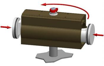
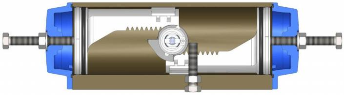
2 Function The air pressure acts on the surface of the pistons ( 1) causing their alternate movement, which is converted into rotation ( standard ) of the pinion ( ). As a result the pneumatic actuators can be used for remote operation of the valves. CHIUSO / CLOSED F 1 F P1 Supplying air through port P1 the external chambers fill up and the pressure on the surface of the pistons (1) creates a force (F) pushing them close to the pinion, generating a torque with CLOCKWISE rotation (top view). APERTO / OPEN 1 F1 F1 P When the pistons (1) are closed to the oinion, supplying air through port P, the internal chamber fill up and the pressure on the surface of the pistons creates a force (F1) pushing them away from each other, generating a torque with COUNTECLOCKWISE rotation (top view). 3 Storage It is recommended that the actuator be kept in clean and dry place. The state of preservation during the storage time is improved if the actuator is preserved in the original packing box. For a long storage period we recommend to effect periodically one complete cycling by pressurizing the chambers. The actuators have two air ports which should be plugged during storage to avoid any intrusion Pag. di 7 Rev.0 Maggio 015 Manuale Series 83 rev_00 en
 in appropriate kits ( except for lubricating grease). The maintenance may become necessary between 500.000")
3 4 Maintenance The maintenance of the actuator is permitted to Valbia personnel or to properly trained personnel. Valbia supplies the spare parts (gaskets, guide elements) in appropriate kits ( except for lubricating grease). The maintenance may become necessary between and cycles, according to the local service conditions. 5 Exploded view Exploded view for actuators from mod 5 to 160 Pos. DESCRIZIONE / Description MATERIALE / Material TRATTAMENTO / Treatment Q.TA 1 Corpo - Body Alluminio estruso - Extruded aluminium Ossidato duro - Hard anodized 1 Pignone antiespulsione - Anti-blowout pinion Acciaio - Steel Nichelato - Nickel plated 1 * 3 O-ring NBR 1 * 4 Anello distanziale - spacer ring POM 1 * 5 O-ring NBR 1 * 6 O-ring NBR 1 7 Camma - Cam Acciaio inox - Stainless steel 1 8 Anello camma spacer POM 1 * 9 Anello sotto Seeger spacer POM 1 10 Rondella washer Acciaio inox - Stainless steel 1 **11 Seeger - snap ring Acciaio - Steel Nichelato - Nickel plated 1 1 Pistone Piston Alluminio pressofuso - Die cast aluminium * 13 O-ring NBR * 14 Anello antifrizione - Antifriction ring POM * 15 Pattino reggispinta - thrust block POM [4] 16 Dado di bloccaggio reg. - Stop bolt retaining nut Acciaio inox - Stainless steel 1 17 Vite di regolazione - Stop bolt Acciaio inox - Stainless steel 1 18 Tappo sinistro - Left end cap Alluminio pressofuso - Die cast aluminium Verniciato - Painted 1 19 Tappo destro - Right end cap Alluminio pressofuso - Die cast aluminium Verniciato - Painted 1 0 Guarnizioni Tappi - End cap seats NBR 1 O-ring NBR Vite di serraggio tappi - End cap fixing screw Acciaio inox - Stainless steel 8 Pag. 3 di 7 Rev.0 Maggio 015 Manuale Series 83 rev_00 en

![position indicator Gomma termoplastica TPE Thermoplastic rubber TPE 1 [x] mod.](/docs-images/60/44801395/images/4-1.png "140-160 * Part subject to wear ** Reinforced series DIN471 - UNI 7436 6 Disassembling CAUTION : it is recommended to use suitable safety equipment during the handling for maintenance because of heavy")

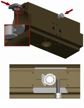
4 3 Vite di regolazione - Stop bolt Acciaio inox - Stainless steel 4 Dado di bloccaggio reg. - Stop bolt retaining nut Acciaio inox - Stainless steel 5 Rondella washer Acciaio inox - Stainless steel 6 O-ring NBR 7 Rondella washer Acciaio inox - Stainless steel 8 Indicatore di posizione - position indicator Gomma termoplastica TPE Thermoplastic rubber TPE 1 [x] mod * Part subject to wear ** Reinforced series DIN471 - UNI Disassembling CAUTION : it is recommended to use suitable safety equipment during the handling for maintenance because of heavy and/or bulky parts. 1. Disconnect pneumatic and electric supplies from the actuator;. After having disconnected their power supply, remove carefully any accessory attached to the actuator, preventing any damage during the handling; 3. Detach the actuator from the valve taking carefully note of all references that may be helpful for the attachment after maintenance; 4. Place the actuator on a support with a square of the same size of the pinion ( ) so as to easily execute the below listed operation (see Fig. 1): 5. Disassemble the end caps (18-19), unscrew in crossed sequence the screws ( ) (see Fig. ; 6. Loosen nuts ( 16 ) and unscrew completely screws ( 17 ) see Fig. 3 ; 7. Rotate the cylinder ( 1 ) in CLOCKWISE direction (top view) holding the pinion ( ) so as to release the rack of the pistons ( 1 ) from the pinion ( ) and to push the pistons towards to the cylinder ends. Now both pistons ( 1 ) can be removed see Fig. 4. NOTE: Do not use compressed air to remove the pistons ( 1 ) from the cylinder ( 1 ); 8. Remove the indicator (8) from the pinion ( ), the seeger ( 11 ), the spacer ( 10 ), the washer (9) and the O-ring ( 6 ) see Fig. 5 ; 9. Extract the pinion () from the cylinder (1) by pushing it down, with special caution for all sealings, see Fig. 5 (if necessary use a rubber hammer); 10. Remove the cam (7) from the cylinder (1) sliding it out see Fig Fig.1 Fig. Fig Pag. 4 di 7 Rev.0 Maggio 015 Manuale Series 83 rev_00 en
 on a support with a square of the same size of the female attachment. Make sure that the pinion is provided with lower O-ring ( 3 ), spacer ( 4 ) and upper O-ring ( 5 ).")
5 Fig.4 Fig.5 7 Assembling CAUTION : It is recommended to use suitable safety equipment during the handling for maintenance because of heavy and/or bulky parts. 1. Before assembling clean all components preferably with degreaser.. Place the pinion ( ) on a support with a square of the same size of the female attachment. Make sure that the pinion is provided with lower O-ring ( 3 ), spacer ( 4 ) and upper O-ring ( 5 ). Lubricate the O-rings (see arrows fig. 6) ; The recommended lubricating grease is HELIOS SYNTH 1EP 3. Screw the adjustment screw ( 17 ) with nut ( 16 ) in the right adjustment hole of the cylinder ( 1 ) and let the cam ( 7 ) with o-ring ( 8 ) slide down on the guiding rail on the cylinder ( 1 ) (see detail A Fig.7) until it stops against the screw; 4. Lay the cylinder ( 1 ) down on the pinion ( ) holding it with the NAMUR surface rotated by approx. 50 to the upper slot of the pinion, see fig. 15 ; 5. Fit on the pinion ( ) the O-ring ( 6 ), the spacer ( 9 ), the washer ( 10 ), the seeger ( 11 ), the indicator (8), see Fig. 9 ; ATTENTION : verify the perfect closure of the seeger. 6. Grease the internal chamber of the cylinder ( 1 ) and both pistons ( 1 ) provided with O-ring ( 13 ) antifriction ring ( 14 ) and thrust block ( 15 ) and washer ( 7 ) - The recommended lubricating grease is HELIOS SYNTH 1EP. 7. For the standard execution (clockwise rotation opens) insert the pistons ( 1 ) into the cylinder ( 1 ) while turning the cylinder ( 1 ) in counterclockwise direction ( top view) until the pistons come into contact, see fig. 10 ; 8. Adjust the close position - see paragraph 8; 9. Assemble the end cap ( ) with O-ring ( 1 ) gasket ( 0 ), screw (3), o-ring (6), washer (5) and nut (4) on the cylinder (1) and screw down in crossed sequence the screws ( ), see fig. 11. Repeat the operation on the opposite side. 10. Adjust the open position through the screw (3) into the end caps (18-19) see paragraph 8; 11. Execute some test cycles to check the correct functioning of the actuator before Pag. 5 di 7 Rev.0 Maggio 015 Manuale Series 83 rev_00 en


6 DET. A Fig.6 Fig.7 Fig.8 Fig Fig.10 Fig.11 8 Adjustment Unscrewing completely the end caps screws (A) it is fixed the open position at see Fig. 1, while the close position is fixed thought the end stop bolt (C) see Fig. 13. A A Fig.1 Pag. 6 di 7 Rev.0 Maggio 015 Manuale Series 83 rev_00 en
 maintaining the same position for both; Put the actuator in open position and")
7 Fig.13 C N.B. : During the adjustment do not block the pinion on the support 8.1 Adjustment procedure, actuator in open position Put the actuator in closed position; Adjust the end caps screws (A-A) maintaining the same position for both; Put the actuator in open position and check the adjustment; Repeat the operation until the achievement of the desired adjustment; Keep the screw in the desired position and tight the nut. 8. Adjustment procedure, actuator in close position Put the actuator in open position; Ad just the end caps screws ( C ); Put the actuator in closed position and check the adjustment; Repeat the operation until the achievement of the desired adjustment; Keep the screw in the desired position and tight the nut; Pag. 7 di 7 Rev.0 Maggio 015 Manuale Series 83 rev_00 en
ABV20 Air Actuated Boiler Blowdown Valve Installation and Maintenance Instructions
 4057250/8 IM-P405-16 AB Issue 8 ABV20 Air Actuated Boiler Blowdown Valve Installation and Maintenance Instructions 1 General safety information 2 General product information 3 Installation 4 Operation
BETTIS CONVERSION INSTRUCTIONS TO CONVERT HD SERIES ACTUATORS TO HD-M3, HD-SR-M3 HD-M3HW OR HD-SR-M3HW SERIES PNEUMATIC ACTUATORS
 BETTIS CONVERSION INSTRUCTIONS TO CONVERT HD SERIES ACTUATORS TO HD-M3, HD-SR-M3 HD-M3HW OR HD-SR-M3HW SERIES PNEUMATIC ACTUATORS PART NUMBER: 132581 REVISION: A RELEASE DATE: 24 March 2000 Page 1 of 10
Tyco PremiAir Pneumatic Actuators
 A comprehensive range of pneumatic actuators, conforming to EN ISO 5211, providing compact, reliable and economical powered operation for all types of quarter turn valves. Features Mounting to valve either
Pneumatic actuators The Original! Technics of the top class.
 Automatic valves Actuators Accessories Pneumatic actuators The Original! Technics of the top class. Leaflet no. S1-01e-13 Table of contents Advantages and your benefits...page 3 Figure: actuator...page
OPERATING and MAINTENANCE MANUAL SERIES 2700A CONTROL VALVE CONTENTS. INTRODUCTION...1 Scope...1 Description...1 Valve Identification...
 OPERATING and MAINTENANCE MANUAL SERIES 2700A CONTROL VALVE CONTENTS INTRODUCTION...1 Scope...1 Description...1 Valve Identification...2 1.0 VALVE INSTALLATION...2 2.0 VALVE MAINTENANCE...3 Actuator Disassembly...3
IMPORTANT DOCUMENTATION DO NOT DISCARD!
 PART NO.: 6441-263C SERIES GRT 3 JAW PARALLEL GRIPPERS INFORMATION SHEET IMPORTANT DOCUMENTATION DO NOT DISCARD! Use this information sheet to assist with gripper installation and setup. File with maintenance
Round Housing with Side Ports
 Power Steering Steering Control Unit (SCU) Parts and Repair Information 5 Series Steering Control Units 001 Square Housing with Side Ports Round Housing with Side Ports T E L RP Round Housing with End
Fisher 1052 Size 20 Diaphragm Rotary Actuator with F and G Mounting Adaptation
 Instruction Manual 1052 Size 20 Actuator (F & G) Fisher 1052 Size 20 Diaphragm Rotary Actuator with F and G Mounting Adaptation Contents Introduction... 1 Scope of manual... 1 Description... 1 Specifications...
STORAGE, INSTALLATION AND MAINTENANCE PROCEDURES
 GATE VALVE O.S. & Y 1.0 Periodic Inspections 1.1 The valve stem packing should be inspected at least monthly. If the stem packing shows signs of leakage, simply tighten the adjusting nuts to compress the
S GATE KNIFE GATE VALVE WITH PNEUMATIC ACTUATOR
 MAIN FEATURES The pneumatic S GATE knife gate valve is intended for the automatic shut off of pipes of the heavy fluids like slurries and powders. The main fields of application are the water treatment,
Volkswagen Jetta, Golf, GTI 1999, 2000 2.8 Liter VR6 2V Engine Mechanical, Engine Code(s): AFP 17 Engine-Lubrication (Page GR-17)
: AFP 17 Engine-Lubrication (Page GR-17)") 17 Engine-Lubrication (Page GR-17) Lubrication system components, removing and installing Oil filter housing, disassembling and assembling Oil pan, removing and installing Oil pressure and oil pressure
17 Engine-Lubrication (Page GR-17) Lubrication system components, removing and installing Oil filter housing, disassembling and assembling Oil pan, removing and installing Oil pressure and oil pressure
1 Important Safety Procedures. Qualified maintenance personnel should read and follow these straightforward instructions.
 Installation, Operating and Maintenance Instructions XL Series Actuators Contents Important Safety Procedures Mounting and Operating Instructions Piping Instructions Solenoid Valves on Spring Return Actuators
Norbro Series 40R Pneumatic Actuator Double Acting or Spring Return
 Pneumatic Actuator Double Acting or Spring Return Since the mid-sixties the Norbro name has been recognised as the leading quarter turn actuator for industry. As proof of this, Norbro pneumatic actuators
RUBBER SLEEVE KNIFE GATE VALVE
 RUBBER SLEEVE KNIFE GATE VALVE The model knife gate is a wafer valve designed for a wide range of industrial applications. The double-seated design provides bi-directional shut off. The design of the valve
Instruction Manual. Alfa Laval SB Membrane Sample Valve ESE02963-EN1 2015-10. www.sks-online.com www.sks-webshop.com.
 Instruction Manual Alfa Laval SB Membrane Sample Valve ESE02963-EN1 2015-10 Original manual Table of contents The information herein is correct at the time of issue but may be subject to change without
Volkswagen New Beetle 2.0 Liter 4-cyl General, Engine (Engine Code AEG) 17 Engine-Lubrication system (Page GR-17)
 17 Engine-Lubrication system (Page GR-17)") 17 Engine-Lubrication system (Page GR-17) Lubrication system components, removing and installing Oil pan, removing and installing Oil pressure and oil pressure switch, checking Dynamic oil pressure warning
17 Engine-Lubrication system (Page GR-17) Lubrication system components, removing and installing Oil pan, removing and installing Oil pressure and oil pressure switch, checking Dynamic oil pressure warning
BUTTERFLY VALVES API 609 WAFER LUG U-SECTION BODY STYLE DIAPHRAGM VALVES EN13397:2000 WEIR BODY STYLE
 CATALOGUE 2012 - PART 2 WATER TREATMENT BUTTERFLY VALVES API 609 WAFER LUG U-SECTION BODY STYLE DIAPHRAGM VALVES EN13397:2000 WEIR BODY STYLE DIAPHRAGM VALVES EN13397:2000 STRAIGHT- THROUGH BODY STYLE
Rotary Actuators, NAMUR interface VDI/VDE 3845 & ISO 5211 (ATEX certified) Series ARP
 Series ARP") NORTH AMERICAN CYLINDER & ACTUATOR CATALOG > Release 8. Rotary Actuators and Grippers Rotary Actuators, NAMUR interface VDI/VDE 384 & ISO 211 (ATEX certified) Series ARP Model: Rack & Pinion - Rotational
NORTH AMERICAN CYLINDER & ACTUATOR CATALOG > Release 8. Rotary Actuators and Grippers Rotary Actuators, NAMUR interface VDI/VDE 384 & ISO 211 (ATEX certified) Series ARP Model: Rack & Pinion - Rotational
HYDRAULIC LIFT TABLE CART 2200-LB.
 HYDRAULIC LIFT TABLE CART 2200-LB. OWNER S MANUAL WARNING: Read carefully and understand all MACHINE ADJUSTMENT AND OPERATION INSTRUCTIONS before operating. Failure to follow the safety rules and other
300 SERIES 331, 332, 333, 344, 356 AND 367 MODELS
 Section: MOYNO 500 PUMPS Page: 1 of 8 Date: March 1, 1998 SERVICE MANUAL MOYNO 500 PUMPS 300 SERIES 331, 332, 333, 344, 356 AND 367 MODELS Mechanical Seal Models Packing Gland Models MODELS DESIGN FEATURES
AIR-AIR PRESSURE MULTIPLIER (BOOSTER)
") AIR-AIR PRESSURE MULTIPLIER (BOOSTER) The air-air pressure multiplier, or booster, is an automatic device that compresses air to give an outlet pressure that is double the inlet pressure. It is normally
AIR-AIR PRESSURE MULTIPLIER (BOOSTER) The air-air pressure multiplier, or booster, is an automatic device that compresses air to give an outlet pressure that is double the inlet pressure. It is normally
Installation Instructions 4508 4508S
 SYMPHONY Spread Lavatory Faucet with Speed Connect Drain Congratulations on purchasing your American Standard faucet with Speed Connect drain, a feature found only on American Standard faucets. Speed Connect
Operating Instructions Parts List Manual Scissor Lift Pallet Truck
 Operating Instructions Parts List Manual Scissor Lift Pallet Truck Note: Operator MUST read and understand this operating instructions before use this Hand Scissor Lift. Thank you for using this hand scissors
USE AND MAINTENANCE MANUAL
 FORKS POSITIONER Mod. FR-FP-FFP ORIGINAL INSTRUCTIONS INTRODUCTION This manual includes instructions for assembly, maintenance (regular and extraordinary), and for possible faults with remedies. The instructions
MODEL G300 BRAKE BLEEDER
 MODEL G300 BRAKE BLEEDER Installation, Operation & Repair Parts Information Branick Industries, Inc. 4245 Main Avenue P.O. Box 1937 Fargo, North Dakota 58103 REV060616 P/N: 81-0035G 1 THIS PAGE INTENTIONALLY
Dive Rite 200 & 300 Bar Isolator Manifold Service Manual
 Dive Rite 200 & 300 Bar Isolator Manifold Service Manual Principal Photography and Text by Pete Nawrocky Copyright 2003 Lamartek Inc. D/B/A Dive Rite 0 Warning This manual is only to be used as a guide
Trunnion-Design Ball Valves
 Trunnion-Design Ball Valves 12" 20" (DN 300 500) Series 7150 12" (DN 300) Series 730S 12" 20" (DN 300 500) Series 7300 14" 24" (DN 350 600) Series 9150 14" 24" (DN 350 600) Series 9300 Installation, Maintenance
Constantemp Double Wall Low pressure steam-water Heater F-340LDW,F-640LDW, F-940LDW and F-1240LDW
 Installation, Operating and Maintenance Instructions 90/4.5.5 Rev. 0 Constantemp Double Wall Low pressure steam-water Heater F-340LDW,F-640LDW, F-940LDW and F-1240LDW Table of Contents SECTION I... 2 INSTALLATION...
Pallet Jack. OWNER S MANUAL Model MH1230. Important Safety Instructions Assembly Instructions Parts and Hardware Identification
 OWNER S MANUAL Model MH1230 Important Safety Instructions Assembly Instructions Parts and Hardware Identification Pallet Jack CAUTION: Read, understand and follow ALL instructions before using this product
These features have made Lo Torc valves the choice of high pressure plug value users, worldwide:
 LO TORC Plug Valve The high value, dependable performance, and low maintenance requirements of Halliburton Lo Torc valves can help reduce overall operating costs and help cut downtime. These features have
ISORIA. Centered disc butterfly valves with AMRING elastomer liner. 240 PSI: 1½ to8. 150 PSI : 10 to 24
 Type series booklet 8448.1/2-EN--US ISORIA Centered disc butterfly valves with AMRING elastomer liner 240 PSI: 1½ to8 150 PSI : 10 to 24 Design in accordance with ISO 10631 Manual, electrical, pneumatical
Pneumatic Control and Shut-off Butterfly Valve Pfeiffer Type BR 14b/31a and Type BR 14c/31a
 Pneumatic Control and Shut-off Butterfly Valve Pfeiffer Type BR 14b/31a and Type BR 14c/31a Application Tight-closing, double eccentric butterfly valve for process engineering and plants with industrial
Fisher 1061 Pneumatic Piston Rotary Actuator with Style F & G Mounting Adaptations
 Instruction Manual 1061 F & G Actuator Fisher 1061 Pneumatic Piston Rotary Actuator with Style F & G Mounting Adaptations Contents Introduction... 1 Scope of Manual... 1 Description... 2 Specifications...
SLP 1.85 Ratio Offset Rocker Arms with Valve Springs, LS3
 PART #50190 SLP 1.85 Ratio Offset Rocker Arms with Valve Springs, LS3 PACKING LIST Before installation, use this check list to make sure all necessary parts have been included. ITEM QTY CHECK PART NUMBER
FJ2. 2 Ton Trolley Floor Jack Assembly & Operating Instructions
 FJ2 2 Ton Trolley Floor Jack Assembly & Operating Instructions READ ALL INSTRUCTIONS AND WARNINGS BEFORE USING THIS PRODUCT. This manual provides important information on proper operation & maintenance.
Fisher CV500 Rotary Globe Control Valve
 Instruction Manual CV500 Valve Fisher CV500 Rotary Globe Control Valve Contents Introduction... 1 Scope of Manual... 1 Description... 1 Specifications... 2 Educational Services... 2 Installation... 3 Maintenance...
Drive shaft, servicing
 Volkswagen Passat B6 - Drive shaft, servicing Стр. 1 из 41 40-7 Drive shaft, servicing Drive shafts, overview I - Assembly overview: Drive axle with CV joint VL100 40-7, Drive axle with CV joint VL100,
DeZURIK 3-20" BAW AWWA BUTTERFLY VALVES WITH TRANSFER MOLDED SEAT
 3-20" BAW AWWA BUTTERFLY VALVES WITH TRANSFER MOLDED SEAT Instruction D10386 August 2013 Instructions These instructions provide installation, operation and maintenance information for BAW Butterfly Valves.
Cylinder head, removing and replacing
 15-1 Cylinder head, removing and replacing WARNING! Do not re-use any fasteners that are worn or deformed in normal use. Some fasteners are designed to be used only once, and are unreliable and may fail
Fisher 2625, 2625SST, and 2625NS Volume Boosters
 Instruction Manual 2625, 2625SST, and 2625NS Volume Booster Fisher 2625, 2625SST, and 2625NS Volume Boosters Contents Introduction... 1 Scope of Manual... 1 Description... 2 Specifications... 2 Educational
MODEL T200-F18 MODEL T125-F18 Finish Nailers
 P MODEL T200-F18 MODEL T125-F18 Finish Nailers IMPORTANT! DO NOT DESTROY It is the customer s responsibility to have all operators and service personnel read and understand this manual. OPERATING MANUAL
Mustang Series PRESSURE REDUCING CONTROL VALVE WITH PRESSURE SUSTAINING FEATURE. M115-2 (Globe) M1115-2 (Angle) Schematic. Standard Components
 M1115-2 (Angle) Schematic. Standard Components") Schematic Throttles to reduce high upstream pressure to constant lower downstream pressure Throttles to maintain minimum upstream pressure PRESSURE REDUCING CONTROL VALVE WITH PRESSURE SUSTAINING FEATURE
Schematic Throttles to reduce high upstream pressure to constant lower downstream pressure Throttles to maintain minimum upstream pressure PRESSURE REDUCING CONTROL VALVE WITH PRESSURE SUSTAINING FEATURE
Volkswagen Jetta, Golf, GTI 1999, 2000 Brake System 47 Brakes - Hydraulic Components (Page GR-47)
") 47 Brakes - Hydraulic Components (Page GR-47) FS III front brake calipers, servicing Front brake caliper piston, removing and installing FN 3 front brake calipers, servicing Front caliper piston, removing
47 Brakes - Hydraulic Components (Page GR-47) FS III front brake calipers, servicing Front brake caliper piston, removing and installing FN 3 front brake calipers, servicing Front caliper piston, removing
Direct Operated Regulator for 6.0 MPa (Relieving Type) How to Order. Body size 30 40
 How to Order. Body size 30 40") Direct Operated Regulator for (Relieving Type) Series Service life: 0 million cycles Using NSF-H-certified grease on the guide ring (sliding) part. Improved durability under a high environment with a polyurethane
Direct Operated Regulator for (Relieving Type) Series Service life: 0 million cycles Using NSF-H-certified grease on the guide ring (sliding) part. Improved durability under a high environment with a polyurethane
OPERATION AND MAINTENANCE MANUAL 5-1/4 B-84-B-5 FIRE HYDRANT
 OPERATION AND MAINTENANCE MANUAL 5-1/4 B-84-B-5 FIRE HYDRANT INDEX AMERICAN - DARLING 5-1/4 IN. B-84-B-5 FIRE HYDRANT OPERATION AND MAINTENANCE MANUAL OPERATION AND MAINTENANCE REPAIRS Operation and Maintenance...
DIAMOND Gear Company, LTD. an ERIKS Company. Installation, Maintenance, & Operation Manual Declutchable Worm Gear
 DIAMOND Gear Company, LTD. an ERIKS Company Installation, Maintenance, & Operation Manual Declutchable Worm Gear 2016 DECLUTCHABLE WORM GEAR INSTRUCTIONS This is an instructional manual which provides
Valv-Powr Series VPVL Stainless Steel Model D Double-Acting and Spring-Return Rack-and-Pinion Compact Pneumatic Actuators
 Valv-Powr Series VPVL Stainless Steel Model D Double-Acting and Spring-Return Rack-and-Pinion Compact Pneumatic Actuators Valv-Powr VPVL double-opposed piston actuators combine the benefits of high cycle
Table of Contents. Overview 1. Pump Disassembly 2. Control Disassembly / Reassembly 7. Pump Reassembly 13. Adjustment Procedures DR Control 19
 Table of Contents Overview 1 Pump Disassembly 2 Control Disassembly / Reassembly 7 Pump Reassembly 13 Adjustment Procedures DR Control 19 Adjustment Procedures DRG Control 20 Adjustment Procedures DFR
The Ford Model A Water Pump
 The Ford Model A Water Pump George Washington Chapter, Inc. 3903 Old Lee Highway Fairfax, VA 22030 1 Table of Contents Introduction/Specifications.. 3 1. Water Pump Inspection and Removal. 4 a. Removal..
STEERING SYSTEM - POWER
 STEERING SYSTEM - POWER 1990 Nissan 240SX 1990 STEERING Nissan - Power Rack & Pinion Axxess, Maxima, Pulsar NX, Sentra, Stanza, 240SX, 300ZX DESCRIPTION The power steering system consists of a rack and
Char-Lynn Hydraulic Motor. Repair Information. 10 000 Series. October, 1997
 Char-Lynn Hydraulic Motor October, 1997 Repair Information Geroler Motor Two Speed 001 27 Retainer inside bore of valve plate bearingless motors only 4 15 16 3 6 35 Parts Drawing 25 2 2 1 19 17 36 40 47
Installation Instructions 6028.801
 DAZZLE Installation Instructions 08.80 Spread Lavatory Faucet with Speed Connect Drain* Congratulations on purchasing your American Standard faucet with Speed Connect drain, a feature found only on American
Repair of Hyd-ro-ac Actuators
 Repair of Hyd-ro-ac Actuators OVERHAUL INSTRUCTIONS SS-.2A-1V SS-.5A-1V SS-.5A-2V Read the entire contents of these instructions before installing the actuator and before making any connections to the
Stainless Steel Single and Dual Circulation Kits
 Instruction Sheet P/N 160780 01 Stainless Steel Single and Dual Circulation Kits Introduction The single and dual high-pressure circulation kits allow you to vary and control the circulation rate of coating
1.8 CRANKSHAFT OIL SEALS
 SERIES 60 SERVICE MANUAL 1.8 CRANKSHAFT OIL SEALS An oil seal is fitted between each end of the crankshaft and the bores of the flywheel housing and gear case cover to retain the lubricating oil in the
Installation, Operating and Maintenance Instructions for AEON Metal Seated Gate Valve (MSGV) Water
 Water") 1 Foreword 1.1 Thank you for choosing one of the range of AEON's BS standard valves. For safety purposes, the user shall read this instruction to fully understand the operation of the product. 2 AEON Design
1 Foreword 1.1 Thank you for choosing one of the range of AEON's BS standard valves. For safety purposes, the user shall read this instruction to fully understand the operation of the product. 2 AEON Design
PRESSURE REDUCING CONTROL VALVE
 Schematics Throttles to reduce high upstream pressure to constant lower downstream pressure Low Flow By-Pass controls at low flows 4 PRESSURE REDUCING CONTROL VALVE with LOW FLOW BY-PASS FEATURE Main Line
MP8000 Series Pneumatic Valve Actuators
 14-1161- 9, Rev. A Technical Bulletin MP8000 Issue Date March 2016 MP8000 Series Pneumatic Valve Actuators Pre-Assembly Details Page 3 MP8000 Actuator Components 3 Tools Required to Assemble an MP8000
Doc. No. NDP 015M-15 MAINTENANCE MANUAL YAMADA AIR-OPERATED DIAPHRAGM PUMPS. DP-10 series
 Doc. No. NDP 015M-15 MAINTENANCE MANUAL YAMADA AIR-OPERATED DIAPHRAGM PUMPS DP-10 series WARNING For your own safety, be sure to read procedures carefully before performing maintenance on this product.
OPERATING INSTRUCTION MANUAL FOR S-240 HYDRAULIC CUTTERS WITH PARTS LIST
 HUSKIE TOOLS, INC. OPERATING INSTRUCTION MANUAL FOR S-240 HYDRAULIC CUTTERS WITH PARTS LIST GENERAL INFORMATION GUIDE FOR S-240 CUTTER The following steps are guidelines for safe operation of the Huskie
AIR WORK CILINDRI ISO 15552- SERIE CY CYLINDERS ISO 15552- CY SERIES 1.37 CHIAVE DI CODIFICA / ORDERING CODE CY 00 1 000 0000. Attuatori / Actuators
 - SEIE CY - CY SEIES I cilindri serie CY di Airwork sono realizzati rispettando la normativa ISO 15552 ed hanno alesaggi compresi tra 32 e 125 mm. Doppio effetto, ammortizzati e magnetici sono indicati
Diaphragm Control Valves FLUXOTROL Series I and Series 25 Installation and Maintenance Instructions
 Diaphragm Control Valves FLUXOTROL Series I and Series 25 Installation and Maintenance Instructions 1. General 2. Installation instructions 3. Maintenance instructions 4. Spare parts list IMPORTANT SAFETY
DOUBLE GATE KNIFE GATE VALVE
 DOUBLE GATE KNIFE GATE VALVE The model knife gate is a bi-directional valve widely used in the Pulp and Paper industry (recycling or secondary fibre processing) designed to handle high concentrated or
Tri-Homo Style Operation and Maintenance Instructions
 Tri-Homo Style Operation and Maintenance Instructions One Research Drive Stratford, CT 06615 (203) 375-0063 www.sonicmixing.com 1 Installation and Start-up Do not perform following adjustments without
P.E.D. 97/23/EC/0424 Butterfly Valves Series SL, SLK Group 1-2 Class I, II, III ATEX CE Ex II 2 GD
 1. GENERAL 1.1 CONSTRUCTION Small size and light construction gives advantage in installation, stocking and transporting. Sizes from DN 300 to 600 are equipped with ears, which helps the centering of the
Fire Hydrant Troubleshooting
 Fire Hydrant Troubleshooting Pulsation or chatter during opening and flow of water from hydrant. Loose condition in stem at lower valve plate nut. Tighten lower valve plate nut and secure with SS lock
catalogo ricambi spare parts catalogue Rev. 0 del 01.01.2009 BR / D
 BR / D pag. 104 BR / P BR pag. 105 BR / H pag. 106 BR CON CURVE DI ASPIRAZIONE E MANDATA (BR AVEC COURBES D ASPIRATION ET REFOULEMENT / BR WITH SUCTION AND DELIVERY ELBOWS / BR MIT SAUGEN UND GEISTUNG
HYDRAULIC TABLE CART 500-LB.
 HYDRAULIC TABLE CART 500-LB. OWNER S MANUAL WARNING: Read carefully and understand all MACHINE ADJUSTMENT AND OPERATION INSTRUCTIONS before operating. Failure to follow the safety rules and other basic
OWNER S MANUAL Table Tennis Table Patent Pending
 OWNER S MANUAL Table Tennis Table Patent Pending Be sure to write your model number and serial number here for future reference. You can find these numbers printed on the bottom of the table. MODEL # T8179
IF IT FLOWS THE BOWIE PUMP CAN PUMP IT
 IF IT FLOWS THE BOWIE PUMP CAN PUMP IT Bowie Industries, Inc. Bowie, TX 76230 USA Page 1 Bowie Pumps Manual General Pump Information..Page 2 300 Series Pumps.. Page 5 400 Series Pumps.Page 11 500 Series
Front brakes (FN- 3), servicing
, servicing") j a t Front brakes (FN- 3), servicing 46-1 Front brakes, servicing Note: Install complete repair kit. After replacing brake pads and before moving vehicle, depress brake pedal several times firmly to properly
j a t Front brakes (FN- 3), servicing 46-1 Front brakes, servicing Note: Install complete repair kit. After replacing brake pads and before moving vehicle, depress brake pedal several times firmly to properly
Front axle components, overview
 just a test. Front axle components, overview 40-1 General Information Load bearing components and parts of the suspension must not be welded or straightened. Vehicles without drive axle must not be moved,
TN2000 Series Pneumatic Piston Actuators for DN125 to DN300 SPIRA-TROL Series Control Valves
 Local regulations may restrict the use of this product to below the conditions quoted. In the interests of development and improvement of the product, we reserve the right to change the specification without
POSEIDON 2-29, 2-25 & 2-22 POSEIDON 2-29, 2-25 & 2-22 XT
 POSEION 2-29, 2-25 & 2-22 POSEION 2-29, 2-25 & 2-22 XT Repair Manual Index A. Safety precautions 3 B. Technical data 4 C. Structure 5-6. Service / Repair 7-23 E. Tools 24 F. Function 25-26 G. Electric
SECTION G2: CABLE PROCESSOR MODULE MAINTENANCE
 SECTION G2: CABLE PROCESSOR MODULE MAINTENANCE Cable Processor Module overview WARNING! When tipping the Cable Processor Module back, (after removing the toggle arm pin), use extreme caution not to drop
Char-Lynn Spool Valve Hydraulic Motors. Repair Information. W Series Geroler Motors
 Char-Lynn Spool Valve Hydraulic Motors Repair Information W Series Geroler Motors with Parking Brake 004 Nut Key Ring, Retaining Bearing Ring, Retaining Ring, Retaining Washer (Thick), Pressure Washer,
Model No: VS4815 1. SAFETY INSTRUCTIONS VS4800 2. INTRODUCTION & APPLICATIONS VS4815 3. CONTENTS. 2.1 Introduction. 2.
 Instructions for: Petrol Engine Twin Camshaft Setting / Locking Tool Kit - (incorporating Vanos Alignment) - BMW N42 & N46 Engines Model No: VS4800 Associated kit: Camshaft/Carrier Bracket Remover & Installer
AMG Antrieb und Mechanik GmbH
 AMG Antrieb und Mechanik GmbH Operating instructions Type SPS - single acting Summary table 1. Presentation 1.1 Description of SPS series actuators 1.2 Spring to open pneumatic actuators without manual
PPS-PPQ-BT-PIAS RESIN INSULATORS FOR OIL INSULATED ELECTRICAL MACHINES
 PPS-PPQ-BT-PIAS RESIN INSULATORS FOR OIL INSULATED ELECTRICAL MACHINES BUSHING WITH PLUG CONNECTION WITH OUTER CONE PPS CHARACTERISTICS The PPS bushing can be used as a fixed section for the entry of medium
AXLE SHAFTS - FRONT. 1998 Pontiac Bonneville MODEL IDENTIFICATION DESCRIPTION & OPERATION TROUBLE SHOOTING REMOVAL & INSTALLATION
 AXLE SHAFTS - FRONT 1998 Pontiac Bonneville 1998-99 DRIVE AXLES FWD Axle Shafts - Cars - "C", "G" & "H" Bodies GM Aurora, Bonneville, Eighty Eight, LeSabre, LSS, Park Avenue, Regency, Riviera MODEL IDENTIFICATION
Diesel Care & Performance Inc Care is at the center of everything we do
 Service and Repair REMOVAL WARNING: RED-STRIPED WIRE HARNESS CARRIES 115V DC. SEVERE ELECTRICAL SHOCK MAY BE RECEIVED. DO NOT PIERCE. CAUTION: Do not pierce engine electrical wires or damage to the harness
HOPPER SHAPE KNIFE GATE VALVE
 HOPPER SHAPE KNIFE GATE VALVE The model knife gate is a uni-directional wafer valve designed for industrial bulk handling service applications (powdered and granular products). The special design of the
EQUALIZER International Limited Range of Mechanical & Hydraulic Flange Spreading Wedges Operator Instruction Manual. B bestflangespreader
 EQUALIZER International Limited Range of Mechanical & Hydraulic Flange Spreading Wedges Operator Instruction Manual B bestflangespreader com INDEX THE EQUALIZER RANGE OF MECHANICAL & HYDRAULIC SPREADING
758 Heavy-duty Ratchet Guy Wire Cutter
 INSTRUCTION MANUAL 758 Heavy-duty Ratchet Guy Wire Cutter Read and understand all of the instructions and safety information in this manual before operating or servicing this tool. Register this product
Linear modules Lifting units Rotary modules Grip modules Inductive proximity switches Plug connectors
 20000 Linear modules Lifting units Rotary modules Grip modules Inductive proximity switches Plug connectors 23000 22000 21000 20000 09000 08000 07000 06000 05000 04000 03000 02000 01000 823 Notes 824 Technical
Professional Precharged Hunting Rifle
 TRIGGER ADJUSTMENT. The trigger is set at the factory, but some aspects can be adjusted to suit individual preferences. 1. This screw adjusts the weight of second stage trigger pull, to increase the weight
TECHNICAL INSTRUCTIONS REPAIR KITS Hydroguard Series 420 Thermostatic Valve All Models (1 9)
") Form TI420-KIT A Watts Industries Co. TECHNICAL INSTRUCTIONS REPAIR KITS Hydroguard Series 420 Thermostatic Valve All Models (1 9) DESCRIPTION Thank you for purchasing a Powers kit. The Powers kit you
Form TI420-KIT A Watts Industries Co. TECHNICAL INSTRUCTIONS REPAIR KITS Hydroguard Series 420 Thermostatic Valve All Models (1 9) DESCRIPTION Thank you for purchasing a Powers kit. The Powers kit you
Vacuum Gate Valve DN 100 and DN 150
 Vacuum Gate Valve DN 100 and DN 150 WER Dok.E.02.050_02.051 1. Introduction/Safety Instructions 2. Description 3. Technical Data 4. Installation 5. Operation 6. Maintenance Instructions 7. Spare Parts
English AUTOMATION SYSTEMS FOR SLIDING GATES. Operating and installation instructions SLIDE SERIES
 English AUTOMATION SYSTEMS FOR SLIDING GATES Operating and installation instructions SLIDE SERIES v.0 Rev /202 INDEX ) General Safety Regulations... pág. 0 2) Description... pág. 02 3) Technical Specifications...
NEWCO VALVES Newmans Inc., Newmans Valve Ltd. NEWCO/OIC Cast Valve Operation & Maintenance Manual
 NEWCO VALVES Newmans Inc., Newmans Valve Ltd. NEWCO/OIC Cast Valve Operation & Maintenance Manual TABLE OF CONTENTS 1. Introduction and Safety Information... 1 1.1. Introduction... 1 1.2. Safety Information...
2740 Whitten Rd Bldg 103 Memphis, TN 38133 Telephone 901-380-9290 Email Bwilliams@Dieselcare.net
 Fuel Injection Pump Replacement REMOVAL Diesel Care & Performance Inc 1. Disconnect negative battery terminal. 2. Remove throttle linkage. Fuel Injection Pump Bracket 3. Remove injection pump bracket.
S&G Model 2937 Group 1 Combination Lock
 Installation and Combination Changing Instructions S&G Model 2937 Group 1 Combination Lock NOTE: READ COMPLETE INSTRUCTIONS BEFORE INSTALLATION These instructions should be followed when installing the
Installation and Operating Instructions Installation Instructions for SS EPE-316L Series
 INSTR3010 0406 Installation and Operating Instructions Installation Instructions for SS EPE-316L Series Congratulations on your purchase of this Aqua-Pure high flow, single housing filtration system. This
REPAIR INSTRUCTIONS UNDER BODY CYLINDER (UM, UL)
") Table of contents 1. Introduction... 3 1.1. Scope of use... 3 1.2. General remarks... 3 1.3. Contact Hyva... 3 1.4. Precautions... 4 1.5. Spare parts... 4 1.5.1. Prior to use... 4 1.6. Recycling and Reuse
Table of contents 1. Introduction... 3 1.1. Scope of use... 3 1.2. General remarks... 3 1.3. Contact Hyva... 3 1.4. Precautions... 4 1.5. Spare parts... 4 1.5.1. Prior to use... 4 1.6. Recycling and Reuse
PN 10 - Art. A020 TIS PN 16 - Art. A021 TIS
 - Art. A00 TIS - Art. A0 TIS SARACINESCA CUNEO GOMMATO / CORPO PIATTO / SHORT EN - SERIE DN G K D L H n-d b M S Peso Weight 0 0 0 0 -ø -ø 00. 0 0 -ø -ø 00. 0 -ø -ø. 0 00 0 -ø -ø. 0 0 0 0 -ø -ø. 0 00 -ø
V47 Series Temperature Actuated Modulating Water Valves
 V47 Series Temperature Actuated Modulating Water Valves Master Catalog 125 Valves, Miscellaneous (Other Than Gas) Section V Product Bulletin V47 Issue Date 0286 Application The V47 modulating valves regulate
Fisher EDR and ETR easy-e Valves
 Instruction Manual EDR and ETR Valves Fisher EDR and ETR easy-e Valves Contents Introduction... Scope of Manual... Description... Specifications... 2 Educational Services... 2 Installation... 4 Maintenance...
Richter Twin Piston Quarter-turn Actuators
 Richter Twin Piston Quarter-turn ctuators R ompact Powerful Maintenance-free R ouble-acting quarter-turn actuators The actuators are the optimum automation units in technical and commercial terms for Richter
Cooling system components, removing and installing
 Engine BHW Cooling system components, removing and installing Page 1 / 24 19-1 Cooling system components, removing and installing Warning! When doing any repair work, especially in the engine compartment,
DANGER DANGER. General Information. Safety Is Your Responsibility. Ordering Parts. Contact Information
 Safety Safety Is Your Responsibility DANGER To avoid personal injury or death, carefully read and understand all instructions pertaining to the Anthony Liftgates product. Do not attempt to install, operate,