1/25/2010. Introduction to Routing and Packet Forwarding. Routing Protocols and Concepts Chapter 1 Modified by Tony Chen
|
|
|
- Shawn Stone
- 3 years ago
- Views:
Transcription

1 Introduction to Routing and Packet Forwarding Routing Protocols and Concepts Chapter 1 Modified by Tony Chen 1/25/2010 1
2 Notes: If you see any mistake on my PowerPoint slides or if you have any questions about the materials, please feel free to me at Thanks! Tony Chen College of DuPage Cisco Networking Academy 2
3 Objectives Identify a router as a computer with an OS and hardware designed for the routing process. Demonstrate the ability to configure devices and apply addresses. Describe the structure of a routing table. Describe how a router determines a path and switches packets 3

4 Router as a Computer Describe the basic purpose of a router -Computers that specialize in sending packets over the data network. They are responsible for interconnecting networks by selecting the best path for a packet to travel and forwarding packets to their destination Routers have many of the same hardware and software components that are found in other computers including: CPU RAM ROM Operating System 4
5 Router as a Computer Router components and their functions CPU - Executes operating system instructions such as system initialization, routing functions, and switching functions. Random access memory (RAM) -RAM stores the instructions and data needed to be executed by the CPU. RAM is used to store these components: Operating System: The Cisco IOS (Internetwork Operating System) is copied into RAM during bootup. Running Configuration File: This is the configuration file that stores the configuration commands that the router IOS is currently using. IP Routing Table: This file stores information about directly connected and remote networks. It is used to determine the best path to forward the packet. ARP Cache: This cache contains the IPv4 address to MAC address mappings, similar to the ARP cache on a PC. The ARP cache is used on routers that have LAN interfaces such as Ethernet interfaces. Packet Buffer: Packets are temporarily stored in a buffer when received on an interface or before they exit an interface. RAM is volatile memory and loses its content when the router is powered down or restarted. 5
6 Router as a Computer Router components and their functions Read-only memory (ROM) - Holds diagnostic software used when router is powered up. Stores the router s bootstrap program. ROM is a form of permanent storage. Cisco devices use ROM to store: The bootstrap instructions Basic diagnostic software Scaled-down version of IOS ROM uses firmware, which is software that is embedded inside the integrated circuit. Firmware includes the software that does not normally need to be modified or upgraded, such as the bootup instructions. ROM does not lose its contents when the router loses power or is restarted. 6
7 Router as a Computer Router components and their functions Non-volatile RAM (NVRAM) - Stores startup configuration. This may include IP addresses (Routing protocol, Hostname of router) NVRAM (Nonvolatile RAM) does not lose its information when power is turned off. This is in contrast to the most common forms of RAM, such as DRAM, that requires continual power to maintain its information. NVRAM is used by the Cisco IOS as permanent storage for the startup configuration file. All configuration changes are stored in the running-config file in RAM, and with few exceptions, are implemented immediately by the IOS. To save those changes in case the router is restarted or loses power, the running-config must be copied to NVRAM, where it is stored as the startup-config file. NVRAM retains its contents even when the router reloads or is powered off. Flash memory - Contains the operating system (Cisco IOS) In most models of Cisco routers, the IOS is permanently stored in flash memory and copied into RAM during the bootup process, where it is then executed by the CPU. Flash consists of SIMMs or PCMCIA cards, which can be upgraded to increase the amount of flash memory. Interfaces - There exist multiple physical interfaces that are used to connect network. Examples of interface types: -Ethernet / fast Ethernet interfaces -Serial interfaces -Management interfaces 7

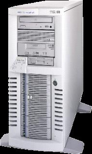
8 Router as a Computer Router components 8
9 Internetwork Operating System The operating system software used in Cisco routers is known as Cisco Internetwork Operating System (IOS). Cisco IOS is a multitasking operating system that is integrated with routing, switching, internetworking, and telecommunications functions. Although the Cisco IOS may appear to be the same on many routers, there are many different IOS images. An IOS image is a file that contains the entire IOS for that router. Cisco creates many different types of IOS images, depending upon the model of the router and the features within the IOS. Typically the more features in the IOS, the larger the IOS image, and therefore, the more flash and RAM that is required to store and load the IOS. Although some routers provide a graphical user interface (GUI), the command line interface (CLI) is a much more common method of configuring Cisco routers. The CLI is used throughout this curriculum. Upon bootup, the startup-config file in NVRAM is copied into RAM and stored as the running-config file. IOS executes the configuration commands in the running-config. Any changes entered by the network administrator are stored in the runningconfig and are immediately implemented by the IOS. 9

10 Overview - Managing Cisco IOS Software (cont) 10

11 Router as a Computer Major phases to the router boot-up process Test router hardware Power-On Self Test (POST) Execute bootstrap loader Locate & load Cisco IOS software -Locate IOS -Load IOS Locate & load startup configuration file or enter setup mode -Bootstrap program looks for configuration file 11


12 Stages of the router power-on boot sequence 12


13 Router as a Computer Major phases to the router boot-up process Step 1 and 2: Test router hardware Power-On Self Test (POST) During this self-test, the router executes diagnostics from ROM on several hardware components including the CPU, RAM, and NVRAM Execute bootstrap loader The main task of the bootstrap program is to locate the Cisco IOS and load it into RAM. Note: At this point, if you have a console connection to the router, you will begin to see output on the screen. Step 3 and 4: Locate & load Cisco IOS software -Locate IOS and Load IOS The IOS is typically stored in flash memory, but can also be stored in other places such as a TFTP server. If a full IOS image can not be located, a scaled-down version of the IOS is copied from ROM into RAM. This version of IOS is used to help diagnose any problems and can be used to load a complete version of the IOS into RAM. Note: A TFTP server is usually used as a backup server for IOS but it can also be used as a central point for storing and loading the IOS. 13
14 Router as a Computer Step 5 and 6: Locate & load startup configuration file or enter setup mode -After the IOS is loaded, the bootstrap program searches for the startup configuration file, known as startup-config, in NVRAM. This parameters including: interface addresses routing information passwords any other configurations If the startup-config, is located in NVRAM, it is copied into RAM as the running-config. The IOS loads the commands in the file, one line at a time. If the startup configuration file does not exist in NVRAM, the router may search for a TFTP server. If the router detects that it has an active link to another configured router, it sends a broadcast searching for a configuration file across the active link. You will eventually see message like the following one: %Error opening tftp:// /network-confg (Timed out) %Error opening tftp:// /cisconet.cfg (Timed out) 14
15 Router as a Computer Locate & load startup configuration file or enter setup mode Enter Setup Mode (Optional). If the startup configuration file can not be located, the router prompts the user to enter setup mode. Setup mode is a series of questions prompting the user for basic configuration information. Setup mode is not intended to be used to enter complex router configurations, and it is not commonly used by network administrators. When booting a router that does not contain a startup configuration file, you will see the following question after the IOS has been loaded: Would you like to enter the initial configuration dialog? [yes/no]: no Setup mode will not be used in this course to configure the router. When prompted to enter setup mode, always answer no. If you answer yes and enter setup mode, you can press Ctrl-C at any time to terminate the setup process. When setup mode is not used, the IOS creates a default running-config. The default running-config is a basic configuration file that includes the router interfaces, management interfaces, and certain default information. The default running-config does not contain any interface addresses, routing information, passwords, or other specific configuration information. 15
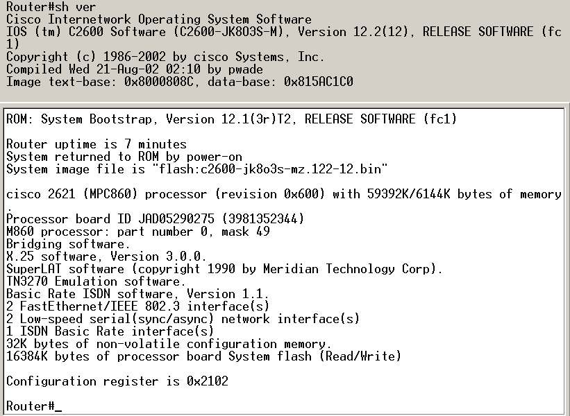
16 Router as a Computer Verify the router boot-up process: -The show version command is used to view information about the router during the bootup process. Information includes: Image name & IOS version IOS (tm) C2600 Software (C2600-I-M), Version 12.2(28), RELEASE SOFTWARE (fc5). Bootstrap version stored in ROM ROM: System Bootstrap, Version 12.1(3r)T2, RELEASE SOFTWARE (fc1) Image file name & where it was loaded from System image file is "flash:c2600-i-mz bin" show version 16
17 Router as a Computer Verify the router boot-up process: Platform model number CPU Amount of RAM Some series of routers, like the 2600, use a fraction of DRAM as packet memory. Packet memory is used for buffering packets. To determine the total amount of DRAM on the router, add both numbers. In this example, the Cisco 2621 router has 60,416 KB (kilobytes) of free DRAM used for temporarily storing the Cisco IOS and other system processes. The other 5,120 KB is dedicated for packet memory. The sum of these numbers is 65,536K, or 64 megabytes (MB) of total DRAM. show version 17
18 Router as a Computer Verify the router boot-up process: Number & type of interfaces 2 FastEthernet/IEEE interface(s) 2 Low-speed serial(sync/async) network interface(s) Amount of NVRAM 32K bytes of non-volatile configuration memory. NVRAM is used to store the startup-config file. Amount of flash 16384K bytes of processor board System flash (Read/Write) This is the amount of flash memory on the router. Flash is used to permanently store the Cisco IOS. show version 18
19 Router as a Computer Configuration register Configuration register is 0x2102 The last line of the show version command displays the current configured value of the software configuration register in hexadecimal. If there is a second value displayed in parentheses, it denotes the configuration register value that will be used during the next reload. The configuration register has several uses, including password recovery. The factory default setting for the configuration register is 0x2102. This value indicates that the router will attempt to load a Cisco IOS software image from flash memory and load the startup configuration file from NVRAM. Note: The configuration register is discussed in more detail in a later course. show version 19
20 Configuration register The order in which the router looks for system bootstrap depends on the boot field setting in the configuration register. The default configuration register setting can be changed with the global configuration mode command config-register. Use a hexadecimal number as the argument for this command. The configuration register is a 16-bit register in NVRAM. The lowest four bits of the configuration register form the boot field. To ensure that the upper 12 bits are not changed, first retrieve the current values of the configuration register using the show version command. Then use the config-register command, changing only the value of the last hexadecimal digit. 20
21 Configuration register (cont.) To enter the ROM monitor mode, set the configuration register value to 0xnnn0, where nnn represents the previous value of the non-boot field digits. This value sets the boot field bits to 0000 binary. From ROM monitor, boot the operating system manually by using the b command at the ROM monitor prompt. To configure the system to boot automatically from ROM, set the configuration register to 0xnnn1, This value sets the boot field bits to 0001 binary. To configure the system to use the boot system commands in NVRAM, set the configuration register to any value from 0xnnn2 to 0xnnnF, These values set the boot field bits to a value between 0010 and 1111 binary. Using boot system commands in NVRAM is the default. Check Configuration Register value (NVRAM) 0 = ROM Monitor mode 1 = ROM IOS 2-15 = Boot system from Flash 21
22 How a Cisco device locates and loads IOS The config-register can be Downloaded from: Demo config-register 22
23 Configuration register: 0, 1, and 2 and above 23

24 Configuration register: 2102 and


25 Configuration register Router(config)#config-register value
 If boot system commands in startup-config 1, 2 3 4 a.")
26 Stages of the router power-on boot sequence 1. ROM 1. POST 2. Bootstrap code executed 3. Check Configuration Register value (NVRAM) 0 = ROM Monitor mode 1 = ROM IOS 2-15 = Boot system from flash 2. Check for IOS boot system commands in startup-config file (NVRAM) If boot system commands in startup-config 1, a. Run boot system commands in order they appear in startup-config to locate the IOS b If boot system commands fail, use default fallback sequence to locate the IOS (Flash, TFTP, ROM) 3. Locate and load IOS, Default fallback sequence: No IOS boot system commands in startup-config a. Flash (sequential) b. TFTP server (netboot) - The router uses the configuration register value to form a filename from which to boot a default system image stored on a network server. c. ROM (partial IOS) or keep retrying TFTP depending upon router model - If no IOS located, get partial IOS version from ROM 4. Locate and load startup-config a. If startup-config found, copy to running-config b. If startup-config not found, prompt for setup-mode c. If setup-mode bypassed, create a skeleton default running-config (no startup-config) 26
27 How a Cisco device locates and loads IOS The router can use its own fallback sequence to load the software. The router looks to the boot system commands saved in NVRAM. (Tony) The router has its own default fallback sequence. This default sequence can be interrupted by using the boot system command and/or config register. The settings in the configuration register enable the following alternatives: Global configuration mode boot system commands can be specified to enter fallback sources. If NVRAM lacks boot system commands the system by default uses the Cisco IOS software in flash memory. (Tony) No boot system commands (Tony) IOS specified in the boot system does not exist If flash memory is empty, the router then attempts to use TFTP to load an IOS image from the network. 27
28 How a Cisco device locates and loads IOS 28


29 Using the boot system command The three examples show boot system entries which specify that a Cisco IOS software image will load First from flash memory, Flash memory A system image from flash memory can be loaded. Then from a network server, and Network server In case flash memory becomes corrupted, a system image can be loaded from a TFTP server. Finally from ROM: ROM If flash memory is corrupted and the network server fails to load the image, booting from ROM is the final bootstrap option in software. However, the system image in ROM is a subset of the Cisco IOS that lacks the protocols, features of the full Cisco IOS. Also, if the software has been updated, the router may have an older version stored in ROM. The command copy running-config startup-config saves the commands in NVRAM. 29
30 How a Cisco device locates and loads IOS What happen when both config-register and boot system both exist in the startup-config? Which one has the priority? 30
31 Management Ports Routers have physical connectors that are used to manage the router. These connectors are known as management ports. Unlike Ethernet and serial interfaces, management ports are not used for packet forwarding. The most common management port is the console port. The console port is used to connect a terminal, or most often a PC running terminal emulator software, to configure the router without the need for network access to that router. The console port must be used during initial configuration of the router. Another management port is the auxiliary port. Not all routers have auxiliary ports. At times the auxiliary port can be used in ways similar to a console port. It can also be used to attach a modem. Auxiliary ports will not be used in this curriculum. 31

32 Routers determine the best path Router Interface is a physical connector that enables a router to send or receive packets Each interface connects to a separate network different IP network Typically, the interfaces connect to various types of networks, which means that different types of media and connectors are required. Types of router interfaces: -Ethernet -Fastethernet -Serial -DSL -ISDN -Cable 32
33 Two major groups of Router Interfaces: LAN & WAN LAN Interfaces: such as Ethernet and FastEthernet Are used to connect router to LAN network Has a layer 2 MAC address a router Ethernet interface participates in the ARP process for that LAN. Can be assigned a Layer 3 IP address Usually consist of an RJ-45 jack When a router is connected to a switch, a straight-through cable is used. When two routers are connected directly through the Ethernet interfaces, or when a PC NIC is connected directly to a router Ethernet interface, a crossover cable is used. 33

34 Two major groups of Router Interfaces: LAN & WAN WAN Interfaces- such as serial, ISDN, and Frame Relay Are used to connect routers to external networks that interconnect LANs, usually over a larger geographical distance.. Depending on the WAN technology, a layer 2 address may be used. Uses a layer 3 IP address Similar to LAN interfaces, each WAN interface has its own IP address and subnet mask, which identifies it as a member of a specific network. The Layer 2 encapsulation can be of different types, PPP, Frame Relay, and HDLC (High- Level Data Link Control). 34
35 Two major groups of Router Interfaces: LAN & WAN The router in the figure has four interfaces. Each interface has a Layer 3 IP address and subnet mask that configures it for a different network. The Ethernet interfaces also have Layer 2 Ethernet MAC addresses. The WAN interfaces are using different Layer 2 encapsulations. Serial 0/0/0 is using HDLC Serial 0/0/1 is using PPP. Both of these serial point-to-point protocols use a broadcast address for the Layer 2 destination address when encapsulating the IP packet into a data link frame. 35
36 Routers determine the best path A router connects multiple networks. This means that it has multiple interfaces that each belong to a different IP network. When a router receives an IP packet on one interface, it determines which interface to use to forward the packet onto its destination. The interface that the router uses to forward the packet may be the network of the final destination of the packet (the network with the destination IP address of this packet), or it may be a network connected to another router that is used to reach the destination network. Routers are the network center -Routers generally have 2 connections: -WAN connection (Connection to ISP) -LAN connection 36

37 Routers determine the best path Routers examine a packet s destination IP address and determine the best path by enlisting the aid of a routing table 37
38 Routers determine the best path The primary responsibility of a router is to direct packets destined for local and remote networks by: Determining the best path to send packets Forwarding packets toward their destination The router uses its routing table to determine the best path to forward the packet. When the router receives a packet, it examines its destination IP address and searches for the best match with a network address in the router's routing table. The routing table also includes the interface to be used to forward the packet. Once a match is found, the router encapsulates the IP packet into the data link frame of the outgoing or exit interface, and the packet is then forwarded toward its destination. It is very likely that a router will receive a packet that is encapsulated in one type of data link frame, such as an Ethernet frame and when forwarding the packet, the router will encapsulate it in a different type of data link 38

39 Routers determine the best path Routers Operate at Layers 1, 2 & 3 A router makes its primary forwarding decision at Layer 3, but as we saw earlier, it participates in Layer 1 and Layer 2 processes as well. Router receives a stream of encoded bits Bits are decoded and passed to layer 2 Router de-encapsulates the frame Remaining packet passed up to layer 3 -Routing decision made at this layer by examining destination IP address Packet is then re-encapsulated & sent out outbound interface 39
40 Routers determine the best path PC1 operates at all seven layers, encapsulating the data and sending the frame out as a stream of encoded bits to R1, its default gateway. R1 receives the stream of encoded bits on its interface. The bits are decoded and passed up to Layer 2, where R1 decapsulates the frame. The router examines the destination address of the data link frame to determine if it matches the receiving interface, including a broadcast or multicast address. If there is a match with the data portion of the frame, the IP packet is passed up to Layer 3, where R1 makes its routing decision. R1 then re-encapsulates the packet into a new Layer 2 data link frame and forwards it out the outbound interface as a stream of encoded bits. R2 receives the stream of bits, and the process repeats itself. R2 decapsulates the frame and passes the data portion of the frame, the IP packet, to Layer 3 where R2 makes its routing decision. R2 then re-encapsulates the packet into a new Layer 2 data link frame and forwards it out the outbound interface as a stream of encoded bits. This process is repeated once again by router R3, which forwards the IP packet, encapsulated inside a data link frame and encoded as bits, to PC2. 40
41 Configure Devices and Apply Addresses Implementing Basic Addressing Schemes When designing a new network or mapping an existing network you must provide the following information in the form of a document: -Topology drawing that Illustrates physical connectivity Address table that provides the following information: Device name Interfaces used IP addresses Default gateway 41


42 Configure Devices and Apply Addresses 42
43 Configure Devices and Apply Addresses Basic Router Configuration A basic router configuration should contain the following: -Router name - Host name should be unique -Banner - At a minimum, banner should warn against unauthorized use -Passwords - Use strong passwords -Interface configurations Specify interface type, IP address and subnet mask. Describe purpose of interface. Issue no shutdown command. If DCE serial interface issue clock rate command. After entering in the basic configuration the following tasks should be completed -Verify basic configuration and router operations. -Save the changes on a router 43
44 Configure Devices and Apply Addresses brief review from CCNA1 Router> Router>enable Router# Router#config t Router(config)#enable secret class Router(config)#enable password cisco Router(config)#hostname R1 R1(config)# R1(config)#line console 0 R1(config-line)#password cisco R1(config-line)#login R1(config-line)#exit R1(config)#line vty 0 4 R1(config-line)#password cisco R1(config-line)#login R1(config-line)#exit 44

45 Configure Devices and Apply Addresses brief review from CCNA1 Configuring a Banner From the global configuration mode, configure the message-of-the-day (motd) banner. A delimiting character, such as a "#" is used at the beginning and at the end of the message. The delimiter allows you to configure a multiline banner, as shown here. R1(config)#banner motd # Enter TEXT message. End with the character '#'. ****************************************** WARNING!! Unauthorized Access Prohibited!! ****************************************** # Configuring an appropriate banner is part of a good security plan. At a very minimum, a banner should warn against unauthorized access. Never configure a banner that "welcomes" an unauthorized user. 45
46 Limiting Device Access Enable and Enable Secret Passwords To provide additional security, use enable password or enable secret command to establish authentication before accessing privileged EXEC (enable) mode. Always use the enable secret command, not the older enable password command, if possible. The following commands are used to set the passwords: Router(config)#enable password password Router(config)#enable secret password If no enable password or enable secret password is set, the IOS prevents privileged EXEC access from a Telnet session. Without an enable password having been set, a Telnet session would appear this way: Switch>enable % No password set Switch> 46
47 Limiting Device Access Enable and Enable Secret Passwords Example of enable password and enable secret: 47

48 Limiting Device Access Enable Secret Passwords Example of enable secret and the encryption string On the same console section enter the command enable secret class 3 times and get the 3 different encrypted strings. 48
49 Limiting Device Access VTY Password The vty lines allow access to a router via Telnet. By default, many Cisco devices support 5 VTY lines that are numbered 0 to 4. A password needs to be set for all available vty lines. The same password can be set for all connections. However, it is often desirable that a unique password be set for one line to provide a fall-back for administrative entry to the device if the other connections are in use. The following commands are used to set a password: Router(config)#line vty 0 4 Router(config-line)#password password Router(config-line)#login By default, the IOS includes the login command on the VTY lines. This prevents Telnet access to the device without first requiring authentication. If, by mistake, the no login command is set, which removes the requirement for authentication, unauthorized persons could connect to the line using Telnet. This would be a major security risk. 49
50 Encrypting Password Display Another useful command prevents passwords from showing up as plain text when viewing the configuration files. This is the service password-encryption command. This command causes the encryption of passwords to occur when a password is configured. The service password-encryption command applies weak encryption to all unencrypted passwords. This encryption does not apply to passwords as they are sent over media only in the configuration. The purpose of this command is to keep unauthorized individuals from viewing passwords in the configuration file. Once the encryption has been applied, removing the encryption service does not reverse the encryption. 50
51 Configuring router passwords (cont.) WARNING service password-encryption uses a Cisco Level 7 encryption which is very easy to decrypt. For the GetPass! software However, the enable secret <password> uses a stronger encryption method and cannot be easily hacked. and! 51

 Doesn t work")
52 Configuring router passwords (cont.) Doesn t work for enable secret! 52
53 Configure Devices and Apply Addresses R1(config)#interface Serial0/0/0 R1(config-if)#ip address R1(config-if)#description Ciruit#VBN (help desk: ) R1(config-if)#no shutdown R1(config-if)#clock rate Note: When cabling a point-to-point serial link in our lab environment, one end of the cable is marked DTE and the other end is marked DCE. The router that has the DCE end of the cable connected to its serial interface will need the additional clock rate command configured on that serial interface. This step is only necessary in a lab environment 53
54 Configure Devices and Apply Addresses the FastEthernet interface needs to be configured R1(config)#interface FastEthernet0/0 R1(config-if)#ip address R1(config-if)#description R1 LAN R1(config-if)#no shutdown 54
55 Configure Devices and Apply Addresses Each interface must belong to a different network. Although the IOS allows you to configure an IP address from the same network on two different interfaces, the router will not activate the second interface. For example, what if you attempt to configure the FastEthernet 0/1 interface on R1 with an IP address on the /24 network? FastEthernet 0/0 has already been assigned an address on that same network. you will get the following message: R1(config)#interface FastEthernet0/1 R1(config-if)#ip address overlaps with FastEthernet0/0 If there is an attempt to enable the interface with the no shutdown command, the following message will appear: R1(config-if)#no shutdown overlaps with FastEthernet0/0 FastEthernet0/1: incorrect IP address assignment The output from the show ip interface brief command shows that the second interface configured for the /24 network, FastEthernet 0/1, is still down. R1#show ip interface brief <output omitted> FastEthernet0/ YES manual administratively down down 55
56 Configure Devices and Apply Addresses Verify Basic Router Configuration -Issue the show running-config command displays the current running configuration that is stored in RAM. -Issuing the copy running-config startup-config command Save the basic router configuration -Additional commands that will enable you to further verify router configuration are: Show startup-config - Displays configuration file NVRAM Show IP route - Displays routing table Show interfaces - Displays all interface configurations Show IP int brief - Displays abbreviated interface configuration information 56
57 Configure Devices and Apply Addresses 57
58 Configure Devices and Apply Addresses 58
59 Routing Table Structure The primary function of a router is to forward a packet toward its destination network, which is the destination IP address of the packet. To do this, a router needs to search the routing information stored in its routing table. Routing Table is stored in ram and contains information: Directly connected networks - this occurs when a device is connected to another router interface Remotely connected networks - this is a network that is not directly connected to a particular router network/next hop associations - about the networks include source of information, network address & subnet mask, and Ip address of next-hop router Show ip route command is used to view a routing table 59

60 Routing Table Structure The network/exit-interface association can also represent the destination network address of the IP packet. This association occurs on the router's directly connected networks. A directly connected network is a network that is directly attached to one of the router interfaces. When a router interface is configured with an IP address and subnet mask, the interface becomes a host on that attached network. The network address and subnet mask of the interface, along with the interface type and number, are entered into the routing table as a directly connected network. When a router forwards a packet to a host, such as a web server, that host is on the same network as a router's directly connected network. A remote network is a network that is not directly connected to the router. In other words, a remote network is a network that can only be reached by sending the packet to another router. Remote networks are added to the routing table using either a dynamic routing protocol or by configuring static routes. Dynamic routes are routes to remote networks that were learned automatically by the router, using a dynamic routing protocol. Static routes are routes to networks that a network administrator manually configured. 60
61 Routing Table Structure As shown in the figure the routing table is displayed with the show ip route command. At this point, there have not been any static routes configured nor any dynamic routing protocol enabled. Therefore, the routing table for R1 only shows the router's directly connected networks. For each network listed in the routing table, the following information is included: C - The information in this column denotes the source of the route information, directly connected network, static route or a dynamic routing protocol. The C represents a directly connected route /24 - This is the network address and subnet mask of the directly connected or remote network. In this example, both entries in the routing table, /24 and /24, are directly connected networks. FastEthernet 0/0 - The information at the end of the route entry represents the exit interface and/or the IP address of the next-hop router. In this example, both FastEthernet 0/0 and Serial0/0/0 are the exit interfaces used to reach these networks. 61

62 Routing Table Structure PCs also have a routing table. In the figure, you can see the route print command output. The command reveals the configured or acquired default gateway, connected, loopback, multicast, and broadcast networks. The output from route print command will not be analyzed during this course. It is shown here to emphasize the point that all IP configured devices should have a routing table. 62
63 Routing Table Structure The following analogies may help clarify the concept of connected, static, and dynamic routes: Directly Connected Routes - To visit a neighbor, you only have to go down the street on which you already live. This path is similar to a directly-connected route because the "destination" is available directly through your "connected interface," the street. Static Routes - A train uses the same railroad tracks every time for a specified route. This path is similar to a static route because the path to the destination is always the same. Dynamic Routes - When driving a car, you can "dynamically" choose a different path based on traffic, weather, or other conditions. This path is similar to a dynamic route because you can choose a new path at many different points on your way to the destination. 63
64 Routing Table Structure Adding a connected network to the routing table -Router interfaces Each router interface is a member of a different network Activated using the no shutdown command In order for static and dynamic routes to exist in routing table you must have directly connected networks 64

65 Routing Table Structure Remote networks are added to the routing table either by configuring static routes or enabling a dynamic routing protocol. Static routes in the routing table -Includes: network address and subnet mask and IP address of next hop router or exit interface -Denoted with the code S in the routing table -Routing tables must contain directly connected networks used to connect remote networks before static or dynamic routing can be used 65

66 Routing Table Structure When to use static routes -When network only consists of a few routers Using a dynamic routing protocol in such a case does not present any substantial benefit. -Network is connected to internet only through one ISP There is no need to use a dynamic routing protocol across this link because the ISP represents the only exit point to the Internet. -Hub & spoke topology is used on a large network A hub-and-spoke topology consists of a central location (the hub) and multiple branch locations (spokes), with each spoke having only one connection to the hub. Using dynamic routing would be unnecessary because each branch has only one path to a given destination-through the central location. 66
67 Routing Table Structure Dynamic routing protocols -Are used to add remote networks to a routing table -Are used to discover networks -Are used to update and maintain routing tables Automatic network discovery -Network discovery is the ability of a routing protocol to share information about the networks that it knows about with other routers that are also using the same routing protocol. Instead of configuring static routes to remote networks on every router, a dynamic routing protocol allows the routers to automatically learn about these networks from other routers. These networks - and the best path to each network - are added to the router's routing table and denoted as a network learned by a specific dynamic routing protocol. Maintaining routing tables -Dynamic routing protocols are used to share routing information with other router & to maintain and up date their own routing table. Dynamic routing protocols not only make a best path determination to various networks, they will also determine a new best path if the initial path becomes unusable (or if the topology changes) 67
. A static route that was configured manually.")
68 Routing Table Structure R1 has learned about two remote networks: A route that dynamically used RIP In the figure, R1 has automatically learned about the /24 network from R2 through the dynamic routing protocol, RIP (Routing Information Protocol). A static route that was configured manually. This is an example of how routing tables can contain routes learned dynamically and configured statically and is not necessarily representative of the best configuration for this network. 68
69 Routing Table Structure IP routing protocols. Example of routing protocols include: RIP (Routing Information Protocol) - - CCNA IGRP (Interior Gateway Routing Protocol) - - ignore it EIGRP (Enhanced Interior Gateway Routing Protocol) - - CCNA & NP OSPF (Open Shortest Path First) - - CCNA & CCNP IS-IS (Intermediate System-to-Intermediate System) - - CCNP BGP (Border Gateway Protocol) - - CCNP RIP (versions 1 and 2), EIGRP, and OSPF are discussed in this course. EIGRP and OSPF are also explained in more detail in CCNP, along with IS-IS and BGP. IGRP is a legacy routing protocol and has been replaced by EIGRP. Both IGRP and EIGRP are Cisco proprietary routing protocols, whereas all other routing protocols listed are standard, non-proprietary protocols. 69
70 Routing Table Structure Routing Table Principles -3 principles regarding routing tables: Every router makes its decisions alone, based on the information it has in its routing table. Different routing table may contain different information A routing table can tell how to get to a destination but not how to get back (Asymmetric Routing) Routing information about a path from one network to another does not provide routing information about the reverse, or return, path. 70

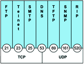
71 Router Paths and Packet Switching Internet Protocol (IP) packet format contains fields that provide information about the packet and the sending and receiving hosts Fields that are importance for CCNA students: -Version -IP header length -TTL -Precedence & type of service -Packet length -Source IP address -Destination IP address Layer 3 71

72 Router Paths and Packet Switching The Layer 2 data link frame usually contains header information with a data link source and destination address, trailer information, and the actual transmitted data. The data link source address is the Layer 2 address of the interface that sent the data link frame. MAC Layer Frame Format As a packet is forwarded from router to router, the Layer 3 source and destination IP addresses will not change; however, the Layer 2 source and destination data link addresses will change. MAC Frames are also divided into fields. They include: -Preamble Seven bytes of alternating 1s and 0s, used to synchronize signals -Start of frame delimiter 1 byte signaling the beginning of the frame -Destination MAC address 6 byte -Source MAC address 6 byte -Type/length 2 byte -Data and pad 46 to 1500 bytes of data; zeros used to pad any data packet less than 46 bytes -Frame check sequence 4 byte Layer 2 72


73 Ethernet frame fields (cont.) The original Ethernet standards defined the minimum frame size as 64-bytes and the maximum as 1518-bytes. These numbers include all bytes from the Destination MAC Address field through the Frame Check Sequence field. The Preamble and Start Frame Delimiter fields are not included when quoting the size of a frame. z The IEEE 802.3ac standard released in 1998 extended the maximum allowable frame size to 1522-bytes to allow a "VLAN tag" to be inserted into the Ethernet frame format. A Start Frame Delimiter


74 Peer to Peer Communication is really communication between the headers at each layer. Layers 2 and 3 are best effort or connectionless. Layer 4 Transport is connection oriented. The connection is in the header. 74

75 75


76 Router Paths: Best Path Whenever multiple paths to reach the same network exist, each path uses a different exit interface on the router to reach that network. The best path is selected by a routing protocol based on the value or metric it uses to determine the distance to reach a network. Metrics can be based on either a single characteristic or several characteristics of a path. Some routing protocols can base route selection on multiple metrics, combining them into a single metric. The smaller the value of the metric, the better the path. Routing protocols, such as RIP, use simple hopcount, which the number of routers between a router and the destination network. For example, a router will prefer a path that is 5 hops away over a path that is 10 hops away. Other routing protocols, such as OSPF, determine the shortest path by examining the bandwidth of the links, and using the links with the fastest bandwidth from a router to the destination network. 76
77 Router Paths and Packet Switching A Metric is a numerical value used by routing protocols help determine the best path to a destination The smaller the metric value the better the path 2 types of metrics used by routing protocols are: -Hop count - this is the number of routers a packet must travel through to get to its destination Hop count of four indicates that a packet must pass through four routers to reach its destination. If multiple paths are available to a destination, the routing protocol, such as RIP, picks the path with the least number of hops. -Bandwidth - this is the speed of a link also known as the data capacity of a link OSPF routing protocol uses bandwidth as its metric. The best path to a network is determined by the path with an accumulation of links that have the highest bandwidth values, or the fastest links. 77

78 Router Paths: Equal Cost Load Balancing You may be wondering what happens if a routing table has two or more paths with the same metric to the same destination network. When a router has multiple paths to a destination network and the value of that metric (hop count, bandwidth, etc.) is the same, this is known as an equal cost metric, and the router will perform equal cost load balancing. Equal cost metric is a condition where a router has multiple paths to the same destination that all have the same metric The router will forward packets using the multiple exit interfaces listed in the routing table. 78
79 Router Paths: Equal Cost Load Balancing To solve this dilemma, a router will use Equal Cost Load Balancing. This means the router sends packets over the multiple exit interfaces listed in the routing table. per-packet load balancing ( Process Switching) per-destination load balancing. (Fast Switching) Router(config-if)# ip route-cache Router(config-if)#no ip route-cache ping ping ping ping
80 Load balancing with RIP per-packet load balancing debug ip packet IP packet debugging is on GAD# *Mar 1 19:10:29.646: IP: tableid=0, s= (FastEthernet0/0), d= (Serial0/1), routed via RIB *Mar 1 19:10:29.646: IP: s= (FastEthernet0/0), d= (Serial0/1), g= , len 60, forward *Mar 1 19:10:30.654: IP: tableid=0, s= (FastEthernet0/0), d= (Serial0/0), routed via RIB *Mar 1 19:10:30.654: IP: s= (FastEthernet0/0), d= (Serial0/0), g= , len 60, forward *Mar 1 19:10:31.654: IP: tableid=0, s= (FastEthernet0/0), d= (Serial0/1), routed via RIB *Mar 1 19:10:31.654: IP: s= (FastEthernet0/0), d= (Serial0/1), g= , len 60, forward *Mar 1 19:10:32.218: IP: s= (FastEthernet0/0), d= , len 604, rcvd 2 *Mar 1 19:10:32.654: IP: tableid=0, s= (FastEthernet0/0), d= (Serial0/0), routed via RIB *Mar 1 19:10:32.654: IP: s= (FastEthernet0/0), d= (Serial0/0), g= , len 60, forward *Mar 1 19:10:33.654: IP: tableid=0, s= (FastEthernet0/0), d= (Serial0/1), routed via RIB *Mar 1 19:10:33.654: IP: s= (FastEthernet0/0), d= (Serial0/1), g= , len 60, forward *Mar 1 19:10:34.654: IP: tableid=0, s= (FastEthernet0/0), d= (Serial0/0), routed via RIB *Mar 1 19:10:34.654: IP: s= (FastEthernet0/0), d= (Serial0/0), g= , len 60, forward *Mar 1 19:10:35.654: IP: tableid=0, s= (FastEthernet0/0), d= (Serial0/1), routed via RIB *Mar 1 19:10:35.654: IP: s= (FastEthernet0/0), d= (Serial0/1), g= , len 60, forward *Mar 1 19:10:35.974: IP: s= (local), d= (Serial0/1), len 72, sending broad/multicast *Mar 1 19:10:36.654: IP: tableid=0, s= (FastEthernet0/0), d= (Serial0/0), routed via RIB *Mar 1 19:10:36.654: IP: s= (FastEthernet0/0), d= (Serial0/0), g= , len 60, forward RIB: Router(config-if)#no ip route-cache 80
81 Load balancing with RIP per-destination load balancing debug ip packet IP packet debugging is on GAD# *Mar 1 19:14:36.006: IP: tableid=0, s= (FastEthernet0/0), d= (Serial0/0), routed via RIB *Mar 1 19:14:36.006: IP: s= (FastEthernet0/0), d= (Serial0/0), g= , len 60, forward *Mar 1 19:14:36.026: IP: tableid=0, s= (Serial0/1), d= (FastEthernet0/0), routed via RIB *Mar 1 19:14:36.026: IP: s= (Serial0/1), d= (FastEthernet0/0), g= , len 60, forward *Mar 1 19:14:37.978: IP: s= (FastEthernet0/0), d= , len 604, rcvd 2 *Mar 1 19:14:44.122: IP: s= (FastEthernet0/0), d= , len 604, rcvd 2 *Mar 1 19:14:46.562: IP: s= (local), d= (FastEthernet0/0), len 92, sending broad/multicast *Mar 1 19:14:47.278: IP: s= (local), d= (Serial0/0), len 72, sending broad/multicast *Mar 1 19:14:50.266: IP: s= (FastEthernet0/0), d= , len 604, rcvd 2 *Mar 1 19:14:51.958: IP: s= (Serial0/1), d= , len 72, rcvd 2 *Mar 1 19:14:51.962: IP: s= (Serial0/0), d= Router(config-if)# ip route-cache RIB: 81
82 Router Paths: Un-Equal Cost Load Balancing Just in case you are wondering, a router can send packets over multiple networks even when the metric is not the same if it is using a routing protocol that has this capability. This is known as unequal cost load balancing. EIGRP (as well as IGRP) are the only routing protocols that can be configured for unequal cost load balancing. Unequal cost load balancing in EIGRP is not discussed in this course but is covered in CCNP. 82


83 Unequal Cost Load Balancing with EIGRP What is unequal cost load balancing? EIGRP Load Balancing Every routing protocol supports equal cost path load balancing. In addition to that, IGRP and EIGRP also support unequal cost path load balancing. Use the variance command to instruct the router to include routes with a metric less than n times the minimum metric route for that destination, where n is the number specified by the variance command. Example: E-C-A: 20 * 2 = 40. Therefore, E-C-A and E-B-A will be used for load balancing. router eigrp 1 network x.x.x.x variance
84 Router Paths and Packet Switching Packet forwarding involves two functions: Path determination function Switching function Path determination is a process used by a router to pick the best path to a destination One of 3 path determinations results from searching for the best path Directly connected network The destination IP address of the packet is a host address on the same network as this router's interface Remote network If the destination IP address of the packet belongs to a remote network, then the packet is forwarded to another router. No route determined the packet is discarded 84
85 Router Paths and Packet Switching Switching Function of Router is the process used by a router to switch a packet from an incoming interface to an outgoing interface on the same router. What does a router do with a packet received from one network and destined for another network? -A packet received by a router will do the following: Strips off layer 2 headers. Examines destination IP address located in Layer 3 header to find best route to destination. Re-encapsulates layer 3 packet into layer 2 frame. Forwards frame out exit interface. 85
86 Router Paths and Packet Switching As a packet travels from one networking device to another -The Source and Destination IP addresses NEVER change -The Source & Destination MAC addresses CHANGE as packet is forwarded from one router to the next. The Layer 2 data link source address represents the Layer 2 address of the outbound interface. The Layer 2 destination address represents the Layer 2 address of the next-hop router. If the next hop is the final destination device, it will be the Layer 2 address of that device. It is very likely that the packet will be encapsulated in a different type of Layer 2 frame than the one in which it was received. For example, the packet might be received by the router on a FastEthernet interface, encapsulated in an Ethernet frame, and forwarded out a serial interface encapsulated in a PPP frame. -TTL field decrement by one until a value of zero is reached at which point router discards packet (prevents packets from endlessly traversing the network) Demo 86
87 Router Paths and Packet Switching Path determination and switching function details. PC1 Wants to send something to PC 2 here is part of what happens Step 1 - PC1 encapsulates packet into a frame. Frame contains R1 s destination MAC address Ethertypes The 13th and 14th octets of an Ethernet or IEEE802.3 packet (after the preamble) consist of the "Ethernet Type" or "IEEE802.3 Length" field. The "Ethernet Type" values are managed by XEROX. Some assignments are public (see + below), others private. ebear/ethernet/type.html 87

88 Router Paths and Packet Switching Step 2 - R1 receives Ethernet frame. R1 R1 sees that destination MAC address matches its own MAC. R1 then strips off Ethernet frame. R1 Examines destination IP. R1 consults routing table looking for destination IP. After finding destination IP in routing table, R1 now looks up next hop IP address. R1 re-encapsulates IP packet with a new Ethernet frame. f the entry is not in the ARP cache, R1 sends an ARP request out its FastEthernet 0/1 interface. R2 sends back an ARP reply. R1 forwards Ethernet packet out Fa0/1 interface. 88


89 Router Paths and Packet Switching Path determination and switching function details. PC1 Wants to send something to PC 2 here is part of what happens Step 3 - Packet arrives at R2 R2 receives Ethernet frame R2 R2 sees that destination MAC address matches its own MAC R2 then strips off Ethernet frame R2 Examines destination IP R2 consults routing table looking for destination IP After finding destination IP in routing table, R2 now looks up next hop IP address R2 re-encapsulates IP packet with a new data link frame R2 forwards Ethernet packet out S0/0 interface When the interface is a point-to-point serial connection, R2 encapsulates the IP packet into the proper data link frame format used by the exit interface (HDLC, PPP, etc.). In this case, the Layer 2 encapsulation is PPP; therefore, the data link destination address is set to a broadcast. Remember, there are no MAC addresses on serial interfaces. 89


90 Router Paths and Packet Switching PC1 Wants to send something to PC 2 here is part of what happens Step 4 - Packet arrives at R3 R3 receives PPP frame R3 then strips off PPP frame R3 Examines destination IP R3 consults routing table looking for destination IP After finding destination IP in routing table, R3 is directly connected to destination via its fast Ethernet interface If the entry is not in the ARP cache, R3 sends an ARP request out its FastEthernet 0/0 interface. PC2 sends back an ARP reply with its MAC address. R3 re-encapsulates IP packet with a new Ethernet frame R3 forwards Ethernet packet out Fa0/0 interface Step 5 - IP packet arrives at PC2. Frame is decapsulated & processed by upper layer protocols. 90

91 Packet propagation and switching within a router

92 2 Packet propagation and switching within a router 92 92

93 3 Packet propagation and switching within a router
94 Packet propagation and switching within a router

95 5 Packet propagation and switching within a router 95 95

96 Packet propagation and switching within a router
97 Packet propagation and switching within a router

98 Packet propagation and switching within a router

99 Packet propagation and switching within a router
Objectives. Router as a Computer. Router components and their functions. Router components and their functions
 2007 Cisco Systems, Inc. All rights reserved. Cisco Public Objectives Introduction to Routing and Packet Forwarding Routing Protocols and Concepts Chapter 1 Identify a router as a computer with an OS and
Introduction to Routing and Packet Forwarding. Routing Protocols and Concepts Chapter 1
 Introduction to Routing and Packet Forwarding Routing Protocols and Concepts Chapter 1 1 1 Objectives Identify a router as a computer with an OS and hardware designed for the routing process. Demonstrate
Router and Routing Basics
 Router and Routing Basics Malin Bornhager Halmstad University Session Number 2002, Svenska-CNAP Halmstad University 1 Routing Protocols and Concepts CCNA2 Routing and packet forwarding Static routing Dynamic
Procedure: You can find the problem sheet on Drive D: of the lab PCs. Part 1: Router & Switch
 University of Jordan Faculty of Engineering & Technology Computer Engineering Department Computer Networks Laboratory 907528 Lab. 2 Network Devices & Packet Tracer Objectives 1. To become familiar with
Lab 5.3.5 Configuring Basic Router Settings with the Cisco IOS CLI
 Lab 5.3.5 Configuring Basic Router Settings with the Cisco IOS CLI Device Host Name Interface IP address Subnet mask R1 R1 Serial 0/0/0 (DCE) 172.17.0.1 255.255.0.0 FastEthernet 0/0 172.16.0.1 255.255.0.0
Angelos Stavrou. OF COURSE there is no Magic so lets see show things work in practice...
 Cisco Inter-network Operating System (IOS) A short guide for the NetAdmin Angelos Stavrou Let's start out at the very beginning with the question: "What is a Command?" The most important thing to understand
3.1 Connecting to a Router and Basic Configuration
 3.1 Connecting to a Router and Basic Configuration Objective This lab will focus on the ability to connect a PC to a router in order to establish a console session and observe the user interface. A console
CCNA Exploration 4.0: (II) Routing Protocols and Concepts. Chapter 1: Introduction to Routing and Packet Forwarding
 Routing Protocols and Concepts. Chapter 1: Introduction to Routing and Packet Forwarding") Http://elmaestrodelared.blogspot.com CCNA Exploration 4.0: (II) Routing Protocols and Concepts Chapter 1: Introduction to Routing and Packet Forwarding 1. If a router cannot find a valid configuration
Http://elmaestrodelared.blogspot.com CCNA Exploration 4.0: (II) Routing Protocols and Concepts Chapter 1: Introduction to Routing and Packet Forwarding 1. If a router cannot find a valid configuration
Applicazioni Telematiche
 Angelo Coiro Laboratorio Applicazioni Telematiche L emulatore Packet Tracer Packet Tracer Cisco Packet Tracer is an academic software that allows to emulate Cisco devices Packet Tracer can be used for
Lab 8.4.3a Managing Cisco IOS Images with TFTP
 Lab 8.4.3a Managing Cisco IOS Images with TFTP Host Device Name Interface IP Address Subnet Mask R1 R1 Fast Ethernet 0/0 172.17.0.1 255.255.0.0 Objectives Analyze the Cisco IOS image and router flash memory.
Note: This case study utilizes Packet Tracer. Please see the Chapter 5 Packet Tracer file located in Supplemental Materials.
 Note: This case study utilizes Packet Tracer. Please see the Chapter 5 Packet Tracer file located in Supplemental Materials. CHAPTER 5 OBJECTIVES Configure a router with an initial configuration. Use the
Lab 5.3.5 Configuring Basic Router Settings with the Cisco IOS CLI
 Lab 5.3.5 Configuring Basic Router Settings with the Cisco IOS CLI Device Host Name Interface IP Address Subnet Mask R1 R1 Serial 0/0/0 (DCE) 172.17.0.1 255.255.0.0 FastEthernet 0/0 172.16.0.1 255.255.0.0
Lab - Using IOS CLI with Switch MAC Address Tables
 Topology Addressing Table Objectives Device Interface IP Address Subnet Mask Default Gateway R1 G0/1 192.168.1.1 255.255.255.0 N/A S1 VLAN 1 192.168.1.11 255.255.255.0 192.168.1.1 S2 VLAN 1 192.168.1.12
Password Recovery Procedure for the Cisco 806, 826, 827, 828, 831, 836, 837 and 881 Series Routers
 Password Recovery Procedure for the Cisco 806, 826, 827, 828, 831, 836, 837 and 881 Series Routers Document ID: 12065 Contents Introduction Prerequisites Requirements Components Used Related Products Conventions
Configuring a Router
 CHAPTER 3 Configuring a Router This chapter provides information and commands concerning the following topics: Configuring a router, specifically: Names Passwords Interfaces MOTD banners IP host tables
Lab 5.3.9b Managing Router Configuration Files Using TFTP
 Lab 5.3.9b Managing Router Configuration Files Using TFTP Device Host Name Interface IP Address Subnet Mask R1 R1 Fast Ethernet 0/0 172.17.0.1 255.255.0.0 Objectives Download and install TFTP server software.
Password Recovery Procedure for the Cisco 3600 and 3800 Series Routers
 Password Recovery Procedure for the Cisco 3600 and 3800 Series Routers Document ID: 22189 Contents Introduction Prerequisites Requirements Components Used Related Products Conventions Step by Step Procedure
Skills Assessment Student Training Exam
 Skills Assessment Student Training Exam Topology Assessment Objectives Part 1: Initialize Devices (8 points, 5 minutes) Part 2: Configure Device Basic Settings (28 points, 30 minutes) Part 3: Configure
IP Networking. Overview. Networks Impact Daily Life. IP Networking - Part 1. How Networks Impact Daily Life. How Networks Impact Daily Life
 Overview Dipl.-Ing. Peter Schrotter Institute of Communication Networks and Satellite Communications Graz University of Technology, Austria Fundamentals of Communicating over the Network Application Layer
How To Learn Cisco Cisco Ios And Cisco Vlan
 Interconnecting Cisco Networking Devices: Accelerated Course CCNAX v2.0; 5 Days, Instructor-led Course Description Interconnecting Cisco Networking Devices: Accelerated (CCNAX) v2.0 is a 60-hour instructor-led
Lab 1.2.3 Review of Basic Router Configuration with RIP. Objective. Background / Preparation. General Configuration Tips
 Lab 1.2.3 Review of Basic Router Configuration with RIP Objective Cable and configure workstations and routers Setup IP addressing scheme using Class B networks Configure Routing Information Protocol (RIP)
CCNA 2 Chapter 5. Managing Cisco IOS Software
 1 CCNA 2 Chapter 5 Managing Cisco IOS Software The default source for Cisco IOS Software depends on the hardware platform; most commonly, though, the router looks to the configuration commands that are
CCNA 2 v5.0 Routing Protocols Final Exam Answers
 CCNA 2 v5.0 Routing Protocols Final Exam Answers 1 Refer to the exhibit. What can be concluded about network 192.168.1.0 in the R2 routing table? This network was learned through summary LSAs from an ABR.*
Lab 7.2.9 Load Balancing Across Multiple Paths
 Lab 7.2.9 Load Balancing Across Multiple Paths Objective Configure Load balance across multiple paths. Observe the load balancing process. Background/Preparation Cable a network similar to the one in the
Connect the Host to attach to Fast Ethernet switch port Fa0/2. Configure the host as shown in the topology diagram above.
 Lab 1.2.2 Capturing and Analyzing Network Traffic Host Name IP Address Fa0/0 Subnet Mask IP Address S0/0/0 Subnet Mask Default Gateway RouterA 172.17.0.1 255.255.0.0 192.168.1.1 (DCE) 255.255.255.0 N/A
"Charting the Course...
 Description "Charting the Course... Course Summary Interconnecting Cisco Networking Devices: Accelerated (CCNAX), is a course consisting of ICND1 and ICND2 content in its entirety, but with the content
100-101: Interconnecting Cisco Networking Devices Part 1 v2.0 (ICND1)
") 100-101: Interconnecting Cisco Networking Devices Part 1 v2.0 (ICND1) Course Overview This course provides students with the knowledge and skills to implement and support a small switched and routed network.
100-101: Interconnecting Cisco Networking Devices Part 1 v2.0 (ICND1) Course Overview This course provides students with the knowledge and skills to implement and support a small switched and routed network.
Lab 3 Routing Information Protocol (RIPv1) on a Cisco Router Network
 on a Cisco Router Network") Lab 3 Routing Information Protocol (RIPv1) on a Cisco Router Network CMPE 150 Fall 2005 Introduction Today you are going to be thrown into using Cisco s Internetwork Operating System (IOS) to configure
Lab 3 Routing Information Protocol (RIPv1) on a Cisco Router Network CMPE 150 Fall 2005 Introduction Today you are going to be thrown into using Cisco s Internetwork Operating System (IOS) to configure
Objectives Understand Cisco IOS system architecture components. Work with the Cisco IOS Command Line Interface (CLI) and common commands.
 and common commands.") Objectives Understand Cisco IOS system architecture components. Work with the Cisco IOS Command Line Interface (CLI) and common commands. Learn about Cisco IOS troubleshooting techniques. Understand upgrading
Objectives Understand Cisco IOS system architecture components. Work with the Cisco IOS Command Line Interface (CLI) and common commands. Learn about Cisco IOS troubleshooting techniques. Understand upgrading
Password Recovery Procedure for the Cisco Catalyst 2948G L3, 4840G, and 4908G L3 Switch Routers
 Password Recovery Procedure for the Cisco Catalyst 2948G L3, 4840G, and 4908G L3 Switch Routers Document ID: 12738 Contents Introduction Before You Begin Conventions Prerequisites Step by Step Procedure
Cisco Router Configuration Tutorial
 Cisco Router Configuration Tutorial Cisco Inter-network Operating System: Cisco IOS Modes of Operation The Cisco IOS software provides access to several different command modes. Each command mode provides
Lab: Basic Router Configuration
 Topology Diagram Addressing Table Device Interface IP Address Subnet Mask Def. Gateway R1 Fa0/0 192.168.1.1 255.255.255.0 N/A S0/0/0 192.168.2.1 255.255.255.0 N/A R2 Fa0/0 192.168.3.1 255.255.255.0 N/A
Configuring the Switch with the CLI-Based Setup Program
 APPENDIX D Configuring the Switch with the CLI-Based Setup Program This appendix provides a command-line interface (CLI)-based setup procedure for a standalone switch. For product overview information,
Lab 2 - Basic Router Configuration
 CS326 Fall 2001 Room: PAI 5.48 Name: Lab 2 - Basic Router Configuration In this lab you will learn: the various configuration modes of Cisco 2621 routers how to set up IP addresses for such routers how
Password Recovery Procedure for the Cisco 2900 Series Integrated Services Router
 Password Recovery Procedure for the Cisco 2900 Series Integrated Services Router Document ID: 112033 Contents Introduction Prerequisites Requirements Components Used Related Products Conventions Step by
Table of Contents. Cisco How Does Load Balancing Work?
 Table of Contents How Does Load Balancing Work?...1 Document ID: 5212...1 Introduction...1 Prerequisites...1 Requirements...1 Components Used...1 Conventions...1 Load Balancing...1 Per Destination and
O 10.16.1.0/27 [110/129] via 192.168.1.5, 00:00:05, Serial0/0/1
![O 10.16.1.0/27 [110/129] via 192.168.1.5, 00:00:05, Serial0/0/1](/thumbs/39/20242582.jpg "O 10.16.1.0/27 [110/129] via 192.168.1.5, 00:00:05, Serial0/0/1") 1 Which two statements are true regarding the advantages of the use of static routes? (Choose increased security reduced effort in configuring routes the administrator maintains control over routing easier
1 Which two statements are true regarding the advantages of the use of static routes? (Choose increased security reduced effort in configuring routes the administrator maintains control over routing easier
CCNA R&S: Introduction to Networks. Chapter 5: Ethernet
 CCNA R&S: Introduction to Networks Chapter 5: Ethernet 5.0.1.1 Introduction The OSI physical layer provides the means to transport the bits that make up a data link layer frame across the network media.
Lab Configuring Syslog and NTP (Instructor Version)
") (Instructor Version) Instructor Note: Red font color or Gray highlights indicate text that appears in the instructor copy only. Topology Addressing Table Objectives Device Interface IP Address Subnet Mask
(Instructor Version) Instructor Note: Red font color or Gray highlights indicate text that appears in the instructor copy only. Topology Addressing Table Objectives Device Interface IP Address Subnet Mask
Guide to TCP/IP, Third Edition. Chapter 3: Data Link and Network Layer TCP/IP Protocols
 Guide to TCP/IP, Third Edition Chapter 3: Data Link and Network Layer TCP/IP Protocols Objectives Understand the role that data link protocols, such as SLIP and PPP, play for TCP/IP Distinguish among various
Basic Software Configuration Using the Cisco IOS Command-Line Interface
 Basic Software Configuration Using the Cisco IOS Command-Line Interface This document describes how to use the Cisco IOS command-line interface (CLI) to perform a basic software configuration for your
Basic Configuration of the Cisco 12000 Series Internet Router
 CHAPTER 2 Basic Configuration of the Cisco 12000 Series Internet Router This chapter describes how to boot and configure the Cisco 12000 Series Internet Router. It discusses the following subjects: Cisco
Network Simulator Lab Study Plan
 The CCNA 640-802 Network Simulator has 300 lab exercises, organized both by type (Skill Builder, Configuration Scenario, Troubleshooting Scenario, and Subnetting Exercise) and by major topic within each
Routing Protocols and Concepts Chapter 2 Conceitos de protocolos de Encaminhamento Cap 2
 Static Routing Routing Protocols and Concepts Chapter 2 1 1 Objectives Define the general role a router plays in networks. Describe the directly connected networks, different router interfaces Examine
Cisco Certified Network Associate Exam. Operation of IP Data Networks. LAN Switching Technologies. IP addressing (IPv4 / IPv6)
") Cisco Certified Network Associate Exam Exam Number 200-120 CCNA Associated Certifications CCNA Routing and Switching Operation of IP Data Networks Operation of IP Data Networks Recognize the purpose and
Cisco Certified Network Associate Exam Exam Number 200-120 CCNA Associated Certifications CCNA Routing and Switching Operation of IP Data Networks Operation of IP Data Networks Recognize the purpose and
Chapter 2 Lab 2-2, EIGRP Load Balancing
 Chapter 2 Lab 2-2, EIGRP Load Balancing Topology Objectives Background Review a basic EIGRP configuration. Explore the EIGRP topology table. Identify successors, feasible successors, and feasible distances.
Configuring a Gateway of Last Resort Using IP Commands
 Configuring a Gateway of Last Resort Using IP Commands Document ID: 16448 Contents Introduction Prerequisites Requirements Components Used Conventions ip default gateway ip default network Flag a Default
Lab 3.1.2 Creating a Logical Network Diagram
 Lab 3.1.2 Creating a Logical Network Diagram Objectives Use router and switch commands to obtain information about an existing network. Use Cisco Network Assistant to obtain information about an existing
Cisco Certified Network Associate (CCNA) 120 Hours / 12 Months / Self-Paced WIA Fee: $2035.00
 120 Hours / 12 Months / Self-Paced WIA Fee: $2035.00") Cisco Certified Network Associate (CCNA) 120 Hours / 12 Months / Self-Paced WIA Fee: $2035.00 This fee includes the following exams: Cisco Certified Network Associate (CCNA) 100-101 ICND1 and 200-101 ICND2
Cisco Certified Network Associate (CCNA) 120 Hours / 12 Months / Self-Paced WIA Fee: $2035.00 This fee includes the following exams: Cisco Certified Network Associate (CCNA) 100-101 ICND1 and 200-101 ICND2
Building a Network in GNS3
 Building a Network in GNS3 In this tutorial, you will create a network in GNS3 between two routers, and each router will have one host connected to it. The ultimate goal is to route data between network
IP Addressing and Subnetting. 2002, Cisco Systems, Inc. All rights reserved.
 IP Addressing and Subnetting 2002, Cisco Systems, Inc. All rights reserved. 1 Objectives Upon completion, you will be able to: Discuss the Types of Network Addressing Explain the Form of an IP Address
CHAPTER 3 STATIC ROUTING
 CHAPTER 3 STATIC ROUTING This chapter addresses the end-to-end delivery service of IP and explains how IP routers and hosts handle IP datagrams. The first section discusses how datagrams are forwarded
Chapter 8 Lab B: Configuring a Remote Access VPN Server and Client
 Chapter 8 Lab B: Configuring a Remote Access VPN Server and Client Topology Note: ISR G2 devices have Gigabit Ethernet interfaces instead of FastEthernet Interfaces. All contents are Copyright 1992 2012
Interconnecting Cisco Network Devices 1 Course, Class Outline
 www.etidaho.com (208) 327-0768 Interconnecting Cisco Network Devices 1 Course, Class Outline 5 Days Interconnecting Cisco Networking Devices, Part 1 (ICND1) v2.0 is a five-day, instructorled training course
Router Lab Reference Guide
 Router Lab Reference Guide 1 PURPOSE AND GOALS The routing lab allows testing different IP-related protocols and solutions in a close to live environment. You can learn how to configure Cisco routers and
Configuring Switch Ports and VLAN Interfaces for the Cisco ASA 5505 Adaptive Security Appliance
 CHAPTER 5 Configuring Switch Ports and VLAN Interfaces for the Cisco ASA 5505 Adaptive Security Appliance This chapter describes how to configure the switch ports and VLAN interfaces of the ASA 5505 adaptive
ROM Monitor. Entering the ROM Monitor APPENDIX
 APPENDIX B This appendix describes the Cisco router ROM monitor (also called the bootstrap program). The ROM monitor firmware runs when the router is powered up or reset. The firmware helps to initialize
GLBP - Gateway Load Balancing Protocol
 GLBP - Gateway Load Balancing Protocol Gateway Load Balancing Protocol (GLBP) protects data traffic from a failed router or circuit, like Hot Standby Router Protocol (HSRP) and Virtual Router Redundancy
Lab 5.3.8 Configuring PAT with SDM and Static NAT using Cisco IOS Commands
 Lab 5.3.8 Configuring PAT with SDM and Static NAT using Cisco IOS Commands Device Host Name Interface IP Address Subnet Mask R1 CustomerRouter Serial 0/0/0 (DTE) 209.165.200.225 255.255.255.224 Fast Ethernet
Lab 4.2.4 Advanced Telnet Operations
 Lab 4.2.4 Advanced Telnet Operations Objective Use the telnet command to remotely access other routers. Verify that the application layer between the source and the destination is working properly. Suspend
How To Configure InterVLAN Routing on Layer 3 Switches
 How To Configure InterVLAN Routing on Layer 3 Switches Document ID: 41860 Contents Introduction Prerequisites Requirements Components Used Conventions Configure InterVLAN Routing Task Step by Step Instructions
How to Configure Cisco 2600 Routers
 Helsinki University of Technology Department of Communications and Networking How to Configure Cisco 2600 Routers Juha Järvinen 10.6.2004 Juha.Jarvinen@netlab.hut.fi Modified by Zhong Yunqiu 7.8.2008 Table
- Basic Router Security -
 1 Enable Passwords - Basic Router Security - The enable password protects a router s Privileged mode. This password can be set or changed from Global Configuration mode: Router(config)# enable password
WANs and Routers. M.Sc. Aleksandra Kanevce M.Sc. Aleksandra Bogojeska
 WANs and Routers M.Sc. Aleksandra Kanevce M.Sc. Aleksandra Bogojeska 1 Introduction to WANs A WAN is a data communications network that spans a large geographic area such as a state, province, or country.
- Advanced IOS Functions -
 1 The Configuration Register - Advanced IOS Functions - The configuration register (config-register) is a hexadecimal value that controls various aspects of how a router boots, including: Baud Rate Boot
Welcome to Todd Lammle s CCNA Bootcamp
 Welcome to Todd Lammle s CCNA Bootcamp Todd Lammle Cisco Authorized CCNA Bootcamps are now available, delivered by CCSI instructor, and popular Sybex author Todd Lammle. Todd Lammle CCNA Training Boot
Cisco CCNA Optional Semester 4 Labs Wide Area Networking LAB 1 T1 TSU WAN LINK OVERVIEW - Instructor Guide (Estimated time: 30 minutes)
") CNAP @ VCC 1 of 8 LAB 1 T1 TSU WAN LINK OVERVIEW - Instructor Guide (Estimated time: 30 minutes) Objectives: Understand the function of a T1 Service Unit (TSU) in network telecommunications Connect routers
CNAP @ VCC 1 of 8 LAB 1 T1 TSU WAN LINK OVERVIEW - Instructor Guide (Estimated time: 30 minutes) Objectives: Understand the function of a T1 Service Unit (TSU) in network telecommunications Connect routers
CCT vs. CCENT Skill Set Comparison
 Operation of IP Data Networks Recognize the purpose and functions of various network devices such as Routers, Switches, Bridges and Hubs Select the components required to meet a given network specification
SSVP SIP School VoIP Professional Certification
 SSVP SIP School VoIP Professional Certification Exam Objectives The SSVP exam is designed to test your skills and knowledge on the basics of Networking and Voice over IP. Everything that you need to cover
Configuring a Leased Line
 CHAPTER 4 Configuring a Leased Line The configuration in this chapter describes how to configure a Cisco 1700 router for IP and IPX over a synchronous serial line. Before You Begin The configuration in
Lab 7.2.9 Load Balancing Across Multiple Paths Instructor Version 2500
 Lab 7.2.9 Load Balancing Across Multiple Paths Instructor Version 2500 Objective onfigure Load balance across multiple paths. Observe the load balancing process. Background/Preparation able a network similar
Lab 8.4.3b Managing Cisco IOS images with ROMMON and TFTP
 Lab 8.4.3b Managing Cisco IOS images with ROMMON and TFTP Host Device Name Interface IP Address Subnet Mask R1 R1 Fast Ethernet 0/0 172.17.0.1 255.255.0.0 Objectives Analyze the Cisco IOS image and router
Brocade to Cisco Comparisons
 1 2 3 Console cables - The console cables are not interchangeable between Brocade and Cisco. Each vendor provides their console cable with each manageable unit it sells. Passwords - Neither Cisco or Brocade
Interconnecting Cisco Networking Devices, Part 1 (ICND1) v3.0
 v3.0") Interconnecting Cisco Networking Devices, Part 1 (ICND1) v3.0 COURSE OVERVIEW: Interconnecting Cisco Networking Devices, Part 1 (ICND1) v3.0 is a five-day, instructor-led training course that teaches learners
Interconnecting Cisco Networking Devices, Part 1 (ICND1) v3.0 COURSE OVERVIEW: Interconnecting Cisco Networking Devices, Part 1 (ICND1) v3.0 is a five-day, instructor-led training course that teaches learners
PT Activity: Configure Cisco Routers for Syslog, NTP, and SSH Operations
 PT Activity: Configure Cisco Routers for Syslog, NTP, and SSH Operations Instructor Version Topology Diagram Addressing Table Device Interface IP Address Subnet Mask Default Gateway Switch Port R1 FA0/1
Objectives. Background. Required Resources. CCNA Security
 Chapter 8 Lab B, Configuring a Remote Access VPN Server and Client Topology IP Addressing Table Device Interface IP Address Subnet Mask Default Gateway Switch Port R1 FA0/1 192.168.1.1 255.255.255.0 N/A
Configure ISDN Backup and VPN Connection
 Case Study 2 Configure ISDN Backup and VPN Connection Cisco Networking Academy Program CCNP 2: Remote Access v3.1 Objectives In this case study, the following concepts are covered: AAA authentication Multipoint
Packet Tracer 3 Lab VLSM 2 Solution
 Packet Tracer 3 Lab VLSM 2 Solution Objective Create a simulated network topology using Packet Tracer Design an IP addressing scheme using a Class B subnetwork address and VLSM Apply IP addresses to the
Cisco 12 CCNA Certification
 Cisco 12 CCNA Certification Application for Board Authorization of Courses District: Chilliwack School District 33 Developed by: John Murtha Date: May7, 2004 School: Sardis Secondary Principal: Bob Patterson
INTERCONNECTING CISCO NETWORK DEVICES PART 1 V2.0 (ICND 1)
") INTERCONNECTING CISCO NETWORK DEVICES PART 1 V2.0 (ICND 1) COURSE OVERVIEW: Interconnecting Cisco Networking Devices, Part 1 (ICND1) v2.0 is a five-day, instructor-led training course that teaches learners
INTERCONNECTING CISCO NETWORK DEVICES PART 1 V2.0 (ICND 1) COURSE OVERVIEW: Interconnecting Cisco Networking Devices, Part 1 (ICND1) v2.0 is a five-day, instructor-led training course that teaches learners
Lab 2.3.2 Configuring OSPF with Loopback Addresses
 Lab 2.3.2 Configuring OSPF with Loopback Addresses Objective Configure routers with a Class C IP addressing scheme. Observe the election process for designated routers (DR) and backup designated routers
Lab 5.3.7 Configuring DHCP with SDM and the Cisco IOS CLI
 Lab 5.3.7 Configuring DHCP with SDM and the Cisco IOS CLI Device Host Name Interface IP Address Subnet Mask R1 Customer Serial 0/0/1 (DTE) 209.165.200.225 255.255.255.224 Fast Ethernet 0/0 192.168.1.1
How To Configure A Cisco Router With A Cio Router
 CHAPTER 1 This chapter provides procedures for configuring the basic parameters of your Cisco router, including global parameter settings, routing protocols, interfaces, and command-line access. It also
Introduction about cisco company and its products (network devices) Tell about cisco offered courses and its salary benefits (ccna ccnp ccie )
 Tell about cisco offered courses and its salary benefits (ccna ccnp ccie )") CCNA Introduction about cisco company and its products (network devices) Tell about cisco offered courses and its salary benefits (ccna ccnp ccie ) Inform about ccna its basic course of networking Emergence
CCNA Introduction about cisco company and its products (network devices) Tell about cisco offered courses and its salary benefits (ccna ccnp ccie ) Inform about ccna its basic course of networking Emergence
Introduction to Dynamic Routing Protocols
 CHAPTER 3 Introduction to Dynamic Routing Protocols Objectives Upon completion of this chapter, you should be able to answer the following questions: Can you describe the role of dynamic routing protocols
Lab 1.4.1 Introductory Lab 1 - Getting Started and Building Start.txt
 Lab 1.4.1 Introductory Lab 1 - Getting Started and Building Start.txt Objective This lab may introduce new CCNP lab equipment and certain IOS features. This introductory activity also describes how to
CCNA Exploration 4.0.5.0 Routing Protocols and Concepts Student Lab Manual
 4.0.5.0 Routing Protocols and Concepts Student Lab Manual This document is exclusive property of Cisco Systems, Inc. Permission is granted to print and copy this document for non-commercial distribution
BRI to PRI Connection Using Data Over Voice
 BRI to PRI Connection Using Data Over Voice Document ID: 14962 Contents Introduction Prerequisites Requirements Conventions Background Information Configure Network Diagram Configurations Verify Troubleshoot
LAB MANUAL for Computer Network
 LAB MANUAL for Computer Network CSE-310 F Computer Network Lab L T P - - 3 Class Work : 25 Marks Exam : 25 MARKS Total : 50 Marks This course provides students with hands on training regarding the design,
Lab 4.1.4 Creating a Network Map using CDP Instructor Version 2500
 Lab 4.1.4 Creating a Network Map using CDP Instructor Version 2500 Objective Use Cisco Discovery Protocol (CDP) commands to get information about neighboring network devices. Background/Preparation CDP
Zarząd (7 osób) F inanse (13 osób) M arketing (7 osób) S przedaż (16 osób) K adry (15 osób)
 F inanse (13 osób) M arketing (7 osób) S przedaż (16 osób) K adry (15 osób)") QUESTION NO: 8 David, your TestKing trainee, asks you about basic characteristics of switches and hubs for network connectivity. What should you tell him? A. Switches take less time to process frames than
QUESTION NO: 8 David, your TestKing trainee, asks you about basic characteristics of switches and hubs for network connectivity. What should you tell him? A. Switches take less time to process frames than
LAB THREE STATIC ROUTING
 LAB THREE STATIC ROUTING In this lab you will work with four different network topologies. The topology for Parts 1-4 is shown in Figure 3.1. These parts address router configuration on Linux PCs and a
http://computernetworkingnotes.com/ccna-study-guide/cisco-ios-naming-convention-explainedwith-examples.html
 IOS is the most critical part of any cisco device. We should always keep a backup copy of IOS to deal with any unwanted situation. In this article I will explain the backup and restore process of IOS in
Networking Test 4 Study Guide
 Networking Test 4 Study Guide True/False Indicate whether the statement is true or false. 1. IPX/SPX is considered the protocol suite of the Internet, and it is the most widely used protocol suite in LANs.
Cisco Configuration Professional Quick Start Guide
 Cisco Configuration Professional Quick Start Guide April 29, 2011 This document explains how to start using Cisco Configuration Professional Express (Cisco CP Express) and Cisco Configuration Professional
The Purpose and Use of the Configuration Register on All Cisco Routers
 The Purpose and Use of the Configuration Register on All Cisco Routers Document ID: 50421 Contents Introduction Prerequisites Requirements Components Used Conventions The Purpose of the Configuration Register
Lab 1.5.1 Introductory Lab 1 Getting Started and Building Start.txt
 Lab 1.5.1 Introductory Lab 1 Getting Started and Building Start.txt Objective This lab will introduce to the student the CCNP lab equipment and certain IOS features that might be new. This introductory
Upon completion of this chapter, you should be able to answer the following questions:
 CHAPTER 1 WANs and Routers Objectives Upon completion of this chapter, you should be able to answer the following questions: Which four groups of industry professionals create the rules and standards that
AN ANALYTICAL STUDY OF INTERNET AND INTRANET CONNECTIONS AND CONFIGURATIONS IN ISP
 AN ANALYTICAL STUDY OF INTERNET AND INTRANET CONNECTIONS AND CONFIGURATIONS IN ISP Mst. Najnin Sultana, Abu Jafar Md. Masud Karim Daffodil International University, Dhaka, Bangladesh E-mail: apesnajnin@yahoo.com