Optimizing TV Transmitting Antennas for ATSC-M/H Mobile TV. B i l l
|
|
|
- Vivian French
- 3 years ago
- Views:
Transcription


1 Optimizing TV Transmitting Antennas for ATSC-M/H Mobile TV B i l l
2 An under the Radome look at antenna design to optimize ATSC- We will take a look at: M/H transmission Azimuth Pattern Polarization Differences How the elevation pattern is built and customized Why adding a vertical component to the antenna is needed How the vertical component is formed and controlled Elliptical versus Circular Polarization Four antenna system designs for DTV / ATSC-M/H Summary
3 Azimuth Pattern Differences In many cases there are distinct differences in a slot antenna s horizontal and vertical azimuth pattern. Vertical and horizontal polarized currents flow at different values around the pylon and directional parastitics hence different patterns form. Omnioid Cardioid Omni-directional = slot location
4 Azimuth Pattern B Rotated Degrees --- H Pol --- V Pol Here is a comparison plot of the horizontal and vertical azimuth patterns of the popular Omnioid pattern. This pattern uses a single slot and no parastitics. In the vertical plane there is much less current flowing around the back side of the pylon, hence little field is produced. H Pol azimuth gain is 1.7, V Pol is 3.1.
5 V Pol Azimuth H Pol Azimuth A wide cardioid on channel 18. Pylon diameter to parastitic length were optimized to keep the H and V Pol azimuths close. H Pol azimuth gain is 2.1, V Pol azimuth gain is 1.87.
6 H - Pol V - Pol Here is a medium Cardioid pattern with an H Pol azimuth gain of 2.42 and a vertical azimuth gain of 3.2.
7 Peanut Pattern Rotated 13 Degrees --- H Pol --- V Pol Here is the azimuth plot comparison of a peanut pattern Antenna. The H Pol azimuth gain is 2.2 and the V Pol azimuth gain is 2.45.
8 - H Pol -V Pol Azimuth Pattern O3 Rotated Degrees Three slot around Omni-directional azimuth pattern. With a given pylon diameter as frequency goes up the vertical pattern will scallop more.
9 How Elevation Patterns Are Created Let s look at how null fill and beam tilt are formed on a 1 bay slot antenna. We will use a specially spaced low RFR design for this demonstration Example Bays No Beam Tilt No Null Fill Gain = (1.92 db) Array Electrical Length is 342 degrees
10 1..9 Example Bays.25 Degree Beam Tilt 3.3% First Null Fill Gain = (1.89 db) Array Electrical Length is 338 degrees The upper two slots have had their spacing reduced by 2 degrees. The array now has.25 degrees of electrical beam tilt and the first null has been raised from.% of peak field to 3.3%. The second, and third nulls have been increased slightly from.%. The elevation gain has dropped slightly to and the electrical length of the array has dropped by 4 degrees to 338 degrees.
11 1. Example Bays.5 Degree Beam Tilt 6.7% First Null Fill Gain = (1.74 db) Array Electrical Length is 3324 degrees The upper two slots have had their spacing reduced by 48 degrees. The array now has.5 degrees of electrical beam tilt and the first null has been raised from 3.3% of peak field to 6.7%. The second through fifth nulls have been increased slightly from.%. The elevation gain has dropped slightly to and the electrical length of the array has dropped by 96 degrees to 3324 degrees.
12 1..9 Example Bays.7 Degree Beam Tilt 1% First Null Fill Gain = (1.48 db) Array Electrical Length is 3268 degrees The upper two slots have had their spacing reduced by 76 degrees. The array now has.7 degrees of electrical beam tilt and the first null has been raised from 6.7% of peak field to 1.%. The second through fifth nulls are increasing nicely The elevation gain has dropped to and the electrical length of the array has dropped by an additional 56 degrees to 3268 degrees.
13 Adding a Vertical Component With ATSC-M/H in action your viewers are on the move in dynamic reception environments. The antenna in most cases is not in a horizontal position The main reason for the desirability of circularly- or elliptically-polarized transmit antennas is because, with a linearly-polarized transmit antenna, as the television signals propagate from the transmitting to the receiving site, the polarization can be rotated due to the influence of external magnetic fields from sources such as the earth itself or large metallic structures like buildings that may have a magnetic moment. This is referred to as Faraday Rotation. If the signals arrive cross-polarized from the transmitting to the receive antenna, the attenuation can be severe enough to cause the loss of signal at the television receiver. Adding a vertical component to your signal can greatly enhance reception of your station. How do we add the vertical component?
14 Review: How a slot antenna works The slot antenna is a TEM-Mode coaxial structure. Coupling structures inside the pylon will distort and couple to the fields in this coaxial antenna, causing a voltage to be applied directly across each of the slots in the antenna. This voltage alternates from plus to minus and back again at the channel frequency of operation. The length of the slots are adjusted so that the oscillating electric fields that develop across the gap that the slot creates will launch a radiating system of fields, propagating away from the antenna. 1λ ~.8 λ If the coaxial pylon antenna is oriented vertically, with the slots cut in the outer conductor oriented vertically as well, the electric fields across these slots will be oriented horizontally.

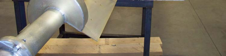
15 The E/P or C/P slot antenna Polarizer elements are mounted on either side of the slot. The polarizers are about 1/8 λ each and launch a vertically polarized electromagnetic field ¼ of a cycle or 9 degrees later than the horizontal field in quadrature. When axial the ratio between the two fields is equal we have Circular Polarization (C/P). When the horizontal field is stronger than the vertical we have elliptical polarization. For ATSC-M/H a 7/3 to 5/5 H to V ratio is ideal Channel 13 C/P Antenna


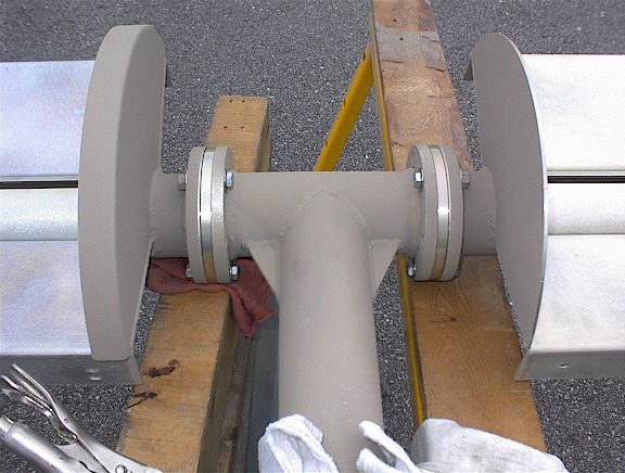
16 Did you know: Depending on the bay count and relative frequency versus element spacing, a Batwing style antenna can produce up to a 1% vertical component. Pictured here is a scaled to frequency channel 11 VHF batwing antenna.
17 Let s Look At Four Sample Projects Project 1 A 48 kw DTV station in a city of 35, transmitting from an office building in the center of the city. 95% of the population is within 1 miles of the transmitter and the topography is flat. Antenna is 4 AGL. Most ATSC-M/H users would be within 3 miles of the transmitter. Project 2 A 15 kw LD station in a city of 2,, transmitting from a mountain ridge that s 18 feet higher than the valley. The core population runs from the edge of the mountain to about 6 miles from the transmitter. Project 3 a 4 kw DTV that is transmitting from a mountain at 7,7 feet AMSL. The core of the city 7.3 miles away is a big tourist draw and would make up the bulk of ATSC-M/H users. Project 4 Super-Duper World in Orlando wants to run ATSC-M/H up I-75 to the Georgia line in an distributed network. A number of 25 to 35 foot cell towers are available. Each station would be a 15 kw LD facility. Fairly flat land along the highway.
18 Project 1 a 48 kw DTV station at 4 AGL! There are two large universities within 3 miles prime mobile TV viewers You have a 5 kw transmitter and a tower on top a building in downtown. 95% of your viewers are within 1 miles the other 5% are outside that area. Antenna Pattern? Omnioid or Omni?! Remember the different patterns of an Omnioid versus Omni-directional? Omni please! Vertical Component? a 7/3 power split would provide an excellent vertical component. So your vertical ERP would be 3/7 * 48 kw or 2.57 kw. Your total ERP in both planes would be kw. You have a 5 kw transmitter feeding a very short run of line kw/5 kw comes up to a minimum antenna vertical gain of A minimum of a 14 bay antenna would be needed!
19 Here is the 14 bay elevation pattern with.5 degrees of beam tilt we are going to use. We wanted fairly uniform field down to about -2 degrees to blanket the downtown area Main beam touchdown at 22 miles from tower This point is 2 miles from the tower This point is 12 from the tower This point is 4 from the tower Project 1

20 Project 1 Here is the same 14 bay antenna with the elevation plot shown in a Polar format, This is a low RFR specially spaced antenna.
21 Project 2 A 15 kw LD station on a ridge A 15 kw LD station is on a ridge 18 feet from the valley floor. The close in population is 16 degrees below the horizon the distant population is up to 3 miles out at the horizon. Half of the population is within 1 miles. A broad cardioid pattern works well since the H and V Pol patterns are close. V Pol Azimuth H Pol Azimuth We have 2.5 kw TPO available so a fairly low gain antenna will work
22 Bay SFN.8 BT -- 1 Bay SFN 1. BT 5.24 kw ERP ( db) kw ERP 759 Watts ERP (+13.6 db) Watts ERP Here are two elevation patterns to look at One is a 1 bay, the second is a 12 bay. The distant points in the valley where viewers are is between. and -.7 degrees. The downtown core is at -4. degrees, the close in population starts at -16. degrees The 1 bay is the winner!
23 Project 3 A 4 kw DTV Station From a 75 foot high mountain the station needs to cover the valley which has population starting at 4.8 miles from the transmitter site to 17.7 miles away at the end of the valley. The core of the city (7.3 miles away) is a large tourist draw, is about a mile in diameter and would be the largest concentration of ATSC-M/H users. The transmitter also feeds more than 2 translators and numerous CATV headends within 1 miles. Where are the viewers? Close in 4.8 miles away depression angle -7.5 degrees Downtown Core 7.3 miles away depression angle degrees Far Valley 17.7 miles away depression angle degrees Out of city CATV s and Translators up to 1 miles away -.5 to degrees Solve These Problems That The Station Has! A dual cabinet 4 kw transmitter that only likes being a 25 kw one! High Tower rental costs - $$ by the foot! Antenna on public land RFR needs to be contained
24 Project 3 Using an 18 bay low RFR antenna This point is miles from the transmitter This point is 7.3 miles From the transmitter This point is 4.8 miles from the transmitter
25 Project 4 Super Duper World SFN s Provide ATSC-M/H along I-75 to the thousands of cars that use the highway each day. Each site will be a 15 kw LD site with the antenna 25 to 3 feet AGL. A 1.5 kw transmitter is planned for each site. A wide peanut pattern with a horizontal azimuth gain of 2.2 has been filed on for each site. Peanut Pattern Rotated 13 Degrees --- H Pol --- V Pol Because of the way the parastitics are placed, the horizontal and vertical azimuth patterns are close. This is perfect for maximizing the signal along the highway
26 Project 4 The elevation pattern The 1 bay pattern we created earlier is perfect for the job. The field does not go to zero until it hits -4 degrees This point is 245 from tower This point is 29 from the tower With.7 degrees of beam tilt the main beam hits the ground 4 miles from the tower the field value at the radio horizon is still 98.2%
27 Summary Plan your directional pattern carefully to ensure the vertical coverage is where it needs to be. The cost/benefit ratio maxes out with a 7/3 V/H split. Urban areas are a better case for C/P. The E/P or C/P antenna may increase the tower loading over a H Pol only model due to radome size. Lower gain antennas provide wider main beams and allow fuller control null fill.


28 Thank You! For More Information: George Harris Bill Ammons Lewiston Maine our hometown
700 and 800 MHz Band Slot Antennas
 Low Group Delay, Wide Bandwidth UHF Slot Antennas Omni-directional and Directional Patterns Available Low RFR Models Available Top or Side Mount Models Horizontal, Elliptical, or Circular Polarization
Selecting Receiving Antennas for Radio Tracking
 Selecting Receiving Antennas for Radio Tracking Larry B Kuechle, Advanced Telemetry Systems, Inc. Isanti, Minnesota 55040 lkuechle@atstrack.com The receiving antenna is an integral part of any radio location
Antenna Deployment Technical Brief
 ProCurve Networking Antenna Deployment Technical Brief Introduction... 2 Antenna types... 2 Omni directional antennas... 2 Directional antennas... 2 Diversity antennas... 3 High gain directional antennas...
Antenna Glossary Before we talk about specific antennas, there are a few common terms that must be defined and explained:
 Antenna Basics Introduction Antennas are a very important component of communication systems. By definition, an antenna is a device used to transform an RF signal, traveling on a conductor, into an electromagnetic
5. ANTENNA TYPES. Figure 5. The vertical dipole and its electromagnetic equivalent, the vertical monopole
 Antennas can be classified in several ways. One way is the frequency band of operation. Others include physical structure and electrical/electromagnetic design. The antennas commonly used for LMR both
Avaya WLAN 9100 External Antennas for use with the WAO-9122 Access Point
 Avaya WLAN 9100 External Antennas for use with the WAO-9122 Access Point Overview To optimize the overall performance of a WLAN in an outdoor deployment it is important to understand how to maximize coverage
Antenna Properties and their impact on Wireless System Performance. Dr. Steven R. Best. Cushcraft Corporation 48 Perimeter Road Manchester, NH 03013
 Antenna Properties and their impact on Wireless System Performance Dr. Steven R. Best Cushcraft Corporation 48 Perimeter Road Manchester, NH 03013 Phone (603) 627-7877 FAX: (603) 627-1764 Email: sbest@cushcraft.com
Antenna Patterns and Their Meaning
 Antenna Patterns and Their Meaning Much can be learned about how an antenna performs from its patterns. This paper describes many of the common antenna parameters that can be understood from the patterns.
Antenna Measurement 1 Antenna Ranges antenna range
 Antenna Measurement 1 Antenna Ranges An antenna range is a facility where antenna radiation characteristics are measured. An antenna range includes the following typical components: 1. A substantial space
Just a Dipole. Gary Wescom N0GW July 16, 2007
 Just a Dipole Gary Wescom N0GW July 16, 2007 Often we will hear people describing their antennas as just a dipole. After all, a coax cable fed, half wavelength dipole is one of the simplest antennas to
Antenna Basic Concepts
 ANTENNA An antenna is a device to transmit and/or receive electromagnetic waves. Electromagnetic waves are often referred to as radio waves. Most antennas are resonant devices, which operate efficiently
Hang Em High: Options for antennas, masts and towers
 Hang Em High: Options for antennas, masts and towers Antennas play an important role in radio broadcasting. The antenna is the piece of equipment which gets your signal out to the audience you want to
470-806 MHz. Band IV/V (UHF) TV Slot Antennas. www.rfsworld.com. RD Series BROADCAST & HF ANTENNAS
 TV Slot Antennas. www.rfsworld.com. RD Series BROADCAST & HF ANTENNAS") RD Series The RD Series of broadband UHF antennas are lightweight in design, yet rugged in approach. They solve the critical question of using a single UHF antenna for multichannel Analog and DTV Broadcasting.
RD Series The RD Series of broadband UHF antennas are lightweight in design, yet rugged in approach. They solve the critical question of using a single UHF antenna for multichannel Analog and DTV Broadcasting.
Broadband Slotted Coaxial Broadcast Antenna Technology
 Broadband Slotted Coaxial Broadcast Antenna Technology Summary Slotted coaxial antennas have many advantages over traditional broadband panel antennas including much smaller size and wind load, higher
Antenna Diversity in Wireless Local Area Network Devices
 Antenna Diversity in Wireless Local Area Network Devices Frank M. Caimi, Ph.D. Kerry L. Greer Jason M. Hendler January 2002 Introduction Antenna diversity has been used in wireless communication systems
A Novel GPS Survey Antenna
 A Novel GPS Survey Antenna Waldemar Kunysz, NovAtel Inc. BIOGRAPHY Waldemar Kunysz obtained a BSEE from the Technical University of Nova Scotia in 1989. From 1991 to 1995 he worked on phased array antennas
PROTECTION OF THE BROADCASTING SERVICE FROM BROADCASTING SATELLITE SERVICE TRANSMISSIONS IN THE BAND 620 790 MHz
 Electronic Communications Committee (ECC) within the European Conference of Postal and Telecommunications Administrations (CEPT) PROTECTION OF THE BROADCASTING SERVICE FROM BROADCASTING SATELLITE SERVICE
This Antenna Basics reference guide includes basic information about antenna types, how antennas work, gain, and some installation examples.
 Antenna Basics This Antenna Basics reference guide includes basic information about antenna types, how antennas work, gain, and some installation examples. What Do Antennas Do? Antennas transmit radio
Selecting a Transmission Line for Your Broadcast System
 Selecting a Transmission Line for Your Broadcast System Introduction This Bulletin presents the procedures broadcasters need for calculating attenuation and power handling parameters to properly design
Rec. ITU-R F.699-5 1 RECOMMENDATION ITU-R F.699-5 *
 Rec. ITU-R F.699-5 1 RECOMMENATION ITU-R F.699-5 * REFERENCE RAIATION PATTERNS FOR LINE-OF-SIGHT RAIO-RELAY SYSTEM ANTENNAS FOR USE IN COORINATION STUIES AN INTERFERENCE ASSESSMENT IN THE FREQUENCY RANGE
Omni Antenna vs. Directional Antenna
 Omni Antenna vs. Directional Antenna Document ID: 82068 Contents Introduction Prerequisites Requirements Components Used Conventions Basic Definitions and Antenna Concepts Indoor Effects Omni Antenna Pros
Antenna Trainer EAN. www.edibon.com. Technical Teaching Equipment INTRODUCTION
 Antenna Trainer EAN Technical Teaching Equipment Products Products range Units 3.-Communications INTRODUCTION Antennas are the main element of aerial communications. They are the transition between a transmission
The VHF / UHF «Eggbeater» Antenna ~ Revisited ~
 The VHF / UHF «Eggbeater» Antenna ~ Revisited ~ ON6WG / F5VIF A new simple way to build the Eggbeater Antenna Introduction Previous designs described in «VHF / UHF «Eggbeater» Antenna ~ Part 1» and «VHF
REPORT ITU-R BO.2029. Broadcasting-satellite service earth station antenna pattern measurements and related analyses
 Rep. ITU-R BO.229 1 REPORT ITU-R BO.229 Broadcasting-satellite service earth station antenna pattern measurements and related analyses (Question ITU-R 93/11) (22) 1 Introduction Recommendation ITU-R BO.1443
Understanding the Electrical Performance of Category Cables
 Understanding the Electrical Performance of Category Cables By: Mike Levesque, Mike Karg & Himmeler Themistocle Obsessed with cable solutions. Understanding the Electrical Performance of Category Cables
A comparison of radio direction-finding technologies. Paul Denisowski, Applications Engineer Rohde & Schwarz
 A comparison of radio direction-finding technologies Paul Denisowski, Applications Engineer Rohde & Schwarz Topics General introduction to radiolocation Manual DF techniques Doppler DF Time difference
AN INTRODUCTION TO TELEMETRY PART 1: TELEMETRY BASICS
 AN INTRODUCTION TO TELEMETRY PART 1: TELEMETRY BASICS Telemetry is defined as the sensing and measuring of information at some remote location and then transmitting that information to a central or host
'' EGGBEATER '' ANTENNA VHF/UHF ~ PART 2
 '' EGGBEATER '' ANTENNA VHF/UHF ~ PART 2 ON6WG / F5VIF Summary Note : In Part 1, Fig 1 shows a maximum gain of 6.45 dbi. Several design attempts were made using slightly different configurations ( i.e.
EE302 Lesson 14: Antennas
 EE302 Lesson 14: Antennas Loaded antennas /4 antennas are desirable because their impedance is purely resistive. At low frequencies, full /4 antennas are sometime impractical (especially in mobile applications).
RADIATION PATTERNS. The half-power (-3 db) beamwidth is a measure of the directivity of the antenna.
 beamwidth is a measure of the directivity of the antenna.") RADIATION PATTERNS The radiation pattern is a graphical depiction of the relative field strength transmitted from or received by the antenna. Antenna radiation patterns are taken at one frequency, one
RADIATION PATTERNS The radiation pattern is a graphical depiction of the relative field strength transmitted from or received by the antenna. Antenna radiation patterns are taken at one frequency, one
ISS Minimalist Antenna
 ISS Minimalist Antenna The purpose of this project was to develop an antenna suggestion that would allow for a simple to duplicate, affordable antenna solution for reasonable access to signals transmitted
MICROWAVE ANTENNA PATTERN WITH DIFFERENT PARAMETER EVALUATION IN MOBILE ENVIRONMENT
 www.arpapress.com/volumes/vol9issue1/ijrras_9_1_07.pdf MICROWAVE ANTENNA PATTERN WITH DIFFERENT PARAMETER EVALUATION IN MOBILE ENVIRONMENT 1,* D.S. Ramkiran, 2 A.RamaKrishna, 1 Ch.Radhika & 1 B.T.P.Madhav
Amplifier for Small Magnetic and Electric Wideband Receiving Antennas (model AAA-1B)
") Amplifier for Small Magnetic and Electric Wideband Receiving Antennas (model AAA-1B) 1. Description and Specifications Contents 1.1 Description 1.2 1.2 Specifications 1.3 1.3 Tested parameters in production
Amplifier for Small Magnetic and Electric Wideband Receiving Antennas (model AAA-1B) 1. Description and Specifications Contents 1.1 Description 1.2 1.2 Specifications 1.3 1.3 Tested parameters in production
Pillbox Antenna for 5.6 GHz Band Dragoslav Dobričić, YU1AW dragan@antennex.com
 Pillbox Antenna for 5.6 GHz Band Dragoslav Dobričić, YU1AW dragan@antennex.com Introduction The pillbox or cheese antenna is made of two parallel plates which are connected to the narrow strip of parabolic
Internal GPS Active Patch Antenna Application Note
 Internal GPS Active Patch Antenna Application Note APN-13-8-002/A Page 1 of 14 1. BASICS 2. APPLICATIONS 3. SIZE 4. SHAPE 5. GROUND PLANE 6. IMPEDANCE 7. BANDWIDTH 8. VSWR 9. LINK BUDGET 10. GAIN 11. NOISE
ELEMENTS OF CABLE TELEVISION
 1 ELEMENTS OF CABLE TELEVISION Introduction Cable television, from its inception, developed in western countries into two separate systems called Master Antenna Television (MATV) and Community Cable Television
Cellular Wireless Antennas
 Cellular Wireless Antennas A Technical Brief GarrettCom Inc., November 2010 Overview The Cellular Wireless Antenna Technical brief is provided to assist with the design and deployment of the DX940 Cellular
New Antenna Concepts for Digital TV. UHF Antenna Panels for Circular, Elliptical or Slant Polarisation
 New Antenna Concepts for Digital TV UHF Antenna Panels for Circular, Elliptical or Slant Polarisation Basics about the polarisation of electromagnetic waves The polarisation of an electromagnetic wave
Printed Dipole Array Fed with Parallel Stripline for Ku-band Applications
 Printed Dipole Array Fed with Parallel Stripline for Ku-band Applications M. Dogan 1, 3,K. Özsoy 1, 2, and I.Tekin 1, 1 Electronics Engineering, Sabanci University, Istanbul, Turkey 2 Vestek Electronic
Technician Licensing Class
 Technician Licensing Class Antennas Presented by Amateur Radio Technician Class Element 2 Course Presentation ELEMENT 2 SUB-ELEMENTS (Groupings) About Ham Radio Call Signs Control Mind the Rules Tech Frequencies
Designing Log Periodic Antennas
 Designing Log Periodic Antennas By Glen Dash, Ampyx LLC, GlenDash at alum.mit.edu Copyright 2000, 2005 Ampyx LLC Lightweight and precise, the log periodic has become a favorite among EMC engineers. In
Planning Terrestrial Radio Networks
 Planning Terrestrial Radio Networks Lab Exercise Manual IK2500 - Radio Communication, Basic Course September 23, 2008 Short Summary The scope of this lab is to help students to develop basic skills in
BASICS OF C & Ku BAND TRANSMISSIONS & LNBs
 Page 1 of 6 BASICS OF C & Ku BAND TRANSMISSIONS & LNBs A satellite broadcasts a few watts of microwave signals from the geostationary orbit 36,000 kilometers above the earth. The transmissions are also
Applications in EMC testing. Outline. Antennas for EMC Testing. Terminology
 Antennas for EMC Testing Zhong Chen ETS-Lindgren 1301 Arrow Point Drive Cedar Park, TX 78613 Zhong.Chen@ets-lindgren.com Outline EMC Terms and Definitions Typical EMC Antennas Calibration of EMC Antennas
Antennas & Propagation. CS 6710 Spring 2010 Rajmohan Rajaraman
 Antennas & Propagation CS 6710 Spring 2010 Rajmohan Rajaraman Introduction An antenna is an electrical conductor or system of conductors o Transmission - radiates electromagnetic energy into space o Reception
This paper will explain some of the more important factors on how UTP wires work; specifically it will cover the following:
 UTP Technology In the late 1970s, unshielded twisted pair (UTP) cabling originated in the computer industry as a means of transmitting digital data over computer networks. This cable was designed to be
ww.rainfo.net Chippewa Valley Astronomical Society star party introduces the Little Bitty Telescope tm Version 2 and LBT Experiment No.
 See you at the WaterHoletm Volume 2001 Issue I ww.rainfo.net Chippewa Valley Astronomical Society star party introduces the Little Bitty Telescope tm Version 2 and LBT Experiment No. 1 The fall star party
Experiment 8: Undriven & Driven RLC Circuits
 Experiment 8: Undriven & Driven RLC Circuits Answer these questions on a separate sheet of paper and turn them in before the lab 1. RLC Circuits Consider the circuit at left, consisting of an AC function
Performance Specifications
 Performance Specifications Channels: VHF: 2-13 UHF: 14-69 Output Impedance: 75 ohms Dimensions (with elements): 9 1 /8"H* x 13 1 /2"W x 16 1 /2"D *Height with dipoles fully extended 42 Amplifier Gain:
Physics 41, Winter 1998 Lab 1 - The Current Balance. Theory
 Physics 41, Winter 1998 Lab 1 - The Current Balance Theory Consider a point at a perpendicular distance d from a long straight wire carrying a current I as shown in figure 1. If the wire is very long compared
2/20/2009 3 Transmission Lines and Waveguides.doc 1/3. and Waveguides. Transmission Line A two conductor structure that can support a TEM wave.
 2/20/2009 3 Transmission Lines and Waveguides.doc 1/3 Chapter 3 Transmission Lines and Waveguides First, some definitions: Transmission Line A two conductor structure that can support a TEM wave. Waveguide
cellularbooster.com THINGS YOU MUST KNOW BEFORE YOU 7BUY AND INSTALL A CELLULAR BOOSTER
 cellularbooster.com THINGS YOU MUST KNOW BEFORE YOU 7BUY AND INSTALL A CELLULAR BOOSTER We have created this ebook for people who need some help understanding cellular phone boosters. As most people are
ABHELSINKI UNIVERSITY OF TECHNOLOGY
 Basic of Propagation Theory S-72.333 Physical Layer Methods in Wireless Communication Systems Fabio Belloni Helsinki University of Technology Signal Processing Laboratory fbelloni@wooster.hut.fi 23 November
EMC STANDARDS STANDARDS AND STANDARD MAKING BODIES. International. International Electrotechnical Commission (IEC) http://www.iec.
 http://www.iec.") EMC STANDARDS The EMC standards that a particular electronic product must meet depend on the product application (commercial or military) and the country in which the product is to be used. These EMC regulatory
EMC STANDARDS The EMC standards that a particular electronic product must meet depend on the product application (commercial or military) and the country in which the product is to be used. These EMC regulatory
102 26-m Antenna Subnet Telecommunications Interfaces
 DSMS Telecommunications Link Design Handbook 26-m Antenna Subnet Telecommunications Interfaces Effective November 30, 2000 Document Owner: Approved by: Released by: [Signature on file in TMOD Library]
BSA Technical Information
 BSA Technical Information Electrical Isolation of Co-Located Horizontally and Vertically Stacked Antennas Introduction: Service providers are facing rapidly increasing pressure from zoning boards to co-locate
ACCESS CHARGE A fee charged subscribers or other telephone companies by a local exchange carrier for the use of its local exchange networks.
 Glossary of Telecommunications Terms (Source: Federal Communications Commission) ACCESS CHARGE A fee charged subscribers or other telephone companies by a local exchange carrier for the use of its local
FOR EXISTING 254-FOOT COMMUNICATIONS TOWER 16700 Skyline Drive La Habra Heights California
 MASTER PLAN FOR EXISTING 254-FOOT COMMUNICATIONS TOWER 16700 Skyline Drive La Habra Heights California PROPERTY OWNER: Coast Community College District 1370 Adams Avenue Costa Mesa, CA 92626 Attn: Richard
Digital Audio and Video Broadcasting Antenna Components and Systems
 Digital Audio and Video Broadcasting Antenna Components and Systems KATHREIN, founded in 1919 in Rosenheim, Germany, is an international enterprise active in antenna and communications technology. For
RECOMMENDATION ITU-R F.1113. (Question ITU-R 157/9) b) that systems using this mode of propagation are already in service for burst data transmission,
 b) that systems using this mode of propagation are already in service for burst data transmission,") Rec. ITU-R F.1113 1 RECOMMENDATION ITU-R F.1113 RADIO SYSTEMS EMPLOYING METEOR-BURST PROPAGATION (Question ITU-R 157/9) (1994) Rec. ITU-R F.1113 The ITU Radiocommunication Assembly, considering a) that
Rec. ITU-R F.1113 1 RECOMMENDATION ITU-R F.1113 RADIO SYSTEMS EMPLOYING METEOR-BURST PROPAGATION (Question ITU-R 157/9) (1994) Rec. ITU-R F.1113 The ITU Radiocommunication Assembly, considering a) that
Yerkes Summer Institute 2002
 Before we begin our investigations into radio waves you should review the following material on your trip up to Yerkes. For some of you this will be a refresher, but others may want to spend more time
Embedded FM/TV Antenna System
 1 Embedded FM/TV Antenna System Final Report Prepared for By January 21, 2011 2 Table of Contents 1 Introduction... 5 2 Technical Specification... 6 3 Prototype Antenna... 7 4 FASTROAD Active module fabrication...
MIMO Antenna Systems in WinProp
 MIMO Antenna Systems in WinProp AWE Communications GmbH Otto-Lilienthal-Str. 36 D-71034 Böblingen mail@awe-communications.com Issue Date Changes V1.0 Nov. 2010 First version of document V2.0 Feb. 2011
Understanding SWR by Example
 Understanding SWR by Example Take the mystery and mystique out of standing wave ratio. Darrin Walraven, K5DVW It sometimes seems that one of the most mysterious creatures in the world of Amateur Radio
Important HP Media Center PC Updates
 Important HP Media Center PC Updates Your system uses Microsoft Windows XP Media Center Edition 2005. Before starting the system and using the Media Center setup wizard, please read this updated information
CABLES CABLES. Application note. Link Budget
 CABLES CABLES radiating Link Budget 3. 1. LINK BUDGET The basic elements to calculate a link budget can be illustrated by considering the example shown in Figure 4. It involves a GSM 900 radio coverage
Digital Television Broadcasting Systems Testing in Brazil
 Digital Television Broadcasting Systems Testing in Brazil Kiev, Ukraine - 13-15 November 2000 Interregional Seminar on the Transition from SECAM to Digital TV Broadcasting Renato Maroja - maroja@cpqd.com.br
Amplification of the Radiation from Two Collocated Cellular System Antennas by the Ground Wave of an AM Broadcast Station
 Amplification of the Radiation from Two Collocated Cellular System Antennas by the Ground Wave of an AM Broadcast Station Dr. Bill P. Curry EMSciTek Consulting Co., W101 McCarron Road Glen Ellyn, IL 60137,
Flexible PCB Antenna with Cable Integration Application Note Version 2
 Flexible PCB Antenna with Cable Integration Application Note Version 2 CONTENTS 1. BASICS 2. APPLICATIONS 3. SIZE 4. SHAPE 5. GROUND PLANE SIZE 6. IMPEDANCE 7. BANDWIDTH 8. VSWR 9. GAIN 10. EFFICIENCY
Antennas 101 The Basics. Ward Silver NØAX
 Antennas 101 The Basics Ward Silver NØAX The Basics - 1 Antennas radiate (or receive) because electrons are accelerated (or are caused to accelerate) in the antenna s elements Radio or electromagnetic
AM TRANSMITTERS & RECEIVERS
 Reading 30 Ron Bertrand VK2DQ http://www.radioelectronicschool.com AM TRANSMITTERS & RECEIVERS Revision: our definition of amplitude modulation. Amplitude modulation is when the modulating audio is combined
Two primary advantages of radars: all-weather and day /night imaging
 Lecture 0 Principles of active remote sensing: Radars. Objectives: 1. Radar basics. Main types of radars.. Basic antenna parameters. Required reading: G: 8.1, p.401-40 dditional/advanced reading: Online
Insertion Devices Lecture 4 Permanent Magnet Undulators. Jim Clarke ASTeC Daresbury Laboratory
 Insertion Devices Lecture 4 Permanent Magnet Undulators Jim Clarke ASTeC Daresbury Laboratory Introduction to Lecture 4 So far we have discussed at length what the properties of SR are, when it is generated,
RF EXPOSURE LIMITS AND TESTING REQUIREMENTS
 RF EXPOSURE LIMITS AND TESTING REQUIREMENTS Jay Moulton Vice President March 12, 2013 1 OVERVIEW Specific Absorption Rate (SAR) and Maximum Permissible Exposure (MPE) Standards and Limits Evaluation Methods
RFS - One Stop Shop of Innovation
 RFS - One Stop Shop of Innovation Prasanna Meemaduma www.rfsworld.com June 2015 1 RFS One Stop Shop of Innovation RFS Product Lines WIRELESS INFRASTRUCTURE SOLUTIONS Base Station Antennas & RF Conditioning
Efficient 2 meter Disguise Antenna Made From a TV Satellite Dish
 Efficient 2 meter Disguise Antenna Made From a TV Satellite Dish This horizontal slot antenna, cut into the reflector of a TV dish, is both the master of disguise and high in performance. By John Portune
Magnetic Fields and Their Effects
 Name Date Time to Complete h m Partner Course/ Section / Grade Magnetic Fields and Their Effects This experiment is intended to give you some hands-on experience with the effects of, and in some cases
Sensor and Simulation Notes. Note 479. October 2003. A Dual-Polarity Impulse Radiating Antenna
 Sensor and Simulation Notes Note 479 October 2003 A Dual-Polarity Impulse Radiating Antenna Leland H. Bowen and Everett G. Farr Farr Research, Inc. Dean I. Lawry Air Force Research Laboratory, Directed
LRS - Application Form PRESIDENT OF THE OFFICE OF ELECTRONIC COMMUNICATIONS
 Date...... LRS (company's stamp) ref. sign:... PRESIDENT OF THE OFFICE OF ELECTRONIC COMMUNICATIONS Issue No.: The application concerns the station: APPLICATION for a license on usage of radio devices
Wideband Code Division Multiple Access (W CDMA) Tutorial
 Tutorial") Wideband Code Division Multiple Access (W CDMA) Tutorial Definition Wideband code division multiple access (W CDMA) is a CDMA channel that is four times wider than the current channels that are typically
Wideband Code Division Multiple Access (W CDMA) Tutorial Definition Wideband code division multiple access (W CDMA) is a CDMA channel that is four times wider than the current channels that are typically
Common Mode and Differential Mode Noise Filtering
 Summary Introduction This application note gives a practical explanation of differential mode and common mode noise along with the traditional filtering approaches. In addition, an alternative method of
Isolation between antennas of IMT base stations in the land mobile service
 Report ITU-R M.44 (11/011) Isolation between antennas of IMT base stations in the land mobile service M Series Mobile, radiodetermination, amateur and related satellite services ii Rep. ITU-R M.44 Foreword
ASTRA 3B HORN ANTENNA DESIGN
 ASTRA 3B HORN ANTENNA DESIGN Jorge Teniente and Carlos del-río Grupo de Antenas, Universidad Pública de Navarra, Campus Arrosadía s/n, 31006 Spain, Email: jorge.teniente@unavarra.es, carlos@unavarra.es
Modeling an 80/40/20M Fan Dipole for DX
 Modeling an 80/40/20M Fan Dipole for DX New Station New Antennas! Installation and SWR Response Where is the DX? How do these Dipoles Play? (EZNEC) What about Terrain? HFTA and Terrain The effect on these
STACKING, PHASING and MATCHING YAGIS
 STACKING, PHASING and MATCHING YAGIS This is a synopsis of a talk presented to the Sydney VHF DX GROUP on Tuesday March 16th 1999 by Gordon McDonald VK2ZAB. QUESTIONS When the stacking of Yagis is being
The purposes of this experiment are to test Faraday's Law qualitatively and to test Lenz's Law.
 260 17-1 I. THEORY EXPERIMENT 17 QUALITATIVE STUDY OF INDUCED EMF Along the extended central axis of a bar magnet, the magnetic field vector B r, on the side nearer the North pole, points away from this
Electromagnetic (EM) waves. Electric and Magnetic Fields. L 30 Electricity and Magnetism [7] James Clerk Maxwell (1831-1879)
![Electromagnetic (EM) waves. Electric and Magnetic Fields. L 30 Electricity and Magnetism [7] James Clerk Maxwell (1831-1879)](/thumbs/40/20813653.jpg "Electromagnetic (EM) waves. Electric and Magnetic Fields. L 30 Electricity and Magnetism [7] James Clerk Maxwell (1831-1879)") L 30 Electricity and Magnetism [7] ELECTROMAGNETIC WAVES Faraday laid the groundwork with his discovery of electromagnetic induction Maxwell added the last piece of the puzzle Heinrich Hertz made the experimental
L 30 Electricity and Magnetism [7] ELECTROMAGNETIC WAVES Faraday laid the groundwork with his discovery of electromagnetic induction Maxwell added the last piece of the puzzle Heinrich Hertz made the experimental
Mobile Phones: Jargon Explained
 Mobile Phones: Jargon Explained 2G 3G Aerial Second Generation Mobile Phone System. See GSM See Third Generation Mobile Phone System. Device designed to radiate and receive electromagnetic energy. Antenna
Understanding Range for RF Devices
 Understanding Range for RF Devices October 2012 White Paper Understanding how environmental factors can affect range is one of the key aspects to deploying a radio frequency (RF) solution. This paper will
Physics 202 Problems - Week 8 Worked Problems Chapter 25: 7, 23, 36, 62, 72
 Physics 202 Problems - Week 8 Worked Problems Chapter 25: 7, 23, 36, 62, 72 Problem 25.7) A light beam traveling in the negative z direction has a magnetic field B = (2.32 10 9 T )ˆx + ( 4.02 10 9 T )ŷ
UHF DIPOLE ANTENNA AS-2810C/SRC
 TECHNICAL MANUAL OPERATION AND INSTALLATION INSTRUCTIONS UHF DIPOLE ANTENNA AS-2810C/SRC Valcom Limited 175 Southgate Drive, P.O.Box 603, Guelph, Ontario, Canada N1H 6L3 Tel: 519-824-3220 Fax: 519-824-3411
Interferometers. OBJECTIVES To examine the operation of several kinds of interferometers. d sin = n (1)
") Interferometers The true worth of an experimenter consists in his pursuing not only what he seeks in his experiment, but also what he did not seek. Claude Bernard (1813-1878) OBJECTIVES To examine the
Interferometers The true worth of an experimenter consists in his pursuing not only what he seeks in his experiment, but also what he did not seek. Claude Bernard (1813-1878) OBJECTIVES To examine the
Transmission Line and Back Loaded Horn Physics
 Introduction By Martin J. King, 3/29/3 Copyright 23 by Martin J. King. All Rights Reserved. In order to differentiate between a transmission line and a back loaded horn, it is really important to understand
T = 1 f. Phase. Measure of relative position in time within a single period of a signal For a periodic signal f(t), phase is fractional part t p
, phase is fractional part t p") Data Transmission Concepts and terminology Transmission terminology Transmission from transmitter to receiver goes over some transmission medium using electromagnetic waves Guided media. Waves are guided
Data Transmission Concepts and terminology Transmission terminology Transmission from transmitter to receiver goes over some transmission medium using electromagnetic waves Guided media. Waves are guided
INTERFERENCE OF SOUND WAVES
 1/2016 Sound 1/8 INTERFERENCE OF SOUND WAVES PURPOSE: To measure the wavelength, frequency, and propagation speed of ultrasonic sound waves and to observe interference phenomena with ultrasonic sound waves.
Why is Passive Intermodulation Important?
 Precision Products for Demanding Applications Low PIM Products for Distributed Antenna Systems and Wireless Infrastructure Low PIM Coaxial Cable Assemblies Plenum Rated, Low PIM, Low Loss Coaxial Cable
Owners Manual For The PackTenna Mini
 Owners Manual For The PackTenna Mini By Nick Garner N3WG and George Zafiropoulos KJ6VU Quickstart With The 9:1 Random Wire Version You can identify this version because it has a yellow shrink wrap on the
Installation Instructions
 Installation Instructions Attention! These installation instructions are intended for use by qualified professional technicians due to the complexity of the installation and compliance to national/local
WSR - Weather Surveillance Radar
 1 of 7 Radar by Paul Sirvatka College of DuPage Meteorology WSR - Weather Surveillance Radar It was learned during World War II that electromagnetic radiation could be sent out, bounced off an object and
What is a Horizontal Curve?
 Paul Deutsch What is a Horizontal Curve? Provides a transition between two tangent lengths of roadway. PI PC PT PC (Point of Curvature at beginning of curve) PI (Point of Intersection of tangents) PT (Point