Assemble Instruction of Geeetech Acrylic Prusa I3 Pro & pro B
|
|
|
- Ethelbert Stone
- 7 years ago
- Views:
Transcription

1 Assemble Instruction of Geeetech Acrylic Prusa I3 Pro & pro B
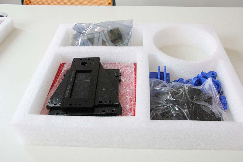
2 Notice:. This kit contains tiny parts; please keep them away from kids under 3.. This building instruction applies to both Geeetech Acrylic Prusa I3 pro and pro B. 3. Some pictures of the printed part may be a bit different from those in your package, no worries, they work the same, and the way to assemble is similar. 4. Building and operating 3D printer involves electricity, so all necessary precautions should be taken and adhered to. 5. Building a 3d printer requires a certain amount of handling ability and basic knowledge of working principle of 3D printer. 6. Be patient, please. If you have any problems assembling, please contact us, we will try our best to help you. Unfold the box and check the package Unfold the package and take all the parts out to check the condition of the items. As you can see, all the parts are packed very carefully.


3 All the acrylic plate has been etched with part ID and the plate is covered with a sheet of kraft paper, you need to tear them off.

4
5 Tips: Shenzhen GETECH CO.,LTD. Before assembly, you are advised to put all the parts, especially the screws and nuts in order, which will save you a lot of time looking for the required parts.. The part ID is corresponding to the number labeled on the bag of every part. Some parts may not have label, you can refer to the pictures on the package list. Assemble Y axis. Assemble the rods of a Y axis Step. Assemble the threaded rods. Required parts Required number Part ID M0 threaded rod NO.5 Y plate connecting plate NO.A4 M8 spring washer 6 NO.8 M0 washer 8 NO.9 M0 nut 8 NO. Thread the nuts and washers into the two M0 threaded rods separately. The order should be: ) Thread the acrylic fender (Y plate connecting plate) in the middle. ) Thread the M0 washer > M8 spring washer >M0 nut > M0 nut > M0 washer on the left

6 3) Thread them0 washer < M8 spring washer < M0 nut < M0 nut< M8 spring washer < M0 washer on the right Step. Assemble the smooth rods Required parts Required number Part ID M8 smooth rod NO.3 LM8UU Linear bearings 4 NO.39 Slide bearings on each smooth rod. Before you slide the bearings please make sure they are clean.
7 .. Attach the front and rear Acrylic support plates of the rods. Required parts Required number Part ID Acrylic plate( front) NO. A9, A 0 Acrylic plate( rear) NO. A, A M0 washer 4 NO.9 M0 nut 4 NO. Step. Slide the rods into the acrylic plate; adjust the length so that the smooth rods fit snugly between the front and rear piece. Step. Screw up the rods and plate with M0 nut and M0 washer.

8 * Tips: the Y-axis must be a rectangle, that is the rods on both side should be parallel, so is the front and back plate. Otherwise it will cause obstruction for the belt later. You can use a Digital Caliper to measure.. Assemble the Y idler Required parts Required number Part ID 64ZZ Ball bearing NO.38 bearing holder NO.66 M3 x 0 screw NO.7 M3 wing nut NO.5 M4 x5 screw NO.35

9 M4 lock nut Shenzhen GETECH CO.,LTD NO.4 Step. Thread the M3 x 0 screw through the bearing holder. Step. Put the M4 x5 screw through the holes with the two 64ZZ bearings in between. Lock the other end with a M4 lock nut.

10 Step3. Mount the assembled bearing holder onto the front support plates. And screw it with a wing nut. *Please leave enough room for the belt between the ball bearing and the screw.

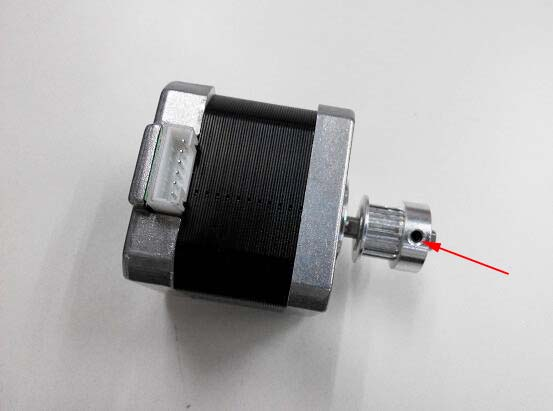
11 .3 Mount the Y motor Required parts Required number Part ID Y motor fix plate NO. A3 Stepper motor NO.75 pulley NO.43 M3 x screw 3 NO.5 M3 x 6 screw NO.6 M3 square nut NO.6 Step. Mount the pulley on the motor shaft, one of the screws should be screwed on the cross section of the shaft. Do not screw too tight to turn smoothly.

12 Step. Insert the motor block into the slot; you may need to use a little strength to do this. But be careful in case the Acrylic broke down. Then screw the motor on the block plate with 3 M3 x screws and fix the block plate with M3 x 6 screws and M3 square nut.

13 .4 Build the printing platform Required parts Required number Part ID Y platform support NO.A5 Y bearing block 4 NO.A6 Y belt mount NO.67 Zip tie 4 NO.54 M3 x 0 screw NO.4 M3 x 0 screw 8 NO.7 M3 nut 8 NO. Step. Mount the belt mount on the bottom side of the platform with M3 x 0

14 screws. Shenzhen GETECH CO.,LTD Step. Mount the 4 bearing blocks on the platform with M3 x 0 screws on the same side with the belt-mount. Screw with M3 nuts.


15 Step3. Get the build platform plate zip-tied to the 4 linear bearings of Y- Axis. *The belt-mount and the fenders are under the platform.
16 .5 Mount the Y axis belt. Required parts Required number Part ID Timing belt NO.4 M3 x 0 screw NO.4 M3 washer NO.7 Step. Drill a hole on one end of the belt(the hole can be as the diameter of the M3 screw, leave enough margin ) Step. Fix the belt on one side of the belt -mount with a M3 x 0 screw and washer. Step3. Thread the belt around the pulley on the motor and the Y idler. Step4. Drill a hole on the other end of the belt and fix it on the belt -mount with a M3 x 0 screw and M3 washer. *Tips:. Before you drill your second hole, make sure to pull belt tightly to make sure to fin d proper placement of hole for a tight belt, if it is too loose, it will hinder the move of the print platform.. Loosen the Y idler wing nut when tightening belt onto the Y belt mount [No. 67] in order to make securing the belt to the block easier. Be sure to tighten wing nut fully o nce done.

17 3 Assemble Y - Z axis Required parts Required number Part ID X-Z frame NO.A M3 x 0 screw 4 NO.7 M3 nut 4 NO. Step. Held upright the main frame is after the acrylic fender washers on the threaded rods. Here you can use the A panel as a reference to measure the distance A and A (the rear plate).


18 Step. Screw up the main frame to the acrylic fender with M3 x 0 screws. Step3. Screw up the M0 screw on the threaded rod of Y-axis. You can see the

19 finished picture. Shenzhen GETECH CO.,LTD 4 Mount the fan Required parts Required number Part ID Fan NO.70 M3 x 30 screw 4 NO.8 M3 locknut 4 NO.3 Fix the fan on the right side of the frame with 4 M3 x 30 screw and locknut. Mind the direction of the wires. (Please pay attention to the fan not others)

20 5 Assemble the right and left side panel Required parts Required number Part ID Acrylic left frame NO.A Acrylic right frame NO.A3 M3 x 6 screw 8 NO.6 M3 square nut 8 NO.6 Step. Screw up the X-Z frame and the side panel then connect the rear part of the Y
 6. Assemble the Z-axis bottom mount Required parts Required number Part ID Z Motor fixed plate NO.A4, A5 Z Motor support plate 4 NO.A6, A7 M3 x 6 screw 0 NO.")
21 axis and the side panel together. You may need to adjust the distance of the X-Z frame to the rear plate. All you need here is M3 x 6 screws and M3 square nuts. 6 Assemble the Z axis (the vertical axis) 6. Assemble the Z-axis bottom mount Required parts Required number Part ID Z Motor fixed plate NO.A4, A5 Z Motor support plate 4 NO.A6, A7 M3 x 6 screw 0 NO.6 M3 square nut 0 NO.6 Step. It would be easier to mount the A4/A5 to A6 and A7 first, and then mount the

22 assembled part to A. Shenzhen GETECH CO.,LTD Step.Screw up the acrylic plates with M3 x 6 screws and M3 square nuts. *The right and left bottom mount are different; the left one has a mount for the Z end stop. Please look at the following picture.

23 6. Assemble the Z motors Required parts Required number Part ID Stepper Motor NO.75 M3 x screw 8 NO.5

24 Step.Thread the wires of the motors through the holes
 7. Assemble the smooth rods.")
25 Step. Screw up the motors with 4 M3 x screws. Do the same with the other Z motor. 7 Assemble the X axis (the horizontal axis) 7. Assemble the smooth rods. Required parts Required number Part ID 370mm smooth rod NO.

26 LM8UU linear bearing Shenzhen GETECH CO.,LTD NO.40 Slide the two bearings into the two rods respectively. 7. Assemble the X-Axis Idler Required parts Required number Part ID 64ZZ Ball bearing NO.38 Bearing holder NO. 66 M3 X30 screw NO.8 M4 X5 screw NO.35 M4 locknut NO.4 Step. Put the screw through the Y bearing holder.
27 Step. Thread the M4 x 5 screw through the holder with the 64ZZ bearings in between. Lock the other end of a M4 nut.

28 7.3 Assemble the X-Axis end Shenzhen GETECH CO.,LTD Required parts Required number Part ID X-axis left end X-axis right end LM8UU linear bearing M3 wing nut NO.P NO.P NO.40 NO.5 M3 x 6 screw NO. 6 M3 nut NO. Step. Mount the assembled idler into the right X-axis end. Here, you can insert the linear bearing into the end. Step. Lock it up with a wing nut and insert a linear bearing into the slot.

29 Step3. Insert another linear bearing into the slot of left end. Then lock the bearing with M3x 6 screw and nut. Do the same to the right end.

30 7.4 Assemble the X-axis rods and both ends Required parts Required number Part ID Brass nut NO.7 M3 x 6 screw 8 NO.6 M3 x50 screw NO.3 M3 nut NO. Screw locking ring NO.9
 7.5 Mount the X-axis belt bracket on the smooth rods.")
31 Step. Thread the screw locking ring to both rods respectively. Screw them up Step. Thread the two rods into the two X-axis ends. Step3. Mount the brass nut under both ends with 4 M3 x 6 screws for each. Step4. Fix the M3x 5 screw on left end. (This is for the Y end stop) 7.5 Mount the X-axis belt bracket on the smooth rods. Required parts Required number Part ID print bracket NO.P3 Zip tie 4 NO.54 LM8UU linear bearing NO.40 Step. Mount the print bracket on the smooth rods. ) Insert the linear bearings into the slot of the bracket as you can see from the

32 picture. Shenzhen GETECH CO.,LTD ) Thread the zip-tie through the extruder bracket. Tie them up with zip ties. The stretch-out part is towards the Left X-axis end. 7.6 Mount the extruder holder. Required parts Required number Part ID Extruder bracket NO.P4 M4 x 6screw NO.34 M4 nut NO.A Step. Put the M4 nut into the hole, as shown in the picture.


33 Step. Screw up the belt bracket and the extruder support with two M4 x 6screws.

34 7.7 Mount the extruder Required parts Required number Part ID MK8 extruder NO.79 MK8 assemble board NO.65 M4 x screw NO.33 M4 nut NO.A


35 Look at the picture below, this is the fully assembled MK8 extruder in the package. Step. You should take the nozzle part and the bolt out.


36 Step. Mount the aluminum plate between the extruder. Step3. Mount the assembled extruder on the extruder support. Use M4 x screws and M4 nut to fix.

37 7.7 Mount the X-axis motor. Required parts Required number Part ID Stepper motor NO.75 Pulley NO.43 M3 x 8 screw 3 NO.3 Please pay attention to the mount direction of the pulley, which is opposite to that of the Y-axis.

38
 Step. Another end of the belt should be threaded through the belt holder on the right end of the X-axis.")
39 7.8 Amount the X-axis belt. Shenzhen GETECH CO.,LTD Required parts Required number Part ID Timing Belt NO.4 Zip tie NO.54 Step. Thread the belt around pulley on the motor end. (*The two linear bearings in the picture should be a longer one, please ignore it) Step. Another end of the belt should be threaded through the belt holder on the right end of the X-axis. (The belt holder in the picture is different from yours, do not worry, it is ok for you to understand)
 * do not rush to cut the belt in this step, you may not estimate the length accurate, you can adjust it after you assemble")
40 Step3. Insert the belt into the slot. You may need to use the grater to file the slot larger. *Pay attention to the tooth mesh of the belt and that on the bracket. Tie up both ends tightly. (This bracket may be a bit different from yours, but it doesn t matter) * do not rush to cut the belt in this step, you may not estimate the length accurate, you can adjust it after you assemble the Z axis.

41 8 Assemble the X-Z axis. Required parts Required number Part ID Couplings NO.69 L3 threaded rod NO.4 Step. Fix the two couplings on both of the threaded rod. And plug it on the motor shaft. *Mind the opening of the couplings, the larger opening should be connected to the threaded rods.


42 Step. Thread the threaded rods of Z axis through the brass nuts. It would be easier to do it now. Keep both end of the X axis flush.

43 Step3. Put the assembled X-axis on the Z-axis. Then slide the smooth rod into the linear bearings. Step4. Assemble the top mount of the Z-axis. Required parts Required number Part ID Z-axis top mount NO.A8 M3 x 6 screw 4 NO.6 M3 square nut 4 NO.6

44 9. Attach he heated bed. Required parts Required number Part ID MKA Heat bed NO.7 Borosilicate glass NO.7 Heating wire NO.5
45 Thermistor Shenzhen GETECH CO.,LTD Attached on the bed Thermometry wire NO.50 Wing nut 4 NO.5 Spring 4 NO.37 M3 x35 screw 4 NO.9 clamp 4 NO.53 *All our heated bed is pre-soldered before shipping; you can attach the bed directly here. The following steps are just for reference if you need to change the bed in the future. Step. Solder the heating wire on the edge of the bed.


46 Step. Take out the -pin DuPont wire and take off one the adapter. Step3. Solder the DuPont wire and the thermistor together.


47 Step4. Attach the DuPont wire and the thermistor on the bed with Kapton tape. Step5. Mount the heat bed on the platform with 4 M3 x35 screws and wing nuts with

48 springs in between. Clamp the heat bed and the glass sheet. *the soldered side is better to be attached downwards. 0 Mount the end stops. Step.End stop of X-axis Required parts Required number Part ID End stop M.5 X screw NO.44 NO.

49 Step. End stop of Y-axis Required parts Required number Part ID End stop M.5 X 6 screw M.5 Hex nut NO.45 NO. NO.0 Note: there is no + and - for endstops, so there is no difference for the wires.

50 Step3. End stop of Z-axis Required parts Required number Part ID End stop M 3 X 6 screw M 3 nut NO.46 NO.6 NO.

51 Mount the LCD panel frame. Required parts Required number Part ID LCD 004 LCD frame LCD frame holder Acrylic washer M3 x 0 screw M3 nut NO.80 NO.A NO.A3 NO.A0 NO.7 NO.


52 If you can not make the LCD frame stand on the A, you can put another fender (Part No.46) on the third screws.
 on the right side panel with 3 M3 x 0 screws. Step. Mount the AC socket with M3 x 6 screws.")
53 Mount the PSU Required parts Required number Part ID Power supply M3 x 0 screw M3 x 6 bolt M3 nut 3D Power cable 3 NO.74 NO.4 NO.36 NO. NO.5 Step. Mount the PSU (Power supply unit) on the right side panel with 3 M3 x 0 screws. Step. Mount the AC socket with M3 x 6 screws. First you have to take off one end of the connectors to get both the power button and


54 the power socket into the hole. Shenzhen GETECH CO.,LTD *(The connection of wire in this picture is very important; you should pay close

55 attention in case the PSU suffer a shortcut) Step3. Connect the power cable to PSU. ) Mind the color of the wires. The wrong connection of the wire will cause serious damage to the PSU and even to the control board of the printer. ) Pay attention to the switch on the right side of the PSU, there are two options of voltage: 0 V and 0V, choose according the standard in your country. As shown in the following picture. You can use some hard sticks to reach the switch.


56 see the finished picture here.

57 3 Wiring Shenzhen GETECH CO.,LTD Example : Sanguinololu For more information about Sanguinololu, please visit the wiki page. Pictures for each steps was taken separately so that you can see the connectors clearly. Step. Plug the jumper caps on the following pins of the board. (In the yellow circle) The jumper caps are packaged along with the board, do not lost them. These caps are very tiny; do not throw them away inadvertently.

58 You need to plug caps in all. As shown in the picture, plug the jumper caps into the red block. Step. Stack the 4 A4988 on stepper motor driver slot. Mind the orientation of the A4988, as shown in the blue blocks.

 Connect the heating wires for bed.")
59 Step3. Stick the heat sink on the chip of the 4 A4988. Step4. Connect the heating wires. There is no + and - for heating wire. ) Connect the heating wires for bed. Loosen the screws and plug the wires into the connectors, then screw up it.


60 ) Connect the heating wires for extruder.
 Connect the thermistor wire for bed.")
61 Step5. Connect the thermistor wires. red is + and black is -. ) Connect the thermistor wire for bed. ) Connect the thermistor wire for extruder.

 Connect X")
62 Step6. Connect the motor wires. ) Connect X axis motor.

63 ) Connect Y axis motor. Shenzhen GETECH CO.,LTD 3) Connect the Z axis motors. Note: when connect the other Z-motor, use the 4-pin M-F DuPont cable and pay attention to the directions of the wire. If you connect them reversely, the Z motor will move in different directions. Look at the colors of the wire.


64 Plug the DuPont wire into the 4-pin close the to the first Z motor.


65 4) Connect the motors for extruder. Shenzhen GETECH CO.,LTD Step7. Connect end stops. There is no + and - for end stops.


66 Step8. Connect fan. The three V GND is for fan, you can use any two of them.

67 Note: you need to use the -pin Dupont wire to extend the wire for the fan of extruder. Step9. Connect power cable for the board.


68

69 That is all wiring for Sanguinololu.

70 Example : Ramps.4 Shenzhen GETECH CO.,LTD Step. Plug the jumper caps on ramps.4. You need 5 jumper caps in total. Step. Stack ramps.4 onto mega 560.

71 Step3. Plug the 4 A4988 motor driver boards on ramps.4; stick the heat sinks on the driver boards. 3 for X, Y axis and extruder, for Z axis

72 Step5. Mind the directions of the driver boards. You can see the GND on the board.


73 Wiring To make you see clearly, I will divide them into several parts separately. The referring wiring schematic diagram of Ramps.4
74 Step. Connect motors. X and Y motors are easier; here you need to notice the Z motor, you need 4-pin DuPont cable to extend for Z motor.
75 Step. Connect the fan; both the fan for extruder and the main board are connected like this. As to the fan for extruder, you need another -pin DuPont cable to extend. Take off the adapters and plug the cable into the power port.

76 Step3. Connect the heatbed. The thicker red wire is for heating and the -pin DuPont wire are for thermometry. Step4. Connect the extruder The -pin DuPont cable with adapter is for thermometry, the thicker one is for
77 heating. Shenzhen GETECH CO.,LTD Step5. Connect the end stops. Note that there is no + and - for the endstoppers. You can connect them as you like.
78 Step6. Connect the power supply. First you should take off the white adapter. Then screw the cable into the power port. Notice the + and -

79 Red is +. Black is -. Shenzhen GETECH CO.,LTD Plug the other end into the PSU.
80 For more information about ramps.4, please visit the ramps.4 wiki 4. Mount the board Here we take Sanguinololu as an example. Mount the board on the left side panel of the printer. And cover the board with the acrylic plate. Required parts Required number Part ID spacer 4 NO.48 Acrylic fender NO.A9 M3x0 screw 4 NO.7 M3 x 40 screw NO.30 M3 nut 4 NO. Notice: Please pay attention to the direction of the board, the end with Capacitor, power jacks and MOSFET should be mounted towards the fan for better heat dissipation. Or the board will be burned.


81 5. Tidy out the wires. Use the wire coil to tie put those wires together. There are holes on the acrylic plates for the wires, you can arrange them as you like.

82 6 Mount the filament spool. Shenzhen GETECH CO.,LTD Required parts Required number Part ID Filament side panel M3 x 6 screw M3 square nut PVC tube NO.A7,8 NO.6 NO.6 NO.60,6 The whole printer assembly work is already done. Hope you enjoy the whole process. For how to set up the printer, please visit:
Prusa i3 Installation V2.1
 Prusa i3 Installation V2.1 1 Installation of Y-Axis Mount Material List: Plastic Items Screw Slide Guide Bearing Fastening piece y-corners * 4 M10-410mm* 2 M8-380mm * 2 605ZZ * 2 M10 Nut&Shim * 12 y-idler
ASSEMBLY MANUAL MATERIA 101. Revision 04
 ASSEMBLY MANUAL MATERIA 101 Revision 04 24 NOVEMBER 2014 00 INDEX 03 01 - Introduction 42 08 - Board wiring 05 06 07 07 07 08 02 - KIT Contents Parts list Box A Box B Box C Notes 46 49 09 - Calibration
Documentation version 1.3.26. Prusa i3 Rework ASSEMBLY INSTRUCTIONS REV 1.5
 Documentation version 1.3.26 Prusa i3 Rework ASSEMBLY INSTRUCTIONS REV 1.5 INTRODUCTION / 2 INTRODUCTION INTRODUCTION / 3 INTRODUCTION Target : Prupose a visual guide of the differents steps to build and
RAMPS 1.4 Assembly Guide
 RAMPS 1.4 Assembly Guide 3D Printer Czar Version 1 Table of Content Getting to know RAMPS 1.4 ---------------------------------------------------3 Insert jumpers to RAMPS 1.4---------------------------------------------------4
TABLE OF CONTENTS. I. TROUBLESHOOTING... 2 - Section 1.01: Common Problems/Solutions... 2
 BAL Accu-Slide System I. Table of Contents TABLE OF CONTENTS I. TROUBLESHOOTING... 2 - Section 1.01: Common Problems/Solutions... 2 II. GETTING STARTED... 5 - Section 2.01: Tools You Will Need... 5 - Section
Lathe Milling Attachment
 Lathe Milling Attachment By L C. MASON BY CLEVERLY stacking cold-rolled flat stock together, T-slots and slide for this lathe milling attachment are made without costly machinery. In fact, only two tools,
ADDING AN ELECTRIC AUXILIARY FAN TO RADIATOR STACK ON 03 ALPINE COACH
 ADDING AN ELECTRIC AUXILIARY FAN TO RADIATOR STACK ON 03 ALPINE COACH The original design of the 03 Alpine Coaches (and perhaps other years as well) did not include any kind of engine fan engage mechanism
Hot-End Replacement Guide. BFB 3000 plus & 3D Touch
 Hot-End Replacement Guide BFB 3000 plus & 3D Touch Pre assembly checks: Testing the hot-end before fitting: Check the heating cable: Set the multi-meter to read resistance (2000 ohms) Test the two outside
SPRITE and BIGFOOT DESKTOP CNC MACHINE KIT ASSEMBLY INSTRUCTIONS
 SPRITE and BIGFOOT DESKTOP CNC MACHINE KIT ASSEMBLY INSTRUCTIONS README FIRST: Thank you for purchasing your MyDIYCNC Desktop CNC Machine Kit. We hope this versatile and innovative machine brings you many
Trillium 40 Axis Spring Tensioner Wire Replacement Instructions
 Trillium 40 Axis Spring Tensioner Wire Replacement Instructions 1 Overview The objective is to replace the broken axis spring tensioner wire. This requires the following tasks: 1. Remove the seismometer
LM8UU Prusa Mendel Build Manual
 LM8UU Prusa Mendel Build Manual The programs supplied and referenced in this manual are free software: you can redistribute them and/or modify them under the terms of the GNU General Public License as
Documentation version 1.4 ASSEMBLY INSTRUCTIONS REV 1.1
 Documentation version 1.4 ASSEMBLY INSTRUCTIONS REV 1.1 / 2 INTRODUCTION / 3 INTRODUCTION Target : Prupose a visual guide of the differents steps to build and use a µdelta printer Designers : Hugo Flye
3. Loosen 3 x grub screws in the Dec end cap and unscrew the cap and counterweight shaft. NEQ6 Belt Modification Kit.
 NEQ6 Belt Modification Kit. Thank you for your purchase. Please read these instructions fully before fitting. Your package should contain 2 off 47 & 2 off 12 tooth aluminium pulleys 2 off belts 6mm wide
Table of Contents. www.hunterfan.com. What to Expect with. Preparation. Tools Needed. Wiring. Hanging the Fan. Blades. Motor Housing.
 www.hunterfan.com Table of Contents What to Expect with Your Installation 30 inches Hanging the Fan Wiring 8 Maintenance, Operation & Cleaning Light Kit 13??? 14 1 9 Troubleshooting 11 5 Blades Motor Housing
AM/FM ANTENNA RELOCATION KIT
 -J0 REV. 008-09-0 AM/FM ANTENNA RELOCATION KIT GENERAL Kit Number 766-09 Models This kit is used to relocate a fender-mounted AM/FM antenna to a Detachable Tour-Pak on specific model motorcycles. For model
SERVICE PARTS LIST PAGE 1 OF 6 BASE ASSEMBLY SPECIFY CATALOG NO. AND SERIAL NO. WHEN ORDERING PARTS 12" DUAL BEVEL COMPOUND MITER SAW B27A
 PAGE 1 OF 6 BASE ASSEMBLY 00 0 EXAMPLE: Component Parts (Small #) Are Included When Ordering The Assembly (Large #). SPECIFY CATALOG NO. AND NO. WHEN ORDERING PARTS 1 02-80-0050 Thrust Bearing (1) 2 05-80-0510
DIY Y6. Build Manual V.A 2014
 DIY Y6 Build Manual V.A 2014 1 Contents Thanks for purchasing a DIY Y6! These instructions will show you how to assemble a Y6 using the Pixhawk autopilot system and ArduCopter/APM:Copter firmware. If you
DIY QUAD. Build Manual V.A 2014
 DIY QUAD Build Manual V.A 2014 1 Contents Thanks for purchasing a DIY Quad! These instructions will show you how to assemble a Quad using the Pixhawk autopilot system and ArduCopter/APM:Copter firmware.
3. SEISCO PARTS & SERVICE REMOVAL AND REPAIR GUIDE
 4 3. SEISCO PARTS & SERVICE REMOVAL AND REPAIR GUIDE A. Changing the Control Board B. Replacing a Heating Element C. Thermistor Replacement D. High Limit Switch Replacement E. Level Detector Replacement
Range Road RR Series Semi-Automatic Firewood Processor. Crated Unit Assembly Manual
 Range Road RR Series Semi-Automatic Firewood Processor Crated Unit Assembly Manual 1 1) Undo 8-18mm x 19mm Nuts and bolts, 2 on each leg of top frame 2) Lift top of Metal crate off and move out of work
2003 ACCORD - Automatic Transmission Removal
 2003 ACCORD - Automatic Transmission Removal Special Tools Required Engine support hanger, A and Reds AAR-T-12566 Engine hanger balancer bar VSB02C000019 Front subframe adapter VSB02C000016 These special
Section M POWER LIFTS
 Section M POWER LIFTS December 2009 1M Index 1. 53-520244-000 Poly V Idler Assembly 2. 53-520205-000 N.A. Mounting Bracket 3. 53-520212-000 Cable Assembly 4. 53-600149-000 Wire Harness Assembly 5. 53-860322-010
Time needed: ~3h for lid replacement only. Add 1h for operation harness in lid and ~2h more for installing drive unit and cable harness in trunk.
 DIY for replacing trunk lid and/or retrofitting electrical operation of trunk lid. This document is meant to be a support and give advice on the procedure but I will take no responsibility for any damage
DYI INNOVA LIGHT BAR
 H U R D U S E W www.hurdusew.com PATRICK HURD: phurd99@gmail.com Southwest Florida phurd99@gamai.com www.hurdusew.com PARTS NEEDED All the parts were purchased at Home Depot Total Cost: 224.51 All parts
46431x92A Garden Tractor (1998) Page 1 of 16 Body Chassis
 Page 1 of 16 Body Chassis") 46431x92A Garden Tractor (1998) Page 1 of 16 Body Chassis 46431x92A Garden Tractor (1998) Page 2 of 16 Body Chassis 1 092546E701 Bracket, Seat 2 091963 Z Plate Assembly, Switch 3 164X26 Spring, Compression
46431x92A Garden Tractor (1998) Page 1 of 16 Body Chassis 46431x92A Garden Tractor (1998) Page 2 of 16 Body Chassis 1 092546E701 Bracket, Seat 2 091963 Z Plate Assembly, Switch 3 164X26 Spring, Compression
10 ModLite Curve Trade Show Display Booth
 This Display provides a modern, slick, and stylish appearance. The extrusion based exhibit features a NEW velcro-applied fabric center graphic, UV printed or frosted plex headers and wings, as well as
POWER LOCK KIT GENERAL INSTALLATION -J04427 REV. 2007-12-04. Kit Number. Models. Additional Parts Required. Kit Contents
 -J0 REV. 00--0 POWER LOCK KIT GENERAL Kit Number -0, 0-0 Models For model fitment information, please see the P&A Retail Catalog or the Parts and Accessories section of www.harleydavidson.com (English
STEADYfast Stabilizer Installation Notes Fifth Wheel and Travel Trailers 11/23/13
 STEADYfast Stabilizer Installation Notes Fifth Wheel and Travel Trailers 11/23/13 (See Supplemental Instructions for trailers with heavy duty round footplates and/or Power Leveling Systems) PHONE SUPPORT
STEERING HANDLEBAR/FRONT WHEEL/ FRONT SHOCK ABSORBER
 14 14 STEERING HANDLEBAR/FRONT WHEEL/ SCHEMATIC DRAWING ------------------------------------------------- 14-1 SERVICE INFORMATION------------------------------------------------ 14-2 TROUBLESHOOTING-----------------------------------------------------
MGB Chrome Bumper Conversion
 MGB Chrome Bumper Conversion Installation Instructions For 1974 1/2-1980 MGB This kit requires cutting, welding, and painting. Professional installation recommended. Note: Every MGB body is slightly different
FTDI VCP DRIVER (free) (WIN/MAC/LINUX) http://www.ftdichip.com/drivers/vcp.htm
 (WIN/MAC/LINUX) http://www.ftdichip.com/drivers/vcp.htm") 002 - CONNECTING THE PRINTER Now that you have an idea what 3D printing entails, we can continue and connect the printer to your computer. First make sure you have a computer with a decent amount of RAM
002 - CONNECTING THE PRINTER Now that you have an idea what 3D printing entails, we can continue and connect the printer to your computer. First make sure you have a computer with a decent amount of RAM
StructureScan Installation
 StructureScan Installation Contents Your StructureScan box is packed with the LSS-1 black box, a Power cable, StructureScan transducer, mounting bracket, 15 foot (4.5m) ethernet cable and a hardware kit.
CUSTOM AUXILIARY FORWARD LIGHTING KIT
 -J0 REV. 0--0 CUSTOM AUXILIARY FORWARD LIGHTING KIT GENERAL Kit Number -0, 0000 Models This Custom Auxiliary Lighting Kit adds lamps and turn signals to 00 and later FLHX model motorcycles. Additional
INSTALLATION INSTRUCTIONS
 INSTALLATION INSTRUCTIONS Accessory Application Publications No. ACCORD All 30209 2-AND 4-DOOR SYSTEM (VP, LX, SE) Issue Date AUG 2005 PARTS LIST Security System Attachment: P/N 08E55-SDA-100A Unit panel
PRS X-axis E-chain installation: For tools with a 12 Z-Axis
 PRS X-axis Energy Chain (Echain) Installation Page -1- PRS X-axis E-chain installation: For tools with a 12 Z-Axis This kit is compatible with PRS Shopbots that have an X-axis cutting area of 96 to 144.
FRONT BUMPER INSTALLATION INSTRUCTIONS 2007-2011 DODGE / MERCEDES SPRINTER
 Aluminess Products Inc 9402 Wheatlands Ct. #A Santee, CA 92071 619-449-9930 FRONT BUMPER INSTALLATION INSTRUCTIONS 2007-2011 DODGE / MERCEDES SPRINTER Please read before beginning Stainless steel hardware
BUILDINGA 1/10 SCALE FLATBED TRAILER
 VOLUME 1, ISSUE 1 BUILDINGA 1/10 SCALE FLATBED TRAILER BUILT, DESIGNED & WRITTEN BY NATHAN MYERS MATERIALS: FEATURES: While the design was kept simple to allow anyone to be able to build their own trailer,
Build Your Own Solar Car Teach build learn renewable Energy! Page 1 of 1
 Solar Car Teach build learn renewable Energy! Page 1 of 1 Background Not only is the sun a source of heat and light, it s a source of electricity too! Solar cells, also called photovoltaic cells, are used
www.cornholesupplies.com
 www.cornholesupplies.com How To Build Regulation Cornhole Boards Home of the Original Cornhole Bags and Boards Supply List: 1-4' X 8' Piece of Plywood (pre sanded) 4-2" X 4" X 8' Studs (2 by 4s make sure
AM/FM ANTENNA KIT (TOUR-PAK MOUNT)
") -J077 REV. 008-0-0 AM/FM ANTENNA KIT (TOUR-PAK MOUNT) GENERAL Kit Number 7-98A Models For model fitment information, see the P&A Retail Catalog or the Parts and Accessories section of www.harley-davidson.com
-J077 REV. 008-0-0 AM/FM ANTENNA KIT (TOUR-PAK MOUNT) GENERAL Kit Number 7-98A Models For model fitment information, see the P&A Retail Catalog or the Parts and Accessories section of www.harley-davidson.com
LIFT-505. BMF Lift Kit. Yamaha Drive Gas or Electric. Installation Instructions
 LIFT-505 BMF Lift Kit Yamaha Drive Gas or Electric Installation Instructions Contents of LIFT-505 Yamaha Drive BMF Lift Kit: a (1 ea.) BMF A-Arm Assembly b (1 ea.) Driver Side Shock Tower c (1 ea.) Passenger
CoolWave r 2 Phase Control Board and Cable Replacement Kits
 Instruction Sheet P/N 1102452A CoolWave r 2 Phase Control Board and Cable Replacement Kits Two kits are available to replace the CoolWave 2 phase control board: S S Phase Control Board and Cable Kit (required
HOME GYM. Model. Retain This Manual for Reference OWNER'S MANUAL. www.hyper-extension.com
 NOTE: Please read all instructions carefully before using this product Table of Contents Safety Notice www.hyper-extension.com HOME GYM 50036 Hardware Identifier Assembly Instruction Parts List Warranty
Step 1. Item 6. Item 1
 Voltage Regulators QD3/T350 Motor Replacement Kit Kit Number 57A63675100B Service Information S225-50-35 Contents General..................................... 1 Parts Supplied...............................
Assembly instructions
 The fast, easy to use, Open-source 3D printer Assembly instructions English version 2.0 Ultimaker Original+ Assembly manual Dear customer, Thank you for purchasing the Ultimaker Original+ DIY kit and welcome
1000-LB. TRAILER JACK OWNER S MANUAL
 1000-LB. TRAILER JACK OWNER S MANUAL WARNING: Read carefully and understand all INSTRUCTIONS before operating. Failure to follow the safety rules and other basic safety precautions may result in serious
INSTALLATION INSTRUCTIONS. 6111 Air Spring Kit 2011+ Ford F250/F-350 Single Wheel 2WD 2011+ Ford F350 Dually 2WD IMPORTANT NOTES
 INSTALLATION INSTRUCTIONS 6111 Air Spring Kit 2011+ Ford F250/F-350 Single Wheel 2WD 2011+ Ford F350 Dually 2WD Thank you for purchasing a quality Hellwig Product. PLEASE READ THIS INSTRUCTION SHEET COMPLETELY
COOPER S PULLEY UPGRADE KIT INSTALLATION INSTRUCTIONS PART NUMBER NME5011
 COOPER S PULLEY UPGRADE KIT INSTALLATION INSTRUCTIONS PART NUMBER NME5011 Below are instructions for the Mini Mania Pulley Upgrade Kit, Part Number NME5011. Please take all necessary precautions for working
User Manual. Instructions for installing the Sure Stitch on the Next Generation Quilting Frame. Parts Included:
 User Manual Instructions for installing the Sure Stitch on the Next Generation Quilting Frame. Parts Included: 1: Display Console 1: Control Box 2: Encoder (Wires attached) (Not Shown) 1: 5v Power Supply
Number Wheeler P/N Description Set Rex P/N Notes 1 603500 Base 1 J001 2 603501 Support, Right 1 J002 3 603502 Support, Left 1 J003 4 600328 Nut (M8)
") 1 603500 Base 1 J001 2 603501 Support, Right 1 J002 3 603502 Support, Left 1 J003 4 600328 Nut (M8) 4 5 600130 Spring Washer (8mm) 4 6 600344 Roll Pin (M6x30) 4 7 600129 Socket Hd Cap Screw (M8x25) 4 8
1 603500 Base 1 J001 2 603501 Support, Right 1 J002 3 603502 Support, Left 1 J003 4 600328 Nut (M8) 4 5 600130 Spring Washer (8mm) 4 6 600344 Roll Pin (M6x30) 4 7 600129 Socket Hd Cap Screw (M8x25) 4 8
Original Assembly Guide
 TCT Multipurpose Single Bevel Sliding Compound Mitre Saw Original Assembly Guide Read instructions before assembling this tool. Table of Contents GB Assembly Guide Read instructions before assembling this
CAST IRON THE BASICS. Heatline - Cast Iron Radiators SMOOTH FLAT FILE TO REMOVE ANY SWARF. ONE TIME. ASSEMBLY. JOINTS SHOULD BE TIGHTENED.
 CAST IRON THE BASICS 1. DO NOT LIFT ON YOUR OWN. 2. ONLY LIFT THE RADIATOR VERTICALLY. 3. DO NOT LIFT MORE THAN 8/10 SECTIONS AT ANY ONE TIME. 4. POSITION THE RADIATOR BEFORE FINAL ASSEMBLY. 5. THIS PRODUCT
Figure 2 The fan and shroud also needs to be removed for access to the four a/c compressor bolts and removal of the compressor from the top.
 Here are some pictures to show what s required when replacing the A/C compressor, expansion valve and receiver/drier on a 2001 Volvo V70. Even if you don t replace these A/C parts these pictures can help
9,000lb capacity 4 Post Lift Installation Manual
 9,000lb capacity 4 Post Lift Installation Manual Parts Checklist 1 Main side track with 9/16 hole on cylinder end complete with cylinder, hose and connector 1 Offside track 2 Cross Rails pre-assembled
LU6X-130 Instructions and Parts List (including LU6X Basic) Operating Instructions
 Operating Instructions") LORTONE LU6X-130 Item # 061-092 LU6X Basic Item # 061-090 LU6X-130 Instructions and Parts List (including LU6X Basic) Operating Instructions Introduction The LU6X is one the most versatile pieces of equipment
LORTONE LU6X-130 Item # 061-092 LU6X Basic Item # 061-090 LU6X-130 Instructions and Parts List (including LU6X Basic) Operating Instructions Introduction The LU6X is one the most versatile pieces of equipment
PRODUCT: WASHER / WASHER-DRYER COMBO MODEL: AW 120 / AW 122 / AW 125 AWD 120 / AWD 121 / AWD 129
 PRODUCT: WASHER / WASHER-DRYER COMBO MODEL: The information included in this Splendide Repair Manual may change without notice. Please see our web site www.splendide.com/service/docs.html for updates,
BUILT-IN DISHWASHER INSTALLATION INSTRUCTIONS
 BUILT-IN DISHWASHER INSTALLATION INSTRUCTIONS PLEASE READ COMPLETE INSTRUCTIONS BEFORE YOU BEGIN LEAVE INSTALLATION INSTRUCTIONS AND USER'S GUIDE WITH OWNER ALL ELECTRIC WIRING AND PLUMBING MUST BE DONE
Rollator Cane and Brake Replacement SAFETY SUMMARY (CONTINUED)
") Rollator Cane and Replacement Assembly, Installation and Operating Instructions SAVE THESE INSTRUCTIONS NOTE: Check ALL parts for shipping damage. If shipping damage is noted, DO NOT use. Contact Carrier/Dealer
Rollator Cane and Replacement Assembly, Installation and Operating Instructions SAVE THESE INSTRUCTIONS NOTE: Check ALL parts for shipping damage. If shipping damage is noted, DO NOT use. Contact Carrier/Dealer
TECHNICAL MANUAL FOR THE STAND ALONE BELT DRIVE ENCODER SYSTEM
 INTERNATIONAL LIFT EQUIPMENT LTD London Office Leicester Office Units 1&2 Wanlip Road Highams Park Ind Estate Syston Larkshall Road Leicester London Leicestershire E4 9JD LE7 1PD Telephone 0208 5279669
Solstice/Sky Water Pump Replacement
 Solstice/Sky Water Pump Replacement The water pump on the Solstice/Sky is starting to need replacement on some vehicles. This guide will help in replacing the water pump while the engine is still in the
VOYAGER 570G. 744A Sprayer Control
 VOYAGER 570G 744A Sprayer Control U S E R M A N U A L U S E R M A N U A L Table of Contents CHAPTER 1 - INTRODUCTION...1 SYSTEM CONFIGURATIONS...1 KIT CONTENTS...3 CONTROL HOUSING ASSEMBLY...5 CHAPTER
RS232/DB9 An RS232 to TTL Level Converter
 RS232/DB9 An RS232 to TTL Level Converter The RS232/DB9 is designed to convert TTL level signals into RS232 level signals. This cable allows you to connect a TTL level device, such as the serial port on
FRONT TURN SIGNAL RELOCATION KIT
 -J0 REV. 00-0-0 FRONT TURN SIGNAL RELOCATION KIT GENERAL Kit Number -0 Models This kit fits 00 and later Dyna model motorcycles (except FXDSE), relocating the front turn signal from the handlebars to the
Building A Computer: A Beginners Guide
 Building A Computer: A Beginners Guide Mr. Marty Brandl The following was written to help an individual setup a Pentium 133 system using an ASUS P/I- P55T2P4 motherboard. The tutorial includes the installation
QSI Auto-Focus Mounting Bracket
 QSI Auto-Focus Mounting Bracket The camera mounting bracket makes extensive use of sliding dovetails. The dovetail joint gets immense strength from a trapezoidal pin trapped in a slot. The internal flats
NBA Arena Portable System
 REQUIRED TOOLS AND MATERIALS: Two (2) Capable Adults Tape Measure Wood Board 6 x 6 (scrap) N53 W24700 South Corporate Circle Sussex, WI 53089 U.S.A. NBA Arena Portable System Sawhorse or Support Table
TABLE OF CONTENTS. Section 1 - Assembling your new pit bike.
 Orion Pit Bike Sales Owners Manual (All information and content is the property of Orion Pit Bike Sales. Any attempt to copy or resell is a direct violation of our copyright. All violators will be prosecuted)
INSTRUCTION MANUAL. Black Angel. www.copterx.com. Features. Kit Helicopter. Copyright 2009 KY MODEL Company Limited.
 INSTRUCTION MANUAL Features - Carbon fiber main blade, tail blade, fly paddle, tail fin for extra weight saving and durability. - CNC machined high grade aluminum rotor head and tail gear box to ensure
PREASSEMBLED ELEMENTS FOR LIFTING AND SLIDING DOORS
 SYSTEM COMPONENTS PREASSEMBLED ELEMENTS FOR FIFTING AND SLIDING DOORS s r ood gn i d i l s dna gn i t f i f r o f s t neme l e de l bme s s ae r P PREASSEMBLED ELEMENTS FOR LIFTING AND SLIDING DOORS These
INSTALLATION MANUAL. Installation Instructions
 INSTALLATION MANUAL Power-Pole Signature Series Shallow Water Anchor Installation Instructions CAUTION: Read this instruction manual carefully. Become familiar with the controls and know how to operate
Traditional Sonar and DSI Sonar Installation
 Traditional Sonar and DSI Sonar Installation This document covers the installation of the transducer and display unit installation, which includes connecting the unit to power and installing the unit on
Go-kart for little race-drivers
 Go-kart for little race-drivers Drill and drive. Go-kart What it lacks in speed, it more than makes up for in fun: the go-kart will excite little race-drivers. 1 Introduction It s only a go-kart, but it
Owners & Installation Manual for the Sheridan, Mountainair, Pine Valley and Old Forge Ceiling Fan Family
 Owners & Installation Manual for the Sheridan, Mountainair, Pine Valley and Old Forge Ceiling Fan Family Part of the Kiva Lighting Family Custom Lighting and Fans Since 1992 1312 12th St NW Albuquerque,
EH-20 20m antenna. By VE3RGW
 EH-20 20m antenna By VE3RGW Equivalent circuit of EH-20 (prototype 2A) antenna system. Upper cylinder Lower cylinder Ground Counter pose Phasing coil Impedance transformer and tune circuit Tune coil Feed
M2 Antenna Systems, Inc. Model No: KT34M2
 M2 Antenna Systems, Inc. Model No: KT34M2 10m f, MHz G, dbi F/B, db 28.0 7.3 18 28.2 7.3 23 28.4 7.4 25 28.6 7.5 24 29.2 7.6 20 15m f, MHz G, dbi F/B, db 21.0 6.9 19 21.1 6.9 22 21.2 7.0 24 21.3 7.0 24
MARK-3 DIS Digital Ignition Solution
 Overview: MARK-3 DIS Digital Ignition Solution WATERAX offers a conversion kit Digital Ignition Solution (DIS) for users that want to convert a MARK-3 from breaker points and mechanical cut-out switch
Modular Locomotive System Instruction Manual for HBK8 George Body Kit
 Modular Locomotive System Instruction Manual for HBK8 George Body Kit Roundhouse Engineering Co. Ltd. Units 6-10 Churchill Business Park. Churchill Road, Wheatley. Doncaster. DN1 2TF. England. Tel. 01302
EZ-Steer Assisted Steering System
 EZ-Steer Assisted Steering System Installation Instructions Platform Kit P/N 53059-54 Case IH CVX 1135 CVX 1145 CVX 1155 CVX 1170 CVX 1190 CVX 1195 CVX 135 CVX 145 CVX 155 CVX 175 CVX 195 New Holland TVT
2003/2004/2005 TOYOTA COROLLA
 2003/2004/2005 TOYOTA COROLLA KEYLESS ENTRY UPGRADE SECURITY SYSTEM INSTALLATION INSTRUCTIONS KIT NO. 00016-30120 SPECIAL NOTE: Installation Sequences After TMS and Safety mandated preparatory steps have
Series 30000 Hose Reels
 Operating Instructions and Parts List for Series 30000 Hose Reels - MANUAL DRIVEN - - POWER DRIVEN - SAFETY PRECAUTIONS Personal injury and/or equipment damage may result if proper safety precautions are
INSTALLATION INSTRUCTIONS
 INSTALLATION INSTRUCTIONS Accessory Application Publications No. All 24393 ACCORD (DX, LX) SYSTEM 2-AND 4-DOOR Issue Date AUG 2002 PARTS LIST Security System Attachment (LX): P/N 08E55-SDA-100A Unit panel
Power Window/Power Lock Installation. To begin with you will need all the parts listed below:
 Power Window/Power Lock Installation To begin with you will need all the parts listed below: From Donor Fiero: Fiero power window regulators Power window motors (Generic GM type part) -motors are riveted
PRS Y-axis EChain Installation
 PRS Y-axis Energy Chain Installation Page -1- PRS Y-axis EChain Installation This document shows how to install the Energy chain (Echain) on the Y-axis on ShopBot PRS and PRS BT models. Note that the dust
Fleck 4650. Service Manual INSTALLATION AND START-UP PROCEDURE TABLE OF CONTENTS JOB SPECIFICATION SHEET
 Fleck 4650 Service Manual TABLE OF CONTENTS JOB SPECIFICATION SHEET...1 INSTALLATION AND START-UP PROCEDURE...1 CONTROL VALVE DRIVE ASSEMBLY...2 CONTROL DRIVE ASSEMBLY FOR CLOCK...3 BYPASS VALVE ASSEMBLY...4
Replacement Parts Catalog
 Replacement Parts Catalog Replacement Parts Contents A-Class Right Hand 4 Model Printer Assemblies... 1 Cover Assembly (15-3021-01)... 2 Display Assembly (24-2605-01)... 3 Direct Thermal (78-2474-01)...
Pulleys and Belt. Install the Major Accessory and Pulley. Install the Motor Pulley NOTE. Align the Motor Pulley and the Tool Pulley NOTE
 Pulleys and Belt Pulley Guard - 505862 Install the Major Accessory and Pulley 1. Place the short end of the mounting base holes, and insert - but don t tighten - the setscrews. If the Major Accessory has
Dive Rite 200 & 300 Bar Isolator Manifold Service Manual
 Dive Rite 200 & 300 Bar Isolator Manifold Service Manual Principal Photography and Text by Pete Nawrocky Copyright 2003 Lamartek Inc. D/B/A Dive Rite 0 Warning This manual is only to be used as a guide
Number Wheeler P/N Description Set Rex P/N Notes
 1 604041 Base 1 4041 2 604042 Base Cover 1 4042 3 608849 Washer (M5) 2 4 600124 Spring Washer (M5) 2 5 600329 Rd Hd Machine Screw (M5x8) 2 6 604047 Strainer 1 4047 7 600204 Rd Hd Machine Screw (M6x10)
FL ADJUSTABLE RIDER BACKREST MOUNTING HARDWARE KIT
 -J070 REV. 0-0-0 FL ADJUSTABLE RIDER BACKREST MOUNTING HARDWARE KIT GENERAL Kit Number 9-09A Models For model fitment information, see the P&A Retail Catalog or the Parts and Accessories section of www.harley-davidson.com
HP 16/18-Port Cable Management Kit Installation Guide
 HP 16/18-Port Cable Management Kit Installation Guide Abstract This document describes how to attach the HP 16 Port or 18 Port Cable Management Kit to an HP rack. The cable management bracket is designed
TopSky DLG Installation Manual
 TopSky DLG Installation Manual Attention: Because after the compound materials solidify, there will be ammonia iris on the surface, which affect the bonding strength afterwards. Please polish with sandpaper
Tools Required: Sawzall, hack saw, or small body saw, drill, ¼ drill bit, ¾ hole saw, tape measure, silicone or epoxy, & 7/16 socket.
 When installing a one-piece window kit, it is best to do it as early as possible in the restoration process. This will allow for minimal repairs if need be. Kit Contents: Glass - 2 pcs Felt channels 2
SLACK PERFORMANCE KARTS
 SLACK PERFORMANCE KARTS SET UP GUIDE Thank you for purchasing a 2013 Slack Axiom Chassis. Performance Mfg. strives to provide you with the very best chassis and components on the market today. Your satisfaction
GUTTER MACHINE CONTROLS STANDARD
 GUTTER MACHINE CONTROLS STANDARD Note: determine what type of control package is installed on the machine. --more-- All operators should familiarize themselves with the appropriate controls prior to any
JANUS INTERNATIONAL CORPORATION INSTALLATION INSTRUCTIONS Pantheon Mini Operator
 JANUS INTERNATIONAL CORPORATION INSTALLATION INSTRUCTIONS Pantheon Mini Operator The Janus Pantheon mini operator does not typically require the provision of any additional site requirements other than
MUSTANG II IFS COMPLETE PARTS PACKAGE
 MUSTANG II IFS COMPLETE PARTS PACKAGE Your Southern Rods & Parts Mustang II IFS Parts Package contains the following items: 1 pr) Upper Control Arms (2023) 1) Upper Arm Bolt Kit (MP-001-A) 1 pr) Lower
Micrio WS1 Replacement Wind Speed Sensor and WC1 Replacement Wind Compass Sensor for Raymarine ST50 and ST60 Wind Instruments. Rev 4.
 Micrio WS1 Replacement Wind Speed Sensor and WC1 Replacement Wind Compass Sensor for Raymarine ST50 and ST60 Wind Instruments. Rev 4.1 The Micrio WS1 Wind Speed Sensor and WC1 Compass Sensor are direct
ReachFree ID Installation Instructions For Portal TI, Sentinel and C-Start. Unitec www.startwithunitec.com
 ReachFree ID Installation Instructions For Portal TI, Sentinel and C-Start Unitec www.startwithunitec.com Proprietary Information and Materials of Unitec, Inc. Such proprietary information and materials
Name: Bicycle Cellphone Charger Circuit Assembly Manual Device: Nokia/Blackberry List of Components:
 Name: Bicycle Cellphone Charger Circuit Assembly Manual Device: Nokia/Blackberry List of Components: Serial numbername Quantity Component number 1 5 V Regulator 1 U2 2 10 MicroFarad Capacitor 1 C1 3 22