|
|
|
- Madison Davidson
- 7 years ago
- Views:
Transcription

1

2

3
4

5
6
7 Basic Concepts of Microprocessors Differences between: Microcomputer a computer with a microprocessor as its CPU. Includes memory, I/O etc. Microprocessor silicon chip which includes ALU, register circuits & control circuits Microcontroller silicon chip which includes microprocessor, memory & I/O in a single package.
8 What is a Microprocessor? The word comes from the combination micro and processor. Processor means a device that processes whatever. In this context processor means a device that processes numbers, specifically binary numbers, 0 s and 1 s. To process means to manipulate. It is a general term that describes all manipulation. Again in this content, it means to perform certain operations on the numbers that depend on the microprocessor s design.
9 What about micro? Micro is a new addition. In the late 1960 s, processors were built using discrete elements. These devices performed the required operation, but were too large and too slow. In the early 1970 s the microchip was invented. All of the components that made up the processor were now placed on a single piece of silicon. The size became several thousand times smaller and the speed became several hundred times faster. The Micro Processor was born.
10 Definition of the Microprocessor The microprocessor is a programmable device that takes in numbers, performs on them arithmetic or logical operations according to the program stored in memory and then produces other numbers as a result.
11 Definition (Contd.) Lets expand each of the underlined words: Programmable device: The microprocessor can perform different sets of operations on the data it receives depending on the sequence of instructions supplied in the given program. By changing the program, the microprocessor manipulates the data in different ways. Instructions: Each microprocessor is designed to execute a specific group of operations. This group of operations is called an instruction set. This instruction set defines what the microprocessor can and cannot do.
12 Definition (Contd.) Takes in: The data that the microprocessor manipulates must come from somewhere. It comes from what is called input devices. These are devices that bring data into the system from the outside world. These represent devices such as a keyboard, a mouse, switches, and the like.
13 Definition (Contd.) Numbers: The microprocessor has a very narrow view on life. It only understands binary numbers. A binary digit is called a bit (which comes from binary digit). The microprocessor recognizes and processes a group of bits together. This group of bits is called a word. The number of bits in a Microprocessor s word, is a measure of its abilities.
14 Definition (Contd.) Words, Bytes, etc. The earliest microprocessor (the Intel 8088 and Motorola s 6800) recognized 8-bit words. They processed information 8-bits at a time. That s why they are called 8-bit processors. They can handle large numbers, but in order to process these numbers, they broke them into 8-bit pieces and processed each group of 8-bits separately. Later microprocessors (8086 and 68000) were designed with 16-bit words. A group of 8-bits were referred to as a half-word or byte. A group of 4 bits is called a nibble. Also, 32 bit groups were given the name long word. Today, all processors manipulate at least 32 bits at a time and there exists microprocessors that can process 64, 80, 128 bits
15 Definition (Contd.) Arithmetic and Logic Operations: Every microprocessor has arithmetic operations such as add and subtract as part of its instruction set. Most microprocessors will have operations such as multiply and divide. Some of the newer ones will have complex operations such as square root. In addition, microprocessors have logic operations as well. Such as AND, OR, XOR, shift left, shift right, etc. Again, the number and types of operations define the microprocessor s instruction set and depends on the specific microprocessor.
16 Definition (Contd.) Stored in memory : First, what is memory? Memory is the location where information is kept while not in current use. Memory is a collection of storage devices. Usually, each storage device holds one bit. Also, in most kinds of memory, these storage devices are grouped into groups of 8. These 8 storage locations can only be accessed together. So, one can only read or write in terms of bytes to and form memory. Memory is usually measured by the number of bytes it can hold. It is measured in Kilos, Megas and lately Gigas. A Kilo in computer language is 2 10 =1024. So, a KB (KiloByte) is 1024 bytes. Mega is 1024 Kilos and Giga is 1024 Mega.
17 Definition (Contd.) Stored in memory: When a program is entered into a computer, it is stored in memory. Then as the microprocessor starts to execute the instructions, it brings the instructions from memory one at a time. Memory is also used to hold the data. The microprocessor reads (brings in) the data from memory when it needs it and writes (stores) the results into memory when it is done.
18 Definition (Contd.) Produces: For the user to see the result of the execution of the program, the results must be presented in a human readable form. The results must be presented on an output device. This can be the monitor, a paper from the printer, a simple LED or many other forms.
19 A Microprocessor-based system From the above description, we can draw the following block diagram to represent a microprocessor-based system: Input Output Memory
20 Inside The Microprocessor Internally, the microprocessor is made up of 3 main units. The Arithmetic/Logic Unit (ALU) The Control Unit. An array of registers for holding data while it is being manipulated.
21 Organization of a microprocessorbased system Let s expand the picture a bit. ALU Register Array I/O Input / Output System Bus Control Memory ROM RAM
22 Memory Memory stores information such as instructions and data in binary format (0 and 1). It provides this information to the microprocessor whenever it is needed. Usually, there is a memory sub-system in a microprocessor-based system. This sub-system includes: The registers inside the microprocessor Read Only Memory (ROM) used to store information that does not change. Random Access Memory (RAM) (also known as Read/Write Memory). used to store information supplied by the user. Such as programs and data.
23 Memory Map and Addresses The memory map is a picture representation of the address range and shows where the different memory chips are located within the address range. Address Range 0000 EPROM RAM 1 RAM 2 RAM FFF FFF FFF 9000 A3FF A400 Address Range of EPROM Chip Address Range of 1 st RAM Chip Address Range of 2 nd RAM Chip Address Range of 3 rd RAM Chip RAM 4 Address Range of 4 th RAM Chip FFFF F7FF
24
25
26 Memory To execute a program: the user enters its instructions in binary format into the memory. The microprocessor then reads these instructions and whatever data is needed from memory, executes the instructions and places the results either in memory or produces it on an output device.
27 The three cycle instruction execution model To execute a program, the microprocessor reads each instruction from memory, interprets it, then executes it. To use the right names for the cycles: The microprocessor fetches each instruction, decodes it, Then executes it. This sequence is continued until all instructions are performed.
28 Machine Language The number of bits that form the word of a microprocessor is fixed for that particular processor. These bits define a maximum number of combinations. For example an 8-bit microprocessor can have at most 2 8 = 256 different combinations. However, in most microprocessors, not all of these combinations are used. Certain patterns are chosen and assigned specific meanings. Each of these patterns forms an instruction for the microprocessor. The complete set of patterns makes up the microprocessor s machine language.
29 The 8085 Machine Language The 8085 (from Intel) is an 8-bit microprocessor. The 8085 uses a total of 246 bit patterns to form its instruction set. These 246 patterns represent only 74 instructions. The reason for the difference is that some (actually most) instructions have multiple different formats. Because it is very difficult to enter the bit patterns correctly, they are usually entered in hexadecimal instead of binary. For example, the combination which translates into increment the number in the register called the accumulator, is usually entered as 3C.
30 Assembly Language Entering the instructions using hexadecimal is quite easier than entering the binary combinations. However, it still is difficult to understand what a program written in hexadecimal does. So, each company defines a symbolic code for the instructions. These codes are called mnemonics. The mnemonic for each instruction is usually a group of letters that suggest the operation performed.
31 Assembly Language Using the same example from before, translates to 3C in hexadecimal (OPCODE) Its mnemonic is: INR A. INR stands for increment register and A is short for accumulator. Another example is: , Which translates to 80 in hexadecimal. Its mnemonic is ADD B. Add register B to the accumulator and keep the result in the accumulator.
32 Assembly Language It is important to remember that a machine language and its associated assembly language are completely machine dependent. In other words, they are not transferable from one microprocessor to a different one. For example, Motorolla has an 8-bit microprocessor called the The 8085 machine language is very different from that of the So is the assembly language. A program written for the 8085 cannot be executed on the 6800 and vice versa.
33 Assembling The Program How does assembly language get translated into machine language? There are two ways: 1 st there is hand assembly. The programmer translates each assembly language instruction into its equivalent hexadecimal code (machine language). Then the hexadecimal code is entered into memory. The other possibility is a program called an assembler, which does the translation automatically.
34 System Bus wires connecting memory & I/O to microprocessor Address Bus Unidirectional Identifying peripheral or memory location Data Bus Bidirectional Transferring data Control Bus Synchronization signals Timing signals Control signal


35
36


37
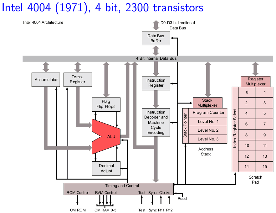
38 Intel 8085 Microprocessor Microprocessor consists of: Control unit: control microprocessor operations. ALU: performs data processing function. Registers: provide storage internal to CPU. Interrupts Internal data bus
39 The ALU In addition to the arithmetic & logic circuits, the ALU includes the accumulator, which is part of every arithmetic & logic operation. Also, the ALU includes a temporary register used for holding data temporarily during the execution of the operation. This temporary register is not accessible by the programmer.
40 Registers General Purpose Registers B, C, D, E, H & L (8 bit registers) Can be used singly Or can be used as 16 bit register pairs BC, DE, HL H & L can be used as a data pointer (holds memory address) Special Purpose Registers Accumulator (8 bit register) Store 8 bit data Store the result of an operation Store 8 bit data during I/O transfer Accumulator Flags B C D E H L Program Counter Stack Pointer Address 16 8 Data
41 Flag Register 8 bit register shows the status of the microprocessor before/after an operation S (sign flag), Z (zero flag), AC (auxillary carry flag), P (parity flag) & CY (carry flag) D7 D6 D5 D4 D3 D2 D1 D0 S Z X AC X P X CY Sign Flag Used for indicating the sign of the data in the accumulator The sign flag is set if negative (1 negative) The sign flag is reset if positive (0 positive)
42 Zero Flag Is set if result obtained after an operation is 0 Is set following an increment or decrement operation of that register Carry Flag Is set if there is a carry or borrow from arithmetic operation Carry Borrow
43 Auxillary Carry Flag Is set if there is a carry out of bit 3 Parity Flag Is set if parity is even Is cleared if parity is odd
44 The Internal Architecture We have already discussed the general purpose registers, the Accumulator, and the flags. The Program Counter (PC) This is a register that is used to control the sequencing of the execution of instructions. This register always holds the address of the next instruction. Since it holds an address, it must be 16 bits wide.
45 The Internal Architecture The Stack pointer The stack pointer is also a 16-bit register that is used to point into memory. The memory this register points to is a special area called the stack. The stack is an area of memory used to hold data that will be retreived soon. The stack is usually accessed in a Last In First Out (LIFO) fashion.
46 Non Programmable Registers Instruction Register & Decoder Instruction is stored in IR after fetched by processor Decoder decodes instruction in IR Internal Clock generator MHz internally 6.25 MHz externally
47 The Address and Data Busses The address bus has 8 signal lines A8 A15 which are unidirectional. The other 8 address bits are multiplexed (time shared) with the 8 data bits. So, the bits AD0 AD7 are bi-directional and serve as A0 A7 and D0 D7 at the same time. During the execution of the instruction, these lines carry the address bits during the early part, then during the late parts of the execution, they carry the 8 data bits. In order to separate the address from the data, we can use a latch to save the value before the function of the bits changes.
48 Demultiplexing AD7-AD A15-A8 ALE AD7-AD0 Latch A 7 - A 0 D 7 - D 0 Given that ALE operates as a pulse during T1, we will be able to latch the address. Then when ALE goes low, the address is saved and the AD7 AD0 lines can be used for their purpose as the bi-directional data lines.

49 Demultiplexing the Bus AD7 AD0 The high order address is placed on the address bus and hold for 3 clk periods, The low order address is lost after the first clk period, this address needs to be hold however we need to use latch The address AD7 AD0 is connected as inputs to the latch 74LS373. The ALE signal is connected to the enable (G) pin of the latch and the OC Output control of the latch is grounded
50 The Overall Picture Putting all of the concepts together, we get: A 15 - A 10 Chip Selection Circuit 8085 A15-A8 CS ALE AD7-AD0 Latch A 7 - A 0 A 9 - A 0 1K Byte Memory Chip WR RD IO/M D 7 - D 0 RD WR
51 Introduction to 8085 Instructions
52 The 8085 Instructions Since the 8085 is an 8-bit device it can have up to 2 8 (256) instructions. However, the 8085 only uses 246 combinations that represent a total of 74 instructions. Most of the instructions have more than one format. These instructions can be grouped into five different groups: Data Transfer Operations Arithmetic Operations Logic Operations Branch Operations Machine Control Operations
53 Instruction and Data Formats Each instruction has two parts. The first part is the task or operation to be performed. This part is called the opcode (operation code). The second part is the data to be operated on Called the operand.
54 Data Transfer Operations These operations simply COPY the data from the source to the destination. MOV, MVI, LDA, and STA They transfer: Data between registers. Data Byte to a register or memory location. Data between a memory location and a register. Data between an I\O Device and the accumulator. The data in the source is not changed.
55 The LXI instruction The 8085 provides an instruction to place the 16-bit data into the register pair in one step. LXI Rp, <16-bit address> (Load extended Immediate) The instruction LXI B 4000H will place the 16-bit number 4000 into the register pair B, C. The upper two digits are placed in the 1 st register of the pair and the lower two digits in the 2 nd LXI B 40 00H B C
56 The Memory Register Most of the instructions of the 8085 can use a memory location in place of a register. The memory location will become the memory register M. MOV M B copy the data from register B into a memory location. Which memory location? The memory location is identified by the contents of the HL register pair. The 16-bit contents of the HL register pair are treated as a 16-bit address and used to identify the memory location.
57 Using the Other Register Pairs There is also an instruction for moving data from memory to the accumulator without disturbing the contents of the H and L register. LDAX Rp (LoaD Accumulator extended) Copy the 8-bit contents of the memory location identified by the Rp register pair into the Accumulator. This instruction only uses the BC or DE pair. It does not accept the HL pair.
58 Indirect Addressing Mode Using data in memory directly (without loading first into a Microprocessor s register) is called Indirect Addressing. Indirect addressing uses the data in a register pair as a 16-bit address to identify the memory location being accessed. The HL register pair is always used in conjunction with the memory register M. The BC and DE register pairs can be used to load data into the Accumultor using indirect addressing.
59 Arithmetic Operations Addition (ADD, ADI): Any 8-bit number. The contents of a register. The contents of a memory location. Can be added to the contents of the accumulator and the result is stored in the accumulator. Subtraction (SUB, SUI): Any 8-bit number The contents of a register The contents of a memory location Can be subtracted from the contents of the accumulator. The result is stored in the accumulator.
60 Arithmetic Operations Related to Memory These instructions perform an arithmetic operation using the contents of a memory location while they are still in memory. ADD M Add the contents of M to the Accumulator SUB M Sub the contents of M from the Accumulator INR M / DCR M Increment/decrement the contents of the memory location in place. All of these use the contents of the HL register pair to identify the memory location being used.
61 Arithmetic Operations Increment (INR) and Decrement (DCR): The 8-bit contents of any memory location or any register can be directly incremented or decremented by 1. No need to disturb the contents of the accumulator.
62 Manipulating Addresses Now that we have a 16-bit address in a register pair, how do we manipulate it? It is possible to manipulate a 16-bit address stored in a register pair as one entity using some special instructions. INX Rp (Increment the 16-bit number in the register pair) DCX Rp (Decrement the 16-bit number in the register pair) The register pair is incremented or decremented as one entity. No need to worry about a carry from the lower 8-bits to the upper. It is taken care of automatically.
63 Logic Operations These instructions perform logic operations on the contents of the accumulator. ANA, ANI, ORA, ORI, XRA and XRI Source: Accumulator and An 8-bit number The contents of a register The contents of a memory location Destination: Accumulator ANA R/M AND Accumulator With Reg/Mem ANI # AND Accumulator With an 8-bit number ORA R/M OR Accumulator With Reg/Mem ORI # OR Accumulator With an 8-bit number XRA R/M XOR Accumulator With Reg/Mem XRI # XOR Accumulator With an 8-bit number
64 Logic Operations Complement: 1 s complement of the contents of the accumulator. CMA No operand
65 Additional Logic Operations Rotate Rotate the contents of the accumulator one position to the left or right. RLC Rotate the accumulator left. Bit 7 goes to bit 0 AND the Carry flag. RAL Rotate the accumulator left through the carry. Bit 7 goes to the carry and carry goes to bit 0. RRC Rotate the accumulator right. Bit 0 goes to bit 7 AND the Carry flag. RAR Rotate the accumulator right through the carry. Bit 0 goes to the carry and carry goes to bit 7.
66 RLC vs. RLA RLC Carry Flag Accumulator Carry Flag RAL Accumulator
67 Logical Operations Compare Compare the contents of a register or memory location with the contents of the accumulator. CMP R/M Compare the contents of the register or memory location to the contents of the accumulator. CPI # Compare the 8-bit number to the contents of the accumulator. The compare instruction sets the flags (Z, Cy, and S). The compare is done using an internal subtraction that does not change the contents of the accumulator. A (R / M / #)
68 Branch Operations Two types: Unconditional branch. Go to a new location no matter what. Conditional branch. Go to a new location if the condition is true.
69 Unconditional Branch JMP Address Jump to the address specified (Go to). CALL Address Jump to the address specified but treat it as a subroutine. RET Return from a subroutine. The addresses supplied to all branch operations must be 16-bits.
70 Conditional Branch Go to new location if a specified condition is met. JZ Address (Jump on Zero) Go to address specified if the Zero flag is set. JNZ Address (Jump on NOT Zero) Go to address specified if the Zero flag is not set. JC Address (Jump on Carry) Go to the address specified if the Carry flag is set. JNC Address (Jump on No Carry) Go to the address specified if the Carry flag is not set. JP Address (Jump on Plus) Go to the address specified if the Sign flag is not set JM Address (Jump on Minus) Go to the address specified if the Sign flag is set.
71 Machine Control HLT Stop executing the program. NOP No operation Exactly as it says, do nothing. Usually used for delay or to replace instructions during debugging.
72 Operand Types There are different ways for specifying the operand: There may not be an operand (implied operand) CMA The operand may be an 8-bit number (immediate data) ADI 4FH The operand may be an internal register (register) SUB B The operand may be a 16-bit address (memory address) LDA 4000H
73 Instruction Size Depending on the operand type, the instruction may have different sizes. It will occupy a different number of memory bytes. Typically, all instructions occupy one byte only. The exception is any instruction that contains immediate data or a memory address. Instructions that include immediate data use two bytes. One for the opcode and the other for the 8-bit data. Instructions that include a memory address occupy three bytes. One for the opcode, and the other two for the 16-bit address.
74 Instruction with Immediate Date Operation: Load an 8-bit number into the accumulator. MVI A, 32 Operation: MVI A Operand: The number 32 Binary Code: E 1 st byte nd byte.
75 Instruction with a Memory Address Operation: go to address Instruction: JMP 2085 Opcode: JMP Operand: 2085 Binary code: C3 1 st byte nd byte rd byte
76 Addressing Modes The microprocessor has different ways of specifying the data for the instruction. These are called addressing modes. The 8085 has four addressing modes: Implied CMA Immediate MVI B, 45 Direct LDA 4000 Indirect LDAX B Load the accumulator with the contents of the memory location whose address is stored in the register pair BC).
77 Data Formats In an 8-bit microprocessor, data can be represented in one of four formats: ASCII BCD Signed Integer Unsigned Integer. It is important to recognize that the microprocessor deals with 0 s and 1 s. It deals with values as strings of bits. It is the job of the user to add a meaning to these strings.
78 Data Formats Assume the accumulator contains the following value: There are four ways of reading this value: It is an unsigned integer expressed in binary, the equivalent decimal number would be 65. It is a number expressed in BCD (Binary Coded Decimal) format. That would make it, 41. It is an ASCII representation of a letter. That would make it the letter A. It is a string of 0 s and 1 s where the 0 th and the 6 th bits are set to 1 while all other bits are set to 0. ASCII stands for American Standard Code for Information Interchange.
79 Counters & Time Delays
80 Counters A loop counter is set up by loading a register with a certain value Then using the DCR (to decrement) and INR (to increment) the contents of the register are updated. A loop is set up with a conditional jump instruction that loops back or not depending on whether the count has reached the termination count.
81 Counters The operation of a loop counter can be described using the following flowchart. Initialize Body of loop Update the count No Is this Final Count? Yes
82 Sample ALP for implementing a loop Using DCR instruction MVI C, 15H LOOP DCR C JNZ LOOP
83 Using a Register Pair as a Loop Counter Using a single register, one can repeat a loop for a maximum count of 255 times. It is possible to increase this count by using a register pair for the loop counter instead of the single register. A minor problem arises in how to test for the final count since DCX and INX do not modify the flags. However, if the loop is looking for when the count becomes zero, we can use a small trick by ORing the two registers in the pair and then checking the zero flag.
84 Using a Register Pair as a Loop Counter The following is an example of a loop set up with a register pair as the loop counter. LXI B, 1000H LOOP DCX B MOV A, C ORA B JNZ LOOP
85 Delays It was shown in Chapter 2 that each instruction passes through different combinations of Fetch, Memory Read, and Memory Write cycles. Knowing the combinations of cycles, one can calculate how long such an instruction would require to complete. The table in Appendix F of the book contains a column with the title B/M/T. B for Number of Bytes M for Number of Machine Cycles T for Number of T-State.
86 Delays Knowing how many T-States an instruction requires, and keeping in mind that a T-State is one clock cycle long, we can calculate the time using the following formula: Delay = No. of T-States / Frequency For example a MVI instruction uses 7 T-States. Therefore, if the Microprocessor is running at 2 MHz, the instruction would require 3.5 µseconds to complete.
87 The first instruction initializes the loop counter and is executed only once requiring only 7 T-States. The following two instructions form a loop that requires 14 T-States to execute and is repeated 255 times until C becomes 0. Delay loops We can use a loop to produce a certain amount of time delay in a program. The following is an example of a delay loop: MVI C, FFH LOOP DCR C JNZ LOOP 7 T-States 4 T-States 10 T-States
88 Delay Loops (Contd.) We need to keep in mind though that in the last iteration of the loop, the JNZ instruction will fail and require only 7 T-States rather than the 10. Therefore, we must deduct 3 T-States from the total delay to get an accurate delay calculation. To calculate the delay, we use the following formula: T delay = T O + T L T delay = total delay T O = delay outside the loop T L = delay of the loop T O is the sum of all delays outside the loop.
89 Delay Loops (Contd.) Using these formulas, we can calculate the time delay for the previous example: T O = 7 T-States Delay of the MVI instruction T L = (14 X 255) - 3 = 3567 T-States 14 T-States for the 2 instructions repeated 255 times (FF 16 = ) reduced by the 3 T-States for the final JNZ.
90 Using a Register Pair as a Loop Counter Using a single register, one can repeat a loop for a maximum count of 255 times. It is possible to increase this count by using a register pair for the loop counter instead of the single register. A minor problem arises in how to test for the final count since DCX and INX do not modify the flags. However, if the loop is looking for when the count becomes zero, we can use a small trick by ORing the two registers in the pair and then checking the zero flag.
91 Using a Register Pair as a Loop Counter The following is an example of a delay loop set up with a register pair as the loop counter. LXI B, 1000H LOOP DCX B MOV A, C ORA B JNZ LOOP 10 T-States 6 T-States 4 T-States 4 T-States 10 T-States
92 Using a Register Pair as a Loop Counter Using the same formula from before, we can calculate: T O = 10 T-States The delay for the LXI instruction T L = (24 X 4096) - 3 = T- States 24 T-States for the 4 instructions in the loop repeated 4096 times ( = ) reduced by the 3 T- States for the JNZ in the last iteration.
93 Nested Loops Initialize loop 2 Nested loops can be easily setup in Assembly language by using two registers for the two loop counters and updating the right register in the right loop. In the figure, the body of loop2 can be before or after loop1. Initialize loop 1 Body of loop 1 Update the count1 No Body of loop 2 Is this Final Count? Yes Update the count 2 No Is this Final Count? Yes
94 Nested Loops for Delay Instead (or in conjunction with) Register Pairs, a nested loop structure can be used to increase the total delay produced. MVI B, 10H 7 T-States LOOP2 MVI C, FFH 7 T-States LOOP1 DCR C 4 T-States JNZ LOOP1 10 T-States DCR B 4 T-States JNZ LOOP2 10 T-States
95 Delay Calculation of Nested Loops The calculation remains the same except that it the formula must be applied recursively to each loop. Start with the inner loop, then plug that delay in the calculation of the outer loop. Delay of inner loop T O1 = 7 T-States MVI C, FFH instruction T L1 = (255 X 14) - 3 = 3567 T-States 14 T-States for the DCR C and JNZ instructions repeated 255
96 Delay Calculation of Nested Delay of outer loop T O2 = 7 T-States MVI B, 10H instruction Loops T L1 = (16 X ( )) - 3 = T-States 14 T-States for the DCR B and JNZ instructions and 3574 T-States for loop1 repeated 16 times (10 16 = ) minus 3 for the final JNZ. T Delay = = T-States Total Delay T Delay = X 0.5 µsec = msec
97 Increasing the delay The delay can be further increased by using register pairs for each of the loop counters in the nested loops setup. It can also be increased by adding dummy instructions (like NOP) in the body of the loop.
98 Timing Diagram Representation of Various Control signals generated during Execution of an Instruction. Following Buses and Control Signals must be shown in a Timing Diagram: Higher Order Address Bus. Lower Address/Data bus ALE RD WR IO/M
99 Timing Diagram Instruction: A000h MOV A,B Corresponding Coding: A000h 78
100 Timing Diagram Instruction: A000h MOV A,B Corresponding Coding: A000h 78 OFC 8085 Memory
101 Timing Diagram Instruction: A000h MOV A,B Corresponding Coding: A000h 78 T1 T2 T3 T4 A0h A15- A8 (Higher Order Address bus) 00h 78h ALE RD OFC WR 8085 Memory IO/M Op-code fetch Cycle
102 Timing Diagram Instruction: A000h MVI A,45h Corresponding Coding: A000h 3E A001h 45
103 Timing Diagram Instruction: A000h MVI A,45h Corresponding Coding: A000h 3E A001h 45 OFC MEMR 8085 Memory
104 Timing Diagram T1 T2 T3 T4 T5 T6 T7 A0h A15- A8 (Higher Order Address bus) A0h Instruction: A000h MVI A,45h Corresponding Coding: A000h 3E A001h 45 00h 3Eh 01h 45h DA7-DA0 (Lower order address/data Bus) ALE RD WR IO/M Op-Code Fetch Cycle Memory Read Cycle
105 Timing Diagram Instruction: A000h LXI A,FO45h Corresponding Coding: A000h 21 A001h 45 A002h F0
106 Timing Diagram Instruction: A000h LXI A,FO45h Corresponding Coding: A000h 21 A001h 45 A002h F0 OFC MEMR MEMR 8085 Memory
107 Timing Diagram Op-Code Fetch Cycle Memory Read Cycle Memory Read Cycle T1 T2 T3 T4 T5 T6 T7 T8 T9 T10 A15- A8 (Higher Order Address bus) A0h A0h A0h 00h 21h 01h 45h 02h F0h DA7-DA0 (Lower order address/data Bus) ALE RD WR IO/M
108 Timing Diagram Instruction: A000h MOV A,M Corresponding Coding: A000h 7E
109 Timing Diagram Instruction: A000h MOV A,M Corresponding Coding: A000h 7E OFC MEMR 8085 Memory
110 Timing Diagram T1 T2 T3 T4 T5 T6 T7 A15- A8 (Higher Order Address bus) A0h Content Of Reg H Instruction: A000h MOV A,M Corresponding Coding: A000h 7E 00h 7Eh L Reg Content Of M DA7-DA0 (Lower order address/data Bus) ALE RD WR IO/M Op-Code Fetch Cycle Memory Read Cycle
111 Timing Diagram Instruction: A000h MOV M,A Corresponding Coding: A000h 77
112 Timing Diagram Instruction: A000h MOV M,A Corresponding Coding: A000h 77 OFC MEMW 8085 Memory
113 Timing Diagram T1 T2 T3 T4 T5 T6 T7 A15- A8 (Higher Order Address bus) A0h Content Of Reg H Instruction: A000h MOV M,A Corresponding Coding: A000h 77 00h 7Eh L Reg Content of Reg A DA7-DA0 (Lower order address/data Bus) ALE RD WR IO/M Op-Code Fetch Cycle Memory Write Cycle
114 Chapter 9 Stack and Subroutines
115 The Stack The stack is an area of memory identified by the programmer for temporary storage of information. The stack is a LIFO structure. Last In First Out. The stack normally grows backwards into memory. In other words, the programmer defines the bottom of the stack and the stack grows up into reducing address range. The Stack grows backwards into memory Memory Bottom of the Stack
116 The Stack Given that the stack grows backwards into memory, it is customary to place the bottom of the stack at the end of memory to keep it as far away from user programs as possible. In the 8085, the stack is defined by setting the SP (Stack Pointer) register. LXI SP, FFFFH This sets the Stack Pointer to location FFFFH (end of memory for the 8085).
117 Saving Information on the Stack Information is saved on the stack by PUSHing it on. It is retrieved from the stack by POPing it off. The 8085 provides two instructions: PUSH and POP for storing information on the stack and retrieving it back. Both PUSH and POP work with register pairs ONLY.
118 The PUSH Instruction PUSH B Decrement SP Copy the contents of register B to the memory location pointed to by SP Decrement SP B C 12 F3 Copy the contents of register C to the memory FFFB location pointed to by FFFC FFFD SP FFFE FFFF F3 12 SP
119 The POP Instruction POP D Copy the contents of the memory location pointed to by the SP to register E Increment SP Copy the contents of the memory location D E pointed to by 12 the F3 SP to register D Increment SP FFFB FFFC FFFD FFFE FFFF F3 12 SP
120 The SP pointer always points to the top of the stack. Operation of the Stack During pushing, the stack operates in a decrement then store style. The stack pointer is decremented first, then the information is placed on the stack. During poping, the stack operates in a use then increment style. The information is retrieved from the top of the the stack and then the pointer is incremented.
121 LIFO The order of PUSHs and POPs must be opposite of each other in order to retrieve information back into its original location. PUSH B PUSH D... POP D POP B
122 The PSW Register Pair The 8085 recognizes one additional register pair called the PSW (Program Status Word). This register pair is made up of the Accumulator and the Flags registers. It is possible to push the PSW onto the stack, do whatever operations are needed, then POP it off of the stack. The result is that the contents of the Accumulator and the status of the Flags are returned to what they were before the operations were executed.
123 Subroutines A subroutine is a group of instructions that will be used repeatedly in different locations of the program. Rather than repeat the same instructions several times, they can be grouped into a subroutine that is called from the different locations. In Assembly language, a subroutine can exist anywhere in the code. However, it is customary to place subroutines separately from the main program.
124 Subroutines The 8085 has two instructions for dealing with subroutines. The CALL instruction is used to redirect program execution to the subroutine. The RTE insutruction is used to return the execution to the calling routine.
125 The CALL Instruction CALL 4000H Push the address of the instruction immediately following the CALL onto the stack 2000 CALL Load the program PC counter with the 16-bit address supplied with the CALL FFFB FFFC instruction. FFFD FFFE FFFF SP
126 The RTE Instruction RTE Retrieve the return address from the top of the stack Load the program counter with the return address. PC FFFB FFFC 4015 RTE FFFD 03 SP FFFE 20 FFFF
127 Cautions The CALL instruction places the return address at the two memory locations immediately before where the Stack Pointer is pointing. You must set the SP correctly BEFORE using the CALL instruction. The RTE instruction takes the contents of the two memory locations at the top of the stack and uses these as the return address. Do not modify the stack pointer in a subroutine. You will loose the return address.
128 Passing Data to a Subroutine In Assembly Language data is passed to a subroutine through registers. The data is stored in one of the registers by the calling program and the subroutine uses the value from the register. The other possibility is to use agreed upon memory locations. The calling program stores the data in the memory location and the subroutine retrieves the data from the location and uses it.
129 Call by Reference and Call by Value If the subroutine performs operations on the contents of the registers, then these modifications will be transferred back to the calling program upon returning from a subroutine. Call by reference If this is not desired, the subroutine should PUSH all the registers it needs on the stack on entry and POP them on return. The original values are restored before execution returns to the calling program.
130 Cautions with PUSH and POP PUSH and POP should be used in opposite order. There has to be as many POP s as there are PUSH s. If not, the RET statement will pick up the wrong information from the top of the stack and the program will fail. It is not advisable to place PUSH or POP inside a loop.
131 Conditional CALL and RTE Instructions The 8085 supports conditional CALL and conditional RTE instructions. The same conditions used with conditional JUMP instructions can be used. CC, call subroutine if Carry flag is set. CNC, call subroutine if Carry flag is not set RC, return from subroutine if Carry flag is set RNC, return from subroutine if Carry flag is not set Etc.
132 A Proper Subroutine According to Software Engineering practices, a proper subroutine: Is only entered with a CALL and exited with an RTE Has a single entry point Do not use a CALL statement to jump into different points of the same subroutine. Has a single exit point There should be one return statement from any subroutine. Following these rules, there should not be any confusion with PUSH and POP usage.
PART B QUESTIONS AND ANSWERS UNIT I
 PART B QUESTIONS AND ANSWERS UNIT I 1. Explain the architecture of 8085 microprocessor? Logic pin out of 8085 microprocessor Address bus: unidirectional bus, used as high order bus Data bus: bi-directional
8085 INSTRUCTION SET
 DATA TRANSFER INSTRUCTIONS Opcode Operand Description 8085 INSTRUCTION SET INSTRUCTION DETAILS Copy from source to destination OV Rd, Rs This instruction copies the contents of the source, Rs register
MACHINE ARCHITECTURE & LANGUAGE
 in the name of God the compassionate, the merciful notes on MACHINE ARCHITECTURE & LANGUAGE compiled by Jumong Chap. 9 Microprocessor Fundamentals A system designer should consider a microprocessor-based
MICROPROCESSOR AND MICROCOMPUTER BASICS
 Introduction MICROPROCESSOR AND MICROCOMPUTER BASICS At present there are many types and sizes of computers available. These computers are designed and constructed based on digital and Integrated Circuit
MICROPROCESSOR. Exclusive for IACE Students www.iace.co.in iacehyd.blogspot.in Ph: 9700077455/422 Page 1
 MICROPROCESSOR A microprocessor incorporates the functions of a computer s central processing unit (CPU) on a single Integrated (IC), or at most a few integrated circuit. It is a multipurpose, programmable
LABORATORY MANUAL EE0310 MICROPROCESSOR & MICROCONTROLLER LAB
 LABORATORY MANUAL EE0310 MICROPROCESSOR & MICROCONTROLLER LAB DEPARTMENT OF ELECTRICAL & ELECTRONICS ENGINEERING FACULTY OF ENGINEERING & TECHNOLOGY SRM UNIVERSITY, Kattankulathur 603 203 1 LIST OF EXEPRIMENTS
150127-Microprocessor & Assembly Language
 Chapter 3 Z80 Microprocessor Architecture The Z 80 is one of the most talented 8 bit microprocessors, and many microprocessor-based systems are designed around the Z80. The Z80 microprocessor needs an
COMPUTERS ORGANIZATION 2ND YEAR COMPUTE SCIENCE MANAGEMENT ENGINEERING JOSÉ GARCÍA RODRÍGUEZ JOSÉ ANTONIO SERRA PÉREZ
 COMPUTERS ORGANIZATION 2ND YEAR COMPUTE SCIENCE MANAGEMENT ENGINEERING UNIT 1 - INTRODUCTION JOSÉ GARCÍA RODRÍGUEZ JOSÉ ANTONIO SERRA PÉREZ Unit 1.MaNoTaS 1 Definitions (I) Description A computer is: A
(Refer Slide Time: 00:01:16 min)
") Digital Computer Organization Prof. P. K. Biswas Department of Electronic & Electrical Communication Engineering Indian Institute of Technology, Kharagpur Lecture No. # 04 CPU Design: Tirning & Control
Digital Computer Organization Prof. P. K. Biswas Department of Electronic & Electrical Communication Engineering Indian Institute of Technology, Kharagpur Lecture No. # 04 CPU Design: Tirning & Control
Advanced Computer Architecture-CS501. Computer Systems Design and Architecture 2.1, 2.2, 3.2
 Lecture Handout Computer Architecture Lecture No. 2 Reading Material Vincent P. Heuring&Harry F. Jordan Chapter 2,Chapter3 Computer Systems Design and Architecture 2.1, 2.2, 3.2 Summary 1) A taxonomy of
TIMING DIAGRAM O 8085
 5 TIMING DIAGRAM O 8085 5.1 INTRODUCTION Timing diagram is the display of initiation of read/write and transfer of data operations under the control of 3-status signals IO / M, S 1, and S 0. As the heartbeat
CHAPTER 7: The CPU and Memory
 CHAPTER 7: The CPU and Memory The Architecture of Computer Hardware, Systems Software & Networking: An Information Technology Approach 4th Edition, Irv Englander John Wiley and Sons 2010 PowerPoint slides
1 Classical Universal Computer 3
 Chapter 6: Machine Language and Assembler Christian Jacob 1 Classical Universal Computer 3 1.1 Von Neumann Architecture 3 1.2 CPU and RAM 5 1.3 Arithmetic Logical Unit (ALU) 6 1.4 Arithmetic Logical Unit
8051 hardware summary
 8051 hardware summary 8051 block diagram 8051 pinouts + 5V ports port 0 port 1 port 2 port 3 : dual-purpose (general-purpose, external memory address and data) : dedicated (interfacing to external devices)
Z80 Instruction Set. Z80 Assembly Language
 75 Z80 Assembly Language The assembly language allows the user to write a program without concern for memory addresses or machine instruction formats. It uses symbolic addresses to identify memory locations
Microcontroller Basics A microcontroller is a small, low-cost computer-on-a-chip which usually includes:
 Microcontroller Basics A microcontroller is a small, low-cost computer-on-a-chip which usually includes: An 8 or 16 bit microprocessor (CPU). A small amount of RAM. Programmable ROM and/or flash memory.
MICROPROCESSOR BCA IV Sem MULTIPLE CHOICE QUESTIONS
 MICROPROCESSOR BCA IV Sem MULTIPLE CHOICE QUESTIONS 1) Which is the microprocessor comprises: a. Register section b. One or more ALU c. Control unit 2) What is the store by register? a. data b. operands
CPU Organization and Assembly Language
 COS 140 Foundations of Computer Science School of Computing and Information Science University of Maine October 2, 2015 Outline 1 2 3 4 5 6 7 8 Homework and announcements Reading: Chapter 12 Homework:
Computer organization
 Computer organization Computer design an application of digital logic design procedures Computer = processing unit + memory system Processing unit = control + datapath Control = finite state machine inputs
Z80 Microprocessors Z80 CPU. User Manual UM008006-0714. Copyright 2014 Zilog, Inc. All rights reserved. www.zilog.com
 Z80 Microprocessors Z80 CPU UM008006-0714 Copyright 2014 Zilog, Inc. All rights reserved. www.zilog.com ii Warning: DO NOT USE THIS PRODUCT IN LIFE SUPPORT SYSTEMS. LIFE SUPPORT POLICY ZILOG S PRODUCTS
A s we saw in Chapter 4, a CPU contains three main sections: the register section,
 6 CPU Design A s we saw in Chapter 4, a CPU contains three main sections: the register section, the arithmetic/logic unit (ALU), and the control unit. These sections work together to perform the sequences
PROBLEMS (Cap. 4 - Istruzioni macchina)
") 98 CHAPTER 2 MACHINE INSTRUCTIONS AND PROGRAMS PROBLEMS (Cap. 4 - Istruzioni macchina) 2.1 Represent the decimal values 5, 2, 14, 10, 26, 19, 51, and 43, as signed, 7-bit numbers in the following binary
98 CHAPTER 2 MACHINE INSTRUCTIONS AND PROGRAMS PROBLEMS (Cap. 4 - Istruzioni macchina) 2.1 Represent the decimal values 5, 2, 14, 10, 26, 19, 51, and 43, as signed, 7-bit numbers in the following binary
DEPARTMENT OF COMPUTER SCIENCE & ENGINEERING Question Bank Subject Name: EC6504 - Microprocessor & Microcontroller Year/Sem : II/IV
 DEPARTMENT OF COMPUTER SCIENCE & ENGINEERING Question Bank Subject Name: EC6504 - Microprocessor & Microcontroller Year/Sem : II/IV UNIT I THE 8086 MICROPROCESSOR 1. What is the purpose of segment registers
Computer Organization and Architecture
 Computer Organization and Architecture Chapter 11 Instruction Sets: Addressing Modes and Formats Instruction Set Design One goal of instruction set design is to minimize instruction length Another goal
8085 MICROPROCESSOR PROGRAMS
 8085 MICROPROCESSOR PROGRAMS 1 ADDITION OF TWO 8 BIT NUMBERS AIM: To perform addition of two 8 bit numbers using 8085. ALGORITHM: 1) Start the program by loading the first data into Accumulator. 2) Move
Central Processing Unit (CPU)
") Central Processing Unit (CPU) CPU is the heart and brain It interprets and executes machine level instructions Controls data transfer from/to Main Memory (MM) and CPU Detects any errors In the following
Central Processing Unit (CPU) CPU is the heart and brain It interprets and executes machine level instructions Controls data transfer from/to Main Memory (MM) and CPU Detects any errors In the following
Chapter 5 Instructor's Manual
 The Essentials of Computer Organization and Architecture Linda Null and Julia Lobur Jones and Bartlett Publishers, 2003 Chapter 5 Instructor's Manual Chapter Objectives Chapter 5, A Closer Look at Instruction
How It All Works. Other M68000 Updates. Basic Control Signals. Basic Control Signals
 CPU Architectures Motorola 68000 Several CPU architectures exist currently: Motorola Intel AMD (Advanced Micro Devices) PowerPC Pick one to study; others will be variations on this. Arbitrary pick: Motorola
Chapter 4 Register Transfer and Microoperations. Section 4.1 Register Transfer Language
 Chapter 4 Register Transfer and Microoperations Section 4.1 Register Transfer Language Digital systems are composed of modules that are constructed from digital components, such as registers, decoders,
8-Bit Flash Microcontroller for Smart Cards. AT89SCXXXXA Summary. Features. Description. Complete datasheet available under NDA
 Features Compatible with MCS-51 products On-chip Flash Program Memory Endurance: 1,000 Write/Erase Cycles On-chip EEPROM Data Memory Endurance: 100,000 Write/Erase Cycles 512 x 8-bit RAM ISO 7816 I/O Port
Faculty of Engineering Student Number:
 Philadelphia University Student Name: Faculty of Engineering Student Number: Dept. of Computer Engineering Final Exam, First Semester: 2012/2013 Course Title: Microprocessors Date: 17/01//2013 Course No:
Let s put together a Manual Processor
 Lecture 14 Let s put together a Manual Processor Hardware Lecture 14 Slide 1 The processor Inside every computer there is at least one processor which can take an instruction, some operands and produce
CHAPTER 4 MARIE: An Introduction to a Simple Computer
 CHAPTER 4 MARIE: An Introduction to a Simple Computer 4.1 Introduction 195 4.2 CPU Basics and Organization 195 4.2.1 The Registers 196 4.2.2 The ALU 197 4.2.3 The Control Unit 197 4.3 The Bus 197 4.4 Clocks
Notes on Assembly Language
 Notes on Assembly Language Brief introduction to assembly programming The main components of a computer that take part in the execution of a program written in assembly code are the following: A set of
UNIVERSITY OF CALIFORNIA, DAVIS Department of Electrical and Computer Engineering. EEC180B Lab 7: MISP Processor Design Spring 1995
 UNIVERSITY OF CALIFORNIA, DAVIS Department of Electrical and Computer Engineering EEC180B Lab 7: MISP Processor Design Spring 1995 Objective: In this lab, you will complete the design of the MISP processor,
Instruction Set Architecture
 Instruction Set Architecture Consider x := y+z. (x, y, z are memory variables) 1-address instructions 2-address instructions LOAD y (r :=y) ADD y,z (y := y+z) ADD z (r:=r+z) MOVE x,y (x := y) STORE x (x:=r)
İSTANBUL AYDIN UNIVERSITY
 İSTANBUL AYDIN UNIVERSITY FACULTY OF ENGİNEERİNG SOFTWARE ENGINEERING THE PROJECT OF THE INSTRUCTION SET COMPUTER ORGANIZATION GÖZDE ARAS B1205.090015 Instructor: Prof. Dr. HASAN HÜSEYİN BALIK DECEMBER
Management Challenge. Managing Hardware Assets. Central Processing Unit. What is a Computer System?
 Management Challenge Managing Hardware Assets What computer processing and storage capability does our organization need to handle its information and business transactions? What arrangement of computers
Chapter 2 Logic Gates and Introduction to Computer Architecture
 Chapter 2 Logic Gates and Introduction to Computer Architecture 2.1 Introduction The basic components of an Integrated Circuit (IC) is logic gates which made of transistors, in digital system there are
Instruction Set Architecture (ISA)
") Instruction Set Architecture (ISA) * Instruction set architecture of a machine fills the semantic gap between the user and the machine. * ISA serves as the starting point for the design of a new machine
Instruction Set Architecture (ISA) * Instruction set architecture of a machine fills the semantic gap between the user and the machine. * ISA serves as the starting point for the design of a new machine
CPU Organisation and Operation
 CPU Organisation and Operation The Fetch-Execute Cycle The operation of the CPU 1 is usually described in terms of the Fetch-Execute cycle. 2 Fetch-Execute Cycle Fetch the Instruction Increment the Program
Central Processing Unit
 Chapter 4 Central Processing Unit 1. CPU organization and operation flowchart 1.1. General concepts The primary function of the Central Processing Unit is to execute sequences of instructions representing
CS101 Lecture 26: Low Level Programming. John Magee 30 July 2013 Some material copyright Jones and Bartlett. Overview/Questions
 CS101 Lecture 26: Low Level Programming John Magee 30 July 2013 Some material copyright Jones and Bartlett 1 Overview/Questions What did we do last time? How can we control the computer s circuits? How
MACHINE INSTRUCTIONS AND PROGRAMS
 CHAPTER 2 MACHINE INSTRUCTIONS AND PROGRAMS CHAPTER OBJECTIVES In this chapter you will learn about: Machine instructions and program execution, including branching and subroutine call and return operations
PROGRAMMABLE LOGIC CONTROLLERS Unit code: A/601/1625 QCF level: 4 Credit value: 15 TUTORIAL OUTCOME 2 Part 1
 UNIT 22: PROGRAMMABLE LOGIC CONTROLLERS Unit code: A/601/1625 QCF level: 4 Credit value: 15 TUTORIAL OUTCOME 2 Part 1 This work covers part of outcome 2 of the Edexcel standard module. The material is
Interfacing Analog to Digital Data Converters
 Converters In most of the cases, the PIO 8255 is used for interfacing the analog to digital converters with microprocessor. We have already studied 8255 interfacing with 8086 as an I/O port, in previous
An Introduction to the ARM 7 Architecture
 An Introduction to the ARM 7 Architecture Trevor Martin CEng, MIEE Technical Director This article gives an overview of the ARM 7 architecture and a description of its major features for a developer new
Z80 Family. CPU User Manual
 Z80 Family CPU User Manual User Manual ZiLOG Worldwide Headquarters 532 Race Street San Jose, CA 95126-3432 Telephone: 408.558.8500 Fax: 408.558.8300 www.zilog.com This publication is subject to replacement
BASIC COMPUTER ORGANIZATION AND DESIGN
 1 BASIC COMPUTER ORGANIZATION AND DESIGN Instruction Codes Computer Registers Computer Instructions Timing and Control Instruction Cycle Memory Reference Instructions Input-Output and Interrupt Complete
The x86 PC: Assembly Language, Design, and Interfacing 5 th Edition
 Online Instructor s Manual to accompany The x86 PC: Assembly Language, Design, and Interfacing 5 th Edition Muhammad Ali Mazidi Janice Gillispie Mazidi Danny Causey Prentice Hall Boston Columbus Indianapolis
A single register, called the accumulator, stores the. operand before the operation, and stores the result. Add y # add y from memory to the acc
 Other architectures Example. Accumulator-based machines A single register, called the accumulator, stores the operand before the operation, and stores the result after the operation. Load x # into acc
what operations can it perform? how does it perform them? on what kind of data? where are instructions and data stored?
 Inside the CPU how does the CPU work? what operations can it perform? how does it perform them? on what kind of data? where are instructions and data stored? some short, boring programs to illustrate the
The Hexadecimal Number System and Memory Addressing
 APPENDIX C The Hexadecimal Number System and Memory Addressing U nderstanding the number system and the coding system that computers use to store data and communicate with each other is fundamental to
Instruction Set Architecture. or How to talk to computers if you aren t in Star Trek
 Instruction Set Architecture or How to talk to computers if you aren t in Star Trek The Instruction Set Architecture Application Compiler Instr. Set Proc. Operating System I/O system Instruction Set Architecture
Chapter 6. Inside the System Unit. What You Will Learn... Computers Are Your Future. What You Will Learn... Describing Hardware Performance
 What You Will Learn... Computers Are Your Future Chapter 6 Understand how computers represent data Understand the measurements used to describe data transfer rates and data storage capacity List the components
OVERVIEW OF MICROPROCESSORS
 C HAPTER 1 OVERVIEW OF MICROPROCESSORS 1.1 GENERAL A microprocessor is one of the most exciting technological innovations in electronics since the appearance of the transistor in 1948. This wonder device
Administrative Issues
 CSC 3210 Computer Organization and Programming Introduction and Overview Dr. Anu Bourgeois (modified by Yuan Long) Administrative Issues Required Prerequisites CSc 2010 Intro to CSc CSc 2310 Java Programming
8254 PROGRAMMABLE INTERVAL TIMER
 PROGRAMMABLE INTERVAL TIMER Y Y Y Compatible with All Intel and Most Other Microprocessors Handles Inputs from DC to 10 MHz 8 MHz 8254 10 MHz 8254-2 Status Read-Back Command Y Y Y Y Y Six Programmable
2011, The McGraw-Hill Companies, Inc. Chapter 3
 Chapter 3 3.1 Decimal System The radix or base of a number system determines the total number of different symbols or digits used by that system. The decimal system has a base of 10 with the digits 0 through
Digital System Design Prof. D Roychoudhry Department of Computer Science and Engineering Indian Institute of Technology, Kharagpur
 Digital System Design Prof. D Roychoudhry Department of Computer Science and Engineering Indian Institute of Technology, Kharagpur Lecture - 04 Digital Logic II May, I before starting the today s lecture
M6800. Assembly Language Programming
 M6800 Assembly Language Programming 1 3. MC6802 MICROPROCESSOR MC6802 microprocessor runs in 1MHz clock cycle. It has 64 Kbyte memory address capacity using 16-bit addressing path (A0-A15). The 8-bit data
ASSEMBLY LANGUAGE PROGRAMMING (6800) (R. Horvath, Introduction to Microprocessors, Chapter 6)
 (R. Horvath, Introduction to Microprocessors, Chapter 6)") ASSEMBLY LANGUAGE PROGRAMMING (6800) (R. Horvath, Introduction to Microprocessors, Chapter 6) 1 COMPUTER LANGUAGES In order for a computer to be able to execute a program, the program must first be present
ASSEMBLY LANGUAGE PROGRAMMING (6800) (R. Horvath, Introduction to Microprocessors, Chapter 6) 1 COMPUTER LANGUAGES In order for a computer to be able to execute a program, the program must first be present
Instruction Set Design
 Instruction Set Design Instruction Set Architecture: to what purpose? ISA provides the level of abstraction between the software and the hardware One of the most important abstraction in CS It s narrow,
Computer Organization. and Instruction Execution. August 22
 Computer Organization and Instruction Execution August 22 CSC201 Section 002 Fall, 2000 The Main Parts of a Computer CSC201 Section Copyright 2000, Douglas Reeves 2 I/O and Storage Devices (lots of devices,
a storage location directly on the CPU, used for temporary storage of small amounts of data during processing.
 CS143 Handout 18 Summer 2008 30 July, 2008 Processor Architectures Handout written by Maggie Johnson and revised by Julie Zelenski. Architecture Vocabulary Let s review a few relevant hardware definitions:
Here is a diagram of a simple computer system: (this diagram will be the one needed for exams) CPU. cache
 CPU. cache") Computer Systems Here is a diagram of a simple computer system: (this diagram will be the one needed for exams) CPU cache bus memory controller keyboard controller display controller disk Computer Systems
Computer Systems Here is a diagram of a simple computer system: (this diagram will be the one needed for exams) CPU cache bus memory controller keyboard controller display controller disk Computer Systems
Chapter 1 Computer System Overview
 Operating Systems: Internals and Design Principles Chapter 1 Computer System Overview Eighth Edition By William Stallings Operating System Exploits the hardware resources of one or more processors Provides
Programming Logic controllers
 Programming Logic controllers Programmable Logic Controller (PLC) is a microprocessor based system that uses programmable memory to store instructions and implement functions such as logic, sequencing,
Flash Microcontroller. Architectural Overview. Features. Block Diagram. Figure 1. Block Diagram of the AT89C core
 Features 8-Bit CPU Optimized for Control Applications Extensive Boolean Processing Capabilities (Single-Bit Logic) On-Chip Flash Program Memory On-Chip Data RAM Bidirectional and Individually Addressable
================================================================
 ==== ==== ================================================================ DR 6502 AER 201S Engineering Design 6502 Execution Simulator ================================================================
Computer Systems Design and Architecture by V. Heuring and H. Jordan
 1-1 Chapter 1 - The General Purpose Machine Computer Systems Design and Architecture Vincent P. Heuring and Harry F. Jordan Department of Electrical and Computer Engineering University of Colorado - Boulder
An Overview of Stack Architecture and the PSC 1000 Microprocessor
 An Overview of Stack Architecture and the PSC 1000 Microprocessor Introduction A stack is an important data handling structure used in computing. Specifically, a stack is a dynamic set of elements in which
2) Write in detail the issues in the design of code generator.
 Write in detail the issues in the design of code generator.") COMPUTER SCIENCE AND ENGINEERING VI SEM CSE Principles of Compiler Design Unit-IV Question and answers UNIT IV CODE GENERATION 9 Issues in the design of code generator The target machine Runtime Storage
COMPUTER SCIENCE AND ENGINEERING VI SEM CSE Principles of Compiler Design Unit-IV Question and answers UNIT IV CODE GENERATION 9 Issues in the design of code generator The target machine Runtime Storage
Comp 255Q - 1M: Computer Organization Lab #3 - Machine Language Programs for the PDP-8
 Comp 255Q - 1M: Computer Organization Lab #3 - Machine Language Programs for the PDP-8 January 22, 2013 Name: Grade /10 Introduction: In this lab you will write, test, and execute a number of simple PDP-8
The string of digits 101101 in the binary number system represents the quantity
 Data Representation Section 3.1 Data Types Registers contain either data or control information Control information is a bit or group of bits used to specify the sequence of command signals needed for
Computers. Hardware. The Central Processing Unit (CPU) CMPT 125: Lecture 1: Understanding the Computer
 CMPT 125: Lecture 1: Understanding the Computer") Computers CMPT 125: Lecture 1: Understanding the Computer Tamara Smyth, tamaras@cs.sfu.ca School of Computing Science, Simon Fraser University January 3, 2009 A computer performs 2 basic functions: 1.
Computers CMPT 125: Lecture 1: Understanding the Computer Tamara Smyth, tamaras@cs.sfu.ca School of Computing Science, Simon Fraser University January 3, 2009 A computer performs 2 basic functions: 1.
LSN 2 Computer Processors
 LSN 2 Computer Processors Department of Engineering Technology LSN 2 Computer Processors Microprocessors Design Instruction set Processor organization Processor performance Bandwidth Clock speed LSN 2
Keil C51 Cross Compiler
 Keil C51 Cross Compiler ANSI C Compiler Generates fast compact code for the 8051 and it s derivatives Advantages of C over Assembler Do not need to know the microcontroller instruction set Register allocation
Microprocessor or Microcontroller?
 Microprocessor or Microcontroller? A little History What is a computer? [Merriam-Webster Dictionary] one that computes; specifically : programmable electronic device that can store, retrieve, and process
CHAPTER 11: Flip Flops
 CHAPTER 11: Flip Flops In this chapter, you will be building the part of the circuit that controls the command sequencing. The required circuit must operate the counter and the memory chip. When the teach
Introduction to Microcontrollers
 Introduction to Microcontrollers Motorola M68HC11 Specs Assembly Programming Language BUFFALO Topics of Discussion Microcontrollers M68HC11 Package & Pinouts Accumulators Index Registers Special Registers
A3 Computer Architecture
 A3 Computer Architecture Engineering Science 3rd year A3 Lectures Prof David Murray david.murray@eng.ox.ac.uk www.robots.ox.ac.uk/ dwm/courses/3co Michaelmas 2000 1 / 1 6. Stacks, Subroutines, and Memory
Systems I: Computer Organization and Architecture
 Systems I: Computer Organization and Architecture Lecture : Microprogrammed Control Microprogramming The control unit is responsible for initiating the sequence of microoperations that comprise instructions.
Decimal Number (base 10) Binary Number (base 2)
 Binary Number (base 2)") LECTURE 5. BINARY COUNTER Before starting with counters there is some vital information that needs to be understood. The most important is the fact that since the outputs of a digital chip can only be
LECTURE 5. BINARY COUNTER Before starting with counters there is some vital information that needs to be understood. The most important is the fact that since the outputs of a digital chip can only be
SECTION C [short essay] [Not to exceed 120 words, Answer any SIX questions. Each question carries FOUR marks] 6 x 4=24 marks
![SECTION C [short essay] [Not to exceed 120 words, Answer any SIX questions. Each question carries FOUR marks] 6 x 4=24 marks](/thumbs/35/17285180.jpg "SECTION C [short essay] [Not to exceed 120 words, Answer any SIX questions. Each question carries FOUR marks] 6 x 4=24 marks") UNIVERSITY OF KERALA First Degree Programme in Computer Applications Model Question Paper Semester I Course Code- CP 1121 Introduction to Computer Science TIME : 3 hrs Maximum Mark: 80 SECTION A [Very
UNIVERSITY OF KERALA First Degree Programme in Computer Applications Model Question Paper Semester I Course Code- CP 1121 Introduction to Computer Science TIME : 3 hrs Maximum Mark: 80 SECTION A [Very
EC 362 Problem Set #2
 EC 362 Problem Set #2 1) Using Single Precision IEEE 754, what is FF28 0000? 2) Suppose the fraction enhanced of a processor is 40% and the speedup of the enhancement was tenfold. What is the overall speedup?
Lecture 3 Addressing Modes, Instruction Samples, Machine Code, Instruction Execution Cycle
 Lecture 3 Addressing Modes, Instruction Samples, Machine Code, Instruction Execution Cycle Contents 3.1. Register Transfer Notation... 2 3.2. HCS12 Addressing Modes... 2 1. Inherent Mode (INH)... 2 2.
Computer Architecture Lecture 2: Instruction Set Principles (Appendix A) Chih Wei Liu 劉 志 尉 National Chiao Tung University cwliu@twins.ee.nctu.edu.
 Chih Wei Liu 劉 志 尉 National Chiao Tung University cwliu@twins.ee.nctu.edu.") Computer Architecture Lecture 2: Instruction Set Principles (Appendix A) Chih Wei Liu 劉 志 尉 National Chiao Tung University cwliu@twins.ee.nctu.edu.tw Review Computers in mid 50 s Hardware was expensive
Computer Architecture Lecture 2: Instruction Set Principles (Appendix A) Chih Wei Liu 劉 志 尉 National Chiao Tung University cwliu@twins.ee.nctu.edu.tw Review Computers in mid 50 s Hardware was expensive
Microprocessor/Microcontroller. Introduction
 Microprocessor/Microcontroller Introduction Microprocessor/Microcontroller microprocessor - also known as a CU or central processing unit - is a complete computation engine that is fabricated on a single
BCD (ASCII) Arithmetic. Where and Why is BCD used? Packed BCD, ASCII, Unpacked BCD. BCD Adjustment Instructions AAA. Example
 Arithmetic. Where and Why is BCD used? Packed BCD, ASCII, Unpacked BCD. BCD Adjustment Instructions AAA. Example") BCD (ASCII) Arithmetic We will first look at unpacked BCD which means strings that look like '4567'. Bytes then look like 34h 35h 36h 37h OR: 04h 05h 06h 07h x86 processors also have instructions for packed
BCD (ASCII) Arithmetic We will first look at unpacked BCD which means strings that look like '4567'. Bytes then look like 34h 35h 36h 37h OR: 04h 05h 06h 07h x86 processors also have instructions for packed
The AVR Microcontroller and C Compiler Co-Design Dr. Gaute Myklebust ATMEL Corporation ATMEL Development Center, Trondheim, Norway
 The AVR Microcontroller and C Compiler Co-Design Dr. Gaute Myklebust ATMEL Corporation ATMEL Development Center, Trondheim, Norway Abstract High Level Languages (HLLs) are rapidly becoming the standard
Chapter 2 Basic Structure of Computers. Jin-Fu Li Department of Electrical Engineering National Central University Jungli, Taiwan
 Chapter 2 Basic Structure of Computers Jin-Fu Li Department of Electrical Engineering National Central University Jungli, Taiwan Outline Functional Units Basic Operational Concepts Bus Structures Software
1 Computer hardware. Peripheral Bus device "B" Peripheral device. controller. Memory. Central Processing Unit (CPU)
") 1 1 Computer hardware Most computers are organized as shown in Figure 1.1. A computer contains several major subsystems --- such as the Central Processing Unit (CPU), memory, and peripheral device controllers.
1 1 Computer hardware Most computers are organized as shown in Figure 1.1. A computer contains several major subsystems --- such as the Central Processing Unit (CPU), memory, and peripheral device controllers.
AUTOMATIC NIGHT LAMP WITH MORNING ALARM USING MICROPROCESSOR
 AUTOMATIC NIGHT LAMP WITH MORNING ALARM USING MICROPROCESSOR INTRODUCTION This Project "Automatic Night Lamp with Morning Alarm" was developed using Microprocessor. It is the Heart of the system. The sensors
CSE2102 Digital Design II - Topics CSE2102 - Digital Design II
 CSE2102 Digital Design II - Topics CSE2102 - Digital Design II 6 - Microprocessor Interfacing - Memory and Peripheral Dr. Tim Ferguson, Monash University. AUSTRALIA. Tel: +61-3-99053227 FAX: +61-3-99053574
Chapter 7D The Java Virtual Machine
 This sub chapter discusses another architecture, that of the JVM (Java Virtual Machine). In general, a VM (Virtual Machine) is a hypothetical machine (implemented in either hardware or software) that directly
CHAPTER 2: HARDWARE BASICS: INSIDE THE BOX
 CHAPTER 2: HARDWARE BASICS: INSIDE THE BOX Multiple Choice: 1. Processing information involves: A. accepting information from the outside world. B. communication with another computer. C. performing arithmetic
PROGRAMMABLE LOGIC CONTROLLERS Unit code: A/601/1625 QCF level: 4 Credit value: 15 OUTCOME 3 PART 1
 UNIT 22: PROGRAMMABLE LOGIC CONTROLLERS Unit code: A/601/1625 QCF level: 4 Credit value: 15 OUTCOME 3 PART 1 This work covers part of outcome 3 of the Edexcel standard module: Outcome 3 is the most demanding
ASSEMBLY PROGRAMMING ON A VIRTUAL COMPUTER
 ASSEMBLY PROGRAMMING ON A VIRTUAL COMPUTER Pierre A. von Kaenel Mathematics and Computer Science Department Skidmore College Saratoga Springs, NY 12866 (518) 580-5292 pvonk@skidmore.edu ABSTRACT This paper
5 Combinatorial Components. 5.0 Full adder. Full subtractor
 5 Combatorial Components Use for data transformation, manipulation, terconnection, and for control: arithmetic operations - addition, subtraction, multiplication and division. logic operations - AND, OR,