STANDALONE WALL INTERFACE USB-DMX SLIM V.1.5.0
|
|
|
- Geraldine Morrison
- 7 years ago
- Views:
Transcription


1 STANDALONE WALL INTERFACE USB-DMX SLIM V.1.5.0
2 SUMMARY Hardware Technical Specifications... 2 General pinout and device's connector... 3 Bottom face of the interface external Contacts wiring and connections... 4 Top face of the interface... 5 Selecting mode button /- Buttons operation:... 5 LED 7-segments display operation:... 5 LED 7-segments SLEEP OPTION:... 6 External triggers operation:... 6 Infra Red triggers operation:... 6 Interfaces Master/Slave connection... 7 Setting of the Master/Slave interfaces... 8 Dmx merging in standalone... 9 Triggers configuration with the software Switch to Standalone mode LED Buttons trigger Infra Red remote triggers External contact triggers DMX IN and triggers via another DMX signal Time triggers with clock and calendar Save and recover the last scene after the power cut off: Scene trigger priorities: Wall mounting instructions For Europe and Asia Standard: 60mm center to center distance For America standard: 84mm center to center distance Back side of the SLIM housing The Secure fixing slot
3 HARDWARE TECHNICAL SPECIFICATIONS Input/output Connectors: Screw terminal (4 pins + 5 pins) Number of DMX Input/Output: 512 or 1024 (PC + Standalone) PC DMX IN triggers: Yes Standalone DMX IN triggers: 512 channels available only with a 1024 interfaces DMX Merging: Yes, 512 channels from DMX B to DMX A, only with 1024 interfaces Standalone DMX merging: 512 channel from DMX B to DMX A only with 1024 interfaces External triggers: x4 contacts (5V.) multiplexed to 15 contacts max, (20m max cable length) Infra-Red connection: Yes via an external IR module and 3 connection wires (max 15m away) Master/Slave connection: Yes, 3 wires for 16 connected interfaces max, (20 m cable distance max) DMX Speed: 1 to 45 Hz, MaB, Bk USB Mode: Yes Stand Alone Mode: Yes Internal Clock (RTC): Yes Internal calendar: Yes Backups of the internal clock: Yes, 3 weeks without power Internal memory: Yes (4 MB) Memory Capacity: 4000 steps with 512 channels, steps with 16 channels Display of signal states: DMX LED + USB LED Data display: 7 segment LED display (blue) Power supply input: 9-36V external or 5V with USB Contact Input Voltage (stand-alone): 5 V Input Current: 80 to 200 ma Power: 2 W CPU's technology: 32 bits Dimensions: H : 127 mm, W : 110 mm, D : 19 mm Weight: 250 g Color: Black / White Operating temperatures: -25 to +70 C Certificates: CE, RoHS IP Rating: IP20 Place of Use: Indoor Storage: Keep in a dry place Warranty: 24 months Compatibility: 8 and 16 bit DMX fixtures System Compatibility: Windows XP, Vista, 7, 8, 8.1, 10, MAC OS X (10.6 and higher), Linux 2


4 GENERAL PINOUT AND DEVICE'S CONNECTOR BOTTOM FACE OF THE INTERFACE External connectors: 1: GND 2: 5V. DC External trigger voltage 3: External trigger A 4: External trigger B 5: External trigger C 6: External trigger D 7:Master/Slave Clock 8: Master/Slave Data 9: External input power 9-36 V (mandatory) 10: GND 11: Infra Red signal 12: DMX2 - data 13: DMX2 + data 14: DMX1 - data 15: DMX1 + data 16: DMX ground External wall mounting: 17: America standards 18: Europe + Asia standards PC connection: 19: Mini USB connector (PC) 5V. DC 3

5 15 EXTERNAL CONTACTS WIRING AND CONNECTIONS The 4 externals contacts are located on screw terminal. You can use the 4 contacts to basically trigger 4 scenes. To have more triggers you must use a multiplexed system to get a maximum of 15 contacts as following: 4
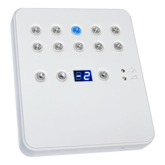
6 TOP FACE OF THE INTERFACE 19 : Mini USB connector (PC) / 5V. DC Scene triggering buttons: 20: Scene 1 On/Off 21: Scene 2 On/Off 22: Scene 3 On/Off 23: Scene 4 On/Off 24: Scene 5 On/Off 25: Scene 6 On/Off 26: Scene 7 On/Off 27: Scene 8 On/Off 28: Scene 9 On/Off 29: Scene 10 On/Off Command buttons: 30: Mode selection (trigger, speed, dimmer) 31: - decrease values 32: + increase values Display and LED: 33: Current mode LED 34: 7-segment LED display SELECTING MODE BUTTON Press the Mode button to select a mode between speed, dimmer or trigger LED 1 and 2 OFF : Trigger Mode. LED 1 ON only : Speed mode. LED 2 ON only : Dimmer mode. ( works on Dimmer or RGB channels) +/- BUTTONS OPERATION: Trigger mode: + and buttons allows to choose a different scene. You have to hold + and buttons for 2 seconds to validate the selection and play the new scene. Speed mode: + and buttons allows to increase or decrease the speed of the current scene from -9 to 9. Dimmer mode: + and buttons allows to increase or decrease the dimmer of the current scene from -9 to 9. LED 7-SEGMENTS DISPLAY OPERATION: Display the number of the playing scene and the mode (speed/dimmer) value. 00: Stand Alone mode running. No scene is playing. All DMX channels are set to 0. PC: The interface is connected to the computer and software controlled. In trigger mode, the 7 segment display gives the current scene number. The 00 value indicates that no scene is playing and the SLIM DMX interface send nulls (0x00) on all output DMX channels. In speed mode, the display indicates the speed of the current scene, values are between -9 and 9. In dimmer mode, the display indicates the general intensity, values are between -9 and 9. 5
7 LED 7-SEGMENTS SLEEP OPTION: It s possible to activate the sleep option in the software. This will turn off the display after 4 seconds of inactivity on the interface s buttons. Option available in the standalone window of the software EXTERNAL TRIGGERS OPERATION: Connect the pins to 5V following these combinations: 01 = A ; 02 = B ; 03 = AB ; 04 = C ; 05 = AC ; 06 = BC ; 07 = ABC ; 08 = D ; 09 = AD ; 10 = BD ; 11 = ABD ; 12 = CD ; 13 = ACD ; 14 = BCD ; 15 = ABCD. By default, the interface gives 4 external contacts (01, 02, 04, 08). To obtain 15 external contacts, you have to use a demultiplexing interface in order to go from 4 to 15 possible combinations. INFRA RED TRIGGERS OPERATION: An external module with an Infra Red receiver is necessary. It can be connected to the following pins: GND (pin 1 or 10) + 5V. DC out (pin 2) + IR Signal (pin 11). 6
8 INTERFACES MASTER/SLAVE CONNECTION When multiple interfaces are connected with USB, the standalone mode allows to set them as Master/Slave. This mode allows to synchronise many interfaces and mutualize their standalone spaces combining the universes. (up to 32 standalone universes ) A single interface can be define as master, others are automatically set to slaves. Triggers operated on the master interface are passed on slaves. However slaves are not synchronized on play time and keep individual control. Consequently slaves can trig and play different scenes. The master acts like a general remote imposing triggering to the slaves. Master/Slave mode allows to synchronize scenes and trigger actions of several interfaces together. To use interfaces as Master/Slave, you have to connect the interfaces each other s from the screw terminals. You need to connect together the pins M/S Data, M/S CLK and GND, as following: Interfaces configured as slave will strictly follow the clock, triggers and information providing by the master interface. Only one master interface at a time. 7

9 SETTING OF THE MASTER/SLAVE INTERFACES When multiple interfaces are connected with USB, the standalone mode allows to set them as Master/Slave. This mode allows to synchronize many interfaces and mutualize their standalone spaces combining the universes. (Up to 32 standalone universes) MODE MASTER/SLAVE «Default» The Stand Alone mode allows to choose 1 interface and to define this interface as Master from the interface list, it is possible to choose only one to be the Master, all the other one will be configured as slave by default. The interfaces are always ordered by serial number ascending order. A single interface can be define as master (lower serial number by default), others ones are automatically set to slaves. The master device play the current scene and synchronize the slave ones. The master forces the slave interfaces to play the same scene and the same step at the same time. The slave interfaces are forced to follow the master timings and triggers and they cannot act, play or trigger a scene independently. Master can trigger on and trigger off scenes of the slave interfaces. MODE MASTER/SLAVE «Desynchronized» An interface can be define as master, others are automatically set to slaves. All Triggers On or Off operated on the master interface are effective to slave ones. However slave interfaces are not synchronized with master's timing and keep individual controls. Consequently slaves can trigger and play different scenes at any time and not synchronized with the master ones. The master acts like a general remote imposing triggering to the slaves with total priority. Master can trigger ON and trigger OFF scenes of the slave interface. MODE MASTER/SLAVE «LTP» LTP means Latest Takes Priority. All interfaces are defined as slaves. Interfaces are not synchronized with timing and can trigger and play different scenes by itself. However triggers from an interface are passed to the others connected interfaces automatically and slave interfaces are forced to trigger the same scene. Here each interface acts like a general remote imposing triggering to the other slaves without synchronization. THE «NO RELEASE» Option This option is only available with LTP or DESYNCHRONIZED modes. Only triggers ON from the master interface are executed and effective. All triggers OFF are ignored and slaves interfaces keep playing their current scene. Each Slave interface can choose to release or not its scene depend on the option is activated or not. 8

10 DMX MERGING IN STANDALONE DMX Merging is available for the 1024 SLIM interfaces only, because it takes two DMX lines to make a merge. One DMX line must be turned into an input to capture the DMX signal provided by an external DMX board or by another DMX interface. The interface will merge the input signal with its own output signal by comparing DMX levels with a HTP filter. Merging is a solution to keep manual control on channels, using a DMX Board for example. It s also a way to create a multi-zones system by merging several interfaces on one final DMX line. DMX-B Must be turned into Input in the software Standard DMX Controller board The DMX Output is connected to the interface input LINE B mandatory DMX Output A is a merge between what the interface is playing and what is coming in the input line B. In the software s standalone window, select: DMX 1 OUT / DMX 2 IN and validate the merge option. 9

11 TRIGGERS CONFIGURATION WITH THE SOFTWARE The Stand Alone mode of the software enables to configure and personalize all the triggers. The information will be directly saved in the DMX interface memory with the memory writing function. SWITCH TO STANDALONE MODE When the device isn't connected to the software or has just been powered, it enters in Stand Alone mode after five (5) seconds. LED BUTTONS TRIGGER Standalone mode offers 10 buttons that represents the interface LED buttons. From the scene list of the standalone mode, you need to drag and drop a scene on any button to assign a button number. It's possible to replace a scene by another or to remove it by pulling it out of the list. INFRA RED REMOTE TRIGGERS Standalone mode offers up to 10 triggers with the Infra-Red remote. By selecting a scene in the list, it's possible to choose the remote button number (from 01 to 10) to trigger the scene. The other IR remote functions will work as well as the SLIM DMX interface. (Speed, dimmer, scene +, scene -, off). 10
 to trigger the scene. By default, the interface gives 4 external contacts (01, 02, 04, 08).")
12 EXTERNAL CONTACT TRIGGERS The Stand Alone mode offers up to 15 external possible triggers. By selecting a scene in the list, it's possible to choose the external contact number (from 01 to 15) to trigger the scene. By default, the interface gives 4 external contacts (01, 02, 04, 08). To obtain 15 external contacts, you have to use a demultiplexing interface in order to go from 4 to 15 possible combinations. DMX IN AND TRIGGERS VIA ANOTHER DMX SIGNAL The Stand Alone mode offers up to 512 DMX IN channel triggers and up to 255 DMX trigger values per channel. By selecting a scene in the list, it's possible to choose the channel number and the DMX value to trigger the scene. The scene will play when the value of the DMX channel is reached or exceeded. NOTE: This option is available with 1024 interfaces only One of the DMX lines must be turned into Input in software s options window. To reach this window go tu the software s menu : Tools > Options then click on the Device section as following : Device section Set DMX IN 11
13 TIME TRIGGERS WITH CLOCK AND CALENDAR The Stand Alone mode has an internal clock and a calendar. It's possible to assign a time trigger on every scene of the list. By selecting a scene on the list, it's possible to choose the start and end dates and hours and days of the week. You can thus create a lot of scenarios. CASE 1: Programming a unique trigger: Start schedule: The scene is triggered a single time at the given date and time. End schedule: The scene is stopped at the given date and time. CASE 2: Programming a repeating trigger: Start schedule: Date from which-one the scene will be playable according to the programmed triggers End schedule: Date after witch-one triggers will be ignored. With no End date, triggers are permanent 12
14 List of the months of the year The 12 check boxes represents the 12 months of the year (J) January to (D) December. The triggers will be performed on the activated months. Next, a daily hours range must be defined. Start and Stop days With a monthly repetition, you can choose the starting and stopping days for each chosen month. In this example triggers can happen between the 1 st and the 15 th of each chosen month. List of the days of the week The 7 check boxes represents the 7 days in a week. The triggers will be performed on the activated days only. Next, a time range must be defined. Start time The starting time is the time when the scene will be triggered for each chosen day. Of course chosen months, start and end schedule days are included. Release time The release time is the time when the scene will stop for each chosen day. Of course chosen months, start and end schedule days are included. The release time is not mandatory, if it s not defined, the scene will keep playing until another trigger event happens. (Like the triggering of another scene for example). NOTE: For a daily repetition, if the the starting time is later than the release time then the triggering will stopped the next day, even if the next day has not been selected. 13
15 SAVE AND RECOVER THE LAST SCENE AFTER THE POWER CUT OFF: Scenes with a start schedule and a stop schedule are set on a defined time space and can be memorized. The interface save the last scene played before the power cut off and recover it when the power is restored. The scene must obligatory include a start schedule and a stop schedule activate this option. SCENE TRIGGER PRIORITIES: When several scenes have the same time trigger (date + hour + minute), only the first scene in thelist will be triggered. The rest will be ignored 14


16 WALL MOUNTING INSTRUCTIONS The SLIM interface can we wall mounted on any place and surface. Wires are connected to the screw terminal block located on back of the SLIM housing. To fix the SLIM housing to a Europe, Asia or America standard wall switch box, there are 4 holes located behind the housing. Follow the mounting instruction to proceed. FOR EUROPE AND ASIA STANDARD: 60MM CENTER TO CENTER DISTANCE. FOR AMERICA STANDARD: 84MM CENTER TO CENTER DISTANCE. 15
, adjust the screw position to hold well the housing.")
17 BACK SIDE OF THE SLIM HOUSING SLIM Back side USA Wall switch Box USE THE SCREWS OF THE WALL SWITCH BOX TO OLD THE SLIM: 1 Insert the screws in the hole (vertical axe for USA wall boxes else horizontal axe ), adjust the screw position to hold well the housing. 2 Slide the housing to lock the screw in the slots 16
18 THE SECURE FIXING SLOT It's now easy to remove the SLIM from the wall by slinding it the oposit way to unlock the screws. To avoid and secure unexpected unlcoks, you can use the secure fixing slot. The secure fixing slot is use to ensure that housing stays on its wall mounted position. To do that it takes a special piece (plastic or metal) to be use like a lock. We do not provite this part. This piece size should be 15mm x 20 mm maximum and need to receive a screw. You also need to create a slot in the wall to receive that lock piece. Special lock piece (Not provided) Locked position Thanks to that lock, it's now not possible to slide back the switch box screws to the plain holes of the SLIM case. IMPOSIBLE TO SLIDE FROM POSITION 2 TO POSSION 1 17
Controlers. Controler
 s 4 INDEX Controlers Color Wheel LED Remote page 4 Push Button RGB Controler page 5 Dimmable LED Power Supplies page 6 DMX Controler Sunlite STICK 2 page 7 DMX Controler Sunlite STICK-GA2 page 8 DMX Controler
USER MANUAL V5.0 ST100
 GPS Vehicle Tracker USER MANUAL V5.0 ST100 Updated on 15 September 2009-1 - Contents 1 Product Overview 3 2 For Your Safety 3 3 ST100 Parameters 3 4 Getting Started 4 4.1 Hardware and Accessories 4 4.2
AC-115 Compact Networked Single Door Controller. Installation and User Manual
 AC-115 Compact Networked Single Controller Installation and User Manual December 2007 Table of Contents Table of Contents 1. Introduction...5 1.1 Key Features... 6 1.2 Technical Specifications... 7 2.
INSTALLATION MANUAL XM3 Reader
 INSTALLATION MANUAL XM3 Reader Conditions Transactions, deliveries et cetera will be according to the general terms of delivery as deposited at the Chamber of Commerce at Meppel, The Netherlands. Registration
Point of view HDMI Smart TV dongle Mini RF Keyboard
 Point of view HDMI Smart TV dongle Mini RF Keyboard English Contents Contents... 1 General notices for use... 2 Disclaimer... 2 Box Contents... 2 1. HDMI TV dongle... 3 1.1. Product display... 3 1.2. Instructions
The Foundation User Manual LED Battery Slim Par Fixture (RGBA, DMX 7Ch/4CH)
") The Foundation User Manual LED Battery Slim Par Fixture (RGBA, DMX 7Ch/4CH) Page 1 I. Security: 1. Make sure the user voltage cannot higher or lower than the regulating voltage. 2. Please use proper and
The Foundation User Manual LED Battery Slim Par Fixture (RGBA, DMX 7Ch/4CH) Page 1 I. Security: 1. Make sure the user voltage cannot higher or lower than the regulating voltage. 2. Please use proper and
AC612 XUB/XUF/DIN sidekick too
 AC612 XUB/XUF/DIN sidekick too 512 channel houselight / architectural controller and universal wing Users Manual for Software version 2.05 Including Editor Software AC 612 XU and sidekick too The AC612
BMW CAR-PC MONITOR MODEL SPECIFICATION BMW3/5 SERIES. Model Name : BMW-100P Paper Version : Ver 1.0
 BMW CAR-PC MONITOR MODEL SPECIFICATION BMW3/5 SERIES Model Name : BMW-100P Paper Version : Ver 1.0 INDEX Precacution Specification System Composition Product Outline Connector Pin Assignment Installaion
TCP/IP MODULE CA-ETHR-A INSTALLATION MANUAL
 TCP/IP MODULE CA-ETHR-A INSTALLATION MANUAL w w w. c d v g r o u p. c o m CA-ETHR-A: TCP/IP Module Installation Manual Page Table of Contents Introduction...5 Hardware Components... 6 Technical Specifications...
2-Port RS232/422/485 Combo Serial to USB2.0 Adapter (w/ Metal Case and Screw Lock Mechanism) Installation Guide
 Installation Guide") 2-Port RS232/422/485 Combo Serial to USB2.0 Adapter (w/ Metal Case and Screw Lock Mechanism) Installation Guide 1. Introduction Thank you for purchasing this 2-Port RS232/422/485 Combo Serial to USB Adapter.
2-Port RS232/422/485 Combo Serial to USB2.0 Adapter (w/ Metal Case and Screw Lock Mechanism) Installation Guide 1. Introduction Thank you for purchasing this 2-Port RS232/422/485 Combo Serial to USB Adapter.
LED BAR 126 / 252 RGB. Owner s Manual LED BAR RGB
 LED BAR 126 / 252 RGB Owner s Manual LED BAR RGB Thank you for choosing one of our LED bars. Please read this user manual carefully and follow the instructions to avoid danger or damage to the unit due
16-Port RS232 to USB2.0 High Speed Multi Serial Adapter (w/ Metal Case) Installation Guide
 Installation Guide") 16-Port RS232 to USB2.0 High Speed Multi Serial Adapter (w/ Metal Case) Installation Guide 1. Introduction Thank you for purchasing this 16-Port RS232 to USB2.0 High Speed Multi Serial Adapter. It is an
16-Port RS232 to USB2.0 High Speed Multi Serial Adapter (w/ Metal Case) Installation Guide 1. Introduction Thank you for purchasing this 16-Port RS232 to USB2.0 High Speed Multi Serial Adapter. It is an
LED WALL WASHERS SPECIFICATIONS & INSTALLATION GUIDE
 LED WALL WASHERS SPECIFICATIONS & INSTALLATION GUIDE ContenTS: Brief specifications LED WALL WASHER WWF 12 48... 4 LED WALL WASHER WWB 14 36... 5 LED WALL WASHER WWS 16 12... 6 LED WALL WASHER WWS 32 24...
Technical data. General specifications. Indicators/operating means. 30 Hz Multiplex operation 30 Hz / n, n = number of sensors, n 5
 Model Number Single head system Features Parameterization interface for the application-specific adjustment of the sensor setting via the service program ULTRA 000 programmable switch outputs Hysteresis
Model 201 Wiegand Touchpad Reader Installation Guide
 Model 201 Wiegand Touchpad Reader Installation Guide P/N 460353001C 15AUG11 2011 UTC Fire & Security. All rights reserved. This document may not be copied in whole or in part or otherwise reproduced without
19 LED Tube Controller ORDERCODE 41003
 19 LED Tube Controller ORDERCODE 41003 Congratulations! You have bought a great, innovative product from Showtec. The Showtec 19 LED Tube Controller brings excitement to any venue. Whether you want simple
OVERVIEW Playbacks: Shortcuts: Memories: Data Entry Wheels: Touchpad: Master and Blackout:
 OVERVIEW The MIDIcon is a USB MIDI control panel designed to work alongside the Elation lighting software packages. The Midicon is USB powered and uses the USB class drivers so that no driver needs to
Inwall 4 Input / 4 Output Module
 Inwall 4 Input / 4 Output Module IO44C02KNX Product Handbook Product: Inwall 4 Input / 4 Output Module Order Code: IO44C02KNX 1/27 INDEX 1. General Introduction... 3 2. Technical data... 3 2.1 Wiring Diagram...
COLOR TFT LCD MONITOR. User Manual
 COLOR TFT LCD MONITOR User Manual GENERAL INFORMATION Thank you for choosing our TFT LCD(liquid crystal display) monitor. This product employs integrate circuits, low power consumption, and no radiation
The RIDZ 8x2 Audio Switcher
 The RIDZ 8x2 Audio Switcher Engineering Manual Support Number 800-765-2930 International 712-852-2813 Table of Contents General Information for the RIDZ (8 x 2) Switcher..... 3 Input 9 on the RIDZ Switcher....6
Series. Laser air Leddura Lexinus Mensa. 70 inch. Smart innovation! When function matters.
 Leddura Lexinus Mensa Series When function matters. High quality displays suitable for all applications. Stay connected to your audience via the built-in wireless access point for a productive and collaborative
Analogue Input, 4-fold, MDRC AE/S 4.1, GH Q605 0054 R0001
 Analogue Input, -fold, MDRC, GH Q605 005 R0001 The analogue input is a DIN rail mounted device for insertion in the distribution board. It is connected to the EIB via the bus connecting terminal supplied.
KNX Gateway RGK02-5023E-01
 KNX Gateway RGK02-5023E-01 Table of contents Page 1 General Information 1.1 Technical data 5 1.2. Intended Use 6 1.3 Specifications 6 1.4 Compatibility 6 1.5 Scope of delivery 6 2 Information about the
IntesisBox KNX Mitsubishi Heavy Industries AC
 IntesisBox KNX Mitsubishi Heavy Industries AC Gateway for integration of Mitsubishi Heavy Indsutries (MHI) Air Conditioners with KNX control systems. 1. Main Features Direct connection to KNX TP-1 (EIB)
PCS300 Universal IP Reporting Module V1.0
 PCS300 Universal IP Reporting Module V1.0 Reference and Installation Manual Patents: One or more of the following US patents may apply: 7046142, 6215399, 6111256, 6104319, 5920259, 5886632, 5721542, 5287111,
PRELIMINARY MANUAL STAGE COLOR 48. Preliminary User Guide. Official version will follow soon on: WWW.BRITEQ-LIGHTING.COM TABLE OF CONTENTS
 STGE COO 48 Preliminary User Guide Official version will follow soon on: WWW.BITEQ-IGHTIG.COM TBE OF COTETS 1. Safety Instruction 2. Technical Specification 3. How To Set The Unit 4. How To Control The
PU-USBX. USB over Ethernet Extender OPERATION MANUAL
 PU-USBX USB over Ethernet Extender OPERATION MANUAL Safety Precautions Please read all instructions before attempting to unpack or install or operate this equipment, and before connecting the power supply.
Data logger. Installation and operating instructions. Read carefully before installation, commissioning and operation.
 Data logger Installation and operating instructions SOREL Connect Read carefully before installation, commissioning and operation 1.1. - Specifications Description of data logger Electrical specifications:
SCD Server. SCD Server Pro
 SCD Server SCD Server Pro SCD Server & SCD Server Pro 9850-000387-01 - Page 1 of 8 SCD Server and SCD Server Pro The SCD Server is a 2U high DMX generator, running the ZerOS Operating System and emulating
UniPi technical documentation REV 1.1
 technical documentation REV 1.1 Contents Overview... 2 Description... 3 GPIO port map... 4 Power Requirements... 5 Connecting Raspberry Pi to UniPi... 5 Building blocks... 5 Relays... 5 Digital Inputs...
Switch Actuator, 8-fold, 10 A, MDRC AT/S 8.10.1, GH Q631 0075 R0111
 , GH Q631 0075 R0111 The 8-fold switch actuator is a DIN rail mounted device for insertion in the distribution board. It is connected to the EIB via a bus terminal. In the event of bus voltage failure,
3.5 Dual Bay USB 3.0 RAID HDD Enclosure
 3.5 Dual Bay USB 3.0 RAID HDD Enclosure User Manual August 11, 2011 v1.1 MFG Part # MT2U3-MP BARCODE Introduction 1 Introduction 1.1 System Requirements 1.1.1 PC Requirements Minimum Intel Pentium III
Operating instructions Diffuse reflection sensor. OJ50xx 701396 / 01 07 / 2004
 Operating instructions Diffuse reflection sensor OJ50xx 7096 / 0 07 / 004 Contents Preliminary note. Symbols used Function and features Installation. Installation of the supplied mounting fixture 4 4 Electrical
DOMUSBOX. User guide. Index
 DOMUSBOX User guide Index Introduction... 2 1. Installing SEAV DOMUS... 4 1.1 Activating DomusBox... 4 1.2Drawing the environments in DomusWeb... 5 1.3Connecting DomusBox to the devices...9 1.4Configuration
JNIOR. Overview. Get Connected. Get Results. JNIOR Model 310. JNIOR Model 312. JNIOR Model 314. JNIOR Model 410
 The INTEG is an Ethernet I/O (digital, analog) device that monitors and controls a small set of process signals. functions as both basic I/O for integration with another application or system AND as a
Install the DeviceNet Module using the following procedure:
 Installation INSTALLATION INSTRUCTIONS: MCD DEVICENET MODULE Order Code: 175G9002 1. Installation Install the DeviceNet Module using the following procedure: 1. Remove control power and mains supply from
LGAC-KNX PROGRAMMING MANUAL. Integrations V1.0 TECHNICAL SUPPORT. Tel (+34) 985 113 339 tecnico@ingeniumsl.com
 985 113 339 tecnico@ingeniumsl.com") Integrations LGAC-KNX V1.0 PROGRAMMING MANUAL Parque Tecnológico de Asturias, Parcela 50, 33428 Llanera Asturias - Spain Tel (+34) 985 118 859 Fax (+34) 984 283 560 ingeniumsl@ingeniumsl.com www.ingeniumsl.com
Integrations LGAC-KNX V1.0 PROGRAMMING MANUAL Parque Tecnológico de Asturias, Parcela 50, 33428 Llanera Asturias - Spain Tel (+34) 985 118 859 Fax (+34) 984 283 560 ingeniumsl@ingeniumsl.com www.ingeniumsl.com
Product and Applications Description. Application Programs. Example of Operation. GAMMA instabus Technical Product-Information.
 Product and Applications Description The power supply units N 125/x2 can supply DC 24 V power from an additional pair of terminals (yellowwhite). This DC 24 V output voltage can be used to power e.g. an
CX Series. Video Recording Server. Quick Start Guide CX784 / CX788 / CX7816. Version 1.05.00
 CX Series Video Recording Server CX784 / CX788 / CX7816 Quick Start Guide Version 1.05.00 Contents 1.Introduction...1 1.1.Packages Contents...1 1.2.Hardware Features...2 1.3.Functional Features...4 1.4.Hard
Controller board and power supply for vivimat III systems
 Controller board and power supply for vivimat III systems Ref: VIVIMAT-3.0 The controller board and power supply vivimat 3.0, is the central core of the vivimat III home automation system. The vivimat
PCS0100en 02.2008. Persy Control Services B.V. Netherlands
 P-Bus Gateway PBGW2.128 Universal gateway between the P-bus protocol and open standard protocols. The variety of available electrical interfaces on the gateway offers a wide range of possibilities for
How To Power A Power Control On An Ip40 (Ipl) With A Power Supply (Iplug) With An Ip20 Controller (Iphones) With Power Control (Power Control) With No Antenna) With The Ip20 (Power)
 With A Power Supply (Iplug) With An Ip20 Controller (Iphones) With Power Control (Power Control) With No Antenna) With The Ip20 (Power)") MODEL NUMBER: ISC910-1-0-GB-XX ISC911-5-0-GB-XX IXP20 CONTROLLER SPECIFICATIONS Working Environment Plastic Housing... Power ImproX IXP20 Controller INSTALLATION MANUAL Designed to work in an indoor (dry)
MODEL NUMBER: ISC910-1-0-GB-XX ISC911-5-0-GB-XX IXP20 CONTROLLER SPECIFICATIONS Working Environment Plastic Housing... Power ImproX IXP20 Controller INSTALLATION MANUAL Designed to work in an indoor (dry)
How to read this guide
 How to read this guide The following shows the symbols used in this Quick start guide with descriptions and examples. Symbol Description Example P oint Reference Caution [ ] This symbol explains information
PART 1 PRODUCT (GENERAL)...1.
...1.") 11 T ABLE OF CONTENTS PART 1 PRODUCT (GENERAL)...1. 1.1--PRODUCT INTRODUCTION...1. 1.2--PRODUCT FEATURES...1. 1.3--TECHNICAL SPECIFICATIONS...2. 1.4--PHOTOMETRIC DATA...3. 1.5--SAFETY WARNING...4. PART
11 T ABLE OF CONTENTS PART 1 PRODUCT (GENERAL)...1. 1.1--PRODUCT INTRODUCTION...1. 1.2--PRODUCT FEATURES...1. 1.3--TECHNICAL SPECIFICATIONS...2. 1.4--PHOTOMETRIC DATA...3. 1.5--SAFETY WARNING...4. PART
3x cinch/s-video socket Order no.: 33 1532 xx. USB/3.5 mm audio socket Order no.: 33 1539 xx. VGA socket Order no.: 33 1540 xx
 3x cinch/s-video socket Order no.: 33 1532 xx USB/3.5 mm audio socket Order no.: 33 1539 xx VGA socket Order no.: 33 1540 xx VGA socket with screw-in lift terminals Order no.: 33 1541 xx High definition
T O K I S T A R L I G H T I N G I N S T R U C T I O N M A N U A L LC-1CH-MULTI Dimmer Module
 T O K I S T A R L I G H T I N G I N S T R U C T I O N M A N U A L Dimmer Module General The Dimmer Pack can be used with any of Tokistar s LED Lighting Systems operating from our 6, 8 or VDC LED Drivers.
UPS PIco. to be used with. Raspberry Pi B+, A+, B, and A. HAT Compliant. Raspberry Pi is a trademark of the Raspberry Pi Foundation
 UPS PIco Uninterruptible Power Supply with Peripherals and I 2 C control Interface to be used with Raspberry Pi B+, A+, B, and A HAT Compliant Raspberry Pi is a trademark of the Raspberry Pi Foundation
I STAR COMPUTER CO., LTD
 I STAR COMPUTER CO., LTD Mini Redundant Power Supply 300W+300W for IPC-Computer Model No. TC-300R8 Table of content 1. Introduction...1 2. Specification 2.1 Input Voltage...1 2.2 DC Output...1 2.3 PS-ON
INDEX. Trademarks All name and product s trademarks mentioned below are the property of their respective companies.
 USB2.0 EASY IDE ADAPTER INDEX Trademarks ---------------------------------------------------------------------------- Introduction ---------------------------------------------------------------------------
VIDEO DOOR PHONE SYSTEM
 ENGLISH VIDEO DOOR PHONE SYSTEM USER MANUAL Manual covers IH-692 Master and IH-692 Slave Monitors PRECAUTIONS BEFORE INSTALLATION Connect this unit ONLY to other compatible units. Do not connect it to
EasyMP Multi PC Projection Operation Guide
 EasyMP Multi PC Projection Operation Guide Contents Introduction to EasyMP Multi PC Projection... 7 EasyMP Multi PC Projection Features... 7 Connection to Various Devices... 7 Four-Panel Display... 8
Quick Start Guide. DVR DS-7200HWI-SH Series DVR. www.hikvision.com. First Choice For Security Professionals
 Quick Start Guide DVR DS-7300HWI-SH Series DVR DS-7200HWI-SH Series DVR NOTE: For more detailed information, refer to the User s Manual on the CD-ROM. You must use your PC or MAC to access the files. www.hikvision.com
ACR120 Technical Specifications version 2.9 November 2005
 Version 2.9 11-2005, Email: info@acs.com.hk Website: www.acs.com.hk ACR120 Contactless Reader/Writer 1.0 Introduction The ACR120 is a compact and cost-effective contactless reader and writer. It is developed
OZW30. Central Unit SYNERGYR
 2 841 SYNERGYR Central Unit OZW30 Collects billing data from the apartments. Generates an image of each apartment's heat consumption and makes it available for readout. Acts on room temperature control
GSM Autodialer Professional GJD700 Speech & Text Autodialer
 Text Edit message GSM Autodialer Professional GJD700 Speech & Text Autodialer Introduction The GSM Autodialer Professional works in conjunction with standard alarm systems and makes use of your preferred
MAGICAR M871A. Car alarm with two-way remote User s guide
 MAGICAR M871A Car alarm with two-way remote User s guide EN MAGICAR M871A Car alarm with two-way remote User s guide TABLE OF CONTENTS Table of contents...2 1. Important notice...4 2. Introduction...4
MANUAL PC1000R INFO@APART-AUDIO.COM
 MANUAL PC1000R INFO@APART-AUDIO.COM Features The APart PC1000R is a professional multisource CD/USB/SD card music player, equipped with balanced and unbalanced analog outputs, coaxial and optical digital
USB to RS-422/485 Serial Adapter
 USB to RS-422/485 Serial Adapter User Manual Ver. 2.00 All brand names and trademarks are properties of their respective owners. Contents: Chapter 1: Introduction... 3 1.1 Product Introduction... 3 1.2
is605 Dual-Bay Storage Enclosure for 3.5 Serial ATA Hard Drives FW400 + FW800 + USB2.0 Combo External RAID 0, 1 Subsystem User Manual
 is605 Dual-Bay Storage Enclosure for 3.5 Serial ATA Hard Drives FW400 + FW800 + USB2.0 Combo External RAID 0, 1 Subsystem User Manual (English/Deutsch/ 中 文 ) v1.0 August 23, 2007 Table of Contents CHAPTER
FUSION R400 RAID USB 3.0
 FUSION R400 RAID USB 3.0 1U Rackmount 4-Drive Hardware RAID 5 SATA Storage System with USB 3.0 Interface User s Guide For Windows Contents 1 Fusion R400 RAID USB 3.0 Features 1 2 Drive Installation and
User s Guide DDS-3X25 USB ARBITRARY FUNCTION GENERATOR
 User s Guide DDS-3X25 USB ARBITRARY FUNCTION GENERATOR Content General safety summary...1 Introduction...2 Chapter 1 Getting started...3 System Requirements...4 Installing Hardware...5 Installing Software...8
CNC-STEP. "LaserProbe4500" 3D laser scanning system Instruction manual
 LaserProbe4500 CNC-STEP "LaserProbe4500" 3D laser scanning system Instruction manual 2 Hylewicz CNC-Technik Siemensstrasse 13-15 D-47608 Geldern Fon.: +49 (0) 2831 133236 E-Mail: info@cnc-step.com Website:
Smarthome SELECT Bluetooth Wireless Stereo Audio Receiver and Amplifier INTRODUCTION
 Smarthome SELECT Bluetooth Wireless Stereo Audio Receiver and Amplifier INTRODUCTION The Smarthome SELECT Bluetooth Wireless Stereo Audio Receiver and Amplifier is a multi-functional compact device. It
e-4 AWT07MLED 7 Q TFT LCD MONITOR (LED Backlighted) USER MANUAL
 USER MANUAL") Thank you for purchasing our product. Please read this User s Manual before using the product. Change without Notice AWT07MLED 7 Q TFT LCD MONITOR (LED Backlighted) USER MANUAL e-4 SAFETY PRECAUTIONS Federal
Thank you for purchasing our product. Please read this User s Manual before using the product. Change without Notice AWT07MLED 7 Q TFT LCD MONITOR (LED Backlighted) USER MANUAL e-4 SAFETY PRECAUTIONS Federal
Bluetooth HC-06 with serial port module Easy guide
 1 Bluetooth HC-06 with serial port module Easy guide This manual consists of 3 parts: PART 1. Overview of Bluetooth HC-06 module with serial port. PART 2. Installing Bluetooth HC-06 module with Bolt 18F2550
How to setup a serial Bluetooth adapter Master Guide
 How to setup a serial Bluetooth adapter Master Guide Nordfield.com Our serial Bluetooth adapters part UCBT232B and UCBT232EXA can be setup and paired using a Bluetooth management software called BlueSoleil
PART 1 PRODUCT (GENERAL)...1.
...1.") TABLE OF CONTENTS PART 1 PRODUCT (GENERAL)...1. 1.1--PRODUCT INTRODUCTION...1. 1.2--PRODUCT FEATURES...1. 1.3--TECHNICAL SPECIFICATIONS...2. 1.4--PHOTOMETRIC DATA...3. 1.5--SAFETY WARNING...4. PART 2 INSTALLATION...5.
TABLE OF CONTENTS PART 1 PRODUCT (GENERAL)...1. 1.1--PRODUCT INTRODUCTION...1. 1.2--PRODUCT FEATURES...1. 1.3--TECHNICAL SPECIFICATIONS...2. 1.4--PHOTOMETRIC DATA...3. 1.5--SAFETY WARNING...4. PART 2 INSTALLATION...5.
SYSTEM 4C. C R H Electronics Design
 SYSTEM 4C C R H Electronics Design SYSTEM 4C All in one modular 4 axis CNC drive board By C R Harding Specifications Main PCB & Input PCB Available with up to 4 Axis X, Y, Z, A outputs. Independent 25
Multi-function Front Panel USB2.0/Firewire 400/eSATA
 Multi-function Front Panel USB2.0/Firewire 400/eSATA Model No.: UGT-IH100 Installation Guide v1.01 1 Prescribed Use The UGT-IH100 is designed to be installed into the 3.5 or 5.25 plug-in unit of a computer
Mounting HP Desktop Mini Rack Mount Tray Kit HP Desktop Mini Security/Dual VESA Sleeve
 Mounting HP Desktop Mini Rack Mount Tray Kit HP Desktop Mini Security/Dual VESA Sleeve Optical Drive HP Desktop Mini DVD Super Multi-Writer ODD Expansion Module Input / Output / HDD HP Desktop Mini 500GB
GV- RK1352 Card Reader
 GV- RK1352 Card Reader The GV-RK1352 is a card reader with keypad, designed to recognize PIN codes, identification cards or both. Featured with the Wiegand and RS-485 outputs, the unit can be connected
ZME_05459 Wall Blind Control Set for Busch-Jaeger DURO 2000 Firmware Version : 1.8
 ZME_05459 Wall Blind Control Set for Busch-Jaeger DURO 2000 Firmware Version : 1.8 Quick Start A This device is a Z-Wave Actuator. Triple click one of the buttons on the device will include the device.
Taurus Super-S3 LCM. Dual-Bay RAID Storage Enclosure for two 3.5-inch Serial ATA Hard Drives. User Manual March 31, 2014 v1.2 www.akitio.
 Dual-Bay RAID Storage Enclosure for two 3.5-inch Serial ATA Hard Drives User Manual March 31, 2014 v1.2 www.akitio.com EN Table of Contents Table of Contents 1 Introduction... 1 1.1 Technical Specifications...
Version Date Author Description 1.00 19.07.2010 Jpo First version 1.01 21.12.2010 Jpo FET output descriptions made clearer 1.02 04.02.
 +3 # Version Date Author Description 1.00 19.07.2010 Jpo First version 1.01 21.12.2010 Jpo FET output descriptions made clearer 1.02 04.02.2011 Jpo Reset button added 1. Purpose of this user manual...
Sympodium Interactive Pen Display
 Physical Specifications Sympodium Interactive Pen Display Specifications Model DT770 Size Display Area Weight Shipping Size Shipping Weight (Carton and Contents) 19" W 18" H 3 5/8" D (48.3 cm 45.7 cm 9.2
SYSTEM 45. C R H Electronics Design
 SYSTEM 45 C R H Electronics Design SYSTEM 45 All in one modular 4 axis CNC drive board By C R Harding Specifications Main PCB & Input PCB Available with up to 4 Axis X, Y, Z, & A outputs. Independent 25
1. Introduction... 3. 2.Fixture exterior view... 3. 3. Connecting the Robe Universal Interface... 4. 3.1 Software update of the fixture...
 1 Table of contests 1. Introduction... 3 2.Fixture exterior view... 3 3. Connecting the Robe Universal Interface... 4 3.1 Software update of the fixture... 4 3.2 Connecting a DMX console to the Media Fusion...
Business/Home GSM Alarm System. Installation and User Manual
 Business/Home GSM Alarm System Installation and User Manual Brief Introduction: GSM 900/1800/1900 bands, can be used in most parts of the world Full duplex communication with the host Monitor the scene
USER MANUAL. KIT VIDEO DOOR PHONE 2 smart 1 family
 USER MANUAL EN KIT VIDEO DOOR PHONE smart 1 family Harry Johnston Call from the outdoor panel keys; Possibility to see on the terminal's display the person calling ; Duplex hands-free audio communication;
DVB-T 730. User s Manual
 EPG Program Reservation There are 10 program timers to bring up reminder for a reserved program. 20 seconds before the start of the reserved program, a pop-up window will remind viewer. If no further instruction,
ACR880 GPRS Portable Smart Card Terminal
 ACR880 GPRS Portable Smart Card Terminal Technical Specifications Subject to change without prior notice Table of Contents 1.0. Introduction... 3 2.0. Features... 4 3.0. Supported Card Types... 5 3.1.
Taurus - RAID. Dual-Bay Storage Enclosure for 3.5 Serial ATA Hard Drives. User Manual
 Dual-Bay Storage Enclosure for 3.5 Serial ATA Hard Drives User Manual v1.0 August 23, 2007 EN Table of Contents CHAPTER 1 - INTRODUCTION 1 CHAPTER 3 - SYSTEM SET UP 9 ICON KEY 1 THE TAURUS RAID 1 AVAILABLE
7x10W 4IN1 Indoor Par Light User Manual
 7x10W 4IN1 Indoor Par User Manual Introduction Welcome to use High Power 4IN1 Indoor LED PAR under Neo-Neon Brand, This fixture applies high power LED technology and enjoys long life span. It can work
How To Use An Easymp Network Projector On A Computer Or Network Projection On A Network Or Network On A Pc Or Mac Or Ipnet On A Laptop Or Ipro Or Ipo On A Powerbook On A Microsoft Computer On A Mini
 EasyMP Network Projection Operation Guide Contents 2 Before Use Functions of EasyMP Network Projection....................... 5 Sharing the Projector....................................................
Connect to a remote PC via Ethernet with a monitor, keyboard, and mouse. This network monitor offers both long distance and wireless transmission.
 17" (43 cm) LCD Monitor Connect to a remote PC via Ethernet with a monitor, keyboard, and mouse. This network monitor offers both long distance and wireless transmission. Long Distance Transmission Easily
User Manual. AS-Interface Programmer
 AS-Interface Programmer Notice: RESTRICTIONS THE ZMD AS-INTERFACE PROGRAMMER HARDWARE AND ZMD AS-INTERFACE PROGRAMMER SOFTWARE IS DESIGNED FOR IC EVALUATION, LABORATORY SETUP AND MODULE DEVELOPMENT ONLY.
TRIMBLE TX5 3D LASER SCANNER QUICK START GUIDE
 TRIMBLE TX5 3D LASER SCANNER QUICK START GUIDE Equipment 1 8 9 5 6 7 4 3 2 The TX5 laser scanner ships with the following equipment: 1 Scanner transport and carry case 6 USB memory card reader 2 AC power
User Manual. Air-conditioner Controller SB-DN-HVAC (MAC01.331) www.hdlautomation.com
 www.hdlautomation.com") Air-conditioner Controller SB-DN-HVAC (MAC01.331) www.hdlautomation.com Document updates: Version Data Description V1.0 2015.05.25 Finish new document HVAC Controller User Manual INDEX 1. Overview...1
Air-conditioner Controller SB-DN-HVAC (MAC01.331) www.hdlautomation.com Document updates: Version Data Description V1.0 2015.05.25 Finish new document HVAC Controller User Manual INDEX 1. Overview...1
How To Use A Pkn10 (Powerline) With A Microsd Card (Powerkit) On A Powerline (Powergen) Or Powerline 2 (Powerbee) (Powerbmi) (Pk10) (Operating
 With A Microsd Card (Powerkit) On A Powerline (Powergen) Or Powerline 2 (Powerbee) (Powerbmi) (Pk10) (Operating") GB PKN10 serial node with colour LCD display User s manual Bač 49a, 6253 Knežak, SLOVENIA tel: ++ 386 5 753 2006 fax: ++ 386 5 753 2007 email: sec.electronics@siol.net http://www.secelectro.com SEC Electronics
GB PKN10 serial node with colour LCD display User s manual Bač 49a, 6253 Knežak, SLOVENIA tel: ++ 386 5 753 2006 fax: ++ 386 5 753 2007 email: sec.electronics@siol.net http://www.secelectro.com SEC Electronics
Business Audio System: Music & Messaging MP3 Player. by Grace Digital Audio. User Guide. Model No. GDI-USBM10
 Business Audio System: Music & Messaging MP3 Player by Grace Digital Audio User Guide Model No. GDI-USBM10 User Guide Contents Introduction 2 Safety & General Use Information 2 Features 3 Set Up & Operation
Table of Contents. Hardware Installation...7 Push Button Security... 8. Using the Setup Wizard...10. Configuration...11 Main... 12 Security...
 Table of Contents Table of Contents Product Overview...3 Package Contents...3 System Requirements... 3 Introduction...4 Features... 4 Hardware Overview...5 LEDs... 5 Connection... 6 Hardware Installation...7
Duct Humidity Transmitter
 SDC-H Duct Humidity Transmitter Features Replaceable sensor element Humidity measurement for air ducts Minimum and maximum value memory 0 0V, 0 0mA or 0V, 4 0mA measuring signals selectable with jumpers
Bluetooth to Serial Adapter
 Bluetooth to Serial Adapter Third Edition, Oct 2007 Version 3.0 771-BTS1009C3-001 Contents 1.0 Features....P.2 2.0 Package Content....P.2 3.0 Hard Drives Requirement.P.2 4.0 Specifications.P.3 5.0 Pin
Comparison SMART Board Interactive Whiteboard Systems. Models SB600i2, SB600i3 and SB685ix
 PLEASE THINK BEFORE YOU PRINT Comparison SMART Board Whiteboard Systems Models SB600i2, SB600i3 and SB685ix A SMART Board interactive whiteboard system comprises an interactive whiteboard, a wall-mounted
Neo-Neon. LED Vision Mesh Screen Operation Manual. LED Vision Mesh Screen. Neo-Neon International Ltd He Shan Decorative Lighting Company Limited
 Neo-Neon LED Vision Mesh Screen Operation Manual He Shan Decorative Lighting Company Limited LED Display Engineering Department 1 Contents Chapter1 Specification and Function Parameters 3 Chapeter2 Structure
Technical description MX-1 VB Edge
 1 (7) Technical description MX-1 VB Edge 2 (7) Table of Contents 1 General description...3 2 Connectors...4 3 ON/OFF operation...5 4 Power...5 5 LED indicators...6 6 Enclosure...6 7 Mounting...6 8 and
RGB Light Panel Applications. RGB LED Light Panel FEATURES & BENEFITS SPECIFICATION SHEET
 RGB LED Light Panel E346146 E325925 FEATURES & BENEFITS AVAILABLE IN CUSTOM SIZES & SHAPES CAN BE USED IN FRAMELESS DESIGNS 3D V-CUTTING TECHNOLOGY MULTI-COLOR OPTION HIGH BRIGHTNESS (2,000-10,000 LUX)
Adaptability to Enhanced Security
 Installer Guide Adaptability to Enhanced Security AdapTec Plus combines power supply and door access controller features in a compact casing for an encrypted and secure I/O function, enhancing door access
Bluetooth + USB 16 Servo Controller [RKI-1005 & RKI-1205]
![Bluetooth + USB 16 Servo Controller [RKI-1005 & RKI-1205]](/thumbs/40/21161302.jpg "Bluetooth + USB 16 Servo Controller [RKI-1005 & RKI-1205]") Bluetooth + USB 16 Servo Controller [RKI-1005 & RKI-1205] Users Manual Robokits India info@robokits.co.in http://www.robokitsworld.com Page 1 Bluetooth + USB 16 Servo Controller is used to control up to
Bluetooth + USB 16 Servo Controller [RKI-1005 & RKI-1205] Users Manual Robokits India info@robokits.co.in http://www.robokitsworld.com Page 1 Bluetooth + USB 16 Servo Controller is used to control up to
ETHERNET IRRIGATION CONTROLLER. Irrigation Caddy Model: ICEthS1. User Manual and Installation Instructions
 ETHERNET IRRIGATION CONTROLLER Irrigation Caddy Model: ICEthS1 User Manual and Installation Instructions I R R I G A T I O N C A D D Y M O D E L : I C E T H S 1 User Manual and Installation Instructions