FCC EMC Test Report. (Verification of Conformity) For. Electromagnetic Interference. Prepared for FINGERTEC WORLDWIDE SDN BHD.
|
|
|
- Austen Daniel
- 7 years ago
- Views:
Transcription
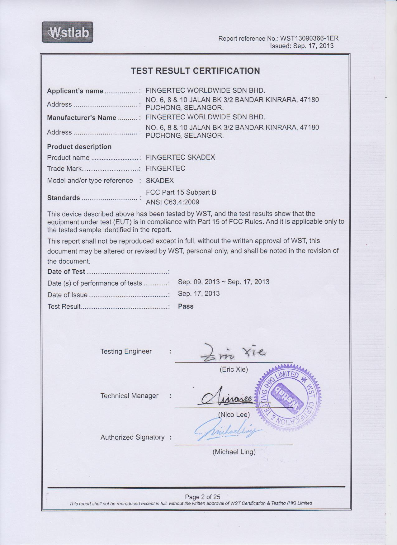
1 FCC EMC Test Report (Verification of Conformity) For Electromagnetic Interference Of Product: FINGERTEC SKADEX Trade Name: FINGERTEC Model Number: SKADEX Prepared for FINGERTEC WORLDWIDE SDN BHD. NO. 6, 8 & 10 JALAN BK 3/2 BANDAR KINRARA, PUCHONG, SELANGOR. Prepared by WST Certification & Testing (HK) Limited 12/F., San Toi Building, Connaught Road Central, Hong Kong Tel: (00852) Fax: (00852) Shenzhen office: Tel: Fax: Website: Page 1 of 25
2
3 1. TEST SUMMARY TEST FACILITY MEASUREMENT UNCERTAINTY 5 2. GENERAL INFORMATION GENERAL DESCRIPTION OF EUT DESCRIPTION OF TEST MODES DESCRIPTION OF TEST SETUP DESCRIPTION TEST PERIPHERAL AND EUT PERIPHERAL MEASUREMENT INSTRUMENTS LIST EMC EMISSION TEST CONDUCTED EMISSION MEASUREMENT POWER LINE CONDUCTED EMISSION TEST PROCEDURE TEST SETUP EUT OPERATING CONDITIONS TEST RESULTS RADIATED EMISSION MEASUREMENT LIMITS OF RADIATED EMISSION MEASUREMENT TEST PROCEDURE TEST SETUP EUT OPERATING CONDITIONS TEST RESULTS TEST RESULTS(Above 1GHz) EUT TEST PHOTO 20 ATTACHMENT PHOTOGRAPHS OF EUT 22 Page 3 of 25
4 1. TEST SUMMARY Test procedures according to the technical standards: EMC Emission Standard Test Item Limit Judgment Remark FCC Part 15 Subpart B Conducted Emission Class B PASS ANSI C63.4:2009 Radiated Emission Class B PASS NOTE: (1) N/A denotes test is not applicable in this Test Report (2) For client s request and manual description, the test will not be executed. Page 4 of 25
5 1.1 TEST FACILITY WST Certification & Testing (HK) Limited Add. : 12/F., San Toi Building, Connaught Road Central, Hong Kong 1.2 MEASUREMENT UNCERTAINTY The reported uncertainty of measurement y ± U,where expended uncertainty U is based on a standard uncertainty multiplied by a coverage factor of k=2,providing a level of confidence of approximately 95 %. A. Conducted Measurement : Test Site Method Measurement Frequency Range U,(dB) NOTE WSTC01 ANSI 150 KHz ~ 30MHz 3.2 B. Radiated Measurement : Test Site Method Measurement Frequency Range U,(dB) NOTE WSTA01 ANSI 30MHz ~ 1000MHz 4.7 Page 5 of 25
6 2. GENERAL INFORMATION 2.1 GENERAL DESCRIPTION OF EUT Equipment Model Name Serial No Model Difference FINGERTEC SKADEX SKADEX N/A N/A The EUT is a FINGERTEC SKADEX Product Description Power Source Power Rating Operating frequency: Connecting I/O port: N/A N/A Based on the application, features, or specification exhibited in User's Manual, the EUT is considered as an ITE/Computing Device. More details of EUT technical specification, please refer to the User's Manual. DC Voltage DC 12V, 3A Page 6 of 25
7 2.2 DESCRIPTION OF TEST MODES To investigate the maximum EMI emission characteristics generates from EUT, the test system was pre-scanning tested base on the consideration of following EUT operation mode or test configuration mode which possible have effect on EMI emission level. Each of these EUT operation mode(s) or test configuration mode(s) mentioned above was evaluated respectively. Pretest Mode Mode 1 Description Running For Conducted Test Final Test Mode Mode 1 Description Running For Radiated Test Final Test Mode Mode 1 Description Running Page 7 of 25
8 2.3 DESCRIPTION OF TEST SETUP Mode 1: DC Power E-1 EUT Page 8 of 25
9 2.4 DESCRIPTION TEST PERIPHERAL AND EUT PERIPHERAL The EUT has been tested as an independent unit together with other necessary accessories or support units. The following support units or accessories were used to form a representative test configuration during the tests. Item Equipment Mfr/Brand Model/Type No. Series No. Note E-1 FINGERTEC SKADEX FINGERTE C SKADEX N/A EUT Item Shielded Type Ferrite Core Length Note Note: (1) The support equipment was authorized by Declaration of Confirmation. (2) For detachable type I/O cable should be specified the length in cm in Length column. (3) YES is means shielded with core ; NO is means unshielded without core. Page 9 of 25
10 2.5 MEASUREMENT INSTRUMENTS LIST CONDUCTED TEST SITE Item Kind of Equipment Manufacturer Type No. Serial No. Calibrated until 1 LISN R&S ENV Jul. 06, LISN EMCO 3816/ Jul. 06, Ω Switch ANRITSU CORP MP59B Jul. 06, Test Cable N/A C01 N/A Jul. 06, Test Cable N/A C02 N/A Jul. 06, Test Cable N/A C03 N/A Jul. 06, EMI Test Receiver R&S ESCI Jul. 06, Passive Voltage Probe ESH2-Z3 R&S Jul. 06, Triple-Loop Antenna EVERFINE LIA Jul. 06, Absorbing Clamp R&S MDS Jul. 08, RADIATED TEST SITE Item Kind of Equipment Manufacturer Type No. Serial No. Calibrated until 1 Bilog Antenna TESEQ CBL6111D Jul. 06, Test Cable N/A R-01 N/A Jul. 06, Test Cable N/A R-02 N/A Jul. 06, EMI Test Receiver R&S ESCI Jul. 06, Antenna Mast EM SC100_1 N/A N/A 6 Turn Table EM SC N/A 7 50Ω Switch Anritsu Corp MP59B Jul. 06, Spectrum Analyzer Aglient E4407B MY Jul. 06, Horn Antenna EM EM-AH Jul. 06, Amplifier EM EM Jul. 06, 2014 Page 10 of 25
11 3. EMC EMISSION TEST 3.1 CONDUCTED EMISSION MEASUREMENT POWER LINE CONDUCTED EMISSION (Frequency Range 150KHz-30MHz) FREQUENCY (MHz) Class A (dbuv) Class B (dbuv) Quasi-peak Average Quasi-peak Average * * Note: (1) The tighter limit applies at the band edges. (2) The limit of " * " marked band means the limitation decreases linearly with the logarithm of the frequency in the range. The following table is the setting of the receiver Receiver Parameters Attenuation Start Frequency Stop Frequency IF Bandwidth Setting 10 db 0.15 MHz 30 MHz 9 khz Page 11 of 25
. The LISN provide 50 Ohm/ 50uH of coupling impedance for the measuring instrument. b.")
12 3.1.2 TEST PROCEDURE a. The EUT was placed 0.4 meters from the horizontal ground plane with EUT being connected to the power mains through a line impedance stabilization network (LISN). All other support equipments powered from additional LISN(s). The LISN provide 50 Ohm/ 50uH of coupling impedance for the measuring instrument. b. Interconnecting cables that hang closer than 40 cm to the ground plane shall be folded back and forth in the center forming a bundle 30 to 40 cm long. c. I/O cables that are not connected to a peripheral shall be bundled in the center. The end of the cable may be terminated, if required, using the correct terminating impedance. The overall length shall not exceed 1 m. d. LISN at least 80 cm from nearest part of EUT chassis. e. For the actual test configuration, please refer to the related Item EUT Test Photos TEST SETUP EUT OPERATING CONDITIONS The EUT tested system was configured as the statements of 2.3 Unless otherwise a special operating condition is specified in the follows during the testing. Page 12 of 25

13 3.1.5 TEST RESULTS EUT: FINGERTEC SKADEX Model Name. : SKADEX Temperature: 26 Relative Humidity: 54% Pressure: 1010hPa Test Date : Test Mode: Running Phase : L Test Voltage : DC 12V, 3A Remark: 1. All readings are Quasi-Peak and Average values. 2. Factor = Antenna Factor + Cable Loss. 3. N/A means All Data have pass Limit Page 13 of 25
14 EUT: FINGERTEC SKADEX Model Name. : SKADEX Temperature: 26 Relative Humidity: 54% Pressure: 1010hPa Test Date : Test Mode: Running Phase : N Test Voltage : DC 12V, 3A Remark: 1. All readings are Quasi-Peak and Average values. 2. Factor = Antenna Factor + Cable Loss. 3. N/A means All Data have pass Limit Page 14 of 25
15 3.2 RADIATED EMISSION MEASUREMENT LIMITS OF RADIATED EMISSION MEASUREMENT FREQUENCY (MHz) Class A (at 10m) Class B (at 3m) dbuv/m dbuv/m 30 ~ ~ ~ Above Notes: (1) The limit for radiated test was performed according to as following: FCC PART 15B /ICES-003. (2) The tighter limit applies at the band edges. (3) Emission level (dbuv/m)=20log Emission level (uv/m) TEST PROCEDURE a. The measuring distance of at 10 m shall be used for measurements at frequency up to 1GHz. For frequencies above 1GHz, any suitable measuring distance may be used. b. The EUT was placed on the top of a rotating table 0.8 meters above the ground at a 10 meter open area test site. The table was rotated 360 degrees to determine the position of the highest radiation. c. The height of the equipment or of the substitution antenna shall be 0.8 m; the height of the test antenna shall vary between 1 m to 4 m. Both horizontal and vertical polarizations of the antenna are set to make the measurement. d. The initial step in collecting conducted emission data is a spectrum analyzer peak detector mode pre-scanning the measurement frequency range. Significant peaks are then marked and then Quasi Peak detector mode re-measured, above 1G Average detector mode will be instead. e. If the Peak Mode measured value compliance with and lower than Quasi Peak Mode Limit, the EUT shall be deemed to meet QP(AV) Limits and then no additional QP Mode measurement performed. f. For the actual test configuration, please refer to the related Item EUT Test Photos. Page 15 of 25
16 3.2.3 TEST SETUP (A) Radiated Emission Test Set-Up Frequency Below 1 GHz (B) Radiated Emission Test Set-Up Frequency Above 1GHz EUT OPERATING CONDITIONS The EUT tested system was configured as the statements of 2.3 Unless otherwise a special operating condition is specified in the follows during the testing. Page 16 of 25
17 3.2.5 TEST RESULTS EUT: FINGERTEC SKADEX Model Name : SKADEX Temperature: 24 Relative Humidity: 54% Pressure: 1010 hpa Test Date : Test Mode : Running Polarization : Horizontal Test Power : DC 12V, 3A Remark: 1. All readings are Quasi-Peak and Average values. 2. Factor = Antenna Factor + Cable Loss. 3. N/A means All Data have pass Limit Page 17 of 25
18 EUT: FINGERTEC SKADEX Model Name : SKADEX Temperature: 24 Relative Humidity: 54% Pressure: 1010 hpa Test Date : Test Mode : Running Polarization : Vertical Test Power : DC 12V, 3A Remark: 1. All readings are Quasi-Peak and Average values. 2. Factor = Antenna Factor + Cable Loss. 3. N/A means All Data have pass Limit Page 18 of 25
19 3.2.6 TEST RESULTS(Above 1GHz) EUT: FINGERTEC SKADEX Model Name : SKADEX Temperature: 24 Relative Humidity: 54% Pressure: 1010 hpa Test Date : N/A Test Mode : N/A Test Power : N/A Note: 1) N/A - denotes test is not applicable in this test report 2) There was not any unintentional transmission in standby mode Page 19 of 25

20 4. EUT TEST PHOTO Radiated Measurement Photos Page 20 of 25

21 Conducted Measurement Photos Page 21 of 25


22 ATTACHMENT PHOTOGRAPHS OF EUT Photo 1 Report reference No.: WST ER Photo 2 Page 22 of 25


23 Photo 3 Photo 4 Page 23 of 25


24 Photo 5 Photo 6 Page 24 of 25

25 Photo 7 End of Report Page 25 of 25
Measurement of RF Emissions from a Final Coat Electronics Corrosion Module
 Engineering Test Report No. 37802-02 Rev. A Measurement of RF Emissions from a Final Coat Electronics Corrosion Module For : Canadian Auto Preservation, Inc. 390 Bradwick Drive Concord, Ontario CANADA
FCC PART 15B CLASS A MEASUREMENT AND TEST REPORT
 FCC PART 15B CLASS A MEASUREMENT AND TEST REPORT For SAMBO HI TECH CO., LTD. 616-15, GANSUK4-DONG, NAMDONG-GU, INCHUN 405-810, KOREA Model: LSR700, SCI545HV1EF, SCI545HVEF This Report Concerns: Original
EN 301 489-17 v1.2.1 TEST REPORT FOR. 802.11ag/Draft 802.11n WLAN PCI-E Mini Card MODEL NUMBER: BCM94322MC REPORT NUMBER: 07U11529-5
 EN 301 489-17 v1.2.1 TEST REPORT FOR 802.11ag/Draft 802.11n WLAN PCI-E Mini Card MODEL NUMBER: BCM94322MC REPORT NUMBER: 07U11529-5 ISSUE DATE: JANUARY 29, 2008 Prepared for BROADCOM CORPORATION 190 MATHILDA
MYRICOM, INC. TEST REPORT FOR THE SERVER RACK, 10G-PCIE2-8B2-2S & 10G-PCIE2-8B2-2QP FCC PART 15 SUBPART B SECTIONS 15.107 AND 15.109 CLASS A TESTING
 TESTING CERT #803.01, 803.02, 803.05, 803.06 MYRICOM, INC. TEST REPORT FOR THE SERVER RACK, 10G-PCIE2-8B2-2S & 10G-PCIE2-8B2-2QP FCC PART 15 SUBPART B SECTIONS 15.107 AND 15.109 CLASS A TESTING DATE OF
Rated Power(W) 8W 2. EG-LED0840-01 8W 3. EG-LED1027-01 10W
 8W 2. EG-LED0840-01 8W 3. EG-LED1027-01 10W") 14713221 001 Seite 2 von 37 Page 2 of 37 Model List: No Model Rated Voltage(V) 1. EG-LED0827-01 Rated Power(W) 8W 2. EG-LED0840-01 8W 3. EG-LED1027-01 10W 4. EG-LED1040-01 AC 100-240V, 10W 5. EG-LED1027-02
14713221 001 Seite 2 von 37 Page 2 of 37 Model List: No Model Rated Voltage(V) 1. EG-LED0827-01 Rated Power(W) 8W 2. EG-LED0840-01 8W 3. EG-LED1027-01 10W 4. EG-LED1040-01 AC 100-240V, 10W 5. EG-LED1027-02
Test Report. Prepared for: Technologic Systems, Inc. Model: TS-8820
 Test Report Prepared for: Technologic Systems, Inc. Model: TS-8820 Description: Single Board Computer with Analog and Digital Inputs and Outputs, Relays, and RS-232/485 Ports To IEC 61000-6-1 (2005-03)
Electromagnetic Compatibility Test Report Test results of Floww equipment
 Electromagnetic Compatibility Test Report Test results of Floww equipment Reference number Status test report Brand Model number : 10C00357RPT01.doc : Final : Floww : mobilefloww screenfloww pocketfloww
TEST REPORT EN 55014-2 (1997) +A1 (2001)
 +A1 (2001)") Page 1 of 23 TEST REPORT EN 55014-2 (1997) +A1 (2001) Electromagnetic compatibility - Requirements for household appliances, electric tools and similar apparatus Part 2: Immunity Report Reference No....
Page 1 of 23 TEST REPORT EN 55014-2 (1997) +A1 (2001) Electromagnetic compatibility - Requirements for household appliances, electric tools and similar apparatus Part 2: Immunity Report Reference No....
Declaration of Conformity.
 Declaration of Conformity. Type of equipment: Brand Name /Trade Mark: Type designation /model: Applicant: Network Camera SAMSUNG SND6011RP SAMSUNG TECHWIN CO., LTD. In accordance with the following Directives:
FCC PART 15 SUBPART C EMI MEASUREMENT AND TEST REPORT
 FCC PART 15 SUBPART C EMI MEASUREMENT AND TEST REPORT For AeroComm, Inc. 10981 Eicher Drive Lenexa, KS 66219 2003-05-22 This Report Concerns: Original Report Equipment Type: 900MHz Transceiver Test Engineer:
SHENZHEN GEMBIRD ELECTRONICS LTD EMC REPORT
 Shenzhen BST Technology Co., Ltd. SHENZHEN GEMBIRD ELECTRONICS LTD EMC REPORT Prepared For : Product Name: Model : Prepared By : SHENZHEN GEMBIRD ELECTRONICS LTD 5th Floor, Building B, Shifeng Industry
Declaration of Conformity.
 Declaration of Conformity. Type of equipment: Brand Name /Trade Mark: Type designation /model: Applicant: Network Camera SAMSUNG SNO-6011RP SAMSUNG TECHWIN CO., LTD. In accordance with the following Directives:
AN003. Evaluation of Anechoic Chambers For EMC Measurements Using A CNE. Overview. CNE III 9kHz to 2GHz Conducted and radiated output
 Evaluation of Anechoic Chambers For EMC Measurements Using A CNE Overview Anechoic chambers are used for EMC testing primarily for radiated emissions (RE) and radiated immunity (RI) in the frequency range
RAPPORTO DI PROVA / TEST REPORT
 RAPPORTO DI PROVA / TEST REPORT Rif./Ref.No. FCCTR_130738-0 Data / Date: 17/09/2013 Pagine / Pages : 15 Scopo delle prove /Test object : Richiedente / Applicant : Persona di riferimento / Applicant s referee
Declaration of Conformity.
 Declaration of Conformity. Type of equipment: Brand Name /Trade Mark: Type designation /model: Applicant: PTZ CAMERA SAMSUNG SCP2371HP SAMSUNG TECHWIN CO., LTD. In accordance with the following Directives:
Declaration of Conformity.
 Declaration of Conformity. Type of equipment Brand Name /Trade Mark Type designation /model Applicant Network Camera SAMSUNG SND-5083P SAMSUNG TECHWIN CO., LTD. In accordance with the following Directives
Test result: SHENZHEN TIMEWAY TECHNOLOGY CONSULTING CO LTD. ISO/IEC17025Accredited Lab. Report No: FCC 1106180 File reference No: 2011-07-18
 Report No: FCC 1106180 File reference No: 2011-07-18 ISO/IEC17025Accredited Lab. Applicant: FUJIAN NAN AN BAOFENG ELECTRONICS CO., LTD Product: Model No: Trademark: Two Way Radio UV-3R BAOFENG Test Standards:
Predicting radiated emissions from cables in the RE02/RE102/DO- 160/SAE J113-41 test set up, using measured current in NEC and simple TX equations.
 Predicting radiated emissions from cables in the RE02/RE102/DO- 160/SAE J113-41 test set up, using measured current in NEC and simple TX equations. D. A. Weston RE02Tx.rep 14-6-2004 NARTE Certified EMC
Declaration of Conformity.
 Declaration of Conformity. Type of equipment: Brand Name /Trade Mark: Type designation /model: Applicant: Network Camera SAMSUNG SNP-6200RHP SAMSUNG TECHWIN CO., LTD. In accordance with the following Directives:
EMC TEST REPORT For. Shenzhen Homelux Security Equipment Co., Ltd. Auto Dialer. Model No.: HX-GD20
 EMC TEST REPORT For Shenzhen Homelux Security Equipment Co., Ltd Auto Dialer Model No.: HX-GD20 Prepared for : Shenzhen Homelux Security Equipment Co., Ltd Address : 4 th Floor, Building 5, Jiademaluan
Declaration of Conformity.
 Declaration of Conformity. Type of equipment: Brand Name /Trade Mark: Type designation /model: Applicant: PTZ CAMERA SAMSUNG SNP-5300P SAMSUNG TECHWIN CO., LTD. In accordance with the following Directives:
Applications in EMC testing. Outline. Antennas for EMC Testing. Terminology
 Antennas for EMC Testing Zhong Chen ETS-Lindgren 1301 Arrow Point Drive Cedar Park, TX 78613 Zhong.Chen@ets-lindgren.com Outline EMC Terms and Definitions Typical EMC Antennas Calibration of EMC Antennas
EMC TEST REPORT For. Webcam. Model Number: CAM67U
 EMC TEST REPORT For Webcam Model Number: CAM67U Prepared for : Gembird Europe B.V. Wittevrouwen 56, 1358CD Almere, The Netherlands. Phone: +31-36-5211588 Prepared By : Shenzhen Meihua Electronic Technology
TEST REPORT FROM RFI GLOBAL SERVICES LTD
 FROM RFI GLOBAL SERVICES LTD Partial Test of: BTM411 To: EN 300 328 V1.7.1 (2006-10) Test Report Serial No: RFI/RPT1/RP76018JD01A This Test Report Is Issued Under The Authority Of Brian Watson, Operations
MYRICOM, INC. TEST REPORT FOR THE LAN INTERFACE CARD, M3F2-PCIXE-2
 MYRICOM, INC. TEST REPORT FOR THE LAN INTERFACE CARD, M3F2-PCIXE-2 EN55024 (1998), EN61000-3-2 (2001), EN61000-3-3 (1995 W/A1: 98), EN55022 (1998) CLASS A, CISPR 22 (1997) CLASS A & FCC PART 15 SUBPART
TEST REPORT Rapporto di prova EMC N 060406. Test facility site: via L. da Vinci, 92, Caravaggio (BG), Italy Sede laboratorio
, Italy Sede laboratorio") TEST REPORT Rapporto di prova EMC N 060406 EUT: Organic Carbon Analyzer Analiuzzatore Carbonio Organico Model: TOCMETER Serial N : TM602 Client: TRE-ESSE s.r.l. Cliente Piazzale Europa 8 16036 Recco (GE),
TEST REPORT Rapporto di prova EMC N 060406 EUT: Organic Carbon Analyzer Analiuzzatore Carbonio Organico Model: TOCMETER Serial N : TM602 Client: TRE-ESSE s.r.l. Cliente Piazzale Europa 8 16036 Recco (GE),
UNDERSTANDING AND CONTROLLING COMMON-MODE EMISSIONS IN HIGH-POWER ELECTRONICS
 Page 1 UNDERSTANDING AND CONTROLLING COMMON-MODE EMISSIONS IN HIGH-POWER ELECTRONICS By Henry Ott Consultants Livingston, NJ 07039 (973) 992-1793 www.hottconsultants.com hott@ieee.org Page 2 THE BASIC
Prepared for Dorman Long Engineering Technology Consultant (Shanghai) Co., Ltd.
 Co., Ltd.") www.ecmg-global.com EMC TEST REPORT On Model Name: DL-P40 Computer Control System Model Number: Release 3.0 Hardware and Software Brand Name: Dorman Long Technology Ltd. Trade Mark: DLT Prepared for Dorman
www.ecmg-global.com EMC TEST REPORT On Model Name: DL-P40 Computer Control System Model Number: Release 3.0 Hardware and Software Brand Name: Dorman Long Technology Ltd. Trade Mark: DLT Prepared for Dorman
Broadband over Power Line (BPL) Test Procedures and Equipment Authorization
 Test Procedures and Equipment Authorization") Broadband over Power Line (BPL) Test Procedures and Equipment Authorization Andy Leimer Equipment Authorization Branch Federal Communications Commission Office of Engineering and Technology Laboratory
Broadband over Power Line (BPL) Test Procedures and Equipment Authorization Andy Leimer Equipment Authorization Branch Federal Communications Commission Office of Engineering and Technology Laboratory
Agilent N2717A Service Software Performance Verification and Adjustment Software for the Agilent ESA Spectrum Analyzers Product Overview
 Agilent N2717A Service Software Performance Verification and Adjustment Software for the Agilent ESA Spectrum Analyzers Product Overview Reduce your cost of ownership by minimizing time to calibrate and
EMC STANDARDS STANDARDS AND STANDARD MAKING BODIES. International. International Electrotechnical Commission (IEC) http://www.iec.
 http://www.iec.") EMC STANDARDS The EMC standards that a particular electronic product must meet depend on the product application (commercial or military) and the country in which the product is to be used. These EMC regulatory
EMC STANDARDS The EMC standards that a particular electronic product must meet depend on the product application (commercial or military) and the country in which the product is to be used. These EMC regulatory
Standard: EN 61000-4-2 :1995, EN 61000-4-3 :1996, ENV 50204 :1993, & EN 61000-4-4 :1995 Solid State Energy Meter
 Standard: EN 61000-4-2 :1995, EN 61000-4-3 :1996, ENV 50204 :1993, & EN 61000-4-4 :1995 Model: Solid State Energy Meter Prepared for: Analog Devices, Inc. 804 Woburn Street Wilmington, MA 01887 Date of
ELECTROMAGNETIC COMPATIBILITY TEST. Report reference N R-255 EMC 2010
 ELECTROMAGNETIC COMPATIBILITY TEST Report reference N R-255 EMC 2010 Constructor. Address Reference person. C LUCE S.r.l. Via Marmolada 5/11 20060 Truccazzano (MI) Italy ---- Product....... Model......
Report Of. Shielding Effectiveness Test For. SafeSleeve Radiation Shielding Technology. Test Date(s): June 07 June 09, 2015
: June 07 June 09, 2015") Report Of Shielding Effectiveness Test For SafeSleeve Radiation Shielding Technology Test Date(s): June 07 June 09, 2015 Issue Date: June 10, 2015 UST Project No: 15-0137 Total Number of Pages Contained
Report Of Shielding Effectiveness Test For SafeSleeve Radiation Shielding Technology Test Date(s): June 07 June 09, 2015 Issue Date: June 10, 2015 UST Project No: 15-0137 Total Number of Pages Contained
TEST REPORT. CONCLUSION: The submitted sample was found to COMPLY with the test requirement
 TEST REPORT Applicant Address Shenzhen Gembird Electronics Ltd. 5F, Building B, Shi-Feng Industrial Zone, Hua-Ning Rd., Xin-Wei Village, Da-Lang Street, Long-Hua, Bao-An Area, Shenzhen 518109, Guangdong
The EMI-Receiver according to CISPR 16-1-1
 Author: Dipl. -Ing. Dieter Schwarzbeck Schwarzbeck Mess-Elektronik An der Klinge 29 D-69250 Schönau / Germany Tel.: +49 6228 1001 Fax.:+49 6228 1003 support@schwarzbeck.de www.schwarzbeck.de Requirements
Variant Model No. The equipment under test has found to be compliant with the applied standards. (Refer to the attached test result for more detail.
 EMC TEST REPORT Project No. LBE091881 Revision No. NONE Name of organization Samsung Electronics Co., Ltd. Applicant Address 416 Maetan 3-Dong,Yeongtong-Gu,Suwon-Si, Gyeonggi-Do, 443-742 Korea Date of
Electromagnetic Compatibility Test Report. DC DC umodule Regulator LTM4613
 Report No.: 0000091428 31160742.001 Page 1 of 36 Electromagnetic Compatibility Test Report Prepared in accordance with EN 55022: 2006, +A1: 2007 On DC DC umodule Regulator LTM4613 For Linear Technology
Fibre Optic Solutions for your Test and Instrumentation needs
 Fibre Optic Solutions for your Test and Instrumentation needs Aerospace Test EMC/EMP Military Industrial Control High Energy Physics Automotive Test Custom www.point2point.co.uk Fibre Optic Solutions for
Draft ETSI EN 301 783-1 V1.2.1 (2009-07)
") Draft EN 301 783-1 V1.2.1 (2009-07) European Standard (Telecommunications series) Electromagnetic compatibility and Radio spectrum Matters (ERM); Land Mobile Service; Commercially available amateur radio
Draft EN 301 783-1 V1.2.1 (2009-07) European Standard (Telecommunications series) Electromagnetic compatibility and Radio spectrum Matters (ERM); Land Mobile Service; Commercially available amateur radio
EMC TEST REPORT. Page: 1 of 38. Reference No.: WT08010091-S-E
 Page: 1 of 38 EMC TEST REPORT Reference No. Applicant Address : WT08010091-S-E : Gembird Electronics Ltd. : Room 1709 A, News Building, #2 Shennan Zhong Lu, Shenzhen, China Equipment Under Test (EUT) :
Agilent N8973A, N8974A, N8975A NFA Series Noise Figure Analyzers. Data Sheet
 Agilent N8973A, N8974A, N8975A NFA Series Noise Figure Analyzers Data Sheet Specifications Specifications are only valid for the stated operating frequency, and apply over 0 C to +55 C unless otherwise
Regulatory requirements - USA
 Regulatory requirements - USA FCC CFR 47 Part 2 & 15 Radiospectrum and EMF Test on qualified laboratory Test methods different from EU Certification required TCB or FCC Grant Regulatory EMC requirements
RADIO TEST REPORT. EN 300 440-2 SRD radio equipment to be used in the 1 GHz to 40 GHz frequency range. DAkkS - Registration number : D-PL-12092-01-01
 RADIO TEST REPORT SRD radio equipment to be used in the 1 GHz to 40 GHz frequency range Report Reference No.... : G0M-1206-2043-TEU440G-V01 Testing Laboratory... : Eurofins Product Service GmbH Address...
Correlation between OATS, Fully Anechoic Room and GTEM Radiated Emissions
 Correlation between OATS, Fully Anechoic Room and GTEM Radiated Emissions Stephen Clay Introduction: Just a few words about myself. My name is Steve Clay and I work for Nokia Mobile Phones, and it is my
Test Report #: 1981-3 Date: April 8, 2005
 Test Report #: 1981-3 Date: April 8, 2005 CERTIFICATE #2316.01 Issued To: Bill Burks American Power Conversion 85 Rangeway Road North Billerica, MA 01862 USA 978-670-2440 Product Name/Description Model
ACHIEVING EMC EMISSIONS COMPLIANCE FOR AN AERONAUTICS POWER LINE COMMUNICATIONS SYSTEM
 ACHIEVING EMC EMISSIONS COMPLIANCE FOR AN AERONAUTICS POWER LINE COMMUNICATIONS SYSTEM Stephen Dominiak (1), Guus Vos (2), Theo ter Meer (2), Hanspeter Widmer (1) (1) Lucerne University of Applied Sciences
LVDS Technology Solves Typical EMI Problems Associated with Cell Phone Cameras and Displays
 AN-5059 Fairchild Semiconductor Application Note May 2005 Revised May 2005 LVDS Technology Solves Typical EMI Problems Associated with Cell Phone Cameras and Displays Differential technologies such as
Pre-Compliance Test Method for Radiated Emissions of Automotive Components Using Scattering Parameter Transfer Functions
 PreCompliance Test Method for Radiated Emissions of Automotive Components Using Scattering Parameter Transfer Functions D. Schneider 1*, S. Tenbohlen 1, W. Köhler 1 1 Institute of Power Transmission and
Partial GSM TEST - REPORT
 EUROFINS PRODUCT SERVICE GMBH Partial GSM TEST - REPORT EN 301 511 GSM/GPRS/GPS tracking unit FOX-LT-IP Test report no.: G0M20904-2307-T-51 Eurofins Product Service GmbH Storkower Str. 38c, 15526 Reichenwalde,
R&S ENY81-CA6 Coupling Network For radio disturbance and immunity measurements
 R&S ENY81-CA6 Coupling Network For radio disturbance and immunity measurements on telecommunications ports Test & Measurement Data Sheet 01.00 R&S ENY81-CA6 Coupling Network At a glance The R&S ENY81-CA6
Workbench EMC Measurements by Henry W. Ott Henry Ott Consultants www.hottconsultants.com
 Workbench EMC Measurements by Henry W. Ott Henry Ott Consultants www.hottconsultants.com Workbench EMC measurements are simple, inexpensive precompliance tests that a product designer can perform early
AN1200.04. Application Note: FCC Regulations for ISM Band Devices: 902-928 MHz. FCC Regulations for ISM Band Devices: 902-928 MHz
 AN1200.04 Application Note: FCC Regulations for ISM Band Devices: Copyright Semtech 2006 1 of 15 www.semtech.com 1 Table of Contents 1 Table of Contents...2 1.1 Index of Figures...2 1.2 Index of Tables...2
Current Probes. User Manual
 Current Probes User Manual ETS-Lindgren L.P. reserves the right to make changes to any product described herein in order to improve function, design, or for any other reason. Nothing contained herein shall
Electrified Door Hardware Why Planning for FCC Certification is Key to Success in the Door Hardware Industry
 Why Planning for FCC Certification is Key to Success in the Door Hardware Industry For more information about Intertek s testing and certification capabilities, please contact Intertek at 1-800-WORLDLAB,
Model 3140. BiConiLog Antenna MANUAL EMC TEST SYSTEMS, L.P. MARCH 2002 REV C PN 399258
 Model 3140 BiConiLog Antenna MANUAL EMC TEST SYSTEMS, L.P. MARCH 2002 MODEL 3140 BICONILOG ANTENNA EMC Test Systems, L.P. reserves the right to make changes to any product described herein in order to
Radiated Emission and Susceptibility
 Radiated Emission and Susceptibility Tzong-Lin Wu, Ph.D. EMC Lab Department of Electrical Engineering National Taiwan University Differential-Mode v.s. Common-mode Currents 1 Differential-Mode v.s. Common-mode
Design and Certification of ASH Radio Systems for Japan
 Design and Certification of ASH Radio Systems for Japan RFM s second-generation ASH radio hybrids are being used in a wide variety of applications in Japan, operating under the Japanese BIJAKU radio regulations.
Application Note AN-00125
 Considerations for Operation within the 260 470MHz Band Introduction This application note is designed to give the reader a basic understanding of the legal and technical considerations for operation of
Uncertainty evaluations in EMC measurements
 Uncertainty evaluations in EMC measurements Carlo Carobbi Dipartimento di Elettronica e Telecomunicazioni Università degli Studi di Firenze Politecnico di Milano - 20 Feb. 2009 1 Non - reproducibility
Amplifier for Small Magnetic and Electric Wideband Receiving Antennas (model AAA-1B)
") Amplifier for Small Magnetic and Electric Wideband Receiving Antennas (model AAA-1B) 1. Description and Specifications Contents 1.1 Description 1.2 1.2 Specifications 1.3 1.3 Tested parameters in production
Amplifier for Small Magnetic and Electric Wideband Receiving Antennas (model AAA-1B) 1. Description and Specifications Contents 1.1 Description 1.2 1.2 Specifications 1.3 1.3 Tested parameters in production
CONDUCTED EMISSION MEASUREMENT OF A CELL PHONE PROCESSOR MODULE
 Progress In Electromagnetics esearch C, Vol. 42, 191 203, 2013 CONDUCTED EMISSION MEASUEMENT OF A CELL PHONE POCESSO MODULE Fayu Wan *, Junxiang Ge, and Mengxiang Qu Nanjing University of Information Science
SGS-CSTC Standards Technical Services (Shanghai) Co., Ltd.
 Co., Ltd.") 588 West Jindu Road,Songjiang District,Shanghai,China Telephone: +86 (0) 21 6191 5666 Fax: +86 (0) 21 6191 5678 ee.shanghai@sgs.com Page: 1 of 23 1 Cover Page Application No.: Applicant: Manufacturer:
588 West Jindu Road,Songjiang District,Shanghai,China Telephone: +86 (0) 21 6191 5666 Fax: +86 (0) 21 6191 5678 ee.shanghai@sgs.com Page: 1 of 23 1 Cover Page Application No.: Applicant: Manufacturer:
EMC Standards: Standards of good EMC engineering
 Electromagnetic Compatibility (EMC) IEEE Definition Origin, control, and measurement of electromagnetic effects on electronic and biologic systems. IEEE EMC Society Areas of Interest EMC Standards: Standards
EMC Expert System for Architecture Design
 EMC Expert System for Architecture Design EMC Expert System for Architecture Design Marcel van Doorn marcel.van.doorn@philips.com Philips Electromagnetics Competence Center High Tech Campus 26, 5656 AE
for Communication Systems Protection EMI CD-ROM INCLUDED
 Krešimir Malarić EMI Protection for Communication Systems CD-ROM INCLUDED Contents Preface xiii CHAPTER 1 Communications Systems 1 1.1 Components of Communications Systems 1 1.2 Transmitter Systems 2 1.2.1
RX-AM4SF Receiver. Pin-out. Connections
 RX-AM4SF Receiver The super-heterodyne receiver RX-AM4SF can provide a RSSI output indicating the amplitude of the received signal: this output can be used to create a field-strength meter capable to indicate
AVX EMI SOLUTIONS Ron Demcko, Fellow of AVX Corporation Chris Mello, Principal Engineer, AVX Corporation Brian Ward, Business Manager, AVX Corporation
 AVX EMI SOLUTIONS Ron Demcko, Fellow of AVX Corporation Chris Mello, Principal Engineer, AVX Corporation Brian Ward, Business Manager, AVX Corporation Abstract EMC compatibility is becoming a key design
Frequency selective monitoring and logging of environmental electromagnetic fields
 FREQUENCY SELECTIVE EMF AREA MONITOR AMS-8060 Frequency selective monitoring and logging of environmental electromagnetic fields Up to 20 fully programmable frequency bands Real built-in spectrum analyser
AM Radio Field Strength Measurements with Confidence November 2004
 AM Radio Field Strength Measurements with Confidence November 2004 Understanding the AM Broadcast signal The AM Broadcast service in the United States and many other countries is implemented in 10 khz
EMC Basics. Speaker : Alain Lafuente. Alain.lafuente@we-online.com
 EMC Basics Speaker : lain Lafuente lain.lafuente@we-online.com WHT IS EMC? 2 CE Marking With the formation of the single European market, standardization was required to remove technical barriers to trade.
FCC Part 15C Compliance Test Report
 Test Report no.: Cph_FCC_732_5.doc Date of Report: 14-8-27 Number of pages: 42 Customer s Contact person: Ole Soerensen Testing laboratory: Customer: Nokia Corporation FCC listing no.: IC recognition no.:
SIGNAL GENERATORS and OSCILLOSCOPE CALIBRATION
 1 SIGNAL GENERATORS and OSCILLOSCOPE CALIBRATION By Lannes S. Purnell FLUKE CORPORATION 2 This paper shows how standard signal generators can be used as leveled sine wave sources for calibrating oscilloscopes.
Measurement setup for differential-mode and common-mode channels
 Measurement setup for differential-mode and common-mode channels Vincent Le Nir, Marc Moonen 1 Abstract Since there is no model available for mixed differential-mode and common-mode transmission, this
How Spread Spectrum Clock Generators Accelerate FCC Certification of System Designs
 How Spread Spectrum Clock Generators Accelerate FCC Certification of System s WHITE PAPER How Spread Spectrum Clock Generators Accelerate FCC Certification of System s Introduction Controlling electro-magnetic
CERTIFICATE. Issued Date:May. 18, 2006 Report No.: 065L043-IT-CE-P07V03. MGate MB318n(-T) (n=0~9,a~z)
 (n=0~9,a~z)") CERTIFICATE Issued Date:May. 18, 2006 Report No.: 065L043-IT-CE-P07V03 This is to certify that the following designated product Product Trade name Model Number : 1 Port Device Server : Moxa : NPort 5150(-T),
CERTIFICATE Issued Date:May. 18, 2006 Report No.: 065L043-IT-CE-P07V03 This is to certify that the following designated product Product Trade name Model Number : 1 Port Device Server : Moxa : NPort 5150(-T),
认 证 之 家 http://www.ait0769.com
 认 证 之 家 http://www.ait0769.com EUROPEAN STANDARD EN 55022 NORME EUROPÉENNE EUROPÄISCHE NORM September 2006 ICS 33.100.10 Supersedes EN 55022:1998 + A1:2000 + A2:2003 English version Information technology
EMI TEST REPORT. Product Name. Notebook Personal Computer. Model A770;A790. Applied by:
 EN55022 / CISPR 22 / AS/NZS CISPR 22 Class B EMI TEST REPORT of Product Name Notebook Personal Computer Model A770;A790 Applied by: MITAC Technology Corporation 4F, No.1, R&D Road 2, Hsinchu Science-Based
Embedded FM/TV Antenna System
 1 Embedded FM/TV Antenna System Final Report Prepared for By January 21, 2011 2 Table of Contents 1 Introduction... 5 2 Technical Specification... 6 3 Prototype Antenna... 7 4 FASTROAD Active module fabrication...
Low-cost EMI Pre-compliance Testing Using a Spectrum Analyzer
 Low-cost EMI Pre-compliance Testing Using a Spectrum Analyzer Application Note EMI regulations are in place throughout the world to provide improved reliability and safety for users of electrical and electronic
iva Cable & Antenna Analyzer
 iva Cable & Antenna Analyzer VSWR, Return Loss Measurement & Distance to Fault The iva Series Cable & Antenna Analyzer is an exciting new product from Kaelus that enables users to accurately measure VSWR/return
Radio Frequency (RF) Exposure Compliance of Radiocommunication Apparatus (All Frequency Bands)
 Exposure Compliance of Radiocommunication Apparatus (All Frequency Bands)") Issue 3 June 2009 Spectrum Management and Telecommunications Radio Standards Specification Radio Frequency (RF) Exposure Compliance of Radiocommunication Apparatus (All Frequency Bands) Aussi disponible
Issue 3 June 2009 Spectrum Management and Telecommunications Radio Standards Specification Radio Frequency (RF) Exposure Compliance of Radiocommunication Apparatus (All Frequency Bands) Aussi disponible
Continuous, remote monitoring and logging of electromagnetic fields
 MULTI-BAND EMF AREA MONITOR AMB-8057 Continuous, remote monitoring and logging of electromagnetic fields Discrimination of GSM and UMTS contributions to total emf values Magnetic fields monitoring from
Agilent AN 1316 Optimizing Spectrum Analyzer Amplitude Accuracy
 Agilent AN 1316 Optimizing Spectrum Analyzer Amplitude Accuracy Application Note RF & Microwave Spectrum Analyzers Table of Contents 3 3 4 4 5 7 8 8 13 13 14 16 16 Introduction Absolute versus relative
Avaya WLAN 9100 External Antennas for use with the WAO-9122 Access Point
 Avaya WLAN 9100 External Antennas for use with the WAO-9122 Access Point Overview To optimize the overall performance of a WLAN in an outdoor deployment it is important to understand how to maximize coverage
An extended EMC study of an electrical powertrain for transportation systems
 European Association for the Development of Renewable Energies, Environment and Power Quality (EA4EPQ) International Conference on Renewable Energies and Power Quality (ICREPQ 12) Santiago de Compostela
COUPLING / DECOUPLING NETWORK (CDN) FOR UNSCREENED BALANCED PAIRS
 FOR UNSCREENED BALANCED PAIRS") IEC / EN 61000-4-6 specifies the design and performance of a range of coupling / decoupling networks (CDNs). Each CDN is specific to the type of cable and the intended signal carried on the cable. Teseq
IEC / EN 61000-4-6 specifies the design and performance of a range of coupling / decoupling networks (CDNs). Each CDN is specific to the type of cable and the intended signal carried on the cable. Teseq
TETRIS 1000. High Impedance Active Probe. Features:
 High Impedance Active Probe Features: High Input Impedance Interchangeable Spring Tips Contacts adjacent Pins in 2,54 mm Pitch Useable with any 50 Ω Measuring Instrument The TETRIS active probe is a manufacturer
A Study of RF Absorber for Anechoic Chambers Used in the Frequency Range for Power Line Communication System
 538 Progress In Electromagnetics Research Symposium 2006, Cambridge, USA, March 26-29 A Study of RF Absorber for Anechoic Chambers Used in the Frequency Range for Power Line Communication System K. Shimada
RF data receiver super-reactive ASK modulation, low cost and low consumption ideal for Microchip HCS KEELOQ decoder/encoder family. 0.
 Receiver AC-RX2/CS RF data receiver super-reactive ASK modulation, low cost and low consumption ideal for Microchip HCS KEELOQ decoder/encoder family. Pin-out 38.1 3 Component Side 1 2 3 7 11 13 14 15
Digital Active Indoor Antenna SRT ANT 10 ECO
 Digital Active Indoor Antenna SRT ANT 10 ECO Picture similar User Manual Table of contents 1.0 INTRODUCTION 1 2.0 PACKAGE CONTENT 1 3.0 SAFETY NOTES 2 4.0 CONNECTING THE ANTENNA 2 1.0 INTRODUCTION Thank
PCB Radiation Mechanisms: Using Component-Level Measurements to
 Radiation Directly from PCB Structures PCB Radiation Mechanisms: Using Component-Level Measurements to Determine System-Level Radiated Emissions Signal or component voltage appears between two good antenna
Cond-IS RF Conducted Immunity System
 Cond-IS RF Conducted Immunity System About RF Conducted Immunity In the global contest of EMC testing for residential and industrial EUTs (Equipments Under Test) RF Conducted Immunity compliance verification
CE EMC Test Report. : Texas Instruments Incorporated : WiFi and Bluetooth Evaluation Board
 CE EMC Test Report APPLICANT EQUIPMENT BRAND NAME MODEL NAME : Texas Instruments Incorporated : WiFi and Bluetooth Evaluation Board : Texas Instruments : WL1835MODCOM8B STANDARD : ETSI EN 301 489-1 V1.9.2
Understanding Range for RF Devices
 Understanding Range for RF Devices October 2012 White Paper Understanding how environmental factors can affect range is one of the key aspects to deploying a radio frequency (RF) solution. This paper will
SAR ASSOCIATED WITH THE USE OF HANDS-FREE MOBILE TELEPHONES
 SAR ASSOCIATED WITH THE USE OF HANDS-FREE MOBILE TELEPHONES S.J. Porter, M.H. Capstick, F. Faraci, I.D. Flintoft and A.C. Marvin Department of Electronics, University of York Heslington, York, YO10 5DD,
UNDERSTANDING THE FCC REGULATIONS FOR LOW-POWER, NON-LICENSED TRANSMITTERS
 Office of Engineering and Technology Federal Communications Commission UNDERSTANDING THE FCC REGULATIONS FOR LOW-POWER, NON-LICENSED TRANSMITTERS OET BULLETIN NO. 63 October 1993 (Supersedes September
TETRIS 1000 / 1500. High Impedance Active Probe Order-No: 881-000-000 881-500-000. Features:
 Features: High Impedance Active Probe Order-No: 881-000-000 881-500-000 High Input Impedance Interchangeable Spring Tips Contacts adjacent Pins in 2.54 mm Pitch Useable with any 50 Ω Measuring Instrument
FCC Test Report. FCC Part 22, 24 / RSS 132, 133 FOR: GSM Cellular Telephone with Bluetooth and WiFi. Model #: A1203
 FCC Test Report FCC Part 22, 24 / RSS 132, 133 FOR: GSM Cellular Telephone with Bluetooth and WiFi Model #: A1203 Apple Inc. 1 Infinite Loop Mail Stop26A Cupertino, California 95014 U.S.A FCC ID: BCGA1203
Technical Datasheet Scalar Network Analyzer Model 8003-10 MHz to 40 GHz
 Technical Datasheet Scalar Network Analyzer Model 8003-10 MHz to 40 GHz The Giga-tronics Model 8003 Precision Scalar Network Analyzer combines a 90 db wide dynamic range with the accuracy and linearity