TEST REPORT. Covering the DYNAMIC FREQUENCY SELECTION (DFS) REQUIREMENTS OF. FCC Part 15 Subpart E (UNII)
|
|
|
- Wilfrid Park
- 7 years ago
- Views:
Transcription
1 TEST REPORT Covering the DYNAMIC FREQUENCY SELECTION (DFS) REQUIREMENTS OF FCC Part 15 Subpart E (UNII) Summit Data Communications, Inc. Model(s): EUT Model Name COMPANY: TEST SITE: Summit Data Communications, Inc. 526 South Market Suite 407 Akron, OH, Elliott Laboratories 684 W. Maude Ave Sunnyvale, CA REPORT DATE: June 12, 2008 FINAL TEST DATE: June 2, 2008 TEST ENGINEER: Mehran Birgani AUTHORIZED SIGNATORY: David W. Bare Chief Engineer Elliott Laboratories is accredited by the A2LA, certificate number , to perform the tests listed in this report. This report shall not be reproduced, except in its entirety, without the written approval of Elliott Laboratories. File: R71976 Rev. 1 Page 1 of 25
2 REVISION HISTORY Rev # Date Comments Modified By 1.0 June 12, 2008 Initial release Wayne Fisher File: R71976 Rev. 1 Page 2 of 25
3 TABLE OF CONTENTS COVER PAGE...1 REVISION HISTORY...2 TABLE OF CONTENTS...3 LIST OF TABLES...4 LIST OF FIGURES...4 SCOPE...5 OBJECTIVE...5 STATEMENT OF COMPLIANCE...5 DEVIATIONS FROM THE STANDARD...5 EQUIPMENT UNDER TEST (EUT) DETAILS...6 GENERAL...6 ENCLOSURE...6 MODIFICATIONS...6 SUPPORT EQUIPMENT...7 EUT INTERFACE PORTS...7 EUT OPERATION...7 RADAR WAVEFORMS...7 TEST RESULTS...8 TEST RESULTS SUMMARY FCC PART 15, CLIENT DEVICE...8 MEASUREMENT UNCERTAINTIES...8 DFS TEST METHODS...9 RADIATED TEST METHOD...9 DFS MEASUREMENT INSTRUMENTATION...11 RADAR GENERATION SYSTEM...11 CHANNEL MONITORING SYSTEM...12 DFS MEASUREMENT METHODS...13 DFS CHANNEL CLOSING TRANSMISSION TIME AND CHANNEL MOVE TIME...13 DFS CHANNEL NON-OCCUPANCY AND VERIFICATION OF PASSIVE SCANNING...13 DFS CHANNEL AVAILABILITY CHECK TIME...13 TRANSMIT POWER CONTROL (TPC)...13 SAMPLE CALCULATIONS...14 DETECTION PROBABILITY / SUCCESS RATE...14 THRESHOLD LEVEL...14 APPENDIX A TEST EQUIPMENT CALIBRATION DATA...15 APPENDIX B TEST DATA TABLES FOR RADAR DETECTION PROBABILITY...16 APPENDIX C TEST DATA TABLES AND PLOTS FOR CHANNEL CLOSING...17 FCC PART 15 SUBPART E CHANNEL CLOSING MEASUREMENTS...17 APPENDIX D ANTENNA SPECIFICATION SHEET...21 APPENDIX E TEST CONFIGURATION PHOTOGRAPHS...25 File: R71976 Rev. 1 Page 3 of 25
4 LIST OF TABLES Table 1 FCC Short Pulse Radar Test Waveforms...7 Table 2 FCC Long Pulse Radar Test Waveforms...7 Table 3 FCC Frequency Hopping Radar Test Waveforms...7 Table 4 FCC Part 15 Subpart E Client Device Test Result Summary...8 Table 5 FCC Part 15 Subpart E Channel Closing Test Results...17 LIST OF FIGURES Figure 1 Test Configuration for radiated Measurement Method...9 Figure 2 Channel Utilization During In-Service Detection Measurements...16 Figure 3 Channel Closing Time and Channel Move Time 40 second plot 5320MHz...18 Figure 4 Close-Up of Transmissions Occurring More Than 200ms After The End of Radar 5320MHz...19 Figure 5 Radar Channel Non-Occupancy Plot...20 File: R71976 Rev. 1 Page 4 of 25
5 SCOPE The Federal Communications Commission and the European Telecommunications Standards Institute (ETSI) publish standards regarding ElectroMagnetic Compatibility and Radio spectrum Matters for radio-communications devices. Tests have been performed on the Summit Data Communications, Inc. model EUT Model Name in accordance with these standards. Test data has been taken pursuant to the relevant DFS requirements of the following standard(s): FCC Part 15 Subpart E Unlicensed National Information Infrastructure (U-NII) Devices Tests were performed in accordance with these standards together with the current published versions of the basic standards referenced therein as outlined in Elliott Laboratories test procedures. The test results recorded herein are based on a single type test of the Summit Data Communications, Inc. model SDC-CF10AG and therefore apply only to the tested sample. The sample was selected and prepared by Ron Seide of Summit Data Communications, Inc. OBJECTIVE The objective of the manufacturer is to comply with the standards identified in the previous section. In order to demonstrate compliance, the manufacturer or a contracted laboratory makes measurements and takes the necessary steps to ensure that the equipment complies with the appropriate technical standards. Compliance with some DFS features is covered through a manufacturer statement or through observation of the device. STATEMENT OF COMPLIANCE The tested sample of Summit Data Communications, Inc. model SDC-CF10AG complied with the DFS requirements of: FCC Part (h)(2) Maintenance of compliance is the responsibility of the manufacturer. Any modifications to the product should be assessed to determine their potential impact on the compliance status of the device with respect to the standards detailed in this test report. DEVIATIONS FROM THE STANDARD No deviations were made from the test methods and requirements covered by the scope of this report. File: R71976 Rev. 1 Page 5 of 25
6 EQUIPMENT UNDER TEST (EUT) DETAILS GENERAL The Summit Data Communications model SDC-CF10AG is an a/g wireless LAN radio module, which is designed to send and receive wireless data communication. Normally, the EUT would be installed in a mobile device during operation. The EUT was, therefore, placed in this position during emissions testing to simulate the end user environment. The electrical rating of the EUT is 3.3V. The sample was received on April 30, 2008 and tested on June 2, The EUT consisted of the following component(s): Manufacturer Model Description Serial Number Summit Data Communications, Inc. SDC-CF10AG a/g Compact Flash Various Adapter with Antenna Connectors The manufacturer declared values for the EUT operational characteristics that affect DFS are as follows: Operating Modes ( MHz, MHz) Master Device Client Device (no In Service Monitoring, no Ad-Hoc mode) Client Device with In-Service Monitoring Antenna Gains / EIRP ( MHz, MHz) MHz MHz Lowest Antenna Gain (dbi) Highest Antenna Gain (dbi) Output Power (dbm) Power can exceed 200mW eirp Channel Protocol IP Based Frame Based OTHER ENCLOSURE The EUT enclosure is primarily constructed of Stainless steel. It measures approximately 4.3 cm wide by 5.5 cm deep by 0.5 cm high. MODIFICATIONS The EUT did not require modifications during testing in order to comply with the requirements of the standard(s) referenced in this test report. File: R71976 Rev. 1 Page 6 of 25
7 SUPPORT EQUIPMENT The following equipment was used as local support equipment for testing: Manufacturer Model Description Serial Number FCC ID Cisco Systems Aironet 1250AG Series Access Point FTX V LDK HP ipaq PDA 2CK5510K22 X The italicized device was the master device. EUT INTERFACE PORTS The I/O cabling configuration during testing was as follows: Cable(s) Port Connected To Description Shielded or Unshielded Length (m) None EUT OPERATION The EUT was operating with the following software. The software is secured by binary encryption to prevent the user from disabling the DFS function. Client Device: V SCU: V During the channel move tests the system was configured with a FTP file transfer of the FCC video file from the master device (sourced by the PC connected to the master device via an Ethernet interface) to the client device. The transferred file was the FCC test file and the client device was using an FTP as a FCC approved alternate method, required by FCC Part 15 Subpart E. RADAR WAVEFORMS Table 1 FCC Short Pulse Radar Test Waveforms Radar Type Pulse Width (µsec) PRI (µsec) Pulses / burst Minimum Detection Percentage Minimum Number of Trials % % % % 30 Aggregate (Radar Types 1-4) 80% 120 Radar Type Pulse Width (µsec) Chirp Width (MHz) Table 2 FCC Long Pulse Radar Test Waveforms PRI (µsec) Pulses / burst Number of Bursts Minimum Detection Percentage Minimum Number of Trials % 30 Radar Type Pulse Width (µsec) Table 3 FCC Frequency Hopping Radar Test Waveforms PRI (µsec) Pulses / hop Hopping Rate (khz) Hopping Sequence Length (msec) Minimum Detection Percentage Minimum Number of Trials % 30 File: R71976 Rev. 1 Page 7 of 25
8 TEST RESULTS TEST RESULTS SUMMARY FCC Part 15, CLIENT DEVICE Description Table 4 FCC Part 15 Subpart E Client Device Test Result Summary Radar Type Radar Frequency Measured Value Requirement Test Data Status Channel closing transmission time Type MHz 12.92ms 60ms Appendix C Complied Channel move time Type MHz 8.745s 10s Appendix C Complied Non-occupancy period - associated Type MHz >30 Minutes > 30 minutes Appendix C Complied Passive Scanning N/A N/A Refer to manufacturer attestation Notes: 1) Tests were performed using the radiated test method. 2) Channel availability check, detection threshold and non-occupancy period are not applicable to client devices. MEASUREMENT UNCERTAINTIES ISO/IEC requires that an estimate of the measurement uncertainties associated with the emissions test results be included in the report. The measurement uncertainties given below are based on a 95% confidence level, with a coverage factor (k=2) and were calculated in accordance with UKAS document LAB 34. Measurement Measurement Unit Expanded Uncertainty Timing (Channel move time, aggregate transmission time) ms Timing resolution +/- 0.24% Timing (non occupancy period) seconds 5 seconds DFS Threshold (radiated) dbm 1.6 DFS Threshold (conducted) dbm 1.2 File: R71976 Rev. 1 Page 8 of 25
9 DFS TEST METHODS RADIATED TEST METHOD The combination of master and slave devices is located in an anechoic chamber. The simulated radar waveform is transmitted from a directional horn antenna (typically an EMCO 3115) toward the unit performing the radar detection (radar detection device, RDD). Every effort is made to ensure that the main beam of the EUT s antenna is aligned with the radar-generating antenna. Anechoic Chamber Master Device ~3m Radar Antenna Monitoring Antenna Traffic Monitoring System Radar Generation System Figure 1 Test Configuration for radiated Measurement Method File: R71976 Rev. 1 Page 9 of 25
10 The signal level of the simulated waveform is set to a reference level equal to the threshold level (plus 1dB if testing against FCC requirements). Lower levels may also be applied on request of the manufacturer. The level reported is the level at the RDD antenna and so it is not corrected for the RDD s antenna gain. The RDD is configured with the lowest gain antenna assembly intended for use with the device. The signal level is verified by measuring the CW signal level from the radar generation system using a reference antenna of gain G (dbi). The radar signal level is calculated from the measured level, R (dbm), and any cable loss, L (db), between the reference antenna and the measuring instrument: Applied level (dbm) = R GREF + L If both master and client devices have radar detection capability then the device not under test is positioned with absorbing material between its antenna and the radar generating antenna, and the radar level at the non RDD is verified to be at least 20dB below the threshold level to ensure that any responses are due to the RDD detecting radar. The antenna connected to the channel monitoring subsystem is positioned to allow both master and client transmissions to be observed, with the level of the EUT s transmissions between 6 and 10dB higher than those from the other device. The combination of master and slave devices is located in an anechoic chamber. The simulated radar waveform is coupled into the unit performing the radar detection (radar detection device, RDD) via couplers and attenuators. The signal level of the simulated waveform is set to a reference level equal to the threshold level (plus 1dB if testing against FCC requirements). Lower levels may also be applied on request of the manufacturer. The signal level is verified by measuring the CW signal level at the coupling point to the RDD antenna port. The radar signal level is calculated from the measured level, R (dbm) and the lowest gain antenna assembly intended for use with the RDD, GRDD (dbi): Applied level (dbm) = R GRDD If both master and client devices have radar detection capability then the radar level at the non-rdd is verified to be at least 20dB below the threshold level to ensure that any responses are due to the RDD detecting radar. The antenna connected to the channel monitoring subsystem is positioned to allow both master and client transmissions to be observed, with the level of the EUT s transmissions between 6 and 10dB higher than those from the other device. File: R71976 Rev. 1 Page 10 of 25
11 DFS MEASUREMENT INSTRUMENTATION RADAR GENERATION SYSTEM An Agilent PSG is used as the radar-generating source. The integral arbitrary waveform generators are programmed using Agilent s Pulse Building software and Elliott custom software to produce the required waveforms, with the capability to produce both unmodulated and modulated (FM Chirp) pulses. Where there are multiple values for a specific radar parameter then the software selects a value at random and, for FCC tests, the software verifies that the resulting waveform is truly unique. With the exception of the hopping waveforms required by the FCC s rules (see below), the radar generator is set to a single frequency within the radar detection bandwidth of the EUT. Frequency hopping radar waveforms are simulated using a time domain model. A randomly hopping sequence algorithm (which uses each channel in the hopping radar s range once in a hopping sequence) generates a hop sequence. A segment of the first 100 elements of the hop sequence are then examined to determine if it contains one or more frequencies within the radar detection bandwidth of the EUT. If it does not then the first element of the segment is discarded and the next frequency in the sequence is added. The process repeats until a valid segment is produced. The radar system is then programmed to produce bursts at time slots coincident with the frequencies within the segment that fall in the detection bandwidth. The frequency of the generator is stepped in 1 MHz increments across the EUT s detection range. The radar signal level is verified during testing using a CW signal with the AGC function switched on. Correction factors to account for the fact that pulses are generated with the AGC functions switched off are measured annually and an offset is used to account for this in the software. The generator output is connected to the coupling port of the conducted set-up or to the radar-generating antenna. File: R71976 Rev. 1 Page 11 of 25
12 CHANNEL MONITORING SYSTEM Channel monitoring is achieved using a spectrum analyzer and digital storage oscilloscope. The analyzer is configured in a zero-span mode, center frequency set to the radar waveform s frequency or the center frequency of the EUT s operating channel. The IF output of the analyzer is connected to one input of the oscilloscope. A signal generator output is set to send either the modulating signal directly or a pulse gate with an output pulse co-incident with each radar pulse. This output is connected to a second input on the oscilloscope and the oscilloscope displays both the channel traffic (via the if input) and the radar pulses on its display. For in service monitoring tests the analyzer sweep time is set to > 20 seconds and the oscilloscope is configured with a data record length of 10 seconds for the short duration and frequency hopping waveforms, 20 seconds for the long duration waveforms. Both instruments are set for a single acquisition sequence. The analyzer is triggered 500ms before the start of the waveform and the oscilloscope is triggered directly by the modulating pulse train. Timing measurements for aggregate channel transmission time and channel move time are made from the oscilloscope data, with the end of the waveform clearly identified by the pulse train on one trace. The analyzer trace data is used to confirm that the last transmission occurred within the 10-second record of the oscilloscope. If necessary the record length of the oscilloscope is expanded to capture the last transmission on the channel prior to the channel move. Channel availability check time timing plots are made using the analyzer. The analyzer is triggered at start of the EUT s channel availability check and used to verify that the EUT does not transmit when radar is applied during the check time. The analyzer detector and oscilloscope sampling mode is set to peak detect for all plots. File: R71976 Rev. 1 Page 12 of 25
13 DFS MEASUREMENT METHODS DFS CHANNEL CLOSING TRANSMISSION TIME AND CHANNEL MOVE TIME Channel clearing and closing times are measured by applying a burst of radar with the device configured to change channel and by observing the channel for transmissions. The time between the end of the applied radar waveform and the final transmission on the channel is the channel move time. The aggregate transmission closing time is measured in one of two ways: FCC the total time of all individual transmissions from the EUT that are observed starting 200ms at the end of the last radar pulse in the waveform. This value is required to be less than 60ms. ETSI 1 the total time of all individual transmissions from the EUT that are observed from the end of the last radar pulse in the waveform. This value is required to be less than 260ms. DFS CHANNEL NON-OCCUPANCY AND VERIFICATION OF PASSIVE SCANNING The channel that was in use prior to radar detection by the master is additionally monitored for 30 minutes to ensure no transmissions on the vacated channel over the required non-occupancy period. This is achieved by tuning the spectrum analyzer to the vacated channel in zero-span mode and connecting the IF output to an oscilloscope. The oscilloscope is triggered by the radar pulse and set to provide a single sweep (in peak detect mode) that lasts for at least 30 minutes after the end of the channel move time. For devices with a client-mode that are being evaluated against FCC rules the manufacturer must supply an attestation letter stating that the client device does not employ any active scanning techniques (i.e. does not transmit in the DFS bands without authorization from a Master device). DFS CHANNEL AVAILABILITY CHECK TIME It is preferred that the EUT report when it starts the radar channel availability check. If the EUT does not report the start of the check time, then the time to start transmitting on a channel after switching the device on is measured to approximate the time from poweron to the end of the channel availability check. The start of the channel availability check is assumed to be 60 seconds prior to the first transmission on the channel. To evaluate the channel availability check, a single burst of one radar type is applied within the first 2 seconds of the start of the channel availability check and it is verified that the device does not use the channel by continuing to monitor the channel for a period of at least 60 seconds. The test is repeated by applying a burst of radar in the last 2 seconds (i.e. between 58 and 60 seconds after the start of CAC) of the channel availability check. TRANSMIT POWER CONTROL (TPC) Compliance with the transmit power control requirements for devices is demonstrated through measurements showing multiple power levels and manufacturer statements explaining how the power control is implemented. 1 This measurement method is used for MIC Table No. 45. File: R71976 Rev. 1 Page 13 of 25
14 SAMPLE CALCULATIONS DETECTION PROBABILITY / SUCCESS RATE The detection probability, or success rate, for any one radar waveform equals the number of successful trials divided by the total number of trials for that waveform. THRESHOLD LEVEL The threshold level is the level of the simulated radar waveform at the EUT s antenna. If the test is performed in a conducted fashion then the level at the rf input equals the level at the antenna plus the gain of the antenna assembly, in dbi. The gain of the antenna assembly equals the gain of the antenna minus the loss of the cabling between the rf input and the antenna. The lowest gain value for all antenna assemblies intended for use with the device is used when making this calculation. If the test is performed using the radiated method then the threshold level is the level at the antenna. File: R71976 Rev. 1 Page 14 of 25
15 Appendix A Test Equipment Calibration Data Manufacturer Description Model # Asset # Cal Due Hewlett Packard Spectrum Analyzer 8595EM Nov-08 Tektronix Digital Oscilloscope TDS Apr-09 Agilent Technologies PSG Vector Signal Generator E8267C Feb-10 EMCO 1-18GHz Horn Antenna Jun-08 ETS Lindgren 1-18GHz Horn Antenna Nov-10 File: R71976 Rev. 1 Page 15 of 25

16 Appendix B Test Data Tables for Radar Detection Probability The plot below shows the channel loading during testing as evaluated over a 1 second period. FTP transfer of the movie file generated the traffic, as there was not a host capable of running the movie using Media Player. Figure 2 Channel Utilization During In-Service Detection Measurements File: R71976 Rev. 1 Page 16 of 25
17 Appendix C Test Data Tables and Plots for Channel Closing FCC PART 15 SUBPART E Channel Closing Measurements Waveform Type Table 5 FCC Part 15 Subpart E Channel Closing Test Results Channel Closing Transmission Time 1 Channel Move Time Measured Limit Measured Limit Result Radar Type ms 60 ms s 10 s Complies After the final channel closing test the channel was monitored for a further 30 minutes. No transmissions occurred on the channel. 1 Channel closing time for FCC measurements is the aggregate transmission time starting from 200ms after the end of the radar signal to the completion of the channel move. File: R71976 Rev. 1 Page 17 of 25

18 Figure 3 Channel Closing Time and Channel Move Time 40 second plot 5320MHz File: R71976 Rev. 1 Page 18 of 25
19 Figure 4 Close-Up of Transmissions Occurring More Than 200ms After The End of Radar 5320MHz File: R71976 Rev. 1 Page 19 of 25

20 5320 Figure 5 Radar Channel Non-Occupancy Plot The non-occupancy plot was made over a 30-minute time period following the channel move time with the analyzer IF output connected to the scope and tuned to the vacated channel. No transmissions were observed after the channel move had been completed. After the channel move the client re-associated with the master device on the new channel. File: R71976 Rev. 1 Page 20 of 25

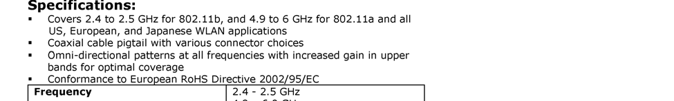


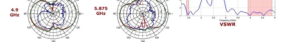
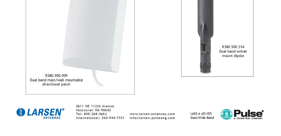
21 Appendix D Antenna Specification Sheet File: R71976 Rev. 1 Page 21 of 25


22 File: R71976 Rev. 1 Page 22 of 25

23 File: R71976 Rev. 1 Page 23 of 25
24 File: R71976 Rev. 1 Page 24 of 25


25 Appendix E Test Configuration Photographs File: R71976 Rev. 1 Page 25 of 25
TCB Workshop. Unlicensed National Information Infrastructure Devices (U-NII)/Dynamic Frequency Selection (DFS)
/Dynamic Frequency Selection (DFS)") 1 TCB Workshop Unlicensed National Information Infrastructure Devices (U-NII)/Dynamic Frequency Selection (DFS) Andrew Leimer Office of Engineering and Technology/Equipment Authorization Branch FCC Laboratory
1 TCB Workshop Unlicensed National Information Infrastructure Devices (U-NII)/Dynamic Frequency Selection (DFS) Andrew Leimer Office of Engineering and Technology/Equipment Authorization Branch FCC Laboratory
Dynamic Frequency Selection (DFS) and the 5GHz Unlicensed Band
 and the 5GHz Unlicensed Band") Dynamic Frequency Selection (DFS) and the 5GHz Unlicensed Band by Mark Briggs, Principal Engineer, Elliott Laboratories- An NTS Company Note: This article combines the content from several papers released
Dynamic Frequency Selection (DFS) and the 5GHz Unlicensed Band by Mark Briggs, Principal Engineer, Elliott Laboratories- An NTS Company Note: This article combines the content from several papers released
Dynamic Frequency Selection Requirements
 Elliott Laboratories Presents Dynamic Frequency Selection Requirements An overview of radar detection requirements for wireless devices operating in the 5 GHz band (with emphasis on the new FCC rules)
AN1200.04. Application Note: FCC Regulations for ISM Band Devices: 902-928 MHz. FCC Regulations for ISM Band Devices: 902-928 MHz
 AN1200.04 Application Note: FCC Regulations for ISM Band Devices: Copyright Semtech 2006 1 of 15 www.semtech.com 1 Table of Contents 1 Table of Contents...2 1.1 Index of Figures...2 1.2 Index of Tables...2
Measurement of RF Emissions from a Final Coat Electronics Corrosion Module
 Engineering Test Report No. 37802-02 Rev. A Measurement of RF Emissions from a Final Coat Electronics Corrosion Module For : Canadian Auto Preservation, Inc. 390 Bradwick Drive Concord, Ontario CANADA
EN 301 489-17 v1.2.1 TEST REPORT FOR. 802.11ag/Draft 802.11n WLAN PCI-E Mini Card MODEL NUMBER: BCM94322MC REPORT NUMBER: 07U11529-5
 EN 301 489-17 v1.2.1 TEST REPORT FOR 802.11ag/Draft 802.11n WLAN PCI-E Mini Card MODEL NUMBER: BCM94322MC REPORT NUMBER: 07U11529-5 ISSUE DATE: JANUARY 29, 2008 Prepared for BROADCOM CORPORATION 190 MATHILDA
Radio Frequency Exposure Test Report
 Radio Frequency Exposure EN 62311 January 2008 Assessment of electronic and electrical equipment related to human exposure restrictions for electromagnetic fields (0Hz 300GHz) (IEC 62311:2007, modified)
TEST REPORT FROM RFI GLOBAL SERVICES LTD
 FROM RFI GLOBAL SERVICES LTD Partial Test of: BTM411 To: EN 300 328 V1.7.1 (2006-10) Test Report Serial No: RFI/RPT1/RP76018JD01A This Test Report Is Issued Under The Authority Of Brian Watson, Operations
Application Note AN-00126
 Considerations for Operation within the 902-928MHz Band Application Note AN-00126 Introduction This application note is designed to give the reader a basic understanding of the legal and technical considerations
Report Of. Shielding Effectiveness Test For. SafeSleeve Radiation Shielding Technology. Test Date(s): June 07 June 09, 2015
: June 07 June 09, 2015") Report Of Shielding Effectiveness Test For SafeSleeve Radiation Shielding Technology Test Date(s): June 07 June 09, 2015 Issue Date: June 10, 2015 UST Project No: 15-0137 Total Number of Pages Contained
Report Of Shielding Effectiveness Test For SafeSleeve Radiation Shielding Technology Test Date(s): June 07 June 09, 2015 Issue Date: June 10, 2015 UST Project No: 15-0137 Total Number of Pages Contained
ETSI EN 300 328-1 V1.2.2 (2000-07)
") EN 300 328-1 V1.2.2 (2000-07) European Standard (Telecommunications series) Electromagnetic compatibility and Radio spectrum Matters (ERM); Wideband Transmission systems; data transmission equipment operating
EN 300 328-1 V1.2.2 (2000-07) European Standard (Telecommunications series) Electromagnetic compatibility and Radio spectrum Matters (ERM); Wideband Transmission systems; data transmission equipment operating
MYRICOM, INC. TEST REPORT FOR THE SERVER RACK, 10G-PCIE2-8B2-2S & 10G-PCIE2-8B2-2QP FCC PART 15 SUBPART B SECTIONS 15.107 AND 15.109 CLASS A TESTING
 TESTING CERT #803.01, 803.02, 803.05, 803.06 MYRICOM, INC. TEST REPORT FOR THE SERVER RACK, 10G-PCIE2-8B2-2S & 10G-PCIE2-8B2-2QP FCC PART 15 SUBPART B SECTIONS 15.107 AND 15.109 CLASS A TESTING DATE OF
Electromagnetic Compatibility Test Report Test results of Floww equipment
 Electromagnetic Compatibility Test Report Test results of Floww equipment Reference number Status test report Brand Model number : 10C00357RPT01.doc : Final : Floww : mobilefloww screenfloww pocketfloww
RADIO TEST REPORT. EN 300 440-2 SRD radio equipment to be used in the 1 GHz to 40 GHz frequency range. DAkkS - Registration number : D-PL-12092-01-01
 RADIO TEST REPORT SRD radio equipment to be used in the 1 GHz to 40 GHz frequency range Report Reference No.... : G0M-1206-2043-TEU440G-V01 Testing Laboratory... : Eurofins Product Service GmbH Address...
AN437. Si4432 RF PERFORMANCE AND FCC COMPLIANCE TEST RESULTS. 1. Introduction. 2. Relevant Measurements to comply with FCC
 Si4432 RF PERFORMANCE AND FCC COMPLIANCE TEST RESULTS 1. Introduction This document provides measurement results and FCC compliance results for the Si4432B when operated from 902 928 MHz. The measurement
FCC PART 15B CLASS A MEASUREMENT AND TEST REPORT
 FCC PART 15B CLASS A MEASUREMENT AND TEST REPORT For SAMBO HI TECH CO., LTD. 616-15, GANSUK4-DONG, NAMDONG-GU, INCHUN 405-810, KOREA Model: LSR700, SCI545HV1EF, SCI545HVEF This Report Concerns: Original
ETSI EN 302 774 V1.2.1 (2012-02)
") EN 302 774 V1.2.1 (2012-02) Harmonized European Standard Broadband Wireless Access Systems (BWA) in the 3 400 MHz to 3 800 MHz frequency band; Base Stations; Harmonized EN covering the essential requirements
EN 302 774 V1.2.1 (2012-02) Harmonized European Standard Broadband Wireless Access Systems (BWA) in the 3 400 MHz to 3 800 MHz frequency band; Base Stations; Harmonized EN covering the essential requirements
ACRS 2.0 User Manual 1
 ACRS 2.0 User Manual 1 FCC Regulatory Information This device complies with part 15 of the FCC Rules. Operation is subject to the following two conditions: (1) This device may not cause harmful interference,
Application Note AN-00125
 Considerations for Operation within the 260 470MHz Band Introduction This application note is designed to give the reader a basic understanding of the legal and technical considerations for operation of
Test Report #: 1981-3 Date: April 8, 2005
 Test Report #: 1981-3 Date: April 8, 2005 CERTIFICATE #2316.01 Issued To: Bill Burks American Power Conversion 85 Rangeway Road North Billerica, MA 01862 USA 978-670-2440 Product Name/Description Model
Federal Communications Commission Office of Engineering and Technology Laboratory Division
 Federal Communications Commission Office of Engineering and Technology Laboratory Division August 14, 2014 GUIDANCE ON SOFTWARE OR NETWORK CONFIGURATION OF NON-SDR DEVICES TO ENSURE COMPLIANCE I. GENERAL
Regulatory requirements - USA
 Regulatory requirements - USA FCC CFR 47 Part 2 & 15 Radiospectrum and EMF Test on qualified laboratory Test methods different from EU Certification required TCB or FCC Grant Regulatory EMC requirements
CE Test Report. : Microchip Technology Inc. 2355 West Chandler Blvd., Chandler, Arizona 85224-6199, USA
 CE Test Report Equipment : IEEE 802.11b/g Wireless LAN module Brand Name : MICROCHIP Model No. : MRF24WG0MA/MB Standard : EN 300 328 V1.8.1 (2012-06) Operating Band : 2400 MHz 2483.5 MHz Applicant Manufacturer
FCC PART 15 SUBPART C EMI MEASUREMENT AND TEST REPORT
 FCC PART 15 SUBPART C EMI MEASUREMENT AND TEST REPORT For AeroComm, Inc. 10981 Eicher Drive Lenexa, KS 66219 2003-05-22 This Report Concerns: Original Report Equipment Type: 900MHz Transceiver Test Engineer:
Standard: EN 61000-4-2 :1995, EN 61000-4-3 :1996, ENV 50204 :1993, & EN 61000-4-4 :1995 Solid State Energy Meter
 Standard: EN 61000-4-2 :1995, EN 61000-4-3 :1996, ENV 50204 :1993, & EN 61000-4-4 :1995 Model: Solid State Energy Meter Prepared for: Analog Devices, Inc. 804 Woburn Street Wilmington, MA 01887 Date of
Wharf T&T Limited Report of Wireless LAN Technology Trial Version: 1.0 Date: 26 Jan 2004. Wharf T&T Limited. Version: 1.0 Date: 26 January 2004
 Wharf T&T Limited Version: 1.0 Date: 26 January 2004 This document is the property of Wharf T&T Limited who owns the copyright therein. Without the written consent of Wharf T&T Limited given by contract
Fast and Accurate Test of Mobile Phone Boards
 Products: R&S FSP Fast and Accurate Test of Mobile Phone Boards Short test times in conjunction with accurate and repeatable measurement results are essential when testing and calibrating mobile phones
Embedded FM/TV Antenna System
 1 Embedded FM/TV Antenna System Final Report Prepared for By January 21, 2011 2 Table of Contents 1 Introduction... 5 2 Technical Specification... 6 3 Prototype Antenna... 7 4 FASTROAD Active module fabrication...
RECOMMENDATION ITU-R SM.1792. Measuring sideband emissions of T-DAB and DVB-T transmitters for monitoring purposes
 Rec. ITU-R SM.1792 1 RECOMMENDATION ITU-R SM.1792 Measuring sideband emissions of T-DAB and DVB-T transmitters for monitoring purposes (2007) Scope This Recommendation provides guidance to measurement
Optical Fibres. Introduction. Safety precautions. For your safety. For the safety of the apparatus
 Please do not remove this manual from from the lab. It is available at www.cm.ph.bham.ac.uk/y2lab Optics Introduction Optical fibres are widely used for transmitting data at high speeds. In this experiment,
CX380X Advanced Spectrum and Burst QAM Analyzer
 Advanced Spectrum and Burst QAM Analyzer Preventative Network Monitoring With VeEX s VeSion system, the s advanced Spectrum Analyzer and Bursty Demodulator captures rogue cable modems and provides proactive
Test result: SHENZHEN TIMEWAY TECHNOLOGY CONSULTING CO LTD. ISO/IEC17025Accredited Lab. Report No: FCC 1106180 File reference No: 2011-07-18
 Report No: FCC 1106180 File reference No: 2011-07-18 ISO/IEC17025Accredited Lab. Applicant: FUJIAN NAN AN BAOFENG ELECTRONICS CO., LTD Product: Model No: Trademark: Two Way Radio UV-3R BAOFENG Test Standards:
TEST REPORT EN 55014-2 (1997) +A1 (2001)
 +A1 (2001)") Page 1 of 23 TEST REPORT EN 55014-2 (1997) +A1 (2001) Electromagnetic compatibility - Requirements for household appliances, electric tools and similar apparatus Part 2: Immunity Report Reference No....
Page 1 of 23 TEST REPORT EN 55014-2 (1997) +A1 (2001) Electromagnetic compatibility - Requirements for household appliances, electric tools and similar apparatus Part 2: Immunity Report Reference No....
PXI. www.aeroflex.com. GSM/EDGE Measurement Suite
 PXI GSM/EDGE Measurement Suite The GSM/EDGE measurement suite is a collection of software tools for use with Aeroflex PXI 3000 Series RF modular instruments for characterising the performance of GSM/HSCSD/GPRS
Impedance 50 (75 connectors via adapters)
") VECTOR NETWORK ANALYZER PLANAR TR1300/1 DATA SHEET Frequency range: 300 khz to 1.3 GHz Measured parameters: S11, S21 Dynamic range of transmission measurement magnitude: 130 db Measurement time per point:
VECTOR NETWORK ANALYZER PLANAR TR1300/1 DATA SHEET Frequency range: 300 khz to 1.3 GHz Measured parameters: S11, S21 Dynamic range of transmission measurement magnitude: 130 db Measurement time per point:
Design Considerations for DVT and Manufacturing Test of Wireless Devices
 WHITEPAPER Design Considerations for DVT and Manufacturing Test of Wireless Devices 2015 LitePoint, A Teradyne Company. All rights reserved. Introduction Wireless devices are being deployed for a wide
EE 186 LAB 2 FALL 2004. Network Analyzer Fundamentals and Two Tone Linearity
 Network Analyzer Fundamentals and Two Tone Linearity Name: Name: Name: Objective: To become familiar with the basic operation of a network analyzer To use the network analyzer to characterize the in-band
Test Report. Prepared for: Technologic Systems, Inc. Model: TS-8820
 Test Report Prepared for: Technologic Systems, Inc. Model: TS-8820 Description: Single Board Computer with Analog and Digital Inputs and Outputs, Relays, and RS-232/485 Ports To IEC 61000-6-1 (2005-03)
Spectrum and Power Measurements Using the E6474A Wireless Network Optimization Platform
 Application Note Spectrum and Power Measurements Using the E6474A Wireless Network Optimization Platform By: Richard Komar Introduction With the rapid development of wireless technologies, it has become
FCC RF Exposure Report
 FCC RF Exposure Report FCC ID Equipment Model No. Brand Name Applicant : SQGBT800 : BTv4.0 Dual Mode USB Dongle : BT820 : Laird Technologies : Laird Technologies Address : 11160 Thompson Ave. / Lenexa,
Monitores Equipos Móviles Especificaciones de Producto
 EquipManager -4 F/-20 C to +140 F/+60 C (optional heater available for cold room applications) 0 100% noncondensing User-adjustable threshold 0.3G to 7G 10G (nondestructive)/100g (destructive) Piezoelectric
Agilent U2000 Series USB Power Sensors
 Agilent U2000 Series USB Power Sensors GSM Timeslot Burst Power Measurement Product Note Table of Content Introduction 2 Measuring GSM Timeslot 4 Signal Overview of Agilent U2000 5 Series USB Power Sensors
NI USB-5681 RF Power Meter Specifications
 NI USB-568 RF Power Meter Specifications General This document lists specifications for the NI USB-568 RF power meter. Minimum or maximum specifications are warranted under the following conditions: hour
Small Entity Compliance Guide
 Federal Communications Commission Washington, D.C. 20554 April 18, 2013 DA 13-791 Small Entity Compliance Guide Operation of Unlicensed Personal Communications Service Devices in the 1920-1930 MHz Band
R&S ZNC Vector Network Analyzer Specifications
 ZNC3_dat-sw_en_5214-5610-22_v0300_cover.indd 1 Data Sheet 03.00 Test & Measurement R&S ZNC Vector Network Analyzer Specifications 04.09.2012 13:39:47 CONTENTS Definitions... 3 Measurement range... 4 Measurement
User Guide. Guide d utilisation Guida dell'utente Benutzerhandbuch Guía del usuario Guia do Usuário WNA-100. Wireless Network Adapter
 WNA-100 Wireless Network Adapter User Guide Guide d utilisation Guida dell'utente Benutzerhandbuch Guía del usuario Guia do Usuário www.xerox.com/office/wna Copyright 2007 Xerox Corporation. All Rights
Testing of 10 GHz Instantaneous Bandwidth RF Spectrum Monitoring at Idaho National Labs
 Testing of 10 GHz Instantaneous Bandwidth RF Spectrum Monitoring at Idaho National Labs Scott H. Bekker, Aaron S. Traxinger, Colton R. Stiffler, Alex J. Woidtke, Michael D. Chase, Wm. Randall Babbitt,
Technical Datasheet Scalar Network Analyzer Model 8003-10 MHz to 40 GHz
 Technical Datasheet Scalar Network Analyzer Model 8003-10 MHz to 40 GHz The Giga-tronics Model 8003 Precision Scalar Network Analyzer combines a 90 db wide dynamic range with the accuracy and linearity
Rated Power(W) 8W 2. EG-LED0840-01 8W 3. EG-LED1027-01 10W
 8W 2. EG-LED0840-01 8W 3. EG-LED1027-01 10W") 14713221 001 Seite 2 von 37 Page 2 of 37 Model List: No Model Rated Voltage(V) 1. EG-LED0827-01 Rated Power(W) 8W 2. EG-LED0840-01 8W 3. EG-LED1027-01 10W 4. EG-LED1040-01 AC 100-240V, 10W 5. EG-LED1027-02
14713221 001 Seite 2 von 37 Page 2 of 37 Model List: No Model Rated Voltage(V) 1. EG-LED0827-01 Rated Power(W) 8W 2. EG-LED0840-01 8W 3. EG-LED1027-01 10W 4. EG-LED1040-01 AC 100-240V, 10W 5. EG-LED1027-02
Tri-Band RF Transceivers for Dynamic Spectrum Access. By Nishant Kumar and Yu-Dong Yao
 Tri-Band RF Transceivers for Dynamic Spectrum Access By Nishant Kumar and Yu-Dong Yao Presentation outline Introduction to WISELAB Active work at WISELAB Tri-band test bed Elements of the test bed Experimentation
RFSPACE CLOUD-IQ #CONNECTED SOFTWARE DEFINED RADIO
 CLOUD-IQ #CONNECTED SOFTWARE DEFINED RADIO 1 - SPECIFICATIONS Cloud-IQ INTRODUCTION The Cloud-IQ is a high performance, direct sampling software radio with an ethernet interface. It offers outstanding
R&S ZNBT8 Vector Network Analyzer Specifications
 ZNBT8_dat-sw_en_3606-9727-22_v0200_cover.indd 1 Data Sheet 02.00 Test & Measurement R&S ZNBT8 Vector Network Analyzer Specifications 20.05.2014 08:39:42 CONTENTS Definitions... 3 Measurement range... 4
Analysis of Immunity by RF Wireless Communication Signals
 64 PIERS Proceedings, Guangzhou, China, August 25 28, 2014 Analysis of Immunity by RF Wireless Communication Signals Hongsik Keum 1, Jungyu Yang 2, and Heung-Gyoon Ryu 3 1 EletroMagneticwave Technology
Experiment 7: Familiarization with the Network Analyzer
 Experiment 7: Familiarization with the Network Analyzer Measurements to characterize networks at high frequencies (RF and microwave frequencies) are usually done in terms of scattering parameters (S parameters).
A Guide to Calibrating Your Spectrum Analyzer
 A Guide to Calibrating Your Application Note Introduction As a technician or engineer who works with electronics, you rely on your spectrum analyzer to verify that the devices you design, manufacture,
USB 3.0* Radio Frequency Interference Impact on 2.4 GHz Wireless Devices
 USB 3.0* Radio Frequency Interference Impact on 2.4 GHz Wireless Devices White Paper April 2012 Document: 327216-001 INFORMATION IN THIS DOCUMENT IS PROVIDED IN CONNECTION WITH INTEL PRODUCTS. NO LICENSE,
Tuning a Monopole Antenna Using a Network Analyzer
 11/21/11 Tuning a Monopole Antenna Using a Network Analyzer Chris Leonard Executive Summary: When designing a monopole antenna it is important to know at which frequency the antenna will be operating at.
Department of Electrical and Computer Engineering Ben-Gurion University of the Negev. LAB 1 - Introduction to USRP
 Department of Electrical and Computer Engineering Ben-Gurion University of the Negev LAB 1 - Introduction to USRP - 1-1 Introduction In this lab you will use software reconfigurable RF hardware from National
Remarkable achievements
 Remarkable achievements 149.2 km link over water providing 8E1 throughput with 99,99% annual availability Radio link transmitting data from 25km height in Stratosphere to 149km ground station Largest MW
Group of Administrative Co-operation Under the R&TTE Directive. 5 th R&TTE Market Surveillance Campaign on WLAN 5 GHz
 Group of Administrative Co-operation Under the R&TTE Directive 5 th R&TTE Market Surveillance Campaign on WLAN 5 GHz REPORT ON THE 5 TH JOINT CROSS-BORDER R&TTE MARKET SURVEILLANCE CAMPAIGN (2013) WLAN
Radio Frequency (RF) Exposure Compliance of Radiocommunication Apparatus (All Frequency Bands)
 Exposure Compliance of Radiocommunication Apparatus (All Frequency Bands)") Issue 3 June 2009 Spectrum Management and Telecommunications Radio Standards Specification Radio Frequency (RF) Exposure Compliance of Radiocommunication Apparatus (All Frequency Bands) Aussi disponible
Issue 3 June 2009 Spectrum Management and Telecommunications Radio Standards Specification Radio Frequency (RF) Exposure Compliance of Radiocommunication Apparatus (All Frequency Bands) Aussi disponible
Application Note: Spread Spectrum Oscillators Reduce EMI for High Speed Digital Systems
 Application Note: Spread Spectrum Oscillators Reduce EMI for High Speed Digital Systems Introduction to Electro-magnetic Interference Design engineers seek to minimize harmful interference between components,
RF Measurements Using a Modular Digitizer
 RF Measurements Using a Modular Digitizer Modern modular digitizers, like the Spectrum M4i series PCIe digitizers, offer greater bandwidth and higher resolution at any given bandwidth than ever before.
A DESCRIPTION OF THE SOFTWARE ELEMENT OF THE NASA EME FLIGHT TESTS
 NASA Contractor Report 201635 A DESCRIPTION OF THE SOFTWARE ELEMENT OF THE NASA EME FLIGHT TESTS Sandra V. Koppen Lockheed Martin Engineering & Sciences Company, Hampton, Virginia 23666 Contract: NAS1-19000
How To Sell A Talan
 The TALAN represents state-of-the-art capability to rapidly and reliably detect and locate illicit tampering and security vulnerabilities on both digital and analog telephone systems. Marketing Characteristics
Model Rules for License-Exempt White Space Devices
 Model Rules for License-Exempt White Space Devices 1 Permissible Frequencies of Operation. (a) White space devices ( WSDs ) are permitted to operate on a license-exempt basis subject to the interference
AN003. Evaluation of Anechoic Chambers For EMC Measurements Using A CNE. Overview. CNE III 9kHz to 2GHz Conducted and radiated output
 Evaluation of Anechoic Chambers For EMC Measurements Using A CNE Overview Anechoic chambers are used for EMC testing primarily for radiated emissions (RE) and radiated immunity (RI) in the frequency range
Ultra Wideband Signal Impact on IEEE802.11b Network Performance
 Ultra Wideband Signal Impact on IEEE802.11b Network Performance Matti Hämäläinen 1, Jani Saloranta 1, Juha-Pekka Mäkelä 1, Tero Patana 2, Ian Oppermann 1 1 Centre for Wireless Communications (CWC), University
GSM/EDGE Output RF Spectrum on the V93000 Joe Kelly and Max Seminario, Verigy
 GSM/EDGE Output RF Spectrum on the V93000 Joe Kelly and Max Seminario, Verigy Introduction A key transmitter measurement for GSM and EDGE is the Output RF Spectrum, or ORFS. The basis of this measurement
SR2000 FREQUENCY MONITOR
 SR2000 FREQUENCY MONITOR THE FFT SEARCH FUNCTION IN DETAILS FFT Search is a signal search using FFT (Fast Fourier Transform) technology. The FFT search function first appeared with the SR2000 Frequency
Troubleshooting Problems Affecting Radio Frequency Communication
 Troubleshooting Problems Affecting Radio Frequency Communication Document ID: 8630 Refer to the Cisco Wireless Downloads (registered customers only) page in order to get Cisco Aironet drivers, firmware
User manual BETSO WTCS. 16 channel wireless digital TC slate. 1 Copyright BETSO ELECTRONICS Ltd.
 16 channel wireless digital TC slate 1 Copyright BETSO ELECTRONICS Ltd. Contents 1. Product description...3 2. Top features...3 3. Control elements...4 4. Insertion of batteries / accumulators...6 5. External
Field Calibration Software
 SIGNAL HOUND Field Calibration Software User s Manual Version 1.1.0 7/8/2016 This information is being released into the public domain in accordance with the Export Administration Regulations 15 CFR 734
FCC Test Report. FCC Part 22, 24 / RSS 132, 133 FOR: GSM Cellular Telephone with Bluetooth and WiFi. Model #: A1203
 FCC Test Report FCC Part 22, 24 / RSS 132, 133 FOR: GSM Cellular Telephone with Bluetooth and WiFi Model #: A1203 Apple Inc. 1 Infinite Loop Mail Stop26A Cupertino, California 95014 U.S.A FCC ID: BCGA1203
MEASUREMENT AND ANALYSIS OF RF EME LEVELS FROM MOBILE TELEPHONE BASE STATIONS LOCATED AT LEICHHARDT, NSW
 AUSTRALIAN RADIATION PROTECTION AND NUCLEAR SAFETY AGENCY A R P N S A Lower Plenty Road YALLAMBIE VIC 3085 Phone 61 3 9433 2211 Fax 61 3 9432 1835 E-mail: arpansa@health.gov.au Web: www.arpansa.gov.au
Raptor RXi Ultra-fast scanning Countersurveillance Receiver
 data sheet RAPTOR RXi DATA SHEET A MATTER A MATTER OF OF NATIONAL SECURITY Raptor RXi Ultra-fast scanning Countersurveillance Receiver Features + Scans 26GHz in less than 4 seconds at 3kHz resolution (approx.
Spectrum Analyzer Two models available: OGR-24 (24 GHz) and OGR-8 (8 GHz)
 and OGR-8 (8 GHz)") Whip antenna extension connector Auto Switching (utilizes 5 independent antennas) Green ADVANTAGES OSCOR FAST SWEEP TIME Headphone Jack 24 GHz IN LESS THAN 1 SECOND (depending on model) COMPLETE PACKAGE
Whip antenna extension connector Auto Switching (utilizes 5 independent antennas) Green ADVANTAGES OSCOR FAST SWEEP TIME Headphone Jack 24 GHz IN LESS THAN 1 SECOND (depending on model) COMPLETE PACKAGE
Antenna Measurements with the Network Analyzer. Presented by Ernie Jackson RF/uW Applications Engineer Agilent Technologies
 Antenna Measurements with the Network Analyzer Presented by Ernie Jackson RF/uW Applications Engineer Agilent Technologies Purpose During this presentation you will: Learn about interface requirements
SPECIAL SPECIFICATION 6819 Wireless Ethernet Microwave Radio
 2004 Specifications CSJ 2266-02-127 SPECIAL SPECIFICATION 6819 Wireless Ethernet Microwave Radio 1. Description. Furnish and install Wireless Ethernet Microwave Radio (WEMR) as shown on the plans, as detailed
AM/FM/ϕM Measurement Demodulator FS-K7
 Data sheet Version 02.00 AM/FM/ϕM Measurement Demodulator FS-K7 July 2005 for the Analyzers FSQ/FSU/FSP and the Test Receivers ESCI/ESPI AM/FM/ϕM demodulator for measuring analog modulation parameters
CANOPY TM AP C A N O P Y C A N O P Y. Getting Started with Motorola REV 12/18/01. Specifications
 Specifications Operating Frequency Range U-NII Mid band 5.25 to 5.35 GHz Access Method TDD/TDMA Data Rate 10 Mbps Modulation Type High Index BFSK/4FSK (Optimized for interference rejection) Carrier to
UNDERSTANDING THE FCC REGULATIONS FOR LOW-POWER, NON-LICENSED TRANSMITTERS
 Office of Engineering and Technology Federal Communications Commission UNDERSTANDING THE FCC REGULATIONS FOR LOW-POWER, NON-LICENSED TRANSMITTERS OET BULLETIN NO. 63 October 1993 (Supersedes September
Antenna Deployment Technical Brief
 ProCurve Networking Antenna Deployment Technical Brief Introduction... 2 Antenna types... 2 Omni directional antennas... 2 Directional antennas... 2 Diversity antennas... 3 High gain directional antennas...
ECC/DEC/(04)08 ELECTRONIC COMMUNICATIONS COMMITTEE
08 ELECTRONIC COMMUNICATIONS COMMITTEE") ELECTRONIC COMMUNICATIONS COMMITTEE ECC Decision of 09 July 2004 on the harmonised use of the 5 GHz frequency bands for the implementation of Wireless Access Systems including Radio Local Area Networks
ELECTRONIC COMMUNICATIONS COMMITTEE ECC Decision of 09 July 2004 on the harmonised use of the 5 GHz frequency bands for the implementation of Wireless Access Systems including Radio Local Area Networks
ETSI EN 300 328 V1.7.1 (2006-10)
") EN 300 328 V1.7.1 (2006-10) Harmonized European Standard (Telecommunications series) Electromagnetic compatibility and Radio spectrum Matters (ERM); Wideband transmission systems; Data transmission equipment
EN 300 328 V1.7.1 (2006-10) Harmonized European Standard (Telecommunications series) Electromagnetic compatibility and Radio spectrum Matters (ERM); Wideband transmission systems; Data transmission equipment
Experiment 5. Lasers and laser mode structure
 Northeastern University, PHYS5318 Spring 2014, 1 1. Introduction Experiment 5. Lasers and laser mode structure The laser is a very important optical tool that has found widespread use in science and industry,
LTE in Unlicensed Spectrum: European Regulation and Co-existence Considerations
 3GPP workshop on LTE in unlicensed spectrum Sophia Antipolis, France, June 13, 2014 RWS-140002 LTE in Unlicensed Spectrum: European Regulation and Co-existence Considerations Sari Nielsen & Antti Toskala
ETSI EN 300 328-2 V1.1.1 (2000-07)
") EN 300 328-2 V1.1.1 (2000-07) Candidate Harmonized European Standard (Telecommunications series) Electromagnetic compatibility and Radio spectrum Matters (ERM); Wideband Transmission systems; data transmission
EN 300 328-2 V1.1.1 (2000-07) Candidate Harmonized European Standard (Telecommunications series) Electromagnetic compatibility and Radio spectrum Matters (ERM); Wideband Transmission systems; data transmission
Long-Range 500mW IEEE 802.11g Wireless USB Adapter. User's Guide
 Long-Range 500mW IEEE 802.11g Wireless USB Adapter User's Guide TABLE OF CONTENTS OVERVIEW... 4 UNPACKING INFORMATION... 4 INTRODUCTION TO THE IEEE 802.11G WIRELESS USB ADAPTER... 5 Key Features...5 INSTALLATION
PHOENIX CONTACT - 03/2007
 PSI-WL-PLUG-USB/ Bluetooth USB Adapter INTERFACE Data Sheet 103170_00_en PHOENIX CONTACT - 03/2007 Description The Bluetooth USB adapter provides an easy wireless connection between devices with a USB
Conducting a WLAN Site Survey and Implementation for the Cisco Unified Wireless Network
 Conducting a WLAN Site Survey and Implementation for the Cisco Unified Wireless Network Author: Keven Dech, Director of Training Services, CCSI, CCDA All content is the property of GigaWave Technologies
DCM555 - Data Communications Lab 8 Time Division Multiplexing (TDM) Part 1 - T1/DS1 Signals
 Part 1 - T1/DS1 Signals") DCM555 - Data Communications Lab 8 Time Division Multiplexing (TDM) Part 1 - T1/DS1 Signals Name: St. #: Section: (Note: Show all of your calculations, express your answer to the appropriate number of
DCM555 - Data Communications Lab 8 Time Division Multiplexing (TDM) Part 1 - T1/DS1 Signals Name: St. #: Section: (Note: Show all of your calculations, express your answer to the appropriate number of
CE Test Report. : BL600 Series Bluetooth Low Energy Module
 CE Test Report Equipment Brand Name Model No. : BL600 Series Bluetooth Low Energy Module : Laird Technologies : BL600-SA, BL600-SC, BL600-ST Additional Model No. : BL620-SA, BL620-SC, BL620-ST Standard
Cisco Aironet Wireless Bridges FAQ
 Cisco Aironet Wireless Bridges FAQ Document ID: 16041 Contents Introduction What is the Cisco Aironet Wireless Bridge? What are the different platforms of wireless bridges that Cisco offers? Where can
Uncertainty evaluations in EMC measurements
 Uncertainty evaluations in EMC measurements Carlo Carobbi Dipartimento di Elettronica e Telecomunicazioni Università degli Studi di Firenze Politecnico di Milano - 20 Feb. 2009 1 Non - reproducibility
Application Note Noise Frequently Asked Questions
 : What is? is a random signal inherent in all physical components. It directly limits the detection and processing of all information. The common form of noise is white Gaussian due to the many random
PRO 5000 CPE 1D Quick Installation Guide
 PRO 5000 CPE 1D Quick Installation Guide Introduction This Quick Installation Guide covers the basic installation of the PRO 5000 CPE. For more information, refer to the relevant sections in the Product
Module 13 : Measurements on Fiber Optic Systems
 Module 13 : Measurements on Fiber Optic Systems Lecture : Measurements on Fiber Optic Systems Objectives In this lecture you will learn the following Measurements on Fiber Optic Systems Attenuation (Loss)
Deliberant.com, 2011. Technology review
 Technology review 11N advantages Parameter 802.11a/g 802.11n 2x2 Improvement factor Data rate, Mbps 108 300 2.7x Max throughput, h t Mbps 45 150 3.3x3 Spectral efficiency, bit/hz 1.125 3.75 3.3x Signal
What is 802.11? Why are standards important?
 What is 802.11? The 802.11 standards are a group of evolving specifications defined by the Institute of Electrical and Electronic Engineers (IEEE). Commonly referred to as Wi Fi the 802.11 standards define