INSTRUCTABLES PRANK BOX JAMECO PART NO
|
|
|
- Samson Washington
- 7 years ago
- Views:
Transcription
1 INSTRUCTABLES PRANK BOX JAMECO PART NO The Prank Box is basically a sealed wooden box with an electric bell inside that is activated by a key switch. Once it is turned on, a relay inside the box is latched and it cannot be turned off without knowing the secret trick (spoiler alert: magnets). Quite understandably, a completely sealed box with a ringing bell inside that doesn't seem to stop can quickly become maddening. It is very funny to watch people ponder the implications of the device, reluctantly turn it on, and then stress out when they cannot turn it off. It is even funnier to get panicked s from your friend in Canada after you mail it to him without any explanation, and he decides to ignore the directions on the box and turn it on. Experience Level: Beginner Time Required: 5-8 hours Required tools and parts: Wood glue & woodworking tools Heat gun Paintbrushes Epoxy Electric bell Drill and 1/8 drill bit Red and black wire Clamps Soldering iron Bill of Materials: Jameco Quantity SKU Component Name Magnetic Proximity Reed Switch Round Keylock Switch Metal 9V Battery Holder V Battery Snap D Battery Holder PC Mount Relay Heat Shrink Tubing V Alkaline Battery D-Cell Alkaline Battery Cable Ties


2 Step 1 Review Parts and Download Templates Take a moment to be sure you have all the required parts. You can download the two template files titled "DoNotBox.cdr" and "DoNotBox.eps" here: Step 2 Insert Lock Insert the lock into the hole in the front panel from front to back and then epoxy it firmly in place. Step 3: Mark Mounting Holes for Components Place the wooden mounting bracket atop the bottom side of the box and place all of the components atop their designated spots on the bracket. The reed switch does not have a designated spot, but it should line up flush with the edge of the bracket on the side nearest the 9V battery holder.


3 Step 4: Glue the Inner-Side of the Box Bottom The bracket should be placed on top and line up to the edge of the box, so when the box is put together the reed switch is flush against the wall of the box. Clamp in place and wait for it to dry.


4 Step 5: Drill Mounting Holes Drill the mounting holes with a 1/8" drill bit. It should go deep into the wood, but not pass all the way through. Step 6: Mount Components Lay two zip ties vertically across the battery holder's footprint and another two horizontally and mount all of the major components to the bracket with screws.


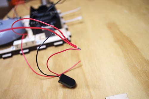
5 Step 7: Wire It Up Attach the red wire to the common connections for the reed switch and the key switch. Then attach another red wire to the normally open (NO) connections on both switches. Connect these two wires to the red wire from the 9V battery clip. Attach black wires to the two normally closed (NC) connections on both switches. Connect these two wires to the black wire from the 9V battery clip. What you have just done is create a situation in which ground is always connected in the circuit. By engaging one of the switches, you are introducing a positive voltage. This flips the polarity one way or another and latches the relay open or closed. Now when you turn the key, it latches it closed and keeps the bell ringing. When you engage the reed switch, it flips the polarity and latches it open and turns off the bell. You will need to wire the bell to the D battery holder and the relay. First, wire together the black wire from the battery holder to the frame of the bell. Then connect the red wire from the battery holder to the center pin on the


6 relay. Last, connect the red wire from the battery holder to the coil connection on the bell. This is the mounting terminal not connected to the frame. Cover all the exposed electrical connections with shrink tubing.


7


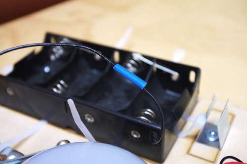
8 Step 8: Heat Shrink Electrical Connections Step 9: Insert Batteries Insert D batteries in the battery holder and using four more zip ties, firmly band all of the batteries in place both vertically and horizontally.


9 Step 10: Glue Relay Plug in the 9V battery and epoxy the battery holder in place. Hot glue the relay to the mounting bracket in the free space next to the battery. Step 11: Bundle Everything Together with Zip Ties If possible, zip tie this bundle to the battery pack to prevent it from interfering with the bell.


10 Step 12: Glue it together Test to make sure the bell turns on and off. Seal the box shut and apply wood glue to all of the joints and firmly clamp it together.


11 Step 13: Use a Belt Sander to Round the Edges Step 14: Make a Sign Laser cut the sign using the template from Step 2. If you don't have a laser cutter, you can use a service like Ponoko, or do this the old-fashioned way with saws, stencils and Exacto blades. Step 15: Sand and Stain (Optional) Sand the box and wipe it clean. You can put on a coat of stain in a singular direction. When it has dried, lightly sand again and apply the stain in the opposite direction. Lightly sand once more and lay one last coat of stain in the initial direction.


12 Step 16: Affix the Sign Step 17: Project Complete It is simply good to distance yourself from the person who engages the box. Remember to be a good southern neighbor and eventually tell them how to turn it off. However, I think minutes is about a fair amount of time to wait before telling them about the magnet triggered reed switch on the side of the box. Also, when triggering the reed switch, make sure the key is not inserted in the lock and turned. If it is, this will not work.

13
DirectCommand Installation DirectCommand 3-Channel Spreader Kit
 Note: Indented items indicate parts included in an assembly listed above Part Name/Description Part Number With Switch Box Quantity With Remote Switch Display Cable Kit 4100814 1 1 Power Control Relay
Permanent Magnet Motor Kit, Magnetic Reed Type. (SKY-ReedMotorKit) Instructions
 Instructions") Permanent Magnet Motor Kit, Magnetic Reed Type (SKY-ReedMotorKit) Instructions This kit contains powerful permanent magnets. Exercise caution when handling them as they can pull on iron tools and snap
Permanent Magnet Motor Kit, Magnetic Reed Type (SKY-ReedMotorKit) Instructions This kit contains powerful permanent magnets. Exercise caution when handling them as they can pull on iron tools and snap
How to Build a Poker Table
 How to Build a Poker Table www.pokertablematerials.com 10-Person Poker Table- 96 x 48 These are step by step instructions for building a poker table. The table will measure 48" x 96" and have a 4" wide
Overnight Sensations Speaker Kit
 Overnight Sensations Speaker Kit Thank you for purchasing the Overnight Sensation cabinet kit. This speaker kit was precision cut using CNC machinery for the best possible fit and finish. With a little
Shunt lock function 3066
 Version: January 2004 Contents Alarm System Activation unit Deactivation unit Digital locking cylinder or Smart Relay 1.0 Method of Operation 4 1.1 General 4 1.2 Turning the Alarm System On 4 1.3 Turning
WIRELESS STATUS MONITOR
 INSTALLATION INSTRUCTIONS WIRELESS STATUS MONITOR (WSM or AUWSM) The most current version of this document is available for download at: http://www.ir-swa.com P/N: M053-032-D Schlage 245 W. Roosevelt Road,
Electronics and Soldering Notes
 Electronics and Soldering Notes The Tools You ll Need While there are literally one hundred tools for soldering, testing, and fixing electronic circuits, you only need a few to make robot. These tools
www.cornholesupplies.com
 www.cornholesupplies.com How To Build Regulation Cornhole Boards Home of the Original Cornhole Bags and Boards Supply List: 1-4' X 8' Piece of Plywood (pre sanded) 4-2" X 4" X 8' Studs (2 by 4s make sure
Hand Crank Generator (9 May 05) Converting a Portable Cordless Drill to a Hand Crank DC Generator
 Converting a Portable Cordless Drill to a Hand Crank DC Generator") Converting a Portable Cordless Drill to a Hand Crank DC Generator The unit is light weight (2.5 lb), portable, low cost ($10-$20) and can be used to recharge single cell batteries at from 1-3.5 amps. It
Converting a Portable Cordless Drill to a Hand Crank DC Generator The unit is light weight (2.5 lb), portable, low cost ($10-$20) and can be used to recharge single cell batteries at from 1-3.5 amps. It
Wine Rack & Glass Storage Bench Chris Gardner
 Wine Rack & Glass Storage Bench Chris Gardner Quantity Length Width Material Part 2 48 16 3/4 birch plywood top, bottom 2 14 16 3/4 birch plywood sides 2 14 13 3/4 birch plywood support dividers 2 3 15
Build a Junior Solar Sprint Model Car Kit Materials: 1 PITSCO Ray Catcher Sprint Kit or Solar Made Junior Solar Sprint Kit 1 White Sheet of Plastic
 Build a Junior Solar Sprint Model Car Kit Materials: 1 PITSCO Ray Catcher Sprint Kit or Solar Made Junior Solar Sprint Kit 1 White Sheet of Plastic Coated Paper 2 Balsa Sheets (10-1/2 x4 x3/16 ) 2 Alligator
1999.5-2001 Audi A4 (B5) HID conversion installation instructions
 HID conversion installation instructions") 1 of 5 10/26/2007 4:48 PM 1999.5-2001 Audi A4 (B5) HID conversion installation instructions Tools Needed: A drill 1" hole saw T27 Torx bit and driver with a 4" extension Extendable magnet Pliers or A drill
1 of 5 10/26/2007 4:48 PM 1999.5-2001 Audi A4 (B5) HID conversion installation instructions Tools Needed: A drill 1" hole saw T27 Torx bit and driver with a 4" extension Extendable magnet Pliers or A drill
2002 2005 Mini Cooper S Grille Install Instructions
 2002 2005 Mini Cooper S Grille Install Instructions Lower Front Grille BEFORE AFTER Package Contents 1 perforated grille (Stiletto, RAZR, or Monster) 6 Zip Tie Mounting Pads 1 is for the temp. sensor 5
COMPLIMENTARY WOODWORKING PLAN
 COMPLIMENTARY WOODWORKING PLAN Adirondack Chair This downloadable plan is copyrighted. Please do not share or redistribute this plan in any way. It has been created for Wilton Tools, a division of WMH
Easy Six Cube Bookshelf. Copyrighted Material. Page 1
 Compare to: Land of Nod Cube Collection, 6 Cube Bookshelf Skill Level: Beginner Easy Six Cube Bookshelf I love the storage cubes in kids rooms because they give you an opportunity to have your children
Stair Parts Installation. Tricks
 Stair Parts Installation Tips & Tricks Introduction Your DIY staircase guide Welcome to the Stairpart home installation guide. Your stairway is both a functional and focal point in your home, so keeping
tidesmarine Smart Seal Temperature Alarm System Generation II Installation Instructions Starboard side cable
 tidesmarine Smart Seal Temperature Alarm System Generation II Installation Instructions Starboard side cable Port side cable (with black cable tie attached) Power cable Preparing for Installation 1 Overall
Bill of Materials: Line Follower: A Zippy Robot That Senses Where to Go PART NO. 2170783
 Line Follower: A Zippy Robot That Senses Where to Go PART NO. 2170783 This kit has the parts you'll need with the exception of a few craft items sold separately to make a line-following cart. It uses a
Triac Printed Circuit Board Replacement
 Technical Service Bulletin: Triac Printed Circuit Board Replacement TRONIC 5000C Pro Models: WH17, WH27, WH36 Introduction Fig. 1 ELECTRICITY IS EXTREMELY DANGEROUS. TAKE EXTRA PRECAUTIONS AND ENSURE ALL
INSTALLATION INSTRUCTIONS
 Rear Vision System Aftermarket and Factory 5.0, 8.4 and 6.1 MyGig Touch Screen Display (Factory Display requires Chrysler/Dodge dealer to activate) 2009 Current* Dodge Ram (Kit part number 1009-6503) *NOTE:
EASY START SYSTEM. Toni Clark practical scale GmbH EASY START SYSTEM 1
 1 GB Toni Clark practical scale GmbH 2 2 INSTALLATION: Unplug the connector in the red lead from power coil to spark coil. Push the round plug of the Easy Start into the power coil s red lead connector.
Replacement Instructions. Warning: During this procedure, keep small parts away from children.
 apple ibook G4 Memory Card Replacement Instructions Follow the instructions in this sheet carefully. Failure to follow these instructions could damage your equipment and void its warranty. Note: Written
Your Simple Guide to Battery. www.firstalertpro.com. Replacement. Customer Care: 1-800-852-0086. www.firstalertpro.
 Previous Menu Your Simple Guide to Battery www.firstalertpro.com Replacement p e t s ts ep -by Customer Care: 1-800-852-0086 FA/1565 9/00 www.firstalertpro.com Table of Contents: page Introduction...............................
EH-20 20m antenna. By VE3RGW
 EH-20 20m antenna By VE3RGW Equivalent circuit of EH-20 (prototype 2A) antenna system. Upper cylinder Lower cylinder Ground Counter pose Phasing coil Impedance transformer and tune circuit Tune coil Feed
RS232/DB9 An RS232 to TTL Level Converter
 RS232/DB9 An RS232 to TTL Level Converter The RS232/DB9 is designed to convert TTL level signals into RS232 level signals. This cable allows you to connect a TTL level device, such as the serial port on
BUILT-IN DISHWASHER INSTALLATION INSTRUCTIONS
 BUILT-IN DISHWASHER INSTALLATION INSTRUCTIONS PLEASE READ COMPLETE INSTRUCTIONS BEFORE YOU BEGIN LEAVE INSTALLATION INSTRUCTIONS AND USER'S GUIDE WITH OWNER ALL ELECTRIC WIRING AND PLUMBING MUST BE DONE
Go-kart for little race-drivers
 Go-kart for little race-drivers Drill and drive. Go-kart What it lacks in speed, it more than makes up for in fun: the go-kart will excite little race-drivers. 1 Introduction It s only a go-kart, but it
ELECTRONIC THERMOSTAT AND THERMOMETER With SPEED CONTROL
 148 OLD CONCORD TURNPIKE, BARRINGTON NH 03825 USA TEL (603) 868-5720 FAX (603) 868-1040 1-800-435-6708 E-Mail:sales@seafrost.com www.seafrost.com ELECTRONIC THERMOSTAT AND THERMOMETER With SPEED CONTROL
C5 Sound Deadening & Insulation Kit Interior Removal & Installation Instructions
 C5 Sound Deadening & Insulation Kit Interior Removal & Installation Instructions Ok, let's start with taking the radio bezel dash area off first. Here is what the OEM radio looks like... First you flip
IMPORTANT INSTALLATION GUIDE VALENCIA SQUARE CORNER SHOWER READ ALL INSTRUCTIONS CAREFULLY BEFORE STARTING THE INSTALLATION
 INSTALLATION GUIDE VALENCIA SQUARE CORNER SHOWER SEALANT REQUIRED TO COMPLETE THIS INSTALLATION: (Not supplied) Sika Sikasil NG (Arctic White) To seal the WHITE shower door and returns to the shower tray.
50 TO 60 INSTALLATION INSTRUCTIONS v1.0
 50 TO 60 INSTALLATION INSTRUCTIONS v1.0 PLEASE READ Thank you for purchasing The TV Shield. Please read the following, before starting the installation process. UYou will need to unscrew the ten (10) black
The tablesaw may be your shop s most valuable cutting. Crosscut Sleds. Foolproof. Innovative approach guarantees perfect results
 Foolproof Crosscut Sleds Innovative approach guarantees perfect results B Y A L A N T U R N E R The tablesaw may be your shop s most valuable cutting tool, but for precise, repeatable crosscuts it needs
Ladder Shelf Plans Final dimensions: 25 L x 21 W x 72 H
 Ladder Shelf Plans Final dimensions: 25 L x 21 W x 72 H Copyright 2011. MLCS Woodworking. Page 1 Router bits and supplies needed: 3/8 Rabbeting bit (#10691) 1 Bottom Cleaning bit (#7941) Top and Bottom
KEYPAD LOCK RETROFIT KIT
 KEYPAD LOCK RETROFIT KIT INSTRUCTIONS FOR ASSEMBLY IMPORTANT READ & SAVE THESE INSTRUCTIONS Tools Required for Assembly 5/32 hex (Allen) wrench #2 Phillips screwdriver Isopropyl alcohol or alcohol wipes
Premier & Deluxe 3-Season Room Sliding Glass Door
 DTSSGD-11 Premier & Deluxe 3-Season Room Sliding Glass Door Installation Instructions Screen Door Seal Left Side Track Top Track Assembly Right Side Track Right Side Trim Sliding Glass Door Sliding Screen
GLOLAB Universal Telephone Hold
 GLOLAB Universal Telephone Hold 1 UNIVERSAL HOLD CIRCUIT If you have touch tone telephone service, you can now put a call on hold from any phone in the house, even from cordless phones and phones without
INSTALLATION INSTRUCTIONS: Viewline 52 mm
 -5 Safety information The product was developed, manufactured and inspected according to the basic safety requirements of EC Guidelines and state-of-the-art technology. The instrument is designed for use
CUSTOM AUXILIARY FORWARD LIGHTING KIT
 -J0 REV. 0--0 CUSTOM AUXILIARY FORWARD LIGHTING KIT GENERAL Kit Number -0, 0000 Models This Custom Auxiliary Lighting Kit adds lamps and turn signals to 00 and later FLHX model motorcycles. Additional
MOUNT INSTALLATION GUIDE
 MOUNT INSTALLATION GUIDE 13 Nov '12 2 WARNING Make all electrical and coax connections from the controller to the mount and LNB's BEFORE applying power to, or connecting the satellite receiver to the controller.
ILISC515-A Shift Interlock (Manual Lift Door) 2015 Ford Transit, 3.7L and 3.5L
 2015 Ford Transit, 3.7L and 3.5L") An ISO 9001:2008 Registered Company ILISC515-A Shift Interlock (Manual Lift Door) 2015 Ford Transit, 3.7L and 3.5L Introduction The ILISC515-A is a microprocessor driven system for controlling wheelchair
An ISO 9001:2008 Registered Company ILISC515-A Shift Interlock (Manual Lift Door) 2015 Ford Transit, 3.7L and 3.5L Introduction The ILISC515-A is a microprocessor driven system for controlling wheelchair
AM/FM ANTENNA RELOCATION KIT
 -J0 REV. 008-09-0 AM/FM ANTENNA RELOCATION KIT GENERAL Kit Number 766-09 Models This kit is used to relocate a fender-mounted AM/FM antenna to a Detachable Tour-Pak on specific model motorcycles. For model
I ve always had a great passion. Double-Walled Vessels. Studio Ceramics. by Hiroe Hanazono
 Double-Walled Vessels by Hiroe Hanazono Double-walled vessels cast from original molds, sprayed glazes, fired to cone 6. I ve always had a great passion for food cooking, eating, setting the table, and
Z-Truck (Vertical Moving) Z-truck Flag. Y-Truck (Horizontal Moving) FIGURE 1: VIEW OF THE Z-TRUCK. Flexshaft Assembly
 Z-truck Flag. Y-Truck (Horizontal Moving) FIGURE 1: VIEW OF THE Z-TRUCK. Flexshaft Assembly") Replacing the Cover Micro-Switch To remove and replace the Cover Micro-Switch you will need the following tools: #2 Phillips screwdriver (magnetic tip preferred) #1 Phillips screwdriver (magnetic tip preferred)
Replacing the Cover Micro-Switch To remove and replace the Cover Micro-Switch you will need the following tools: #2 Phillips screwdriver (magnetic tip preferred) #1 Phillips screwdriver (magnetic tip preferred)
SHELVES. www.tedswoodworking.com
 SHELVES It's rare that bookshelves look as interesting as the objects you display on them. After all, how much can you decorate the edges of your shelves and sides? This unit is unusual because the shelves
I Click on a link tab to jump to that page. Cover Page
 Publication, Duplication, or Retransmission Of This Document Not Expressly Authorized n Writing By The nstall Doctor s Prohibited. Protected By U.S. Copyright Laws. 1997,1998,1999,2000. Factory Radio Other
FUEL CELL CAR SCIENCE KIT ASSEMBLY GUIDE. Battery operation instructions:
 FUEL CELL CAR SCIENCE KIT ASSEMBLY GUIDE Battery operation instructions: 1. The removing and inserting of batteries is to be conducted by the adults only. Unscrew the screw holding the battery pack s cover
Document number RS-PRD-00130 Revision 05 Date 20/10/2009 Page 1/30
 Date 20/10/2009 Page 1/30 1. Purpose This document describes the field replacement of the footscan plate cable for these models: 2m hi-end plate SN 11/5/xxx 2m pro plate SN 7/5/xxx 0.5m 2003 hi-end plate
Lunette 2 Series. Curved Fixed Frame Projection Screen. User s Guide
 Lunette 2 Series Curved Fixed Frame Projection Screen User s Guide Important Safety and Warning Precautions Please follow these instructions carefully to ensure proper maintenance and safety with your
Building A Computer: A Beginners Guide
 Building A Computer: A Beginners Guide Mr. Marty Brandl The following was written to help an individual setup a Pentium 133 system using an ASUS P/I- P55T2P4 motherboard. The tutorial includes the installation
Building an Off-Center Fixture for Turning Pendants
 Building an Off-Center Fixture for Turning Pendants Turning a pendant off-center with most available metal pendant chucks means that you will have a significant amount of mass off center, which will limit
KITCHENS. Tip PAGE 1 FITTING YOUR KITCHEN GUIDE. How to mark out a kitchen. Tools required for installing a kitchen STEP ONE STEP TWO STEP THREE
 FITTING YOUR KITCHEN GUIDE How to mark out a kitchen PAGE 1 Before starting on the installation, measure 870mm from the lowest point of the floor and mark a datum line around the room to indicate where
Cover Page. Factory Radio Other Documents Available For This Vehicle:
 & nstall Publication, Duplication, or Retransmission Of This Document Not Expressly Authorized n Writing By The nstall Doctor s Prohibited. Protected By U.S. Copyright Laws. 1997,1998,,2000. Factory Radio
Original Assembly Guide
 TCT Multipurpose Single Bevel Sliding Compound Mitre Saw Original Assembly Guide Read instructions before assembling this tool. Table of Contents GB Assembly Guide Read instructions before assembling this
2. Remove rear cover of head lamp if bulbs are covered/sealed within the housings, and remove halogen bulb carefully.
 These instructions are designed to address most general installation procedures across vehicles and should not be considered vehicle make, model or year specific. Please contact the vendor directly for
Directory chapter 02 - DIN Power (to 6 A) Types D, E, F, FM, 2F, F9, interface connectors I/U 02. 01. Technical characteristics types D and E... 02.
 Types D, E, F, FM, 2F, F9, interface connectors I/U 02. 01. Technical characteristics types D and E... 02.") Directory chapter 02 - () Types D, E, F, FM, 2F, F9, interface connectors I/U Page Technical characteristics types D and E.............................. 02.10 Type D connectors.................... 02.11
Directory chapter 02 - () Types D, E, F, FM, 2F, F9, interface connectors I/U Page Technical characteristics types D and E.............................. 02.10 Type D connectors.................... 02.11
User Installation Guide
 Careline Alarm User Installation Guide 1.1 IMPORTANT INFORMATION The user s telephone MUST BE connected to the Reach TEL socket - a double adapter on the incoming line must not be used. If the user has
Installation instructions of the HEKI 3plus rooflight
 Installation instructions of the HEKI 3plus rooflight before installing the HEKI 3plus rooflight, please read carefully the installation instructions. 1. Prerequisite for a correct installation of the
Assembly GUIDE. display wine cellar kits. Required. Suggested. Questions? 888.373.6057. or visit wineracksamerica.com
 Page 1 Middle Ladder End Ladder Display Tray Screwless Connector Package Contents * All models follow the same assembly procedure varying only in the number of middle ladders your rack will require. Depending
QUICK REFERENCE MANUAL
 PIONEER PLASMA DISPLAY SYSTEM QUICK REFERENCE MANUAL PDP-501HD: PLASMA DISPLAY PANEL PDP-501R: MEDIA RECEIVER PDP-501S-LR: SPEAKERS TABLE OF CONTENTS 1.0 CHOOSE THE INSTALLATION SITE...2 2.0 SET UP THE
Cell Phone Charging Purse
 Cell Phone Charging Purse Created by Becky Stern Last updated on 2015-02-20 01:00:16 PM EST Guide Contents Guide Contents Overview Prepare USB and Power Supply Create a Charging Shelf Install Coil in Bag
5800 Temperature Sensor Cable Assembly
 5800 Temperature Sensor Cable Assembly Removal and Replacement Instruction Sheet #60-4702-070 Revision D, January 14, 2013 Overview The 5800 has two refrigeration temperature sensors, one attached to the
Dell P Series Monitor VESA Mounting Bracket Installation Instructions
 Dell P Series Monitor VESA Mounting Bracket Installation Instructions The VESA mounting bracket enables a Wyse cloud client to be mounted to the Dell P Series Monitor and the Dell E24 Monitor. The cloud
Bill Conkling July 2012
 Bill Conkling July 2012 Introduction: For any ham, there are moments that are priceless, like snagging that elusive rare DX station on a deserted island that hasn t been activated in 52 years. And certainly,
INSTALLATION INSTRUCTIONS: Viewline 85 mm
 1-10 1 Safety information The product was developed, manufactured and inspected according to the basic safety requirements of EC Guidelines and state-of-the-art technology. The unit is designed for use
How to modify a car starter for forward/reverse operation
 How to modify a car starter for forward/reverse operation Ok, start by choosing a starter. I took a starter out of an older style Nissan Sentra. I chose this particular starter for two reasons: 1. It was
AM/FM ANTENNA KIT (TOUR-PAK MOUNT)
") -J077 REV. 008-0-0 AM/FM ANTENNA KIT (TOUR-PAK MOUNT) GENERAL Kit Number 7-98A Models For model fitment information, see the P&A Retail Catalog or the Parts and Accessories section of www.harley-davidson.com
-J077 REV. 008-0-0 AM/FM ANTENNA KIT (TOUR-PAK MOUNT) GENERAL Kit Number 7-98A Models For model fitment information, see the P&A Retail Catalog or the Parts and Accessories section of www.harley-davidson.com
Wiper Motor Marinco 2.5. Installation Instructions
 Wiper Motor Marinco 2.5 Installation Instructions Wiper Motor Marinco-2.5 The Marinco 2.5 Wiper Motor Offers the Following Features: Fully sealed base and housing which allows installation in outdoor wet
TopSky DLG Installation Manual
 TopSky DLG Installation Manual Attention: Because after the compound materials solidify, there will be ammonia iris on the surface, which affect the bonding strength afterwards. Please polish with sandpaper
KITCHEN INSTALLATION GUIDE
 KITCHEN INSTALLATION GUIDE The step-by-step guide to installing your new kitchen right The materials and tools you ll need This brochure is your guide to preparing and installing your new kitchen. Inside
A&A CORVETTE PERFORMANCE C6 BOOST & FUEL GAUGE INSTALLATION INSTRUCTIONS
 A&A CORVETTE PERFORMANCE C6 BOOST & FUEL GAUGE INSTALLATION INSTRUCTIONS 1. Check your gauges before you take them out of the packaging to make sure they are at 0 (zero) psi for both boost and fuel pressure.
2. This is a close up of a typical area where the rocker is rusted out leaving holes under where the rocker moulding would be..
 ROCKER PANELS 55,56,57 CHEVY REPLACEMENT Do not throw away any pieces when you first remove them. There are many supports that are not reproduced and will need to be used again. When disassembling try
INSTALLATION INSTRUCTIONS
 INSTALLATION INSTRUCTIONS Accessory Application Publications No. AII23628 2003 PILOT Issue Date MAY 2002 PARTS LIST Security System Kit (sold separately): P/N 08E51-S84-100 2 Remote controls Attachment
Total Quantity: IMPORTANT: Plans are to be used with 3 x6 Plexiglass (SKU #298-017).
.") # Materials: Quantity Each: 4x4x8 3 2x4x8 2 2x8x8 1 4x8x3/4 plywood 1 3 x6 corkboard (can be 18 of the 1 x1 pieces) 1 3 x6 plexiglass 1 8 door casing 3 Primer 1 qt. Total Quantity: TIPS FOR SUCCESSFUL
# Materials: Quantity Each: 4x4x8 3 2x4x8 2 2x8x8 1 4x8x3/4 plywood 1 3 x6 corkboard (can be 18 of the 1 x1 pieces) 1 3 x6 plexiglass 1 8 door casing 3 Primer 1 qt. Total Quantity: TIPS FOR SUCCESSFUL
GE Wireless Devices Battery Replacement
 60-506-319.5 Crystal Smoke Detector Two 9V Duracell 9V 1. Twist counter-clockwise until detector become loose from base. 2. Replace batteries observing correct polarity. 3. Replace detector by twisting
Bi-Xenon Retrofit DIY Instructions
 Bi-Xenon Retrofit DIY Instructions Models: Facelifted E46 with halogen lights fitted as OEM. NOTE: To get pre-2002 cars this functionality, you need to see the amendment. NOTE: Compliments of ScottZHP
Soldering Techniques N I A G A R A C O L L E G E T E C H N O L O G Y D E P T.
 Soldering Techniques N I A G A R A C O L L E G E T E C H N O L O G Y D E P T. Soldering 101 Soldering is the process of joining two metals together to form an electrically and mechanically secure bond
Martin County Amateur Radio Association. Nightfire Kits 1 LED Torch Kit 270016. Contents. Description
 Nightfire Kits 1 LED Torch Kit 270016 1 Contents Nightfire Kits LED Torch Kit 270016... 1 Description... 1 Safety and Assembly of the kit... 6 Required and Useful Tools... 7 Assembly... 8 Checkout and
Installation Instructions for Solar Pumps USER MANUAL FOR SPS, SPC, SPSC SPQB, SPGJ SERIES SOLAR PUMPS AND PUMP CONTROLLERS
 Installation Instructions for Solar Pumps USER MANUAL FOR SPS, SPC, SPSC SPQB, SPGJ SERIES SOLAR PUMPS AND PUMP CONTROLLERS PO Box 80, Tuakau 2342 ph 0800 14 48 65 e-mail: hunkin-garden@xnet.co.nz www.hunkin.co.nz
LED Wiring and Connections
 LED Wiring and Connections A Handbook of How-to Manuals 2009 usledsupply. All Rights Reserved. Index These step by step how to manuals will give you the foundation necessary to use your new LED lights.
Installation Instructions
 Installation Instructions For Use with PXPV230, PXPV265, PXPD230, and PXPD265 models Attention! - Please read these instructions completely before attempting installation. Always unplug the power supply
Repair Section. We need to remove both heat syncs from the motherboard. Heat syncs are shown in the picture below.
 Repair Section We need to remove both heat syncs from the motherboard. Heat syncs are shown in the picture below. We will start by removing the X clamps from the bottom side of the board. X clamps are
COOPER S PULLEY UPGRADE KIT INSTALLATION INSTRUCTIONS PART NUMBER NME5011
 COOPER S PULLEY UPGRADE KIT INSTALLATION INSTRUCTIONS PART NUMBER NME5011 Below are instructions for the Mini Mania Pulley Upgrade Kit, Part Number NME5011. Please take all necessary precautions for working
VW T5 Airtronic D2 12V Heater Kit Part No.E6175 Installation Instructions
 Eberspächer VW T5 Airtronic D2 12V Heater Kit Part No.E6175 Installation Instructions (Use with technical description and instruction maunal) 1 of 15 JJ 22276A 2 of 15 JJ 22276A Remove all screws securing
Laserlyte-Flex Alignment System
 Laserlyte-Flex Alignment System LaserLyte-Flex The LaserLyte-Flex Alignment System is a unique, interchangeable, low cost plug and play laser system. Designed specifically for aligning and positioning
Networkfleet 3500 Product Line Installation Guide
 Networkfleet 3500 Product Line Installation Guide Light/Medium Duty (L3500) Heavy Duty (H3500) Universal (U3500) www.networkcar.com/fleet Customer Care: (866) 227-7323 customercare@networkcar.com Table
INSTALLATION INSTRUCTIONS
 Rear Vision System Tailgate Handle Camera Mirror Display 2004-2014 Ford F-150 and 2008-2015 Ford Super Duty (Kit part numbers 9002-9521) Kit Contents: Mirror Tailgate Handle with camera and harness Interior
All-Season Sunroom Sliding Glass Door Installation Instructions
 ASRESGD-08 All-Season Sunroom Sliding Glass Door Installation Instructions Panel Frame Door Frame Left Side Foam Insulator IE241 H Bar Assembly Door Frame Top Track Panel Frame Door Frame Right Side Stationary
Power Window/Power Lock Installation. To begin with you will need all the parts listed below:
 Power Window/Power Lock Installation To begin with you will need all the parts listed below: From Donor Fiero: Fiero power window regulators Power window motors (Generic GM type part) -motors are riveted
Gear PEPSI CAN STOVE INSTRUCTIONS
 Gear PEPSI CAN STOVE INSTRUCTIONS [NOTE: Updated Instructions are now available. The new stove is less likely to develop flame leaks and the fuel/air mixture is improved. Instructions for a simmer ring
FREEBIRD THE ORIGINAL D.I.Y. ORNITHOPTER! Tools and Glue. Required Materials
 Do not try to make your ornithopter using "household materials". If you want it to fly, you have to build it right. FREEBIRD THE ORIGINAL D.I.Y. ORNITHOPTER! Wingspan: 16 inches Weight: 1/4 ounce The Ornithopter
Back-Up Camera Installation Guide
 Hz Hz In This Guide: Back-up camera installation requires connecting power wiring to the existing reverse lighting circuit and adding a chassis ground, as well as routing a video signal cable to the front
Nintendo 64 Power Supply Power Cord Replacement Guide Page 1 of 10. Nintendo 64 Power Supply Power Cord Replacement Guide
 Nintendo 64 Power Supply Power Cord Replacement Guide Page 1 of 10 Nintendo 64 Power Supply Power Cord Replacement Guide Thank you for your purchase of a Nintendo 64 power supply replacement power cord
INSTALLATION AND OPERATING INSTRUCTIONS For Model GL1 Gate Locks
 Securitron Magnalock Corp. www.securitron.com ASSA ABLOY, the global leader Tel 800.624.5625 techsupport@securitron.com in door opening solutions INSTALLATION AND OPERATING INSTRUCTIONS For Model GL1 Gate
majestic install ation guide barcelona three sided enclosure 24mm surface mounted wall channels and underframe to base
 majestic install ation guide barcelona three sided enclosure 24mm surface mounted wall channels and underframe to base These Instructions are for a left and right handed unit. The diagrams show a left
Trillium 40 Axis Spring Tensioner Wire Replacement Instructions
 Trillium 40 Axis Spring Tensioner Wire Replacement Instructions 1 Overview The objective is to replace the broken axis spring tensioner wire. This requires the following tasks: 1. Remove the seismometer
TOYOTA TUNDRA 2015 Billet Grille w/led DRL
 TOYOTA TUNDRA 2015 Billet Grille w/led DRL Part Number: 00016-34088 Accessory Code: BG3000 Conflicts Models 1794 and Platinum Kit Contents Item # Quantity Reqd. Description 1 2 LED DRL 2 1 Driver Box 3
I Click on a link tab to jump to that page
 & nstall Publication, Duplication, or Retransmission Of This Document Not Expressly Authorized n Writing By The nstall Doctor s Prohibited. Protected By U.S. Copyright Laws. 1997,1998,1999,2000. Factory
BILLET HEADLAMP WITH SHORT/TALL MOUNTS
 -J099 REV. 00-0- BILLET HEADLAMP WITH SHORT/TALL MOUNTS GENERAL Kit Number 9-0, 9-0 Models Kit 9-0 is a -/ inch headlamp and kit 9-0 is a -/ inch headlamp. Both kits will fit the models listed in Table.
Advantium 2 Plus Alarm
 ADI 9510-B Advantium 2 Plus Alarm INSTALLATION AND OPERATING INSTRUCTIONS Carefully Read These Instructions Before Operating Carefully Read These Controls Corporation of America 1501 Harpers Road Virginia