SOFTWARE MANUAL DESIGN SOFTWARE FOR THE ANCHORFIX RANGE USED FOR ANCHORS AND REBAR CONNECTIONS / 00 / Sika Services AG / Marco Poltera 1/40
|
|
|
- Peregrine Hamilton
- 7 years ago
- Views:
Transcription

1 SOFTWARE MANUAL / 00 / Sika Services AG / Marco Poltera DESIGN SOFTWARE FOR THE ANCHORFIX RANGE USED FOR ANCHORS AND REBAR CONNECTIONS 1/40
2 CONTENTS 3 START-UP AND REGISTRATION 23 EXAMPLE WORKFLOW 4 OPERATION 24 MATERIAL 4 MAIN MENU 25 GEOMETRY 6 GRAPHIC 27 CONNECTED PROFILE 6 CONTROLS 27 LOAD 7 SECONDARY NAVIGATION 28 ANCHOR SELECTION 8 SOFTWARE UPDATE 29 PRINT OUT 10 PRIMARY NAVIGATION 30 REBAR CALCULATION PROGRAM 11 MATERIAL 30 GENERAL 12 GEOMETRY 31 MENU AREA 13 CONNECTED PROFILE 32 PROJECT INFORMATION 14 LOAD 33 SYSTEM: SYSTEM SELECTION 15 RESULT OVERVIEW 34 EXISTING REINFORCEMENT 17 PRINT PREVIEW 36 NEW REINFORCMENT 18 CALCULATION 37 LOAD 18 UNITS 38 RESULTS OVERVIEW 19 ACI PRINT PREVIEW 2/40
3 START-UP AND REGISTRATION Select Country and Language On first commencing the software, you will be prompted to select the country in which you are working and the language you would like the software to be in. These can be selected from the dropdown menus. Registration You will be asked to provide basic information in order to register your version of the software: address Your first and last name Your company and your position No statistical data is collected from this information and the data provided is not collected by Sika. It is for registration purposes only. Once your registration has been accepted, you will receive an confirming your registration containing your personal registration code. Input this code to complete the registration process. Please be aware that registering the software requires an active internet connection. Users will not be prompted to register again. The registration code is restricted to one user (using the account provided) and on one device. Users may request registration on a new device. Note: you may choose to skip the registration process. This will allow you access to the software for a period of 30 days, after which you must register the software. If the software is not registered after this 30 day period, the user will no longer be able to access the software until they complete the registration process. Select Software Select which version of the software you are going to use to perform the design: Anchor Design Rebar Design* Software Update *Rebar design is according to EOTA TR023 only. It is intended for use with products holding a valid European Technical Assessment to EOTA TR023 and is not intended for use in conjunction with ACI or ACI Disclaimer and Privacy Policy Once you have selected which software type you would like to use you will be presented with a disclaimer and privacy policy. Read the disclaimer and privacy policy carefully and click agree to continue. Otherwise, click decline to exit. 3/40

4 OPERATION MAIN MENU The user interface consists of five main parts Main menu at the top Primary navigation beneath the main menu Secondary navigation of input fields 3D graphic on the right side User inputs on the left side In addition the program is split into six tabs Project information Material Geometry Load Result overview Print preview The primary navigation allows for direct access to all available tabs whereas the secondary navigation enables convenient navigation to the previous and following tab. It also contains any plausibility messages. Ideally you should work through the tabs from left to right. This will lead you through all relevant input parameters up to the print preview. Note that the print preview is only available after a calculation is performed. Depending on the currently active tab the user input area will change. Most tabs also feature a 3D graphic which can be used to enter some inputs in a more visual manner. As inputs are made the graphic will change to reflect the inputs. The main menu is made up of several buttons that allow loading and saving projects as well as calculating the current project. Main Menu Primary Navigation User Input 3D Graphic Secondary Navigation 4/40
5 OPERATION MAIN MENU The main menu is made up of several buttons that allow loading and saving projects as well as calculating the current project. Create a new project and clear previous user inputs and selections. Warning: Any changes you made to the current project will be lost if you do not save them. Open an existing project file and load previously saved user inputs. Warning: Any changes you made to the current project will be lost if you do not save them. Save the current project in a file. If a new project is saved for the first time you will be prompted to select a storage location and enter a file name. If the storage location and file name was set previously you will not be prompted again. Save the current project in a file and select the storage location and file name. Hint: Use this function to make a copy of an existing project file. Show the update tool. Use the update tool to manually check for updates or configure automatic updates. See the update section for more details. Show information about the Anchor Calculation software. It contains contact and version information. Selecting the flag of the country relevant to the user ensures that the software is calculating and offering solutions relevant to the location of the software user. Selecting the relevant country also allows for the appropriate selection of languages to be available to the user. Select the relevant design code for the anchor design. The selection can be toggled between: EOTA TR029, ACI (IBC 2009) and ACI (IBC 2012). Select your preferred system of measurement. Choose between U.S. customary units and SI units (metric). See the units section for more details. Calculate all selected anchors. This button may be disabled if there are plausibility messages that prevent a calculation. 5/40


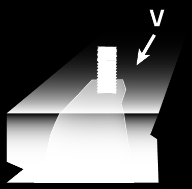
6 OPERATION GRAPHIC The 3D graphic is a visual aid built from all current user inputs. The graphic is independent of the currently active tab and will be shown for the material, geometry and load tabs. It is part of the final print out as well. The following properties can be changed directly using the graphic Anchor spacing Edge distance Concrete thickness Anchor plate dimensions Loads Tooltip A tooltip containing the property s name and unit will appear if you hover your mouse over any number in the graphic. To change a property using the graphic click on a number. A new input field will prompt you for the new value. Press the enter key to confirm it. In addition you can enable and disable edges by clicking on the corresponding concrete edge in the graphic. CONTROLS The graphic can be controlled by the buttons underneath it as well as with the mouse. Reset the graphic s rotation and zoom to default values. Zoom in to get a closer look on details. Keep this button pressed to continue zooming Zoom out to get a better overview Keep this button pressed to continue zooming. Pan Move the graphic in a vertical and/or horizontal direction by pressing and holding the left mouse button followed by moving the mouse. Release the left mouse button to stop moving the graphic. Rotate Rotate the graphic around its center by pressing and holding the the right mouse button followed by moving the mouse. Release the right mouse button to stop rotating the graphic. Zoom Zoom in by scrolling the mouse wheel up. Zoom out by scrolling the mouse wheel down. 6/40
7 OPERATION SECONDARY NAVIGATION The secondary navigation enables convenient navigation to the previous and following tab. It also contains any plausibility messages. Go to the previous tab. Go to the next tab. MESSAGES Every time user inputs are changed a plausibility check will be performed. If any errors are encountered they will be displayed in the secondary navigation s message area in red. All plausibility messages have to be resolved before the project can be calculated. The calculation then performs another plausibility check for each anchor. Since anchors differ in their properties there may be plausibility messages for some anchors but not for others. Any plausibility messages for the currently selected anchor will also be displayed in the secondary navigation s message area. See the calculation result topic for more details on per anchor plausibilities. List of possible plausibility messages Message Explanation Possible Resolutions The member thickness has to be larger than... The concrete member is too thin Increase the concrete thickness. The edge distance on the left hand side has to be equal to or larger than... The edge distance on the right hand side has to be equal to or larger than... The edge distance on the upper side has to be equal to or larger than... The edge distance on the lower side has to be equal to or larger than... Anchor outside of anchor plate no loads specified The selected installation condition is not valid for this anchor The selected temperature range is not valid for this anchor The selected seismic category is not valid for this anchor The selected installation direction is not valid for this anchor invalid edge distance invalid spacing distance invalid member thickness The left edge distance is too low. The right edge distance is too low. The top edge distance is too low. The bottom edge distance is too low. Anchors have to be within the anchor plate. The calculation is only possible if at least one load is defined. Some adhesive anchors are not approved for certain installation conditions. Some adhesive anchors are not approved for certain temperature ranges. Some anchors are not approved for seismic risk. Some anchors are not approved for for overhead or wall installations. One of the current edge distances is less than the selected anchor s minimum edge distance. One of the current anchor spacings is less than the selected anchor s minimum spacing. The current concrete thickness is less than the selected anchor s minimum concrete thickness. Increase the left edge distance or select another anchor. Make sure the anchor plate is completely on the concrete. Increase the right edge distance or select another anchor. Make sure the anchor plate is completely on the concrete. Increase the top edge distance or select another anchor. Make sure the anchor plate is completely on the concrete. Increase the bottom edge distance or select another anchor. Make sure the anchor plate is completely on the concrete. Reduce anchor spacing or increase anchor plate dimensions and check the eccentricity. Define at least one load. Change the installation condition or select another anchor. Change the temperature range or select another anchor. Disable seismic risk or select another anchor. Change the installation direction or select another anchor. Increase the lowest edge distance or select another anchor. Increase the lowest anchor spacing or select another anchor. Increase the concrete thickness or select another anchor. 7/40
8 OPERATION SOFTWARE UPDATE The Live Update will keep your Sika Anchor Calculation software up to date automatically. By default the update tool will automatically look for updates every seven days. If updates are available the new files will be downloaded automatically in the background. When you start or exit the software and updates are ready to be installed you will see the following prompt. Click Yes to install the update now. Click No to continue working normally. You will be prompted again at a later time. Since updates do not require administrative privileges you can perform updates at any time without involving your system administrator. Generally you won t have to access the update tool by yourself because everything happens automatically. If you would like to check for updates manually, change the update settings or just see the current status however you can launch the update tool from the software s main menu. The following information is available from the update s main window: Date you last searched for an update Date you last installed an update Status of automatic updates (enabled or disabled) To access the options menu click on the Options link. 8/40
9 OPERATION SOFTWARE UPDATE The options menu is split in two tabs: General and Proxy. The General tab contains configuration options for the update s behavior. When to check for updates Manually Automatically on program launch Automatically on system launch. When to download updates Manually Automatically (only while program is active) Automatically (always) How often to check for updates Every time Daily Weekly. Monthly When to prompt for update installation On system launch On program launch On program termination As soon as available When to show the notification tray icon Always When an update is in progress When user interaction is required In case an error occurred Never The Proxy tab contains proxy server configuration options. Generally you won t have to edit anything here. The update tool will try to detect the correct proxy settings automatically. If the update is unable to establish a connection to the internet you may have to manually configure the proxy options. In this case please contact your system administrator. They will know the correct proxy settings. 9/40


10 OPERATION PRIMARY NAVIGATION The primary navigation allows direct access to all available tabs Project information Material Geometry Load Result overview Print preview PROJECT INFORMATION The project information tab contains additional details about the project that do not influence the calculation. General project information Project name Project number or code Deadline Contractor, Sub-Contractor & Engineer Name of the company or person Name of the contact person Address Telephone number Fax number address Other notes related to the project can be added to the comments field. Examples include assumptions, hints and calculation requirements. 10/40
11 OPERATION MATERIAL The material tab deals with concrete, reinforcement and additional condition properties. Concrete class Select how much compressive strength the concrete can withstand. Anchor performance data may change depending on the concrete s compressive strength with higher values usually leading to higher capacities. Zone Select if the anchoring will be performed in cracked or uncracked concrete. While uncracked concrete leads to higher capacities it requires the concrete meets certain conditions which usually means further analysis has to be performed by the designer. Reinforcement of axial forces Select this option if Condition A for axial forces applies to the concrete in the area surrounding the anchorage as defined by ACI 318. Condition A usually applies if there is supplementary reinforcement to control splitting. This option influences the concrete breakout and pryout proofs. If this option is not selected Condition B is assumed and the calculation is carried out as if there was no reinforcement against axial forces. Reinforcement of Lateral forces Select this option if Condition A for Lateral forces applies to the concrete in the area surrounding the anchorage as defined by ACI 318. Condition A usually applies if there is an edge reinforcement with at least a #4 bar. Condition A may improve concrete edge failure capacity by up to 20%. If this option is not selected Condition B is assumed and the calculation is carried out as if there were no reinforcement against lateral forces. Enclosed stirrups with distance 4 inches This option may be selected in addition to Reinforcement of shear forces if the edge reinforcement is enclosed within stirrups spaced at not more than 4 inches. This will improve concrete edge failure capacity. Temperature range A temperature range is defined by a maximum short term temperature (first value) and a maximum long term temperature (second value). Anchor performance data may change depending on the selected temperature range. Some anchors may not be suitable for use in certain temperature ranges. Inspection Select whether continuous or periodic inspection is performed. This option influences the bond strength proof. (Not relevant to European Technical Assessments or for design according to EOTA TR029) The following values are available Continuous Periodic 11/40
12 OPERATION MATERIAL Installation conditions Select the condition the drill holes will be in during the anchor s installation. This option influences the bond strength proof. Some anchors may not be suitable for certain installation conditions. The following values are available Dry Water-saturated Water-filled Submerged (Not included in European Technical Assessments). GEOMETRY The geometry tab deals with anchor arrangements, concrete dimensions and anchor plate dimensions. Anchor arrangement Select either a single anchor or a group of two, three, four, six or eight anchors to define the general anchor arrangement. Some arrangement feature variants with slotted holes. Slotted holes The software offers the possibility to allocate slotted holes to one or more anchors. They allow more flexibility during the installation. Using this option you can influence which anchors will transmit shear forces. Usually base plates have slotted holes in order to assign all tension forces to certain anchors and all shear forces to the remaining anchors. Another application is anchoring near the concrete edge. With slotted holes near the edge you can prevent anchors from bearing shear forces directed towards the edge which may lead to a lower utilization capacity regarding concrete edge failure. Not all anchor arrangements allow for slotted holes and even if they do not every anchor can be allocated a slotted hole. The program limits slotted hole combinations to sensible variants. 12/40

13 OPERATION GEOMETRY Eccentricity of anchor plate Defines an offset between the anchor group s center and the anchor plate s center allowing you to change the anchor s positions on the anchor plate through y and z coordinates. This may lead to increased load which is taken into account by the software automatically. If you move anchors outside of the anchor plate you will see a plausibility message. The default values y = 0 and z = 0 mean the anchor groups s center is the same as the anchor plate s center. Anchor spacing Defines the distance between anchors. Depending on the selected anchor arrangement there may be up to four different spacing values or non at all for a single anchor. Please note that y represents horizontal spacing and z represents vertical spacing. Lower spacing values usually lead to higher anchor utilization with smaller design actions. Please be aware that an anchor s Evaluation report may define minimal anchor spacings. If you go below these values the anchor in question cannot be calculated and you will see a plausibility message. Angle The anchor arrangement may be rotated around its center in steps of 90. Slotted holes will be rotated as well. Use this option to gain access to additional variations of the selected anchor arrangement. Edge distances Defines which (if any) concrete edges have to be taken into consideration and what their respective edge distances are. By default the software assumes there are no relevant concrete edges. Click a check box on the left side to enable or disable a specific edge. You will be able define edge distances for enabled edges on the right side. Please note that the edge distance is defined as the distance from the concrete edge to the nearest anchor and not the distance to the nearest edge of the anchor plate. Smaller edge distances usually lead to higher anchor utilization with smaller design actions. An anchor s evaluation report may require a minimum edge distance that depends on the anchor s diameter and embedment depth. If one of the current edge distances is too low for the selected anchor you will see a plausibility message. Concrete thickness Defines the concrete member s thickness. An anchor s evaluation report may require a minimum concrete thickness that depends on the anchor s diameter and embedment depth. If the current concrete thickness is too low for the selected anchor you will see a plausibility message. It is assumed the anchor plate will be rectangular. Therefore its geometry can be defined by the anchor plate width, length (height) and thickness. The anchor plate width and length will be used for plausibility tests concerning anchor arrangement and edge distances. Anchors have to be within the anchor plate and the anchor plate has to be completely on concrete. 13/40
14 OPERATION LOAD The user is expected to input design loads. Design loads (also known as factored loads) may be obtained by calculating specific load combinations (live loads, dead loads,...). Please note that the software cannot calculate these load combinations. You will only be able to input loads and moments that can be absorbed by the selected anchor arrangement. Axial force Specify a load that acts perpendicular to the anchor plate along the x axis. Use positive values for tension ( pulling upwards) and negative values for compression ( pushing downwards). The 3D graphic displays arrows to indicate load direction. Lateral forces Specify loads that act parallel to the anchor plate. Use positive y values for forces that act from left to right along the y axis. Use positive z values for forces that act from bottom to top along the z axis. Use negative values to reverse the directions. The 3D graphic displays arrows to indicate load direction. Torques Specify a torsional moment that acts around the x axis and bending moments that act around the y and z axis. Use positive values for moments acting counterclockwise and negative values for moments acting clockwise. The 3D graphic displays arrows to indicate moment direction. Shear load conditions If anchors are used with built-up grout pads the nominal shear strength shall be multiplied by a 0.80 factor according to ACI 318 Appendix D Select this option to allow the software to modify the calculations accordingly. This does not affect designs according to EOTA TR029. Select which load combination method was used to calculate the design loads. The software will take the corresponding strength reduction factors and resistance modification factors into account. The following values are available ACI 318 Chapter 9.2 ACI 318 Appendix C ACI 318 Chapter 9.2 ( Strength and serviceability requirements - Required strength ) defines formulas to combine different load types (e.g. live loads, dead loads, wind loads,...) using load factors. This method was adapted from SEI/ASCE 7-02 (Structural Engineering Institute / American Society of Civil Engineers 7: Minimum Design Loads for Buildings and Other Structures) in 2002 to unify load factors and combinations. The old ACI 318 load factors and combinations from 1999 were revised and moved to ACI 318 Appendix C. They have evolved since the early 1960s and are considered to be reliable for concrete construction. If Appendix C is used it replaces the contents of Chapter 9.2 and 9.3. The load combination method defined in ACI 318 Appendix C.9.2 ( Alternative load and strength reduction factors - Required strength ) defines a similar method to Chapter 9.2 but is using other combination formulas and other load factors. For combinations with lateral loads, some designs will be different, but the results of either load combination method are considered acceptable. More details may be found in the actual ACI 318 code. For designs according to EOTA TR029, the combinations of dead and live loads inputted must take into consideration additional partial safety factors to account for the loading case. 14/40
.")

15 OPERATION RESULT OVERVIEW Filter By default all available anchors are calculated every time you click the Calculate button. The filter section allows you to focus on anchors with specific criteria. This speeds up the calculation and makes it easier to find the anchors your are interested in. Anchors may either be used to anchor a threaded rod or a reinforcement bar (rebar). Most anchors will be available in a fractional diameter (like 1/2 inch) but some may also be available with a metric thread (like M12). Anchor list The anchor list shows all anchors that conform to the selected filter criteria. Anchors can be sorted by name, material (steel), diameter and effective embedment depth (hef) by clicking on the corresponding table header. The anchor list can be filtered further by clicking the little filter icon in the table headers. You can select multiple values per filter and multiple filters can be active at the same time. Anchor details Below the anchor list you will see details for the currently selected anchor including a product picture and additional documents like the product data sheet from the catalog, a flyer / brochure to introduce the product. Click on a button to open the corresponding PDF document or link to the appropriate data. 15/40
, diameter, effective embedment depth (hef) and utilization by clicking on the corresponding table header. By default they are sorted by utilization.")

 will be shown in the message area. Resulting forces Below the result list you will see the resulting forces for the selected solution.")
16 OPERATION RESULT OVERVIEW Result list All results are shown in a table which includes details about the anchor, its percentage utilization and suitability. Anchors can be sorted by name, material (steel), diameter, effective embedment depth (hef) and utilization by clicking on the corresponding table header. By default they are sorted by utilization. Utilization is given by a percentage value and a color coded bar where green means acceptable and red means overloaded. Some anchors may not have a utilization value because they are not applicable for the parameters you entered. The results column shows a short color coded text to describe whether the selected anchor is acceptable, overloaded or not applicable. Select an anchor to see more details about the calculation. If the selected anchor is not applicable the reason(s) will be shown in the message area. Resulting forces Below the result list you will see the resulting forces for the selected solution. For every anchor in the arrangement the tension load Nu and the combined shear load (y + z axis) Vu is displayed. Calculation details Next to the resulting forces you will see calculation details in the form of a breakdown by failure mode (proof). The breakdown includes the allowed capacity and the actual utilization per proof. Utilization is given by a percentage value and a color coded bar where green means acceptable and red means overloaded. Additionally acceptable proofs are marked with a green tick whereas overloaded proofs are marked with a red cross. The controlling failure mode is the one with the highest utilization. Some proofs do not have a meaningful capacity value. A proof with the capacity 0 lb and utilization 0 % was not performed because the anchor s evaluation report defined it to not be controlling. 16/40


17 OPERATION PRINT PREVIEW The print preview tab shows a report containing all user inputs and calculation results as well as information about the selected anchor. You can print the report or save it as a PDF file. The print preview tab is only accessible after pressing the calculate button to calculate the current project. There are multiple buttons on the left side of the actual print preview. They allow you to control and configure the print out. Save report as a PDF file. Print the report By default the current date will be shown in the print out s header. You can specify a date which should be shown instead or you may opt to not show a date at all. The page and zoom buttons control which part of the print out will be visible in the preview area. Zoom Any project information you have entered will be part of the print out by default. If you wish to exclude the project information uncheck the box below. Show the whole page in the print preview area. Show the full page width in the print preview area. Show the print out in its actual size (100%). Page Go to the first page. Go to the previous page. Displays the current page number and number of total pages. Type in a page number to go directly to this page. Go to the next page Go to the last page. 17/40
 1 inch 25.4 mm 1 inch² 645.")
18 CALCULATION UNITS The software supports U.S. customary units and SI (metric) units. The currently selected system of measurement is visible in the main menu at any time. It affects all user inputs, the calculation and the printout. U.S. customary units Conversion from U.S. customary units to SI units U.S. customary units SI units (metric) 1 inch 25.4 mm 1 inch² mm² 1 psi MPa (N/mm²) 1 lb 4.45 N 1 ft*lb 1.36 * 10³ knm SI units (metrical) Conversion from SI units to U.S. customary units U.S. customary units SI units (metric) 1 mm inch 1 mm² 1.55 * 10³ inch² 1 MPa (N/mm²) 145 psi 1 N 0.22 lb 1 knm ft*lb Design loads The user is expected to input design loads. Design loads (also known as factored loads) may be obtained by calculating specific load combinations (live loads, dead loads,...). Please note that the software cannot calculate these load combinations. 18/40

 Steel proof Verification of adequate steel rod diameter Concrete Breakout (Tension) Concrete proof Influenced by concrete compressive strength and concrete reinforcement.")
19 CALCULATION ACI 318 The calculation is carried out in accordance with ACI 318 Appendix D and specific anchor s evaluation reports. ACI 318 defines nine different proofs for anchor calculations. Six of them relate to tension and three of them relate to shear. Depending on an anchor s evaluation report not all proofs have to be performed. In case of a seismic calculation some proofs are modified in accordance with ACI 318 and the anchor s evaluation report. Steel Failure (Tension) Steel proof Verification of adequate steel rod diameter Concrete Breakout (Tension) Concrete proof Influenced by concrete compressive strength and concrete reinforcement. Verification of adequate load bearing capacity of the concrete member in order to prevent the breakout of a concrete cone. 19/40

 Mortar proof Influenced by concrete")

20 CALCULATION Concrete Splitting (Tension) Concrete proof Influenced by concrete compressive strength, concrete reinforcement and geometry Verification that splitting does not occur, especially in thin concrete members Bond Failure (Tension) Mortar proof Influenced by concrete compressive strength, concrete reinforcement and conditions Verification of adequate bond in the mortar between threaded rod or rebar and concrete 20/40

 Concrete proof")


21 CALCULATION Steel Failure (Shear) Steel proof Verification of adequate shearing resistance within the steel diameter of the threaded rod or rebar Concrete Pryout (Shear) Concrete proof Influenced by concrete compressive strength and concrete reinforcement Verification of adequate load bearing capacity of the concrete member on the non-load side to prevent break-out of a concrete cone Concrete Breakout (Shear) Concrete proof Influenced by concrete compressive strength and concrete reinforcement Verification of adequate load bearing capacity at the edge in order to prevent concrete edge failure 21/40


: additional factor Ф")

22 CALCULATION Concrete Breakout (Shear) Concrete proof Influenced by concrete compressive strength and concrete reinforcement Verification of adequate load bearing capacity at the edge in order to prevent concrete edge failure Interaction The controlling tension and shear proofs have to be superimposed because there may be interaction between them. Adhesive anchors Concrete breakout (tension): additional factor Ф seismic = 0.75 Bond strength: additional factor αn,seis Bond strength: additional factor Ф seismic = 0.75 Steel failure (shear): additional factor αn,seis 22/40
 Water filled holes Maximum short term temperature: 110 F Maximum long")

23 EXAMPLE WORKFLOW EXAMPLE The aim of this example is to find a suitable anchor which will support the construction element with the parameters outlined below. Cracked concrete, 4000 psi compressive strength No concrete reinforcement Seismic category D Downward installation (in the floor) Water filled holes Maximum short term temperature: 110 F Maximum long term temperature: 68 F Periodic inspection Anchor plate: 10" x 7" x 0.25" Group of 4 anchors, spacing: 7" x 4" No relevant concrete edges Concrete thickness: 8" Tension Nu: 6000 lb Shear Vuy: 3000 lb Shear Vuz: 3000 lb Load combination according to ACI 318 Chapter 9.2 To get comfortable with using the software it is advised to follow along directly with the instructions. To begin start the software by using its desktop or start menu shortcut. The software will start with a default project which we will use as the baseline for this example. By clicking the New project button you can revert to the default project at anytime. If you made any changes so far you will be prompted to save or discard those changes before proceeding. Note: This step is entirely optional. You don t have to enter anything in the project information tab. Use the primary navigation to open the project information tab. In a real project you would probably enter all the contact information for contractor, subcontractor and engineer. In this example we will just enter a project name and number as seen below. This information will be shown in the print out later. Now it is time to input the actual calculation parameters. This topic is split up by tab of the primary navigation. Most of these values can be changed directly in the 3D graphic. In this example we will use the input area on the left side instead. 23/40

24 EXAMPLE WORKFLOW MATERIAL Use the primary navigation to open the material tab. The material tab deals with concrete and reinforcement properties. The material tab is split into boxes to group user inputs logically. We will go through the boxes from top top bottom. 1. Concrete (Normal Weight) The default project is initialized with the following values: To meet our requirements we have to change all values: Select 4000 psi from the Concrete Compressive Strength drop-down menu. Select Cracked Concrete (Tension Zone) from the Zone drop-down menu. 2. Concrete Reinforcement No changes are necessary here because the default assumption is that there is no reinforcement. To meet our requirements we have to change the values: Select 110 F 68 F from the Temperature range drop-down menu. The first value denotes maximum short term temperature while the second value denotes maximum long term temperature. Select Water-filled from the Installation Condition drop-down menu. Installation condition refers to the drill hole s condition during the installation process. 24/40
 which means the anchor will be located in the anchor plate s center.")

25 EXAMPLE WORKFLOW GEOMETRY Use the primary navigation to open the geometry tab. The geometry tab deals with anchor arrangements, concrete dimensions and anchor plate dimensions. 1. Anchor The default option is single anchor without eccentricity (displacement) which means the anchor will be located in the anchor plate s center. To meet our requirement (group of 4 anchors, spacing: 7 x 4 ) perform the following steps: Select Group of four without slotted holes from the anchor arrangement drop-down menu. Type 7 in the y1 input field and confirm by pressing the enter or return key. Type 4 in the z1 input field and confirm by pressing the enter or return key. Notice that the anchor spacing input fields only became visible after selecting an anchor arrangement with more than one anchor. Depending on the selected anchor arrangement there may be fewer or more anchor spacing input fields. 25/40


26 EXAMPLE WORKFLOW GEOMETRY 2. Edge Distances / Concrete Thickness The default project is initialized with the following values: Since we will not be considering any concrete edges in this example there is only one value to change: Type 8 in the Member thickness input field and confirm by pressing the enter or return key. 3. Anchor plate dimensions The default project is initialized with the following values: To meet our requirements we have to change all values that do not already match: Type 7 in the Anchor plate length input field and confirm by pressing the enter or return key. Type 0.25 in the Anchor plate thickness input field and confirm by pressing the enter or return key. Take note how the fraction 1/4 has to be entered using its decimal value of This applies to all values and input fields throughout the software. 26/40


27 EXAMPLE WORKFLOW LOAD 1. Load The default project is initialized without any loads: Enter the given design loads to match our requirements: Type 6000 in the Nu input field and confirm by pressing the enter or return key. Type 3000 in the Vuy input field and confirm by pressing the enter or return key. Type 3000 in the Vuz input field and confirm by pressing the enter or return key. 1. Load combinations No changes are necessary here because the default assumption is that loads were combined according to ACI 318 Chapter 9.2. As we have specified seismic category D we need to check the moderate to high seismic danger box. 27/40

28 EXAMPLE WORKFLOW ANCHOR SELECTION Now that all values have been entered click on the Calculate button to open the result overview tab and perform the actual calculations. The result overview tab shows all available anchors, documents for the selected anchor and calculation results. By default all available anchors will be calculated. Use filters (top left side) to narrow down the list of considered anchors. On your first calculation the anchor at the top of the left hand side list will be selected. After that your selection will be remembered between calculations. You have access to corresponding documents (like the ESR) for the selected anchor in the bottom left Anchor box. All results are shown in a table on the right side which includes details about the anchor, its percentage utilization and suitability. Generally you will want to select an anchor near the top of that table because by default suitable anchors with the highest utilization will be on top. They are followed by overloaded anchors and finally unsuitable anchors. See Calculation Results for more details. Below the result list you will see the resulting forces per anchor. Next to them you will see calculation details in the form of a breakdown by failure mode (proof). 28/40
29 EXAMPLE WORKFLOW PRINT OUT Use the primary navigation to open the print preview tab. The print preview tab shows a report containing all user inputs and calculation results as well as information about the selected anchor. Use the print options on the left side to configure the print out to your liking. There you will also find controls to navigate the preview displayed on the right. When you are satisfied print the report or save it as a PDF document. The print out contains all user inputs as well as the 3D graphic to illustrate the use case. Additionally there are details about the selected anchors and optionally your project information. The Verification sections contains details (including the used formulas) for every relevant proof. Do not forget to save your project file as well so you can recalculate or change it later without having to enter all values again. Use the Save button to do this. 29/40

30 REBAR CALCULATION PROGRAM GENERAL The user interface is divided into 5 areas: Rebar calculation is based on EOTA TR023 and Eurocode 2. It is only valid for the design of post-installed rebar connections and lap/splice lengths for products holding an ETA according to EOTA TR023. (1) Menu area (2) List of possible reinforcing bar diameters (3) Area for input and output (4) Preview window (5) Status bar The content of these areas will be described within the next chapters. Technical Report for Post Installed Rebar Connections TR23 The user interface is divided into 5 areas: (1) Menu area (2) List of possible reinforcing bar diameters (3) Area for input and output (4) Preview window (5) Status bar The content of these areas will be described within the next chapters. 30/40
31 REBAR CALCULATION PROGRAM MENU AREA In this area the most important icons can be found: Start new project Open project Save Project Save Project as Various information regarding the program. Amongst others you can find the version number of your software here. Switch languages. On principle, you can always switch languages. However, if the result overview or the print preview is being shown, the recalculation of the project is necessary. Calculate the current project. This icon might be deactivated if input data are missing or faulty. LIST OF POSSIBLE REINFORCING BAR DIAMETERS In this all diameters which can be used as post installed rebar connections according to the European Technical Assessment can be found in this list. Per default all diameters are selected and the software would carry out the calculations with all diameters. However, you can limit the selection in order to verify an existing rebar connection or to use only specific diameters. INPUT AND OUTPUT In this area up to five tabs may be visible Project information Numeric input Graphic input Result overview (this tab is not visible if no valid calculation results exist) Short result preview (this tab is not visible if no valid calculation results exist) Ideally, you should work through the software tabs from left to right. This will lead you through all relevant input parameters up to the print preview. The only exception to this is the tab Numeric input / Graphic input. Here you can choose whether you want to enter the data in table form or rather in a 3D environment. Of course you can switch between the two at any time. All changes will be refreshed simultaneously. The content of the input pages will be explained in the following chapters. 31/40
32 REBAR CALCULATION PROGRAM PROJECT INFORMATION Please enter all relevant project data in this form. The user name will be read from the Windows user name. You might change the date in order to date the project ahead or back. In comments you might add calculation assumptions, hints or assumptions. All these data will be shown at the beginning of the printout. 32/40
33 REBAR CALCULATION PROGRAM SYSTEM: SYSTEM SELECTION By clicking the application button in the system tab you can select an application. The software will then initialise a new graphic and the relevant inputs for the selected application. The applications available for selection are those given by EOTA TR023: 33/40

34 REBAR CALCULATION PROGRAM EXISTING REINFORCEMENT The existing reinforcement tab allows the user to input details of existing reinforcement including: Grade of steel The minimum cover Diameter of the steel select the diameter from the dropdown menu Shape coefficient of the rebar The condition of the bond area select the condition from the dropdown menu Rebar spacing By clicking the button displaying the currently selected steel grade it is possible to select a new steel grade from the menu: 34/40


35 REBAR CALCULATION PROGRAM The shape coefficient of the rebar may be changed by clicking the button next to shape coefficient displaying the currently selected alpha factors. 35/40


36 REBAR CALCULATION PROGRAM NEW REINFORCEMENT The new reinforcement tab allows the user to input details of new reinforcement to be installed including: Grade of steel The minimum cover If the new reinforcement is to be placed next to existing rebar The proportion of the rebars joined without lateral displacement The minimum cross sectional area of steel to be used for new reinforcement Define the rebar spacing By clicking the button displaying the currently selected steel grade it is possible to select a new steel grade from the menu: 36/40
37 REBAR CALCULATION PROGRAM LOAD The load tab allows the user to input load values acting on the new reinforcement. By checking the design load box the user can input the data for design loads. By un-checking the design load box the user can enter data for characteristic loads. The load combination may also be selected using the dropdown menu to chsose between the basic combination and extraordinary combination of loads. 37/40

38 REBAR CALCULATION PROGRAM RESULTS OVERVIEW The results overview tab displays all of the results for the selected parameters. The results shown in green are acceptable, whereas those shown in red are not acceptable. Error messages are also shown in the message area at the bottom of the screen to explain the reason why the selected result may be unacceptable. Click on a result to select it. This allows a print preview to be generated. An image of the selected product is shown in the bottom left corner of the screen. By clicking the button next to this the user can access the relevant documents for this product. 38/40

39 REBAR CALCULATION PROGRAM PRINT PREVIEW The print preview page allows the user to either directly print a hard copy of the selected solution or to save the calculation as a PDF file. The page / zoom area allows the user to zoom in and out of the calculation document or to skip through the pages of the calculation using the backwards and forwards arrows. It is possible to select the date shown on the calculation as either: no date (without), the current date (today) or a user defined date (select date) in the date area of the tab. By checking the print project data box, the user can choose to include the data entered previously in the project information tab in the calculation. 39/40
40 Sika Services AG Corporate Technical Department Speckstrasse 22 CH-8330 Pfäffikon ZH Switzerland Version given by: Marco B. Poltéra Phone: Fax: Mail: 40/40
HUS-H Screw Anchor. Technical data. Seismic design data. HUS-H Carbon steel screw anchor. HUS-H diameter 8, 10, 14. Seismic design data
 Technical data HUS-H Carbon steel screw anchor HUS-H diameter 8, 10, 14 10 / 011 Version 011-10 1 HUS-H screw anchor seismic design data Anchor version Carbon steel screw Benefits - Quick and easy setting
The following excerpt are pages from the North American Product Technical Guide, Volume 2: Anchor Fastening, Edition 16.
 The following excerpt are pages from the North American Product Technical Guide, Volume 2: Anchor Fastening, Edition 16. Please refer to the publication in its entirety for complete details on this product
Window Glass Design 5 According to ASTM E 1300
 A User s Guide to: Window Glass Design 5 According to ASTM E 1300 A product of: 1 Table of Contents Table of Contents List of Figures Chapter 1: Window Glass Design 5 1.1 Introduction 1.2 Features ii iv
TZ WEDGE ANCHOR FOR CRACKED AND UNCRACKED CONCRETE
 SECTION 2.2 PAGE 1 / 9 l DESCRIPTION UCAN TZ torque controlled mechanical expansion wedge anchors have a Category 1 classification. They are used to resist static, wind and seismic tension and shear loads
TABLE OF CONTENTS. INTRODUCTION... 5 Advance Concrete... 5 Where to find information?... 6 INSTALLATION... 7 STARTING ADVANCE CONCRETE...
 Starting Guide TABLE OF CONTENTS INTRODUCTION... 5 Advance Concrete... 5 Where to find information?... 6 INSTALLATION... 7 STARTING ADVANCE CONCRETE... 7 ADVANCE CONCRETE USER INTERFACE... 7 Other important
SpaceClaim Introduction Training Session. A SpaceClaim Support Document
 SpaceClaim Introduction Training Session A SpaceClaim Support Document In this class we will walk through the basic tools used to create and modify models in SpaceClaim. Introduction We will focus on:
SuccessFactors Learning: Scheduling Management
 SuccessFactors Learning: Scheduling Management Classroom Guide v 6.4 For SuccessFactors Learning v 6.4 Last Modified 08/30/2011 2011 SuccessFactors, Inc. All rights reserved. Execution is the Difference
Hilti KWIK HUS-EZ I (KH-EZ I) Internally Threaded Carbon Steel Screw Anchor
 Internally Threaded Carbon Steel Screw Anchor") Hilti KWIK HUS-EZ I (KH-EZ I) Internally Threaded Carbon Steel Screw Anchor Supplement to Hilti North American Product Technical Guide Volume 2: Anchor Fastening Technical Guide 2011 Edition 3.3. KWIK
Hilti KWIK HUS-EZ I (KH-EZ I) Internally Threaded Carbon Steel Screw Anchor Supplement to Hilti North American Product Technical Guide Volume 2: Anchor Fastening Technical Guide 2011 Edition 3.3. KWIK
Excel 2007 Basic knowledge
 Ribbon menu The Ribbon menu system with tabs for various Excel commands. This Ribbon system replaces the traditional menus used with Excel 2003. Above the Ribbon in the upper-left corner is the Microsoft
RFEM 5. Spatial Models Calculated acc. to Finite Element Method. of DLUBAL SOFTWARE GMBH. Dlubal Software GmbH Am Zellweg 2 D-93464 Tiefenbach
 Version July 2013 Program RFEM 5 Spatial Models Calculated acc. to Finite Element Method Tutorial All rights, including those of translations, are reserved. No portion of this book may be reproduced mechanically,
EUROPEAN ORGANISATION FOR TECHNICAL APPROVALS
 E TA TECHNICAL REPORT Design of Bonded Anchors TR 29 Edition June 27 EUROPEAN ORGANISATION FOR TECHNICAL APPROVALS TABLE OF CONTENTS Design method for bonded anchors Introduction..4 1 Scope...2 1.1 Type
What Do You Think? for Instructors
 Accessing course reports and analysis views What Do You Think? for Instructors Introduction As an instructor, you can use the What Do You Think? Course Evaluation System to see student course evaluation
Technical Notes 3B - Brick Masonry Section Properties May 1993
 Technical Notes 3B - Brick Masonry Section Properties May 1993 Abstract: This Technical Notes is a design aid for the Building Code Requirements for Masonry Structures (ACI 530/ASCE 5/TMS 402-92) and Specifications
ICC-ES Evaluation Report
 ICC-ES Evaluation Report ESR-2369 Reissued May 1, 2010 This report is subject to re-examination in one year. www.icc-es.org (800) 423-6587 (562) 699-0543 A Subsidiary of the International Code Council
CATIA Basic Concepts TABLE OF CONTENTS
 TABLE OF CONTENTS Introduction...1 Manual Format...2 Log on/off procedures for Windows...3 To log on...3 To logoff...7 Assembly Design Screen...8 Part Design Screen...9 Pull-down Menus...10 Start...10
CATIA Drafting TABLE OF CONTENTS
 TABLE OF CONTENTS Introduction...1 Drafting...2 Drawing Screen...3 Pull-down Menus...4 File...4 Edit...5 View...6 Insert...7 Tools...8 Drafting Workbench...9 Views and Sheets...9 Dimensions and Annotations...10
Welcome to the topic on creating key performance indicators in SAP Business One, release 9.1 version for SAP HANA.
 Welcome to the topic on creating key performance indicators in SAP Business One, release 9.1 version for SAP HANA. 1 In this topic, you will learn how to: Use Key Performance Indicators (also known as
Microsoft Word 2010. Revising Word Documents Using Markup Tools
 Microsoft Word 2010 Revising Word Documents Using Markup Tools Preface Word provides several markup tools that make document collaboration easy. Color coding, highlighting, and the ability maintain multiple
Introduction to Autodesk Inventor for F1 in Schools
 Introduction to Autodesk Inventor for F1 in Schools F1 in Schools Race Car In this course you will be introduced to Autodesk Inventor, which is the centerpiece of Autodesk s digital prototyping strategy
edgebooks Quick Start Guide 4
 edgebooks Quick Start Guide 4 memories made easy SECTION 1: Installing FotoFusion Please follow the steps in this section to install FotoFusion to your computer. 1. Please close all open applications prior
Generative Drafting. Page 1 1997 2001 DASSAULT SYSTEMES. IBM Product Lifecycle Management Solutions / Dassault Systemes
 Generative Drafting Page 1 Tutorial Objectives Description This Tutorial is an introduction to Generative Drafting. Message To show how CATIA V5 allows the user to automatically generate associative drafting
Advanced Microsoft Excel 2010
 Advanced Microsoft Excel 2010 Table of Contents THE PASTE SPECIAL FUNCTION... 2 Paste Special Options... 2 Using the Paste Special Function... 3 ORGANIZING DATA... 4 Multiple-Level Sorting... 4 Subtotaling
House Design Tutorial
 Chapter 2: House Design Tutorial This House Design Tutorial shows you how to get started on a design project. The tutorials that follow continue with the same plan. When we are finished, we will have created
Merging Labels, Letters, and Envelopes Word 2013
 Merging Labels, Letters, and Envelopes Word 2013 Merging... 1 Types of Merges... 1 The Merging Process... 2 Labels - A Page of the Same... 2 Labels - A Blank Page... 3 Creating Custom Labels... 3 Merged
Introduction to Autodesk Inventor for F1 in Schools
 F1 in Schools race car Introduction to Autodesk Inventor for F1 in Schools In this course you will be introduced to Autodesk Inventor, which is the centerpiece of Autodesk s Digital Prototyping strategy
Table of Contents. Part I Welcome. Part II Introduction. Part III Getting Started. Part IV The User Interface. Part V Quick Start Tutorials
 Contents I Table of Contents Part I Welcome 5 Part II Introduction 5 1 Overview... 5 2 Product... Levels 5 3 Technical... Support 6 4 Copyright... 7 Part III Getting Started 7 1 Installation... 7 2 Register...
Finance Reporting. Millennium FAST. User Guide Version 4.0. Memorial University of Newfoundland. September 2013
 Millennium FAST Finance Reporting Memorial University of Newfoundland September 2013 User Guide Version 4.0 FAST Finance User Guide Page i Contents Introducing FAST Finance Reporting 4.0... 2 What is FAST
DESIGN OF SLABS. 3) Based on support or boundary condition: Simply supported, Cantilever slab,
 Based on support or boundary condition: Simply supported, Cantilever slab,") DESIGN OF SLABS Dr. G. P. Chandradhara Professor of Civil Engineering S. J. College of Engineering Mysore 1. GENERAL A slab is a flat two dimensional planar structural element having thickness small compared
DESIGN OF SLABS Dr. G. P. Chandradhara Professor of Civil Engineering S. J. College of Engineering Mysore 1. GENERAL A slab is a flat two dimensional planar structural element having thickness small compared
Basic 2D Design Be sure you have the latest information!
 Basic 2D Design mastercam x getting started tutorials Basic 2D Design December 2011 Be sure you have the latest information! Information might have been changed or added since this document was published.
Hilti, Inc. 5400 South 122 nd East Avenue Tulsa, OK 74146. 1-800-879-8000 www.hilti.com
 Attached are page(s) from the 2014 Hilti North American Product Tech Guide. For complete details on this product, including data development, product specifications, general suitability, installation,
Applying a circular load. Immediate and consolidation settlement. Deformed contours. Query points and query lines. Graph query.
 Quick Start Tutorial 1-1 Quick Start Tutorial This quick start tutorial will cover some of the basic features of Settle3D. A circular load is applied to a single soil layer and settlements are examined.
SEISMIC DESIGN. Various building codes consider the following categories for the analysis and design for earthquake loading:
 SEISMIC DESIGN Various building codes consider the following categories for the analysis and design for earthquake loading: 1. Seismic Performance Category (SPC), varies from A to E, depending on how the
Web Intelligence User Guide
 Web Intelligence User Guide Office of Financial Management - Enterprise Reporting Services 4/11/2011 Table of Contents Chapter 1 - Overview... 1 Purpose... 1 Chapter 2 Logon Procedure... 3 Web Intelligence
Page 1 of 18 28.4.2008 Sven Alexander Last revised 1.3.2010. SB-Produksjon STATICAL CALCULATIONS FOR BCC 250
 Page 1 of 18 CONTENT PART 1 BASIC ASSUMPTIONS PAGE 1.1 General 1. Standards 1.3 Loads 1. Qualities PART ANCHORAGE OF THE UNITS.1 Beam unit equilibrium 3. Beam unit anchorage in front..1 Check of capacity..
Using Microsoft Word. Working With Objects
 Using Microsoft Word Many Word documents will require elements that were created in programs other than Word, such as the picture to the right. Nontext elements in a document are referred to as Objects
Embroidery Fonts Plus ( EFP ) Tutorial Guide Version 1.0505
 Tutorial Guide Version 1.0505") Embroidery Fonts Plus ( EFP ) Tutorial Guide Version 1.0505 1 Contents Chapter 1 System Requirements.................. 3 Chapter 2 Quick Start Installation.................. 4 System Requirements................
Embroidery Fonts Plus ( EFP ) Tutorial Guide Version 1.0505 1 Contents Chapter 1 System Requirements.................. 3 Chapter 2 Quick Start Installation.................. 4 System Requirements................
Chapter 9. Editing Features. Learning Objectives
 Chapter 9 Editing Features Learning Objectives After completing this chapter, you will be able to: Edit features. Edit sketches of the sketch based features. Edit the sketch plane of the sketch based features.
Concrete Design Manual
 The Reinforced Concrete Design Manual In Accordance with ACI 318-11 SP-17(11) Vol 2 ACI SP-17(11) Volume 2 THE REINFORCED CONCRETE DESIGN MANUAL in Accordance with ACI 318-11 Anchoring to concrete Publication:
Create a Poster Using Publisher
 Contents 1. Introduction 1. Starting Publisher 2. Create a Poster Template 5. Aligning your images and text 7. Apply a background 12. Add text to your poster 14. Add pictures to your poster 17. Add graphs
Introduction to CATIA V5
 Introduction to CATIA V5 Release 16 (A Hands-On Tutorial Approach) Kirstie Plantenberg University of Detroit Mercy SDC PUBLICATIONS Schroff Development Corporation www.schroff.com www.schroff-europe.com
Hilti HIT-HY 200 with rebar
 Hilti HIT-HY 200 Injection mortar system Benefits Hilti HIT- HY 200-A 500 ml foil pack (also available as 330 ml) Hilti HIT- HY 200-R 500 ml foil pack (also available as 330 ml) Static mixer rebar BSt
Hilti HIT-HY 150 MAX with rebar
 Hilti HIT-HY 150 MAX Injection mortar system Hilti HIT- HY 150 MAX 330 ml foil pack (also available as 500 ml and 1400 ml foil pack) Static mixer rebar BSt 500 S Benefits - suitable for non-cracked and
Chapter 1. Creating Sketches in. the Sketch Mode-I. Evaluation chapter. Logon to www.cadcim.com for more details. Learning Objectives
 Chapter 1 Creating Sketches in Learning Objectives the Sketch Mode-I After completing this chapter you will be able to: Use various tools to create a geometry. Dimension a sketch. Apply constraints to
DROOMS DATA ROOM USER GUIDE. www.drooms.com
 USER GUIDE www.drooms.com USER GUIDE Dear User, Whether simply reviewing documentation, sending queries during the due diligence process or administering a data room yourself, Drooms is the software solution
Decision Support AITS University Administration. Web Intelligence Rich Client 4.1 User Guide
 Decision Support AITS University Administration Web Intelligence Rich Client 4.1 User Guide 2 P age Web Intelligence 4.1 User Guide Web Intelligence 4.1 User Guide Contents Getting Started in Web Intelligence
Copyright 2006 TechSmith Corporation. All Rights Reserved.
 TechSmith Corporation provides this manual as is, makes no representations or warranties with respect to its contents or use, and specifically disclaims any expressed or implied warranties or merchantability
1. Application Overview... 3. 2. System Requirements... 3. 3. Installation... 3. 4. Splash Screen... 4. 5. Registration Screen...
 1 P a g e Table of Contents 1. Application Overview... 3 2. System Requirements... 3 3. Installation... 3 4. Splash Screen... 4 5. Registration Screen... 5 5.1 Registration... 5 6. Login Screen... 7 6.1
Internet Explorer 7. Getting Started The Internet Explorer Window. Tabs NEW! Working with the Tab Row. Microsoft QUICK Source
 Microsoft QUICK Source Internet Explorer 7 Getting Started The Internet Explorer Window u v w x y { Using the Command Bar The Command Bar contains shortcut buttons for Internet Explorer tools. To expand
Workflow Instructions Entering an Electronic Check Request
 2010 Workflow Instructions Entering an Electronic Check Request The Workflow Electronic Check Request process enables a user to create a payment request from his/her desktop and successfully route it to
Welcome to 360 Reporting... 3. Accessing 360 Reporting... 3 MicroEdge Support Program... 3. Using 360 Reporting... 4. Setting up Quick Find...
 Legal Notice The software described in this document is furnished under a license agreement. The software may be used or copied only in accordance with the terms of the agreement. No part of this document
Understand the Sketcher workbench of CATIA V5.
 Chapter 1 Drawing Sketches in Learning Objectives the Sketcher Workbench-I After completing this chapter you will be able to: Understand the Sketcher workbench of CATIA V5. Start a new file in the Part
Diameter. Swift Lift Round Recess Plug. Note: The diameter of the narrow recess plug is the same as the diameter of the round recess plug.
 P-5 The P-5 is hot forged from carbon steel. The formed head provis spherical seating that the Lifting Eye engages, while a disc-shaped foot is embedd in the concrete. Due to its being a forged part, the
ABOUT THIS DOCUMENT ABOUT CHARTS/COMMON TERMINOLOGY
 A. Introduction B. Common Terminology C. Introduction to Chart Types D. Creating a Chart in FileMaker E. About Quick Charts 1. Quick Chart Behavior When Based on Sort Order F. Chart Examples 1. Charting
NYS OCFS CMS Contractor Manual
 NYS OCFS CMS Contractor Manual C O N T E N T S CHAPTER 1... 1-1 Chapter 1: Introduction to the Contract Management System... 1-2 CHAPTER 2... 2-1 Accessing the Contract Management System... 2-2 Shortcuts
HVU with HAS/HAS-E rod adhesive anchor
 HVU with HAS/HAS-E rod HVU with HAS/HAS-E rod adhesive anchor Mortar system Benefits Hilti HVU foil capsule HAS HAS-R HAS-HCR rod - suitable for non-cracked concrete C 20/25 to C 50/60 - high loading capacity
User Guide. support.keytime.co.uk
 User Guide Contents Introduction... 3 Starting Personal Tax... 4 Sorting and Filtering Clients... 5 Print Summary and Print Proforma Letters... 5 Converting Returns from Previous Years... 6 Storing Client
Getting Started in Tinkercad
 Getting Started in Tinkercad By Bonnie Roskes, 3DVinci Tinkercad is a fun, easy to use, web-based 3D design application. You don t need any design experience - Tinkercad can be used by anyone. In fact,
Getting Started Guide
 3D Architect Home Designer Getting Started Guide Produced and published in the UK by Eleco Software Limited 2014 Eleco plc. All rights reserved. The software and hardware names and labels used in this
Virto SharePoint Gantt Chart App for Office 365 Release 1.0.3. User and Installation Guide
 Virto SharePoint Gantt Chart App for Office 365 Release 1.0.3 User and Installation Guide 2 Table of Contents OVERVIEW... 3 FEATURES LIST... 3 SYSTEM/DEVELOPER REQUIREMENTS... 3 OPERATING SYSTEM... 3 SERVER...
Handout: Word 2010 Tips and Shortcuts
 Word 2010: Tips and Shortcuts Table of Contents EXPORT A CUSTOMIZED QUICK ACCESS TOOLBAR... 2 IMPORT A CUSTOMIZED QUICK ACCESS TOOLBAR... 2 USE THE FORMAT PAINTER... 3 REPEAT THE LAST ACTION... 3 SHOW
How to Make the Most of Excel Spreadsheets
 How to Make the Most of Excel Spreadsheets Analyzing data is often easier when it s in an Excel spreadsheet rather than a PDF for example, you can filter to view just a particular grade, sort to view which
BIGPOND ONLINE STORAGE USER GUIDE Issue 1.1.0-18 August 2005
 BIGPOND ONLINE STORAGE USER GUIDE Issue 1.1.0-18 August 2005 PLEASE NOTE: The contents of this publication, and any associated documentation provided to you, must not be disclosed to any third party without
2013 Getting Started Guide
 2013 Getting Started Guide The contents of this guide and accompanying exercises were originally created by Nemetschek Vectorworks, Inc. Vectorworks Fundamentals Getting Started Guide Created using: Vectorworks
Submittal Information
 Wedge SPECIFIED FOR ANCHORAGE INTO CONCRETE Wedge anchs feature a stainless steel expansion clip, threaded stud body, nut and washer. Anch bodies are made of plated carbon steel, hot-dipped galvanized
SAP Business Intelligence ( BI ) Financial and Budget Reporting. 7.0 Edition. (Best Seller At Least 43 copies Sold)
 Financial and Budget Reporting. 7.0 Edition. (Best Seller At Least 43 copies Sold)") SAP Business Intelligence ( BI ) Financial and Budget Reporting 7.0 Edition (Best Seller At Least 43 copies Sold) November 2011 Table of Contents Log In... 3 Initial Variable Screen... 5 Multiple / Single
SAP Business Intelligence ( BI ) Financial and Budget Reporting 7.0 Edition (Best Seller At Least 43 copies Sold) November 2011 Table of Contents Log In... 3 Initial Variable Screen... 5 Multiple / Single
525 South 29 th Street. Harrisburg, PA 17104. Learning Management System User s Guide
 525 South 29 th Street Harrisburg, PA 17104 Learning Management System User s Guide July 2015 1 Table of Contents User Accounts Overview 3 Changing your Email address 3 Changing your Password 3 Changing
DATA COLLECTION GUIDANCE
 COMPLETING THE EARLY YEARS FOUNDATION STAGE PROFILE 2016 DATA COLLECTION GUIDANCE Please ensure you have completed the Import Routine for all Key Stages prior to starting the following processes 1 2 CONTENTS
Using Microsoft Project 2000
 Using MS Project Personal Computer Fundamentals 1 of 45 Using Microsoft Project 2000 General Conventions All text highlighted in bold refers to menu selections. Examples would be File and Analysis. ALL
Microsoft Office Excel 2007 Key Features. Office of Enterprise Development and Support Applications Support Group
 Microsoft Office Excel 2007 Key Features Office of Enterprise Development and Support Applications Support Group 2011 TABLE OF CONTENTS Office of Enterprise Development & Support Acknowledgment. 3 Introduction.
WHAT S NEW IN WORD 2010 & HOW TO CUSTOMIZE IT
 WHAT S NEW IN WORD 2010 & HOW TO CUSTOMIZE IT The Ribbon... 2 Default Tabs... 2 Contextual Tabs... 2 Minimizing and Restoring the Ribbon... 3 Customizing the Ribbon... 3 A New Graphic Interface... 5 Live
Kentico CMS 7.0 User s Guide. User s Guide. Kentico CMS 7.0. 1 www.kentico.com
 User s Guide Kentico CMS 7.0 1 www.kentico.com Table of Contents Introduction... 4 Kentico CMS overview... 4 Signing in... 4 User interface overview... 6 Managing my profile... 8 Changing my e-mail and
Excel -- Creating Charts
 Excel -- Creating Charts The saying goes, A picture is worth a thousand words, and so true. Professional looking charts give visual enhancement to your statistics, fiscal reports or presentation. Excel
Single Property Website Quickstart Guide
 Single Property Website Quickstart Guide Win More Listings. Attract More Buyers. Sell More Homes. TABLE OF CONTENTS Getting Started... 3 First Time Registration...3 Existing Account...6 Administration
Excel Reports and Macros
 Excel Reports and Macros Within Microsoft Excel it is possible to create a macro. This is a set of commands that Excel follows to automatically make certain changes to data in a spreadsheet. By adding
Tutorial: 2D Pipe Junction Using Hexa Meshing
 Tutorial: 2D Pipe Junction Using Hexa Meshing Introduction In this tutorial, you will generate a mesh for a two-dimensional pipe junction, composed of two inlets and one outlet. After generating an initial
ETABS. Integrated Building Design Software. Concrete Shear Wall Design Manual. Computers and Structures, Inc. Berkeley, California, USA
 ETABS Integrated Building Design Software Concrete Shear Wall Design Manual Computers and Structures, Inc. Berkeley, California, USA Version 8 January 2002 Copyright The computer program ETABS and all
3D Viewer. user's manual 10017352_2
 EN 3D Viewer user's manual 10017352_2 TABLE OF CONTENTS 1 SYSTEM REQUIREMENTS...1 2 STARTING PLANMECA 3D VIEWER...2 3 PLANMECA 3D VIEWER INTRODUCTION...3 3.1 Menu Toolbar... 4 4 EXPLORER...6 4.1 3D Volume
Detailing of Reinforcment in Concrete Structures
 Chapter 8 Detailing of Reinforcment in Concrete Structures 8.1 Scope Provisions of Sec. 8.1 and 8.2 of Chapter 8 shall apply for detailing of reinforcement in reinforced concrete members, in general. For
Guide To Creating Academic Posters Using Microsoft PowerPoint 2010
 Guide To Creating Academic Posters Using Microsoft PowerPoint 2010 INFORMATION SERVICES Version 3.0 July 2011 Table of Contents Section 1 - Introduction... 1 Section 2 - Initial Preparation... 2 2.1 Overall
DIVISION: 04 00 00 MASONRY SECTION: 04 05 19.16 MASONRY ANCHORS REPORT HOLDER: HILTI, INC. 7250 DALLAS PARKWAY, SUITE 1000 PLANO, TEXAS 75024
 0 ICC-ES Report ICC-ES (800) 423-6587 (562) 699-0543 www.icc-es.org 000 Most Widely Accepted and Trusted ESR-3342 Reissued 08/2015 This report is subject to renewal 08/2017. DIVISION: 04 00 00 MASONRY
WebFOCUS BI Portal: S.I.M.P.L.E. as can be
 WebFOCUS BI Portal: S.I.M.P.L.E. as can be Author: Matthew Lerner Company: Information Builders Presentation Abstract: This hands-on session will introduce attendees to the new WebFOCUS BI Portal. We will
European Technical Assessment ETA-10/0153 of 10/06/2015
 ETA-Danmark A/S Göteborg Plads 1 DK-2150 Nordhavn Tel. +45 72 24 59 00 Fax +45 72 24 59 04 Internet ww.etadanmark.dk Authorised and notified according to Article 29 of the Regulation (EU) No 305/2011 of
Regional Drought Decision Support System (RDDSS) Charting Tools Help Documentation
 Charting Tools Help Documentation") Regional Drought Decision Support System (RDDSS) Charting Tools Help Documentation The following help documentation was prepared to give insight to the basic functionality of the charting tools within
Regional Drought Decision Support System (RDDSS) Charting Tools Help Documentation The following help documentation was prepared to give insight to the basic functionality of the charting tools within
Virto SharePoint Gantt Chart Web Part for SharePoint 2013 Release 4.3.0. User and Installation Guide
 Virto SharePoint Gantt Chart Web Part for SharePoint 2013 Release 4.3.0 User and Installation Guide Table of Contents FEATURES LIST... 3 SYSTEM/DEVELOPER REQUIREMENTS... 3 OPERATING SYSTEM... 3 SERVER...
Egcobox Software Manuel Version 2.0. 2007-2010 Max Frank GmbH & Co. KG
 Egcobox Software Manuel Version 2.0 2007-2010 Max Frank GmbH & Co. KG Egcobox Software Contents Page Contents 3-4 Overview 5-13 Example calculation type 1: cantilever balcony 14-15 Language and standard
Microsoft Word 2010. Quick Reference Guide. Union Institute & University
 Microsoft Word 2010 Quick Reference Guide Union Institute & University Contents Using Word Help (F1)... 4 Window Contents:... 4 File tab... 4 Quick Access Toolbar... 5 Backstage View... 5 The Ribbon...
Registry Tuner. Software Manual
 Registry Tuner Software Manual Table of Contents Introduction 1 System Requirements 2 Frequently Asked Questions 3 Using the Lavasoft Registry Tuner 5 Scan and Fix Registry Errors 7 Optimize Registry
Sonatype CLM Server - Dashboard. Sonatype CLM Server - Dashboard
 Sonatype CLM Server - Dashboard i Sonatype CLM Server - Dashboard Sonatype CLM Server - Dashboard ii Contents 1 Introduction 1 2 Accessing the Dashboard 3 3 Viewing CLM Data in the Dashboard 4 3.1 Filters............................................
Adobe Dreamweaver CC 14 Tutorial
 Adobe Dreamweaver CC 14 Tutorial GETTING STARTED This tutorial focuses on the basic steps involved in creating an attractive, functional website. In using this tutorial you will learn to design a site
SAS BI Dashboard 3.1. User s Guide
 SAS BI Dashboard 3.1 User s Guide The correct bibliographic citation for this manual is as follows: SAS Institute Inc. 2007. SAS BI Dashboard 3.1: User s Guide. Cary, NC: SAS Institute Inc. SAS BI Dashboard
HUS-HR, CR Screw anchor, stainless steel
 HUS-HR, CR Screw anchor, Anchor version HUS-HR 6 / 8 / 10 / 14 Stainless steel concrete Screw with hexagonal head HUS-CR 10 Stainless steel concrete screw with countersunk head Benefits - High productivity
User Guide. SysMan Utilities. By Sysgem AG
 SysMan Utilities User Guide By Sysgem AG Sysgem is a trademark of Sysgem AG. Other brands and products are registered trademarks of their respective holders. 2013 Sysgem AG, Lavaterstr. 45, CH-8002 Zürich,
HTML Code Generator V 1.0 For Simatic IT Modules CP 443-1 IT, 343-1 IT, 243-1 IT
 HTML Code Generator V 1.0 For Simatic IT Modules CP 443-1 IT, 343-1 IT, 243-1 IT Manual This manual and program are freeware. Every user can use, copy or forward this program and documentation FREE OF
Introduction to the TI-Nspire CX
 Introduction to the TI-Nspire CX Activity Overview: In this activity, you will become familiar with the layout of the TI-Nspire CX. Step 1: Locate the Touchpad. The Touchpad is used to navigate the cursor
Snagit 10. Getting Started Guide. March 2010. 2010 TechSmith Corporation. All rights reserved.
 Snagit 10 Getting Started Guide March 2010 2010 TechSmith Corporation. All rights reserved. Introduction If you have just a few minutes or want to know just the basics, this is the place to start. This
SolidWorks Tutorial 3 MAGNETIC BLOCK
 SolidWorks Tutorial 3 MAGNETIC BLOCK Magnetic Block In this exercise you will make a magnetic block. To do so, you will create a few parts, which you will assemble. You will learn the following new applications
USER S MANUAL. AXIS Mobile Monitor
 USER S MANUAL AXIS Mobile Monitor AXIS Mobile Monitor Overview Main window Main menu Find Devices Find Devices menu Monitor window Monitor menu Sequence window Sequence menu How to Use AXIS Mobile Monitor
An Informational User Guide for: Web Conferencing
 Allows You to: Manage your audio conference online using easy point and click conference commands Show slide presentations and graphics to meeting participants Show your desktop to meeting participants
Section #13 Pictorial Table Of Contents. The Caster. Top & Bottom Shelves. Pages 617-623 Page 624 Page 625 Pages 626-628 Pages 629-633
 AQX Introduction Section # Pictorial Table Of Contents Completed Shop Cart Step-by-Step Tutorial The Caster The Leg Fractional The Lower Cross Member Machining w/ Access Holes AutoQuoterX Page 610 Page
Information Technology. Introduction to Vista
 Information Technology Introduction to Vista The Vista Login Screen. Vista, like XP, remembers the previous user. After logging in, you can select your own picture. For a different user to login, click