Programmable Room Thermostat With RF
|
|
|
- Quentin Moody
- 7 years ago
- Views:
Transcription


1 Programmable Room Thermostat With RF Instruction Manual Model No RT500RF
2 PRODUCT COMPLIANCE This product complies with the essential requirements of the following EC Directives: Electro-Magnetic Compatibility directive 2004/108/EC Low Voltage Directive 2006/95/EEC EC Marking directive 93/68/EEC SAFETY INFORMATION These instructions are applicable to the SALUS Controls model stated on the front cover of this manual only, and must not be used with any other make or model. These instructions are intended to apply in the United Kingdom only, and should be followed along with any other statutory obligations. This accessory must be fitted by a Competent person, and installation must comply with the guidance provided in the current editions of BS7671 (IEE Wiring Regulations) and Part P of the Building Regulations. Failure to comply with the requirements of these publications could lead to prosecution. Always isolate the AC Mains supply before opening or removing the unit from the wall or wall box. When fitting batteries don t mix old and new batteries together. Do not use rechargable batteries. Please leave these instructions with the end user where they should be kept in a safe place for future reference. 2 RT500RF INSTRUCTION MANUAL
3 INTRODUCTION What is a programmable room thermostat?... an explanation for householders A programmable room thermostat is both a programmer and a room thermostat. A programmer allows you to set On and Off time periods to suit your own lifestyle. A room thermostat works by sensing the air temperature, switching on the heating when the air temperature falls below the thermostat setting, and switching it off once this set temperature has been reached. So, a programmable room thermostat lets you choose what times you want the heating to be on, and what temperature it should reach while it is on. It will allow you to select different temperatures in your home at different times of the day (and days of the week) to meet your particular needs. Turning a programmable room thermostat to a higher setting will not make the room heat up any faster. How quickly the room heats up depends on the design of the heating system, for example, the size of boiler and radiators. Neither does the setting affect how quickly the room cools down. Turning a programmable room thermostat to a lower setting will result in the room being controlled at a lower temperature, and saves energy. The way to set and use your programmable room thermostat is to find the lowest temperature settings that you are comfortable with at the different times you have chosen, and then leave it alone to do its job. The best way to do this is to set low temperatures first, say 18 C, and then turn them up by one degree each day until you are comfortable with the temperatures. You won t have to adjust the thermostat further. Any adjustments above these settings will waste energy and cost you more money. If your heating system is a boiler with radiators, there will usually be only one programmable room thermostat to control the whole house. But you can have different temperatures in individual rooms by installing thermostatic radiator valves (TRVs) on individual radiators. If you don t have TRVs, you should choose a temperature that is reasonable for the whole house. If you do have TRVs, you can choose a slightly higher setting to make sure that even the coldest room is comfortable, then prevent any overheating in other rooms by adjusting the TRVs. The time on the programmer must be correct. Some types have to be adjusted in spring and autumn at the changes between Greenwich Mean Time and British Summer Time. RT500RF INSTRUCTION MANUAL 3

.")

4 You may be able to temporarily adjust the heating programme, for example, Override, Advance or Boost. These are explained in the manufacturer s instructions. Programmable room thermostats need a free flow of air to sense the temperature, so they must not be covered by curtains or blocked by furniture. Nearby electric fires, televisions, wall or table lamps may prevent the thermostat from working properly. INTRODUCTION The RT500RF from SALUS Controls is a stylish and accurate 5/2 or 7 day programmable electronic thermostat with a large, easy to read Liquid Crystal Display (LCD). This programmable thermostat has been specifically designed to be used for both Volt Free and AC heating applications. This programmable thermostat can replace most common residential thermostats and is designed to be used with electric, gas or oil heating control systems. Unlike ordinary single unit design thermostats, this is a new type of thermostat separating the operational functions into two units. The Receiver is used for wiring connections and heat on/off control. The Control Centre provides the user interface and temperature sensing / control. The two units are linked together by a Radio Frequency (RF) signal. Features Volt free switching option 5/2 or 7 day programming flexibility Built-in start up programming for quick installation Frost protection Large, easy to read LCD with blue backlight Burner on symbol Easy to use programming User friendly 4 RT500RF INSTRUCTION MANUAL
5 INSTALLATION Please read the important safety information at the start of this manual before you begin to install the device. The RT500RF Control Centre is easily installed using the Industry Standard back plate supplied with the unit this is used purely for mounting purposes, as no wiring is needed for the Control Centre. The back plate can be mounted directly to the wall surface. The ideal position to locate the RT500RF Control Centre is about 1.5m above floor level. It should be mounted in a location where the thermostat is accessible, reasonably lit and free from extremes of temperature and draughts. Do not mount the thermostat on an outside wall, above a radiator or in a location where it may be subjected to direct sunlight. To ensure trouble free operation of the Radio Frequency (RF) signal, always ensure that the programmable thermostat is mounted away from any possible sources of interference (such as radios, TV sets, computers, etc.), and is not mounted on or in close proximity to large metal objects. Installing the RT500RF in enclosed areas such as cellars and basements is not recommended. CONNECTING THE RT500RF RECEIVER NOTE: All electrical installation work should be carried out by a suitably qualified Electrician or other competent person. If you are not sure how to install this programmable thermostat consult either with a qualified electrician, heating engineer or your boiler / heating system supplier for advice on how to continue. RT500RF INSTRUCTION MANUAL 5
.")

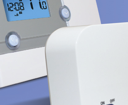
6 The RT500RF Receiver should be mounted in a suitable location that is both accessible for the connection of mains and control wiring, and allows good reception of the RF signal. The Receiver needs a 230V AC mains supply to operate, and this should be fused appropriately (13A max.). The Receiver should be mounted in a location where it will not come into contact with water, moisture or condensation. The Receiver On/Off switch is accessible from the front face of the Receiver, as shown in this picture: On the front cover of the Receiver you will see that there is the On/Off switch and two Light Emitting diodes (LEDs). The switch allows you to turn off the Receiver if necessary to prevent it calling for heat. The bottom LED (red) will illuminate when the switch is in the On position and the unit is receiving power. The top LED (green) illuminates when the Receiver unit is receiving a heat call transmission from the Control Centre. The wiring terminals and RF Address Code setting DIP switches are located on the rear of the Receiver, as shown in this picture: RECEIVER WIRING TERMINALS Terminal Identifier Description 1 NO Normally Open [N/O] 2 COM Linked Live feed (230V AC heating applications only) 3 L Live feed (230V AC) 4 N Neutral 6 RT500RF INSTRUCTION MANUAL
7 TYPICAL WIRING INSTALLATIONS a.230v AC Installation Notes: Receiver unit should have a permanent 230V AC main supply Confirm that the Boiler has an external thermostat loop and is configured for 230V switching If the boiler has two terminals for the thermostat, remove the link from the boiler b. 24V Installation Notes: Receiver unit should have a permanent 230V AC main supply Confirm that the Boiler has an external thermostat loop and is NOT configured for 230V switching If the boiler has two terminals for the thermostat, remove the link from the boiler RT500RF INSTRUCTION MANUAL 7

8 CONTROL CENTRE JUMPER SETTINGS Changes to the jumper settings should only be made by the Engineer carrying out the installation or other qualified person. The installer should select the jumper positions required if changes need to be made to the factory default settings. These jumpers are found on the rear of the Control Centre. Jumper Function Program Jumper for 5-2 (factory default setting) or 7 individual days programming. Span Movable jumper for selecting temperature span of ± 0.5 C (factory default setting) or ± 1.0 C 1,2,3,4,5 Removable jumpers for altering the RF address code when used in conjunction with the corresponding DIP switch on the Receiver. NOTE: The Reset button must be pressed after changing jumper positions. 8 RT500RF INSTRUCTION MANUAL

9 RF ADDRESS CODE SETTING If there is another unit being used nearby, e.g. in the next house or as part of a multiple installation, your Receiver may be fault triggered by the other Control Unit. You can change the RF Address Code to help prevent this problem. Each Receiver can only respond to RF transmissions from a Control Centre that has the same RF address code setting. Disconnect any AC power to the Receiver, and remove the batteries from the Control Centre before attempting any adjustment of the RF Address Code switches and jumpers. If you are not sure how to carry out this operation correctly, consult either with a qualified electrician or heating engineer. To adjust the RF address code of the Receiver, simply push up one or more of the 5 DIP switch levers on the DIP switch bank located on the back of the receiver (the levers are numbered 1 to 5 from bottom to top, as shown in the picture below), and then make a note of the setting of each switch: RT500RF INSTRUCTION MANUAL 9

10 To adjust the RF address code of the Control Centre, remove one or more of the jumper caps located on the back of the unit (labelled 1,2,3,4 and 5, and shown in the picture below) so that the jumper settings match the settings made on the receiver: For example, if the DIP switches on the Receiver were set as follows: 1 - ON 2 - OFF 3 - OFF 4 - OFF 5 - ON Then you would need to remove jumper caps 2, 3 and 4 on the Control Centre to make sure that they are both set with the same RF address code. Please make sure that you keep any of the jumper caps you remove in a safe place, in case you later need to change the RF address setting again. You must press RESET on the Control Centre after making any changes to the RF address code settings. 10 RT500RF INSTRUCTION MANUAL
11 TESTING THE RF TRANSMISSION It is important to site both the Receiver and Control Centre in locations where the RF signal cannot be interrupted. The receiving range between Control Centre and Receiver is approximately 30 metres indoors, however many factors can affect the RF transmission and shorten the operating distance, e.g. shielding by thick walls, foil back plasterboard, metal objects such as filing cabinets, general RF interference, and so on. The range is generally large enough for most household applications, but it is advisable to test the RF transmission from the intended Control Centre location to the Receiver location before fixing the Control Centre to the wall. To check the RF reception, follow the following steps: 1. Press the UP button on the Control Centre until the set point temperature is higher than room temperature by a few degrees. 2. Wait for a few seconds. The Burner on (heat call) indicator should appear on the bottom left of the LCD on the Control Centre. 3. Check the green LED on the receiver unit - it should be lit. 4. Press the DOWN button to adjust the set point temperature to be lower than room temperature. 5. Wait for a few seconds, and the Burner on (heat call) indicator should disappear and the green LED should switch off. 6. If at step 3 the green LED is not illuminated, press the RESET button on the Control centre and try to place the Control Centre closer to the Receiver. 7. Repeat steps 1 to 5. If you are unable to get a stable RF connection between the Receiver and Control Centre, check that the Receiver is both switched on and has a mains supply (red LED lit). If this isn t the problem you can also alter the RF address code by following the RF Address Code Setting section of this manual, and then repeat steps 1 to 5 (note that the RESET button on the Control Centre should be pressed after altering the address code). RT500RF INSTRUCTION MANUAL 11
12 MULTIPLE THERMOSTAT INSTALLATIONS If you are using more than one RT500RF programmable thermostat in the same installation, be sure that there is at least a 1 metre gap between receiver units to avoid crosstalk and other RF interference. When installing multiple thermostats, you should assign different RF address codes for each RT500RF by following the instructions in the RF Address Code Setting section of this manual. Each RT500RF should be introduced to the installation one at a time with all other Receiver units switched off. Also make sure that the batteries are removed from all other Control Centres. Install each unit following the Testing the RF Transmission section above - once you are happy with the operation of one unit you can install the next. Once all the RT500RF units have been installed, if one unit then seems to function abnormally, try changing the RF address code of that unit s Control Centre and its corresponding Receiver, making sure that the new RF address code is different to all others in the installation. The control centre sends RF On/Off signals every 10 minutes to ensure the Receiver is in the correct state. If for some reason the first RF signal is interrupted you may notice the Control Centre has stopped or started calling for heat but the Receiver hasn t switched. Simply wait 10 minutes until the next RF signal is transmitted and the receiver unit should then switch correctly. 12 RT500RF INSTRUCTION MANUAL
13 AFTER INSTALLATION The following table shows the settings of the RT500RF programmable thermostat after Power on, or after RESET is pressed: Function Status After Reset or Power On Operation Mode Normal mode Room Temperature 22.0 C, updated within 5 seconds C indicator On Clock 12:00 AM/PM indicator AM Day of Week indicator M Program Default factory setting Set Point Temperature Default factory setting Program Number indicator 1 SET indicator Off PROG indicator Off Frost Protection indicator Off Heat indicator Off Low-Battery Warning indicator Off, updated within 5 seconds Output Relay Off After Power on, the thermostat will operate in Normal mode (Normal mode is when the thermostat is displaying the room temperature): The set point temperature is reset to the default setting The room temperature display is updated within 5 seconds The control process starts The programme number is updated to indicate the running program If the Reset Button is pressed, the RT500RF will behave in the same way as described above, except that any previously saved user settings stored in the internal memory will be deleted and overwritten with the default settings, and all programmable thermostat control settings will be returned to default values. RT500RF INSTRUCTION MANUAL 13


14 USER INTERFACE AND CONTROLS The status and operation of the RT500RF is clearly shown on the large backlit Liquid Crystal Display (LCD). This display allows the user to see at a glance the current status of the heating system, the current time and day of the week, as well as a clear indication of the current room temperature. There are few user controls for the RT500RF, making the programmable thermostat very easy to operate. These controls are shown below, along with a description of each of their functions. USER CONTROL FUNCTION SUMMARY Key / Operation Symbol Functions UP key Increases the selected setting DOWN key Decreases the selected setting BACKLIGHT / Manually turns on the LCD backlight FROST key for 5 seconds, or activates / deactivates Frost Protection SELECT key Selects a clock or programme setting SET key RESET button 14 Sets a clock or programme setting Resets the programmable thermostat to default (original factory) settings RT500RF INSTRUCTION MANUAL
15 OPERATION The RT500RF is configured and adjusted by the use of a minimal number of user controls, and an intuitive user interface. The backlit Liquid Crystal Display (LCD) gives a highly visible, easily readable indication of the programmable thermostat status. SETTING THE TIME Press and hold SET and SELECT when the RT500RF is in Normal mode for a few seconds to enter the Clock setting mode. Release both keys and the display will look like the image below: The Time and Day are displayed along with a SET indicator, with all other indicators cleared from the display. The hour part of the time is flashing to indicate that it is the currently selected item and is ready to be adjusted. Press the UP or DOWN keys to increase or decrease the hour setting the selected item will stop flashing while a key is pressed, and will resume flashing when you release the key. Press the SELECT key to select the minutes section of the time. Set the minutes in the same way as the hour by using the UP and DOWN keys. Press SELECT again to select the Day, and again change the setting with the UP and DOWN keys. Press the SET key to confirm the new time and day settings. This will store the changes and return the RT500RF to Normal mode. The RT500RF Control Centre will also return to Normal mode (and save the clock settings) if no keys are pressed for more than 15 seconds. RT500RF INSTRUCTION MANUAL 15

16 PROGRAMMING THE RT500RF The RT500RF offers great versatility with its programming options, allowing the user to programme the unit to operate on a 5/2 or 7 day control cycle. The programmable thermostat has a default set of Programmes that have been designed to meet the needs of most users. If these default programmes are not suitable for your particular situation, reprogramming the RT500RF with your own settings is a very straightforward operation. Selection of the default programming mode (5/2 or 7 day) is made by changing the jumper setting on the rear of the RT500RF Control Unit, as previously described within the Installation section of this manual. 5/2 DAY MODE 5/2 day mode is the default programming mode for the RT500RF. With this mode selected, five different sets of time and set point temperatures can be set for Weekdays or Weekends. To review or change a programme, press the SET key when the RT500RF is in Normal mode. This will change the unit status to Programme Setting mode. The LCD display will display programme number 1 and SET PROG, with all other indicators cleared. The weekdays will be flashing to indicate they are the selected item and are ready to be adjusted: 16 RT500RF INSTRUCTION MANUAL

17 Press the UP or DOWN key to select the programme set for either Weekday or Weekend to be reviewed or adjusted. Pressing the SET key at any time when in programming mode will return the RT500RF into Normal mode. Press the SELECT key to confirm the Weekday or Weekend selection. Once this is set, the Hour will flash to indicate that it is the selected item and is the next item to be adjusted: Press the UP or DOWN key to adjust the hour setting to the desired value, and confirm your selection by pressing the SELECT key. Pressing the SELECT key allows you to step through each of the items to be reviewed or adjusted within the programmes in the following sequence: Programme Function Sequence 1 Hour Minutes Set point temperature 2 Hour Minutes Set point temperature 3 Hour Minutes Set point temperature 4 Hour Minutes Set point temperature 5 Hour Minutes Set point temperature before then allowing you to cycle back to Programme 1. Pressing the SET key at any time will confirm the setting and return to the programme set selection. RT500RF INSTRUCTION MANUAL 17


18 7 DAY MODE The RT500RF also offers a 7 day programming mode, which allows you to programme five different sets of time and set point temperatures for each day of the week to give a total of 35 separate programme settings. To review or change a programme, press the SET key when the RT500RF is in Normal mode. This will change the unit status to Programme Setting mode. The LCD display will display programme number 1 and SET PROG, with all other indicators cleared. The weekdays will be flashing to indicate they are the selected item and are ready to be adjusted. Press the UP or DOWN key to change the display to indicate the single day you want to programme: Pressing the SET key at any time when in programming mode will return the RT500RF into Normal mode. Press the SELECT key to confirm the Day selection. Once this is set, the Hour will flash to indicate that it is the selected item and is the next item to be adjusted: 18 RT500RF INSTRUCTION MANUAL
19 Press the UP or DOWN key to adjust the hour setting to the desired value, and confirm your selection by pressing the SELECT key. Pressing the SELECT key allows you to step through each of the items to be reviewed or adjusted within the programmes in the following sequence: Programme Function Sequence 1 Hour Minutes Set point temperature 2 Hour Minutes Set point temperature 3 Hour Minutes Set point temperature 4 Hour Minutes Set point temperature 5 Hour Minutes Set point temperature before then allowing you to cycle back to Programme 1. Pressing the SET key at any time will confirm the setting and return to the programme set selection. Each programme for all the other days of the week is set in exactly the same way just repeat the steps shown above, after entering programming mode and selecting the day you want to programme. Regardless of which programming mode the RT500RF is set for (5/2 or 7 day), not pressing any keys for 15 seconds will automatically save any programming changes and exit to Normal mode. You can also review or change programme settings when Frost Protection is enabled. RT500RF INSTRUCTION MANUAL 19


20 FROST PROTECTION To enable the Frost Protection mode, press and hold the BACKLIGHT / FROST button for three seconds with the RT500RF in Normal mode. Once Frost Protection is enabled, the set point temperature is automatically set to 5 C to provide protection from the risk of freezing. Whenever Frost Protection is activated, the Frost Protection indicator will flash in the sequence shown below: While Frost Protection is activated, it will override any programme settings until the mode is changed. To turn off Frost Protection mode, press and hold the BACKLIGHT / FROST button for three seconds. REVIEWING SET POINT TEMPERATURE You can view the set point temperature at any time by pressing either the UP or DOWN key. When any programme is running, the LCD display will show the programme set point temperature with the SET indicator displayed: 20 RT500RF INSTRUCTION MANUAL


21 When operating in Frost Protection mode, the LCD display will show a reading of 5 C and also display the Frost Protection indicator: When operating in Temporary Override mode, the LCD display will show the temporary set point temperature: To exit from the set point review, press any key except the UP or DOWN keys, or don t press any keys for approximately four seconds either of these actions will return the RT500RF to Normal mode. TEMPORARY OVERRIDE It is possible to temporarily override the current set temperature of the RT500RF. There are two ways to do this: While reviewing set point temperature: Pressing the UP or DOWN key while reviewing the set point temperature will increase or decrease the set point temperature in 0.5 C steps. In Normal mode: press and hold either the UP or DOWN key to display the set point temperature. After two seconds, the RT500RF will enter Temporary Override mode and allow increase or decrease of the set point temperature. If the key is released within two seconds then you will only be able to review the set point temperature. RT500RF INSTRUCTION MANUAL 21

22 Once in Temporary Override mode, the clock and day are displayed, along with the SET indicator; all other indicators are cleared from the display. The set point temperature will flash to indicate that it can be changed: Pressing the UP or DOWN key will increase or decrease the set point temperature in 0.5 C steps - the set point temperature can be adjusted within a set range or 10 C to 35 C. You can press SET at any time to confirm the new Temporary Override setting and return to Normal mode, or press no keys at all and wait approximately four seconds. Temporary Override mode remains active until the clock or programme settings are adjusted, Frost Protection is activated or the next programme time / temperature set point is reached. 22 RT500RF INSTRUCTION MANUAL
23 OTHER FUNCTIONS AND CONTROLS Backlight The backlight of the RT500RF is switched on automatically whenever any of the keys are pressed. The backlight will remain illuminated for approximately 5 seconds after the last key press, except if you are changing settings within the Clock, Programme or Temporary Override modes in this case, the backlight will remain illuminated throughout the setting change process. The backlight will not illuminate if the RT500RF battery is low. Battery Status The RT500RF checks the battery voltage frequently during normal operation. If the battery voltage is sensed as being low (this is normally when the battery voltage falls to a level of around 2.6V), the low battery indicator will be displayed on the screen. Although the programmable thermostat will continue to operate normally at this stage, you should replace the batteries as soon as possible to prevent any possible operating problems. Reset Button The Reset Button is provided as a way to restore the programmable thermostat to its default factory settings. Pressing this button will delete any previously entered settings. Sleep Mode By pressing both the UP and DOWN keys together, the RT500RF will enter SLEEP mode. In this mode, all the RT500RF functions will be paused to save battery power, with the exception of the clock which will continue to run in the background. While in SLEEP mode: The LCD display will be blank. All output from the Control Unit will be turned off immediately. Press any key to wake up the RT500RF and cancel SLEEP mode. RT500RF INSTRUCTION MANUAL 23
24 ENERGY TIP One way to set and use your room thermostat is to find the lowest temperature setting that you are comfortable with, and then leave it set at this temperature. You can do this by setting the room thermostat to a low temperature, (for example 17 C) and then increasing the setting by one degree each day until you are comfortable with the room temperature - you won t have to adjust the thermostat further, as adjustment above this setting will waste energy - a 1 C increase in temperature is equal to 3% of your heating costs. MAINTENANCE The RT500RF programmable thermostat requires no special maintenance. Periodically, the outer casing can be wiped clean using a dry cloth (please DO NOT use solvents, polishes, detergents or abrasive cleaners, as these can damage the thermostat). There are no user serviceable parts within the unit; any servicing or repairs should only be carried out by SALUS Controls or their appointed agents. Should the RT500RF programmable thermostat fail to function correctly, check: The batteries are the correct type, fitted correctly and are not exhausted - fit new batteries if in doubt. Heating system is switched on. The RT500RF Receiver is switched on. If the RT500RF is still not functioning correctly, press the Reset Button. WARRANTY SALUS Controls warrants that this product will be free from any defect in materials or workmanship, and shall perform in accordance with its specification, for a period of two years from the date of purchase. SALUS Controls sole liability for breach of this warranty will be (at its option) to repair or replace the defective product. 24 RT500RF INSTRUCTION MANUAL
25 PRODUCT SPECIFICATION Model: RT500RF Type: Electronic programmable thermostat, designed for Volt Free and AC heating applications. Frequency 868 MHz Programming Programming Modes: User selectable for 5/2 or 7 day option Number of Programmes: Five (5) user programmes plus factory default programme. Override Facility: User selectable programme override facility. Default Programmes Programme Output Weekday Weekend 1 ON 6:00 AM 6:00 AM TEMP 21 ºC 21 ºC 2 ON 8:00 AM 8:00 AM TEMP 14 ºC 21 ºC 3 ON 4:00 PM 4:00 PM TEMP 21 ºC 21 ºC 4 ON 6:00 PM 6:00 PM TEMP 21 ºC 21 ºC 5 ON 10:00 PM 10:00 PM TEMP 14 ºC 14 ºC Temperature Scale: Celsius Range: 5 ºC to 35 ºC Resolution: 0.5 ºC Tolerance: Less than ± 0.5 ºC at 25 ºC Display Range: 5.0 ºC to 45.0 ºC Display Resolution: 0.5 ºC RT500RF INSTRUCTION MANUAL 25
26 Clock Accuracy: Display: ± 1 minute per month 12 hour Frost Protection Setting: 5 ºC Setpoint Temperature Range: 5 ºC to 35 ºC Measured Air Temperature Range: 5 ºC to 45 ºC (Displayed on LCD) If room temp is higher than 45C,will show HI on the LCD, if less than 5C will show LO on the LCD Control Centre Power Source: Receiver Power Source: 2 x AA alkaline batteries (don t use rechargeable batteries) 230V AC / 50Hz Switch Rating Switching Voltage: Switching Current: Protection Rating: 0-230V AC / 50Hz 16A resistive, 5A inductive IP30 Environment Operating Temperature: 0 ºC to + 40 ºC Storage Temperature: - 10 ºC to + 60 ºC 26 RT500RF INSTRUCTION MANUAL
27 RT500RF Warranty SALUS Controls warrants that this product will be free from any defect in materials or workmanship, and shall perform in accordance with its specification, for a period of two years from the date of purchase. SALUS Controls sole liability for breach of this warranty will be (at its option) to repair or replace the defective product. Customer Name:... Customer Address: Post Code:... Tel No: Engineers Company:... Tel No: Intallation Date:... Engineers Name:... Engineers Signature:... RT500RF INSTRUCTION MANUAL 27


28 Sales: Technical: salus-tech. Tel: Tel: SALUS Controls plc, SALUS House, Dodworth Business Park South, Whinby Road, Dodworth, Barnsley S75 3SP
Wireless 7 Day Programmable Room Thermostat
 Wireless 7 Day Programmable Room Thermostat Cat. No. TRT037 Transmitter Receiver Operating & Installation Instructions What is a programmable room thermostat? an explanation for householders A programmable
CM921 - User Guide. Description. Features. 1 day Wireless Programmable Room Thermostat with LoT technology WHAT IS A PROGRAMMABLE ROOM THERMOSTAT?
 WHAT IS A PROGRAMMABLE ROOM THERMOSTAT?...an explanation for householders A programmable room thermostat is both a programmer and a room thermostat. A programmer allows you to set On and Off time periods
Drayton Digistat +2RF
 Drayton Digistat +2RF T Programmable Room Thermostat Wireless 24 Hour Model: RF700/22090 Power Supply: Battery - Thermostat Mains - Digistat SCR Invensys Controls Europe Customer Service Tel: 0845 130
User Manual THR840DUK Digital Thermostat
 User Manual THR840DUK Digital Thermostat 50051982-001 Rev. A WARNING: This product must be correctly installed and configured to work properly (see pages 12-24). If you are not experienced in wiring electrical
Drayton Digistat +2RF/+3RF
 /+3RF Programmable Room Thermostat Wireless Model: RF700/22090 Model: RF701/22092 Power Supply: Battery - Thermostat Mains - Digistat SCR Invensys Controls Europe Customer Service Tel: 0845 130 5522 Customer
CM927 - User Guide. Description. Features. 7 day Wireless Programmable Room Thermostat with LoT Technology WHAT IS A PROGRAMMABLE ROOM THERMOSTAT?
 WHAT IS A PROGRAMMABLE ROOM THERMOSTAT?...an explanation for householders A programmable room thermostat is both a programmer and a room thermostat. A programmer allows you to set On and Off time periods
AN500T, AN1000, AN1000T, AN1500, AN1500T AN2000, AN2000T
 Product Instruction Manual Accona AN500T, AN1000, AN1000T, AN1500, AN1500T AN2000, AN2000T Panel heater v16.5/5 Version 3.2 Jan 2015 Contents 1. Important safety points 2. Installation 2.1. Wall mounting
Programmable Room Thermostat 7 Day (5-2 Day) Models: 22083 / 22087 Power Supply: Battery / Mains
 Models: 22083 / 22087 Power Supply: Battery / Mains") Drayton Programmable Room Thermostat 7 Day (5-2 Day) Models: 22083 / 22087 Power Supply: Battery / Mains Invensys Controls Europe Technical Helpline: +44 (0) 845 130 7722 www.draytoncontrols.co.uk Installation
Drayton Programmable Room Thermostat 7 Day (5-2 Day) Models: 22083 / 22087 Power Supply: Battery / Mains Invensys Controls Europe Technical Helpline: +44 (0) 845 130 7722 www.draytoncontrols.co.uk Installation
RADIO CONTROLLED DIGITAL CLOCK MODELS 88905 / 88906
 RADIO CONTROLLED DIGITAL CLOCK MODELS 88905 / 88906 QUICK SETUP GUIDE IMPORTANT! INSTALL BATTERIES IN THE OUTDOOR TRANSMITTER BEFORE INSTALLING BATTERIES IN THE RADIO-CONTROLLED CLOCK. ALKALINE BATTERIES
TRANSMITTER RECEIVER THESE INSTRUCTIONS APPLY IN THE UK ONLY THESE INSTRUCTIONS ARE TO BE LEFT WITH THE USER OR AT THE APPLIANCE. Digistat Optimiser
 FITTING AND OPERATING INSTRUCTIONS FOR DIGISTAT OPTIMISER PROGRAMMABLE 7 DAY ROOM THERMOSTAT SYSTEM General information is given in the users instruction leaflet despatched with the appliance and/or on
ecomax Instructions for use Wall hung room sealed fan assisted condensing boilers For the user
 For the user Instructions for use ecomax Wall hung room sealed fan assisted condensing boilers ecomax 63/ E ecomax 68/ E ecomax 6/ E ecomax 635 E ecomax 84/ E ecomax 88/ E ecomax 835 E GB Table of contents
MAKING MODERN LIVING POSSIBLE. Electronic 7 Day Programmable Room Thermostat TP7000 Range. User Guide. Danfoss Heating
 MAKNG MOERN LVNG POSSBLE Electronic 7 ay Programmable Room Thermostat TP7000 Range anfoss Heating User Guide or a large print version of these instructions please call Marketing on 0845 121 7400. Certification
CM702 PROGRAMMABLE THERMOSTAT FEATURES PRODUCT SPECIFICATION SHEET
 CM702 PROGRAMMABLE THERMOSTAT FEATURES Attractive slim, modern styling makes it ideal for location in any type of home. 24-hour heating program. Up to 4 daily independent time and temperature level changes
TP5000 Si Range Electronic 5/2 day programmable room thermostat Mains, Battery and RF versions Installation and User Instructions
 TP5000 Si Range Electronic 5/2 day programmable room thermostat Mains, Battery and RF versions Certification Mark GB Installation and GB Index Index Installation Instructions 3-14 Product Specification
RDJ10RF/SET. Wireless room temperature controller with 24-hour time switch and LCD. Programmable, for heating systems
 3 072 RDJ10RF RCR10/433 Wireless room temperature controller with 24-hour time switch and LCD Programmable, for heating systems RDJ10RF/SET Operating modes: Automatic, Comfort, Energy Saving, and Frost
Wireless Thermostats 230v and Battery Operated Instruction Manual
 Wireless Thermostats 230v and Battery Operated Instruction Manual For models: JGSTATW2W JGSTATW2B JGSTATW1W JGSTATW1B Contents Box contents: Wireless Thermostats 230v and Battery Operated Instruction Manual
RF Programmable Room Thermostat
 Instruction Manual RF Programmable Room Thermostat Warning - Please read this manual prior to installation or use. Shock Hazard This unit must be installed by a competent person, in accordance with BS
Sensi TM. Wi-Fi Programmable Thermostat MANUAL OPERATION. Version: March 2016 2016 Emerson Electric Co. All rights reserved.
 Sensi TM Wi-Fi Programmable Thermostat MANUAL OPERATION Version: March 2016 2016 Emerson Electric Co. All rights reserved. Contents MANUAL OPERATION GUIDE Buttons and Icons 3 Basic Functionality 4 Manual
Table of Contents Function Keys of Your RF Remote Control Quick Setup Guide Advanced Features Setup Troubleshooting
 Congratulations on your purchase of the AT&T U-verse TV Point Anywhere RF Remote Control. This product has been designed to provide many unique and convenient features to enhance your AT&T U-verse experience.
Mini Timer Owner's Manual. Model MT13A
 Mini Timer Owner's Manual Model MT13A Contents Introduction...3 Quick Tour...5 How to program a timed event...6 Special programming buttons...6 Setting up the Mini Timer...7 Setting the clock...7 Controlling
CR9971 2 Band Auto Set Dual Alarm Clock Radio ROBERTS. Sound for Generations. Please read this manual before use
 ROBERTS Sound for Generations CR9971 2 Band Auto Set Dual Alarm Clock Radio Please read this manual before use Contents Contents... 1 Controls...2-5 Switching on... 6 Setting the time manually... 6 Setting
COMPUTHERM Q7 Programmable, digital room thermostat. Operating Instructions
 COMPUTHERM Q7 Programmable, digital room thermostat Operating Instructions GENERAL DESCRIPTION OF THE THERMOSTAT The COMPUTHERM Q7 type switched-mode room thermostat is suitable to regulate the overwhelming
Installation & User Instructions
 103 electro-mechanical 24 hour timeswitch for controlling hot water and heating Installation & User Instructions including Factory Replacement Units (FRU) Certification Mark This product complies with
User's Instructions. Alpha HE CB25/33 and HE SY25
 User's Instructions Alpha HE CB25/33 and HE SY25 Wall Mounted, Fan Assisted, Room Sealed, Gas Fired, High Efficiency Condensing Boiler Range For Technical help or for Service call... ALPHA HELPLINE Tel:
SP1790JK 900MHz Wireless Indoor/Outdoor Speakers. User Manual INTRODUCTION FEATURES IMPORTANT SAFETY INFORMATION
 SP1790JK 900MHz Wireless Indoor/Outdoor Speakers INTRODUCTION This 900 MHz digital hybrid wireless speaker system uses the latest wireless technology that enables you to enjoy music and TV sound anywhere
TM Advanced Tracking Technologies, Inc. 2003 ATTI All rights reserved
 TM Advanced Tracking Technologies, Inc. 2003 ATTI All rights reserved Copyright 2003, Advanced Tracking Technologies, Inc. All rights reserved. No part of this publication may be reproduced or transmitted
REB 1 REB 3 REB 5 REB 6 REB 8 REB 10 REB 12 REB 16
 REB 1 REB 3 REB 5 REB 6 REB 8 REB 10 REB 12 REB 16 Manually Operated Electronic Speed Controller Single Phase For all applications using suitably specified single-phase induction motor fans 1 GENERAL The
IMPORTANT SAFETY INSTRUCTIONS WARNING READ AND SAVE THESE OPERATING AND SAFETY INSTRUCTIONS BEFORE USING THIS HEATER.
 THERMAWAVE CERAMIC HEATER Model HZ-850 Series Model HZ-860 Series IMPORTANT SAFETY INSTRUCTIONS WARNING READ AND SAVE THESE OPERATING AND SAFETY INSTRUCTIONS BEFORE USING THIS HEATER. Warning Failure to
Baxi Combi 130 HE. User s Operating Instructions. Gas Fired Wall Mounted Condensing Combination Boiler
 User s Operating Instructions Baxi Combi 130 HE Gas Fired Wall Mounted Condensing Combination Boiler Please keep these instructions safe. Should you move house, please hand them over to the next occupier.
SET1E. Installation & User Instructions. Electronic timeswitch for heating & hot water. Certification Mark
 SET1E Electronic timeswitch for heating & hot water Installation & User Instructions Certification Mark Index INDEX Installation Product specification 3 Installation 4-5 Wiring 5-10 Replacement 11-13 User
it500 Internet Thermostat INSTALLER MANUAL
 it500 Internet Thermostat INSTALLER MANUAL 1. Product compliance & safety information These instructions are applicable to the SALUS Controls model stated on the front cover of this manual only, and must
User Guide and Important Warranty Information. Suprima 30L - 100L. Wall Mounted Fan Assisted Balanced Flue Gas Boiler
 User Guide and Important Warranty Information Suprima 30L - 100L Wall Mounted Fan Assisted Balanced Flue Gas Boiler These instructions are for use with boilers whose serial numbers end C (or higher) only.
ramon 2.2 Radon Monitor manual
 ramon 2.2 Radon Monitor manual I.) GENERAL... Your ramon 2.2 Radon Monitor comes with a power supply unit and the instruction manual. Before using your Radon Monitor, please carefully read this instruction
Fused Spur Time Switch
 Fused Spur Time Switch Model No. FST24 24 Hour Timer Model No. FST77 7 Day Timer Installation & Operating Instructions 1. General Information Illuminated screen Sets programmes Sets time and date Reset
IN-OUT Thermometer with Cable Free Sensor and Clock
 IN-OUT Thermometer with Cable Free Sensor and Clock MODEL: RAR232 USER'S MANUAL INTRODUCTION Congratulations on your purchase of the RAR232 In-Out Thermometer with 433MHz cable free sensor and calendar
Owner s Manual. Model 8476 Thermostat with Event-Based Air Cleaning. Includes Operating Instructions and Warranty Information
 Model 8476 Thermostat with Event-Based Air Cleaning Owner s Manual Includes Operating Instructions and Warranty Infmation READ AND SAVE THESE INSTRUCTIONS Table of contents About your new thermostat Thermostat
When you switch off your system, or mute the sound, the red indicator light appears immediately, indicating that the subwoofer is not in use.
 BeoLab 11 Guide WARNING: To reduce the risk of fire or electric shock, do not expose this appliance to rain or moisture. Do not expose this equip ment to dripping or splashing and ensure that no objects
TC-9102 Series Surface Mount Temperature Controllers
 TC-9102 Series Surface Mount Temperature Controllers General Description & Applications The TC-9102 Series Temperature Controller offers a versatile solution for a wide variety of applications that may
USER MANUAL WARNING! CONTENTS MODEL 1 SPECIFICATIONS READ ALL INSTRUCTIONS BEFORE PROCEEDING. Non-Programmable Single Stage Heat/Cool Thermostat
 Builder MODEL 1010 Series Non-Programmable Single Stage Heat/Cool Thermostat USER MANUAL Compatible with low voltage single stage gas, oil or electric heating or cooling systems, including single stage
EK908FHL - Thermostat for floor heating
 EK908FHL - Thermostat for floor heating EK908FHL is a programmable thermostat designed for floor warming application or helping to limit floor temperature. This thermostat can be used for hot water radiant
Programmable Thermostat MODEL 3312026.XXX With Dehumidify 3312024.XXX With Out Dehumidify
 Comfort Control Center 2 Thermostat Operating Instructions Programmable Thermostat MODEL 3312026.XXX With Dehumidify 3312024.XXX With Out Dehumidify TABLE OF CONTENTS About your new thermostat Features...2
PR-2500 Portable Receiver. Owner s Manual
 PR-2500 Portable Receiver Owner s Manual CONTENTS The PR-2500, battery charger, and belt clip. (figure 1) Figure 1 Warning This device complies with Part 15 of the FCC rules, operation of this device is
Table of Contents. Introduction. Radio Frequency Control. Initial setup Setting the time. Setting the temperature
 LHZ USER GUIDE LHZ User Guide LHZ would like to thank you for purchasing your LHZ radiator. You have purchased a high quality, German designed and manufactured heating device, which will give you soft
DX-395. FM/AM/SW1/SW2 PLL Synthesized Receiver OWNER S MANUAL. Cat. No. 20-225. Please read before using this equipment.
 20-225.fm Page 1 Wednesday, August 4, 1999 10:07 AM Cat. No. 20-225 OWNER S MANUAL Please read before using this equipment. DX-395 FM/AM/SW1/SW2 PLL Synthesized Receiver 20-225.fm Page 2 Wednesday, August
Ground Resistance Clamp On Tester
 USER MANUAL Ground Resistance Clamp On Tester MODEL 382357 Introduction Congratulations on your purchase of Extech s 382357 Ground Resistance Tester. This Clamp on device allows the user to measure ground
Stove Guard Kit User Manual
 Stove Guard Kit User Manual Innohome improves the Safety of your Home. inno home www.innohome.com Stove Guard Kit User Manual Stove Guard Kit User Manual Congratulations! You now own one of the most intelligent
TABLE 1: Wiring Terminals. Connect to... 1C 1H 2C 2H 1H1C 2H1C 2H2C 3H2C
 Installation TURN OFF POWER TO THE SYSTEM AT THE MAIN POWER PANEL TO AVOID ELECTRICAL SHOCK. Installation should be carried out by an electrician or a qualified technician. 1.1 Find a Location for the
FAQs. Conserve package. Gateway... 2 Range Extender... 3 Smart Plug... 3 Thermostat... 4 Website... 7 App and Mobile Devices... 7
 FAQs Conserve package Gateway... 2 Range Extender... 3 Smart Plug... 3 Thermostat... 4 Website... 7 App and Mobile Devices... 7 FAQs Gateway Can I have someone install my system for me? If you are concerned
TYXIA. *2702178_Rev.1* Installation and User Guide. Wireless receiver. TYXIA RF 642-1 channel
 Installation and User Guide TYXIA Wireless receiver TYXIA RF 642-1 channel DELTA DORE Bonnemain - 35270 COMBOURG - France E-mail : deltadore@deltadore.com Unit compliant with the requirements of directives:
PS42309C INSTRUCTION MANUAL
 7-Day Digital Timer Model Number: PS42309C INSTRUCTION MANUAL 7-Day Digital Timer Warranty Details The product is guaranteed to be free from defects in workmanship and parts for a period of 12 months from
Owner s Guide Guide du propriétaire Guía para el usuario TH115-AF-GB-10. Programmable thermostat Thermostat programmable Termostato programable
 Owner s Guide Guide du propriétaire Guía para el usuario TH115-AF-GB-10 Programmable thermostat Thermostat programmable Termostato programable Read and save these instructions. Veuillez lire le mode d
MEMO ALARM CLOCK Operating Manual
 MEMO ALARM CLOCK Operating Manual INTRODUCTION Congratulations on purchasing this state-of-the-art Alarm clock with radio controlled time. The operation of this product is simple and straightforward and
Model 53603. Owner s Manual. Español - P. 19 Français - P. 39
 Model 53603 Owner s Manual Español - P. 19 Français - P. 39 Table of Contents I. Introduction............................ 1 Sample Watering Plan.......................... 1 II. Installation...........................
PC Tab Security System INSTRUCTION MANUAL
 PC Tab Security System INSTRUCTION MANUAL This manual is intended as a Quick Start manual covering the basic functions that have been enabled on the alarm panel. The alarm panel is capable of extensive
USER INSTRUCTIONS FOR GET PORTABLE 12k BTU AIR CONDITIONER MODEL No. GPACU12HR
 USER INSTRUCTIONS FOR GET PORTABLE 12k BTU AIR CONDITIONER MODEL No. GPACU12HR CONTENTS Introduction Safety Notes Identification of parts Installation instructions Operation instructions Maintenance Troubleshooting
Model: 308-1412 Manual DC: 080215 WIRELESS COLOR FORECAST STATION
 Model: 308-1412 Manual DC: 080215 WIRELESS COLOR FORECAST STATION FRONT VIEW SENSOR TX141TH-Bv2 LED TX Sensor Battery Cover Sensor Battery Compartment 2 AA Buttons Battery Compartment 3 AAA BACK VIEW Battery
MAKING MODERN LIVING POSSIBLE. living connect. Installation and User Guide. Danfoss Heating Solutions
 MAKING MODERN LIVING POSSIBLE living connect Installation and User Guide Danfoss Heating Solutions 2 living connect Thank you for buying a Danfoss product Danfoss Heating Solutions 3 Contents 1. System
Wireless Indoor/ Outdoor Thermometer
 Wireless Indoor/ Outdoor Thermometer Owner s Manual Please read before using this equipment. ˆ Contents FCC Information... 3 FCC Declaration of Conformity... 5 Preparation... 5 Installing Batteries...
LCD Display. Function keys. Stand. Adapter socket
 433 MHz RADIO CONTROLLED PROJECTION ALARM CLOCK Instructions manual INTRODUCTION: Congratulations on purchasing this innovative 433MHz Projection alarm clock which displays indoor temperature and humidity
ADEMCO 4500 Thermostat
 ADEMCO 4500 Thermostat User Guide N7972V1 5/05 Rev. A TABLE OF CONTENTS About the 4500 Thermostat...1 Saving Money on Energy Bills...1 The 4500 Thermostat Provides Comfort and Convenience...1 How the 4500
CAUTION RISK OF ELECTRIC SHOCK DO NOT OPEN
 BeoLab 7-6 Guide CAUTION RISK OF ELECTRIC SHOCK DO NOT OPEN CAUTION: To reduce the risk of electric shock, do not remove cover (or back). No User-serviceable parts inside. Refer servicing to qualified
LF-IRX. Limited Warranty LF-IRX. Remote Control Extender OWNER S MANUAL
 Limited Warranty OWNER S MANUAL Audiovox Corporation (Audiovox) warrants this product against defects in materials or workmanship for one (1) year from the date of purchase. During this period, this product
RF 1. Contents: Connecting diagram. Detailed information:
 Contents: Introduction UFH-ZONE-R UFH-EXTRAZONE -R Connection of a thermostat (UFH-THERM-R) o Joining of a thermostat with UFH-ZONE-R or UFH-EXTRAZONE-R Connection of a digital thermostat (UFH-THERM -RD)
Indoor Remote Controlled Power Points
 Indoor Remote Controlled Power Points Model Number: HE214039 INSTRUCTION MANUAL Description goes here Indoor Remote Controlled Power Points Warranty Details The product is guaranteed to be free from defects
BTX180 Wireless Bluetooth Speaker
 BTX180 Wireless Bluetooth Speaker User Manual 2012 Kinivo LLC. All rights reserved. Kinivo is a trademark of Kinivo LLC. Bluetooth word mark and the Bluetooth logo are registered trademarks of Bluetooth
GB/DAS User Instruction
 GB/DAS User Instruction devireg 540/550 Table of contents Introduction 3 Introducing devireg 540/550 4 How to use your deviheat heating system 6 Daily operation 7 Setting the clock & day 10 Timer programming
Portable Air Conditioner
 Portable Air Conditioner Owner's Manual Model:3 in 1 12,000 Btu/h Series 3 Please read this owner s manual carefully before operation and retain it for future reference. CONTENTS 1. SUMMARY...1 2. PORTABLE
Daily use. Never use alcohol or other solvents to clean any part of the loudspeakers!
 BeoLab 6002 Guide WARNING: To reduce the risk of fire or electric shock, do not expose this appliance to rain or moisture. Do not expose this equip ment to dripping or splashing and ensure that no objects
HEAT PUMP PROGRAMMABLE THERMOSTAT
 HEAT PUMP PROGRAMMABLE THERMOSTAT SA PM 3 COOL TEMP Form 44014-01 r010408 Model 43168 Owners Manual 1 Congratulations! Heat Pump Programmable Thermostat Model 43168 THERMOSTAT CONTROLS Switches & Buttons...15
Installation Guide for Hive Active Heating
 Installation Guide for Hive Active Heating Important note: Installation should only ever be carried out by a qualified engineer. Technical Support If you need to contact Hive s Technical Support team during
Atomic Projection Alarm with Indoor and Outdoor Temperature
 Model: WS-5220U-IT Instruction Manual DC: 082415 Atomic Projection Alarm with Indoor and Outdoor Temperature SNOOZE button Time, Alarm + WWVB Icon Projection arm Indoor Temp., Outdoor Temp. Battery Compartment
CelluLine CGW-TS GSM Cellular Gateway. Installation and Programming Manual
 CelluLine CGW-TS GSM Cellular Gateway Installation and Programming Manual CelluLine CGW-TS GSM Cellular Gateway Installation and Programming Manual CGWTS-M001A Version 1, Release 1, December 2004 NOTICE
Alarm Clock USER GUIDE
 Alarm Clock USER GUIDE Jazwares, Inc. 2010 1 CONTENTS Please read the instructions along with the alarm clock carefully before you use it, so that you can operate it conveniently. WELCOME, Safety Tips
Baxi Combi 80e & 105e
 Baxi Combi 8e & 15e Please keep these instructions safe. Should you move house, please hand them over to the next occupier. Gas Fired Wall Mounted Combination Boiler User s Operating Instructions Natural
REMOTE TERMOMETER TE 219 LED USER MANUAL
 INTRODUCTION REMOTE TERMOMETER TE 219 LED USER MANUAL Thank you for purchasing this unit with indoor thermometer, wireless thermometer sensor and radiocontrolled clock. This device is also equipped with
AM / FM Tuner + RDS. Model: TU-101. www.pulse-audio.co.uk
 AM / FM Tuner + RDS Model: TU-101 www.pulse-audio.co.uk 1 Safety Information The lightning bolt within a triangle is intended to alert the user to the presence of dangerous voltage levels within the product
Alpha Climatic Programmable Modulating Boiler Energy Manager. Installation and User Instructions
 Alpha Climatic Programmable Modulating Boiler Energy Manager Part No 3.022144 (Hard Wired) Part No 3.022143 (Radio Frequency) Installation and User Instructions 1. Description The Alpha Climatic energy
Model: 616-146v2 Quick Setup Guide DC: 071015 Atomic Projection Alarm with Indoor and Outdoor Temperature
 Model: 616-146v2 Quick Setup Guide DC: 071015 Atomic Projection Alarm with Indoor and Outdoor Temperature Snooze/Backlight BUTTONS Time, Alarm with Snooze, & Calendar Projection Arm Rotates 180 Indoor/Outdoor
PUSH BUTTON START INSTALLATION MANUAL
 PUSH BUTTON START INSTALLATION MANUAL ALTHOUGH THIS PRODUCT HAS BEEN THOROUGHLY TESTED KPIERSON TECHNOLOGIES ASSUMES NO RESPONSIBILITY FOR ANY DAMAGE THAT MAY RESULT BY THE INSTALLATION OF THIS PRODUCT.
PAC1 Door Access Controller
 PAC1 Door Access Controller Series 2 IMPORTANT DIFFERENCES FROM SERIES 1 1. A PACDL data logger revision 4.0 or higher attached to the DLOG terminal is able to program all features (i.e. times, relay type,
RVR Hybrid System Installer Instructions - 10052012. RVR Hybrid System Controller Installation Instructions
 RVR Hybrid System Controller Installation Instructions 1 Introduction to Hybrid Systems The RVR Hybrid system uses a combination of the Immergas Audax range of heat pumps with gas or oil boilers to create
EasyStart R + Operating instructions. Comfort radio remote control with integrated timer for parking heaters and more.
 EasyStart R + Operating instructions. Comfort radio remote control with integrated timer for parking heaters and more. 22 1000 32 80 06 03.2009 Contents Introduction Please read first... 3 Purpose... 3
USER INSTRUCTIONS FOR 10 LITRE PORTABLE DEHUMIDIFIER MODEL NO. DHMD102
 USER INSTRUCTIONS FOR 10 LITRE PORTABLE DEHUMIDIFIER MODEL NO. DHMD102 THANK YOU FOR CHOOSING YOUR NEW DEHUMIDIFIER. BEFORE USING THE UNIT READ THESE INSTRUCTIONS FULLY AND RETAIN THEM FOR FUTURE REFERENCE
its ELECTRIC POSITION for electric heat, or set the units fan control appropriately to ELECTRIC or another appropriate setting.
 Troubleshooting Poor Temperature Regulation This page lists problems that may affect the temperature performance of your LUX thermostat with suggested resolutions. For more detailed information please
Power Socket (2 Gang)
") Version 2.1 Power Socket (2 Gang) Model No. LW270 Instruction Manual Connect Series www.lightwaverf.house EC DECLARATION OF CONFORMITY Responsible Authority: LightwaveRF PLC, Innovation Campus Birmingham
Version 2.1 Power Socket (2 Gang) Model No. LW270 Instruction Manual Connect Series www.lightwaverf.house EC DECLARATION OF CONFORMITY Responsible Authority: LightwaveRF PLC, Innovation Campus Birmingham
User Guide for the Wireless Headset (HS-11W) 9235346 Issue 1
 9235346 Issue 1") User Guide for the Wireless Headset (HS-11W) 9235346 Issue 1 DECLARATION OF CONFORMITY We, NOKIA CORPORATION declare under our sole responsibility that the product HS-11W is in conformity with the provisions
User Guide for the Wireless Headset (HS-11W) 9235346 Issue 1 DECLARATION OF CONFORMITY We, NOKIA CORPORATION declare under our sole responsibility that the product HS-11W is in conformity with the provisions
4.3-inch Back-Up Camera
 TM 4.-inch Back-Up Camera Model No.: PKC0BU4 Owner s Manual and Warranty Information Read these instructions completely before using this product. Retain this Owner s Manual for future reference. INTRODUCTION
Conference Phone UserÕs Manual. Part No. 54-2070-01R1 Printed in Korea. 2002 Bogen Communications, Inc.
 Part No. 54-2070-01R1 Printed in Korea. 2002 Bogen Communications, Inc. UserÕs Manual Notice Every effort was made to ensure that the information in this guide was complete and accurate at the time of
USB/VGA Cat 5 UTP Console Extender
 USB/VGA Cat 5 UTP Console Extender SV565UTPU SV565UTPUGB SV565UTPUEU Instruction Manual FCC Compliance Statement This equipment has been tested and found to comply with the limits for a Class B digital
PK-01. Standalone door control module. SATEL sp. z o.o. ul. Schuberta 79 80-172 Gdańsk POLAND tel. + 48 58 320 94 00
 Standalone door control module PK-01 Firmware version 1.00 pk-01_en 06/12 SATEL sp. z o.o. ul. Schuberta 79 80-172 Gdańsk POLAND tel. + 48 58 320 94 00 info@satel.pl www.satel.eu WARNINGS Read carefully
EBDSPIR-PRM, EBDSPIR-PRM-IP
 Product Guide EBDSPIR-PRM, EBDSPIR-PRM-IP Ceiling PIR presence/absence detector Overview The EBDSPIR-PRM PIR (passive infrared) presence detector provides automatic control of lighting loads with optional
Quick start: Energy Switch EU
 Technical specifications Normal operating voltage Quick start: Energy Switch EU 230Vac/50Hz Recommended max. load 3000W 600W Frequency range Wireless range Energy measurement 868.42 MHz 30~100 meters in
For installation guide see reverse of book
 USERS GUIDE LOGIC Combi 24, 30, 35 For installation guide see reverse of book When replacing any part on this appliance, use only spare parts that you can be assured conform to the safety and performance
DAB & FM RADIO Installation Manual
 Size: 105x145mm 105g copper paper DAB & FM RADIO Installation Manual Model: 10798 10799 10800 10801 Thank you for purchasing this AGK DAB/FM radio. Please read the instructions and warnings carefully before
Important Safety Instructions
 PR-D7 GB Revision 1 Important Safety Instructions 1. Read these instructions. 2. Keep these instructions. 3. Heed all warnings. 4. Follow all instructions. 5. Do not use this apparatus near water. 6. Clean
OPERATING INSTRUCTIONS FOR LED-4 MULTI-SPORT TABLETOP SCOREBOARD
 OPERATING INSTRUCTIONS FOR LED-4 MULTI-SPORT TABLETOP SCOREBOARD OVERVIEW The LED-4 is a portable tabletop scoreboard that employs LED (Light Emitting Diode) display technology, offering tens of thousands
ELECTRIC POSITION for electric heat, then confirm with Fan Test below.
 Troubleshooting Poor Temperature Regulation This page lists problems that may affect the temperature performance of your LUX thermostat with suggested resolutions. For more detailed information please
MAKING MODERN LIVING POSSIBLE. living connect. Installation and User Guide. Danfoss heating
 MAKING MORN LIVING POSSIBLE Danfoss heating living connect Installation and User Guide Contents 1.0 System overview... 3 2.0 Overview of display and control buttons... 3 3.0 Installation - step by step...
Car Alarm Series 2 B 2 Buttons
 Car Alarm Series 2 B 2 Buttons G22 SE (External - Shock Sensor) Version 3 Software 67 Plus www.geniuscaralarm.com 21 CAR ALARM GENIUS Series 2B 2 Buttons - G22 Se (External Shock Sensor) Module controlled
TOUCH SCREEN WEATHER STATION MODEL WS-3500. Operation Manual
 TOUCH SCREEN WEATHER STATION MODEL WS-3500 Operation Manual 28 Table of Contents 1... General 2... Important Touch Screen Operating Notes generally applicable 3... Putting into Operation 3.1... Wiring