Lecture 2: Wireless Channel and Radio Propagation. Hung-Yu Wei National Taiwan University
|
|
|
- Brittney Beasley
- 7 years ago
- Views:
Transcription
1 Lecture : Wireless Channel and Radio Propagation Hung-Yu Wei National Taiwan University
2 Basics of communications, capacity, and channels
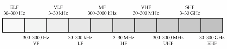
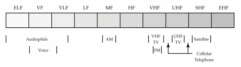
3 Electromagnetic Spectrum 3
4 c=λf Frequency and Wavelength c: speed of light λ: wavelength f: frequency Example: AM radio with frequency 1710 khz What s the wavelength? Ans: 175m What s the period? Ans: 584 ns 4
5 db Decibels 10 log 10 (x) Power in decibels db Y db=10 log 10 (x Watt) Power ratio in decibels db Power P1, P in Watt 10 log 10 (P1/P) Example: Input power 100W and output power 1W What s the power ratio in decibel? Ans: 0dB 5
6 dbm dbm Reference power is 1 mw 10 log 10 (Watts/10^-3) Example: 0 db= 30dBm=1 Watt Summary P (dbw) = 10 log (P/1 Watt) P (dbm) = 10 log (P/1 mwatt) 6
7 Gain and Attenuation in db or dbm Gain/attenuation in db 10 log 10 (output power/input power) Gain(dB)=Pout(dB)-Pin(dB) Gain: Pout > Pin Attenuation Pout<Pin Gain/attenuation in dbm X(dBm)+Y(dB) =??(db)=??(dbm) X(dBm)-Y(dB) =??(db)=??(dbm) Example: Input power is dbm, system gain is 5dB What s the output power? Ans: 7dBm Notice: is it db or dbm? 7
8 Wireless communication system Antenna gain Transmitter antenna Receiver antenna Wireless channel attenuation P tx G ant,tx G channel G ant,rx P rx Questions: how do you represent the relationships between P tx and P rx? in db in Watt 8
9 S/N Signal-to to-noise ratio SNR= signal power(watt)/noise power(watt) Signal-to-Noise power ratio Relate to the performance of communications systems Bit-error probability Shannon capacity SNR in db S/N(dB)= 10 log 10 (S/N power ratio) 10 log 10 (signal power(watt)/noise power(watt)) 9
10 Noise, Interference, SNR SNR (signal power)/(noise power) Noise: thermal noise SIR Signal-to-Interference Sometimes known as C/I (carrier-to-interference ratio) (signal power)/(interference power) Interference: signals from other simultaneous communications SINR Signal-to-Interference-Plus-Noise ratio (signal power)/(interference power+noise power) 10
11 Bandwidth B=f upper -f lower Carrier frequency: fc Example: GHz ISM band (channel 1) f upper =434MHz f lower =41MHz fc=433mhz B=MHz B frequency f lower fc f upper 11
12 Shannon Capacity Theoretical (upper) bound of communication systems C=B*log (1+S/N) C: capacity (bits/s) B: bandwidth (Hz) S/N: linear Signal-to-Noise ratio How to evaluate the performance of a communication scheme? How close to Shannon bound? Spectral efficiency bit/s/hz 1
13 Concepts Related to Channel Capacity Data rate rate at which data can be communicated (bps) Bandwidth the bandwidth of the transmitted signal as constrained by the transmitter and the nature of the transmission medium (Hertz) Noise average level of noise over the communications path Error rate - rate at which errors occur Error transmit 1 and receive 0 transmit 0 and receive 1 13
14 Shannon Capacity Formula Equation: C = B log + ( 1 SNR) Represents theoretical maximum that can be achieved (in AWGN channel) In practice, only much lower rates achieved Formula assumes white noise (thermal noise) Impulse noise is not accounted for Attenuation distortion or delay distortion not accounted for 14
15 Nyquist Bandwidth For binary signals (two voltage levels) C = B With multilevel signaling C = B log M M = number of discrete signal or voltage levels 15
16 Example of Nyquist and Shannon Formulations Spectrum of a channel between 3 MHz and 4 MHz ; SNR db = 4 db What s the SNR value? Using Shannon s formula What s the maximum capacity? 16
17 Example of Nyquist and Shannon Formulations Spectrum of a channel between 3 MHz and 4 MHz ; SNR db = 4 db B = SNR SNR 4 MHz 3 MHz db = 4 db = 10log 51 Using Shannon s formula = = 1MHz 10 ( SNR) C = 10 6 log ( ) = 8Mbps 17
18 Example of Nyquist and Shannon Formulations How many signaling levels are required in modulation? 18
19 Example of Nyquist and Shannon Formulations How many signaling levels are required? C M = = B 6 log = 16 log = M M ( 6 10 ) log M 19
20 Radio propagation model
21 Physics: wave propagation Reflection - occurs when signal encounters a surface that is large relative to the wavelength of the signal Diffraction - occurs at the edge of an impenetrable body that is large compared to wavelength of radio wave Scattering occurs when incoming signal hits an object whose size in the order of the wavelength of the signal or less 1
22 Rf generally propagate according to 4 mechanisms Reflection at large obstacles: plane waves are incident on a surface with dimensions that are very large relative compared to the wavelength. Scattering at small obstacles: occurs when the plane waves are incident upon an object whose dimensions are on the order of a wavelength or less and causes energy to be redirected in many directions. Diffraction at edges: occurs according to Huygen s principle when there is an obstruction between the transmitter and receiver antennas, and secondary waves are generated behind the obstructing body. As the frequency gets higher, the rf wave will diffract less and start to behave like light. Penetration: In addition to diffraction, penetration of objects will allow rf reception when there is an obstruction(s) between the transmitter and receiver. diffraction reflection scattering penetration
23 Wireless Channel Path loss Shadowing Delay spread Co-channel interference Multipath Propagation Path loss and shadowing Self interference Multipath [Rayleigh] fading Delay Spread: Intersymbol interference (I Doppler Shift [due to motion] Noise (SNR) Other users Co-channel interference (CCI) Adjacent-channel interference (ACI) Time & Frequency synchronization 3
24 The Effects of Multipath Propagation Multiple copies of a signal may arrive at different phases If phases add destructively, the signal level relative to noise declines, making detection more difficult Intersymbol interference (ISI) One or more delayed copies of a pulse may arrive at the same time as the primary pulse for a subsequent bit 4
25 Signal Propagation Ranges Transmission range communication possible low error rate Detection range detection of the signal possible, but communication may not be possible due to high error rate Interference range signal may not be detected signal adds to the background noise sender transmission detection interference Distance from transmitter 5
26 Radio Propagation Models Three components Path-loss (long-term average) Radio signal attenuation due to transmission over a certain distance Depend on the distance Shadowing (large time-scale variation) Signal attenuation due to penetration of buildings and walls. Log-normal distribution Fading (small time-scale variation) Due to multi-path transmission (reflection creates multiple radio paths) Rayleigh distribution, Ricean distribution 6
27 Radio Propagation Models Signal power at receiver Path-loss g(d) Log-normal shadowing Rayleigh fading α x P R x = α g( d) P G T T G R 7
28 Path-loss Denoted as g(d) Path-loss P = g( d) P G Represent average values (local mean power of area within several meters) g( d In general received signal strength is proportional to d -n n: path-loss exponent k: constant n= ~ 8 in typical propagation scenarios n=4 is usually assumed in cellular system study Example: Free-space model P r = (P t G t G r λ )/(16π d )= (P t G t G r )(λ/4πd) Proportional to d - (i.e. n=) R T ) T G R d n 8
29 Some more path-loss models Smooth transition model Two-ray-ground model Okumura-Hatamodel More models in telecom standard evaluation E.g. 3GPP, IMT-000, 80.16, EU WINNER project Common ground to evaluate proposed schemes Reflect the radio operation conditions (frequency, terminal speed, urban/rural) 9
30 Smooth transition model Improvement over simple distance-power relationship ) n g d = d d -n Two-stage transition model ( d ) + ( 1 1 n Typically, n is smaller value in near-field and is a greater value in far-field n Empirical measurement g d = d 1 ( ) 0 d g( d) = d 1 ( d / b ) b n n b b d model location n1 n b(m) Harley Melbourne 1.5 to.5 3 to Green London 1.7 to.1 to Pickhlotz Orlando
31 Two-ray model radio paths LOS(line-of-sight) NLOS(non-line-of-sight) Proof? Reflection from the ground Sum the power of these EM waves g( d) = ( h h ) t d r 4 LOS h t NLOS h r d 31
32 Okumura-Hata model Model + measurement fit For macro-cellular network Good fit for distance greater than 1km MHz Practical use in cellular network planning Extend by COST (European Cooperative for Scientific and Technical Research) COST-31 model: suitable for urban microcells ( MHz) 3
33 Hata Model for Mean Path Loss Early studies by Hata [IEEE Trans. On Vehicular Technology, Vol. 9 pp45-51, 1980] yielded empirical path loss models for urban, suburban, and rural (macrocellular) areas that are accurate to with 1dB for distances ranging from 1 to 0 km. The parameters used in the Hata equations and their range of validity are: fc = carrier frequency (MHz) 150 < fc < 1,500 MHz d = distance between base station and mobile (km) 1 < d < 0 km hb and hm = base and mobile antenna heights (m) 30 < hb < 00m, 1 < hm < 10m 33
34 Hata Model for Mean Path Loss Hata s equations for path loss are classified into three models Typical Urban L ( db) = log f + ( log h )log d 13.8 log h where f urban Large cities α( h Small and medium size cities α( h m m Typical Suburban (note adding a negative number to the loss means a higher signal level) fc Lsuburban( db) = Lurban log( ) Rural α( h ) = 8.9[log(1.54h = 3.[log(11.75h ) = [1.1log( f L m is in MHz, h ) = correction factor for mobile antenna heights and is given by b rural and c h m )] )] ) 0.7] h is in m, d m m m c is in km f c f c [1.56 log( f 00 MHz 400 MHz c ) 0.8] ( db) = Lurban 4.78[log( fc)] log( fc) b b α( h m db ) 34
35 COST-31 path-loss model Extend Hata model for PCS radio model in urban area L( db) = log f 13.8 log hb a( hm ) + [ log hb ]log d + CM where α( hm ) = correction factor for mobile antenna heights given in Hata model f is in MHz, hb and hm is in m, d is in km Large cities CM = 0 db Small and medium size cities C = 3dB M 35
36 Shadowing Shadowing is also known as shadow fading Received signal strength fluctuation around the mean value Due to radio signal blocking by buildings (outdoor), walls (indoor), and other obstacles. Large time-scale variation Signal fluctuation is much slower than multipath fading 36
37 Log-normal distribution If logarithm of a variable x follows normal distribution, then x follows log-normal ditribution Log-normal distribution for shadowing model P.d.f f 1 (ln x ( x) = exp( σ πσx μ ) ) 37
38 Log-normal shadowing Path loss component indicates the expected signal attenuation at distance d The actual signal attenuation at d depends on the environment. This is modeled with shadowing effect. Statistical model for shadowing Received mean power of the radio signal fluctuates about the area-mean power with a log-normal distribution Log-normal distribution (in Watt) Normal distribution if measured in db x is a zero-mean Gaussian variable with standard deviation σ db. Typically, σ = 6~10 db P R x = α g( d) P G T T G R P R ( db) = P R ( db) + S S ~ N(0, σ ), σ = 4 ~ 10dB 38
39 Three-Part Propagation Model: Path Loss, Slow Shadow Fading, and Fast Rayleigh Fading Shadow Fading Rayleigh fading about average 10-5 Received Signal Strength [milliwatts] Average x 10 Relative Signal Level Average received signal strength Average Average 10 Average 100 Separation Distance [meters] 10-9 Average Average Path Loss Separation Distance [kilometers] The effects of path loss, shadow fading and fading are essentially independent and multiplicative 39
40 Transmission range Ideal case With shadowing It might vary with time 40
41 Multi-path fading Multiple radio propagation paths Might include LOS path or not Multiple copies of received signals Different time delay Different phase Different amplitude More severe in urban area or indoor Characterized by Rayleigh or Ricean distribution Delay spread profile 41
42 Effects of multi-path signals Multiple copies of a signal may arrive at different phases If phases add destructively, the signal level relative to noise declines, making detection more difficult Intersymbol interference (ISI) One or more delayed copies of a pulse may arrive at the same time as the primary pulse for a subsequent bit 4
43 Multipath Propagation Signals can take many different paths between sender and receiver due to reflection, scattering, diffraction At receiver antenna: vector sum signal at sender signal at receiver Positive effects of multipath: Enables communication even when transmitter and receiver are not in LOS conditions - allows radio waves effectively to go through obstacles by getting around them, thereby increasing the radio coverage area By proper processing of the multipath signals, with smart or adaptive antennas, you can substantially increase the usable received power With multiple antennas you capture energy that would otherwise be absorbed by the atmosphere and you can compensate for fades --- since it is highly unlikely that a signal will experience severe fading at more than one antenna 43
44 Negative effects of small-scale scale fading Time dispersion or delay spread: signal is dispersed over time due signals coming over different paths of different lengths. This causes interference with neighboring symbols, this is referred to as Inter Symbol Interference (ISI) The signal reaches a receiver directly and phase shifted (due to reflections) as a distorted signal depending on the phases of the different paths; this is referred to as Rayleigh fading, due to the distribution of the fades. Rayleigh fading creates fast fluctuations of the received signal (fast fading). Random frequency modulation due to Doppler frequency shifts on the different paths. Doppler shift is caused by the relative velocity of the receiver to the transmitter, leads to a frequency variation of the received signal. 44
45 Delay spread and coherent bandwidth Reminder duality property of signals in time-domain and frequency domain Power delay profile signal strength Time domain multi-path delay spread Frequency domain time coherent bandwidth B c Highly correlated signals among these frequency components 45
46 Power Delay Profile In order to compare different multi-path channels, the time dispersive power profile is treated as an (nonnormalized) pdf from which the following are computed Mean delay : τ = k α k k α τ k k, Mean square delay : τ = k α k k α τ k k The RMS Delay Spread : σ τ = τ ( τ ) (.5) Typical values of rms delay spread are on the order of microseconds in outdoor mobile radio channels [GSM specifies a maximum delay less than 0μs] and on the order of nanoseconds in indoor radio channels 46
47 Example (Power delay profile) 0 db -10 db P r (τ) 4.38 µs 1.37 µs -0 db -30 db (µs) τ Avg delay _ (1)(5) + (0.1)(1) + (0.1)() + (0.01)(0) τ = = 4. 38μs [ ] _ (1)(5) + (0.1)(1) + (0.1)() + (0.01)(0) τ = = 1.07μs [ ] σ τ = 1.07 (4.38) = 1. 37μs Delay spread 47

 P G ( α")
48 Rayleigh fading Amplitude follows Rayleigh distribution P How to derive it? Add several scaled and delayed versions of a sinusoid function R p R x = α g( d) P G ( α ) T α = e σ T α G R / σ 48
49 Ricean Fading Some types of scattering environments have a LOS component (in addition to the scattered components) ---typically in microcellular and satellite systems. This dominant path may significantly decrease the depth of fading, and in this case g I (t) and g Q (t) are Gaussian random processes with non-zero means m I (t) and m Q (t). We can assume that these processes are uncorrelated and the random variables g I (t) and g Q (t) have the same variance, σ, then the received complex envelope has the Ricean distribution x pr ( x) = e σ where s = m and the zero order Bessel function of I 0 ( x) = 1 π ( x + s I ) π cos x θ e 0 xs σ I0( ) σ ( t) + m ( t) dθ Q x 0 the first kind The Rice factor, K, is defined as the ratio of the specular (LoS) power to the scattered power ( specular) power in the dominant path K = = power in the scattered paths I 0 ( x) s σ is defined by 49
50 Ricean Fading When K=0, the channel exhibits Rayleigh fading and for K there is no fading and the channel is Gaussian. Most channels can be characterized as either Rayleigh, Rician, or Gaussian --- with Rician being the most general case ---the Rician pdf is shown below. 50
51 Rician Fading Profiles for a Mobile at 90 Km/Hr Amplitude (db) K = 0, 4, 8, 16, and 3 (a) (b) (c) (d) (e) ~Rayleigh time ~Gaussian 51
52 Doppler Shift The motion of the mobile introduces a Doppler (or frequency) shift into the incident plane wave and is given by f D = f m cosθ n Hz where f m = v/λ is the maximum Doppler shift that occurs when θ = 0. Waves arriving from the direction of motion will experience a positive shift, while those arriving from the opposite direction will experience a negative shift. θ v 5
53 Doppler Shift Spectrum For isotropic -dimensional scattering and isotropic scattering The power spectrum of the received signal is limited in range to f m about the carrier frequency) S(ƒ) S( f ) A = 4 π f m 1 1 f f m f c f f c f m ƒ c f m ƒ c ƒ c + f m frequency 53
54 Effect of Doppler Shift Time-frequency duality The Doppler effect produces frequency dispersion (an increase in the bandwidth occupancy) This is equivalent to time-selective fading in the received signal Coherence Time Doppler frequency shift (frequency domain) could be represented as coherence time (time domain) Tc Represent the time duration that channel is stable If symbol time is smaller than Tc, it is called slow fading. Otherwise it is fast fading. 54
55 Mitigate Doppler shift If the baseband signal bandwidth is much greater than the maximum Doppler shift, then the effects of Doppler spread are negligible at the receiver. To minimize the effect of Doppler, we should use as wide a baseband signal as feasible [e.g. spread spectrum] 55
56 Types of fading Summary: Fading (based on multipath time delay spread) Signal is correlated or not (time) Channel frequency response depends on frequency or not (frequency) 1. Flat Fading BW of signal < BW of channel Delay spread < Symbol period. Frequency Selective (non-flat) Fading BW of signal > BW of channel Delay spread > symbol period Summary: Fading (based on Doppler spread) Channel varies faster or slower than signal symbol (time) High or low frequency dispersion (frequency) 1. Slow Fading Low Doppler spread Coherence time > Symbol period Channel variations slower than baseband signal variations. Fast Fading High Doppler spread Coherence time < symbol period (time selective fading) Channel variations faster than baseband signal variations 56
57 Small scale fading Multi path time delay Flat fading B S B C B S Frequency selective fading B C fading Doppler spread Fast fading Slow fading T S T C T S T C 57
58 Summary of radio propagation and mitigations Shadowing Problem: received signal strength Mitigation: increase transmit power Reduce cell size Fast fading Problem: error rate (BER, FER, PER) Mitigation: Interleaving Error correction coding Frequency hopping Diversity techniques Delay spread Problem: ISI and error rates Mitigation: Equalization Spread spectrum OFDM Directional antenna 58
59 How to create propagation models? General ray-tracing method (simulation) 3D building database with topography Multiple ray-tracing with propagation effects (reflection, diffraction, LOS path, scattering, etc) Might consider building material (steel, concrete, brick,etc) Empirical method On-site measurement Curve-fitting Could be combined with ray-tracing method 59
60 Review question? In which case do you expect better propagation condition? Indoor or outdoor With LOS or NLOS Fixed or mobile user 60
61 What s s your propagation environment? Surroundings Indoor, outdoor, street, open-area LOS or NLOS Line-of-sight or not? Design choices? Coding, modulation Re-transmission (ARQ-Automatic Repeat-reQuest) QoS requirement (at different layers) Data rate requirement BER (bit-error-rate) FER (frame-error-rate) Depend on BER and frame size 61
62 Diversity technique Diversity techniques improve the system performance with multi-path signals Not just avoid multi-path condition, but take advantage of it Applicable in several aspects Time diversity Frequency diversity Spatial diversity Examples Linear combining Sum of all received signals at each branch Maximal-ratio combining Weighted sum (weight is proportional to the received signal strength at each branch) 6
63 Types of Diversity used for Combating Multipath Fading Type Space Time Frequency Technique applied Receiving antennas sufficiently separated for independent fading. Send sequential time samples [interleaving]. Equalization Transmit using different carrier frequencies separated by frequencies greater than the coherence bandwidth for independent fading; or by wideband spread spectrum transmission. Polarization Transmit using two orthogonal polarizations for independent fading 63
64 Review: types of fading What are the definitions of the following terms? Fast fading Slow fading Flat fading Selective fading Rayleigh fading Rician fading 64
65 Cross-Layer Design and Optimization
66 Radio Propagation Model Understand wireless PHY property is the first step to conduct cross-layer design and engineering Channel property affects communication system performance significantly Cross-layer design could be optimized according to the radio propagation model Indoor V.S. outdoor LOS V.S. NLOS Speed (static, low-speed, high-speed) Doppler shift Example: wireless communications over high-speed trains is challenging 66
67 Abstract Model Abstract model is helpful in cross-layer design Sophisticated model could be too complex Difficult to provide design insight Radio propagation model channel state varies Markov Chain model Simple example: -state Markov chain Good state and bad state Gilbert/Elliot model 67
Antennas & Propagation. CS 6710 Spring 2010 Rajmohan Rajaraman
 Antennas & Propagation CS 6710 Spring 2010 Rajmohan Rajaraman Introduction An antenna is an electrical conductor or system of conductors o Transmission - radiates electromagnetic energy into space o Reception
EE4367 Telecom. Switching & Transmission. Prof. Murat Torlak
 Path Loss Radio Wave Propagation The wireless radio channel puts fundamental limitations to the performance of wireless communications systems Radio channels are extremely random, and are not easily analyzed
CDMA Performance under Fading Channel
 CDMA Performance under Fading Channel Ashwini Dyahadray 05307901 Under the guidance of: Prof Girish P Saraph Department of Electrical Engineering Overview Wireless channel fading characteristics Large
I. Wireless Channel Modeling
 I. Wireless Channel Modeling April 29, 2008 Qinghai Yang School of Telecom. Engineering qhyang@xidian.edu.cn Qinghai Yang Wireless Communication Series 1 Contents Free space signal propagation Pass-Loss
T = 1 f. Phase. Measure of relative position in time within a single period of a signal For a periodic signal f(t), phase is fractional part t p
, phase is fractional part t p") Data Transmission Concepts and terminology Transmission terminology Transmission from transmitter to receiver goes over some transmission medium using electromagnetic waves Guided media. Waves are guided
Data Transmission Concepts and terminology Transmission terminology Transmission from transmitter to receiver goes over some transmission medium using electromagnetic waves Guided media. Waves are guided
Digital Modulation. David Tipper. Department of Information Science and Telecommunications University of Pittsburgh. Typical Communication System
 Digital Modulation David Tipper Associate Professor Department of Information Science and Telecommunications University of Pittsburgh http://www.tele.pitt.edu/tipper.html Typical Communication System Source
1 Lecture Notes 1 Interference Limited System, Cellular. Systems Introduction, Power and Path Loss
 ECE 5325/6325: Wireless Communication Systems Lecture Notes, Spring 2015 1 Lecture Notes 1 Interference Limited System, Cellular Systems Introduction, Power and Path Loss Reading: Mol 1, 2, 3.3, Patwari
is the power reference: Specifically, power in db is represented by the following equation, where P0 P db = 10 log 10
 RF Basics - Part 1 This is the first article in the multi-part series on RF Basics. We start the series by reviewing some basic RF concepts: Decibels (db), Antenna Gain, Free-space RF Propagation, RF Attenuation,
communication over wireless link handling mobile user who changes point of attachment to network
 Wireless Networks Background: # wireless (mobile) phone subscribers now exceeds # wired phone subscribers! computer nets: laptops, palmtops, PDAs, Internet-enabled phone promise anytime untethered Internet
Omni Antenna vs. Directional Antenna
 Omni Antenna vs. Directional Antenna Document ID: 82068 Contents Introduction Prerequisites Requirements Components Used Conventions Basic Definitions and Antenna Concepts Indoor Effects Omni Antenna Pros
PART 5D TECHNICAL AND OPERATING CHARACTERISTICS OF MOBILE-SATELLITE SERVICES RECOMMENDATION ITU-R M.1188
 Rec. ITU-R M.1188 1 PART 5D TECHNICAL AND OPERATING CHARACTERISTICS OF MOBILE-SATELLITE SERVICES Rec. ITU-R M.1188 RECOMMENDATION ITU-R M.1188 IMPACT OF PROPAGATION ON THE DESIGN OF NON-GSO MOBILE-SATELLITE
T-79.7001 Postgraduate Course in Theoretical Computer Science T-79.5401 Special Course in Mobility Management: Ad hoc networks (2-10 cr) P V
 P V") T-79.7001 Postgraduate Course in Theoretical Computer Science T-79.5401 Special Course in Mobility Management: Ad hoc networks (2-10 cr) P V professor Hannu H. Kari Laboratory for Theoretical Computer
T-79.7001 Postgraduate Course in Theoretical Computer Science T-79.5401 Special Course in Mobility Management: Ad hoc networks (2-10 cr) P V professor Hannu H. Kari Laboratory for Theoretical Computer
ISI Mitigation in Image Data for Wireless Wideband Communications Receivers using Adjustment of Estimated Flat Fading Errors
 International Journal of Engineering and Management Research, Volume-3, Issue-3, June 2013 ISSN No.: 2250-0758 Pages: 24-29 www.ijemr.net ISI Mitigation in Image Data for Wireless Wideband Communications
Outdoor Propagation Prediction in Wireless Local Area Network (WLAN)
") Outdoor Propagation Prediction in Wireless Local Area Network (WLAN) Akpado K.A 1, Oguejiofor O.S 1, Abe Adewale 2, Femijemilohun O.J 2 1 Department of Electronic and Computer Engineering, Nnamdi Azikiwe
Outdoor Propagation Prediction in Wireless Local Area Network (WLAN) Akpado K.A 1, Oguejiofor O.S 1, Abe Adewale 2, Femijemilohun O.J 2 1 Department of Electronic and Computer Engineering, Nnamdi Azikiwe
System Design in Wireless Communication. Ali Khawaja
 System Design in Wireless Communication Ali Khawaja University of Texas at Dallas December 6, 1999 1 Abstract This paper deals with the micro and macro aspects of a wireless system design. With the growing
Understanding Range for RF Devices
 Understanding Range for RF Devices October 2012 White Paper Understanding how environmental factors can affect range is one of the key aspects to deploying a radio frequency (RF) solution. This paper will
Department of Electrical and Computer Engineering Ben-Gurion University of the Negev. LAB 1 - Introduction to USRP
 Department of Electrical and Computer Engineering Ben-Gurion University of the Negev LAB 1 - Introduction to USRP - 1-1 Introduction In this lab you will use software reconfigurable RF hardware from National
Data Transmission. Raj Jain. Professor of CIS. The Ohio State University. Columbus, OH 43210 Jain@ACM.Org http://www.cis.ohio-state.
 Data Transmission Professor of CIS Columbus, OH 43210 Jain@ACM.Org http://www.cis.ohio-state.edu/~jain/ 2-1 Overview Time Domain and Frequency Domain Bit, Hertz Decibels Data vs Signal Attenuation, Delay
Dynamic Reconfiguration & Efficient Resource Allocation for Indoor Broadband Wireless Networks
 Dynamic Reconfiguration & Efficient Resource Allocation for Indoor Broadband Wireless Networks Tim Farnham, Brian Foxon* Home Communications Department HP Laboratories Bristol HPL-98-123 June, 1998 broadband,
GSM frequency planning
 GSM frequency planning Band : 890-915 and 935-960 MHz Channel spacing: 200 khz (but signal bandwidth = 400 khz) Absolute Radio Frequency Channel Number (ARFCN) lower band: upper band: F l (n) = 890.2 +
COMPATIBILITY STUDY FOR UMTS OPERATING WITHIN THE GSM 900 AND GSM 1800 FREQUENCY BANDS
 Electronic Communications Committee (ECC) within the European Conference of Postal and Telecommunications Administrations (CEPT) COMPATIBILITY STUDY FOR UMTS OPERATING WITHIN THE GSM 900 AND GSM 1800 FREQUENCY
Pointers on using the 5GHz WiFi bands
 Pointers on using the 5GHz WiFi bands Legalities In the UK, there are two main types of radio devices that use the 5GHz frequency bands. The most common are those devices that conform to the 11a standard.
AN1200.04. Application Note: FCC Regulations for ISM Band Devices: 902-928 MHz. FCC Regulations for ISM Band Devices: 902-928 MHz
 AN1200.04 Application Note: FCC Regulations for ISM Band Devices: Copyright Semtech 2006 1 of 15 www.semtech.com 1 Table of Contents 1 Table of Contents...2 1.1 Index of Figures...2 1.2 Index of Tables...2
A Performance Study of Wireless Broadband Access (WiMAX)
") A Performance Study of Wireless Broadband Access (WiMAX) Maan A. S. Al-Adwany Department of Computer & Information Engineering, College of Electronics Engineering University of Mosul Mosul, Iraq maanaladwany@yahoo.com
A Performance Study of Wireless Broadband Access (WiMAX) Maan A. S. Al-Adwany Department of Computer & Information Engineering, College of Electronics Engineering University of Mosul Mosul, Iraq maanaladwany@yahoo.com
Radio Physics for Wireless Devices and Networking. The Radio Physics of WiFi. By Ron Vigneri
 Radio Physics for Wireless Devices and Networking By Ron Vigneri The Radio Physics of WiFi The standard for wireless LANs (WLANs) was completed in 1997 with the release of the IEEE 802.11 specification
INTRODUCTION TO COMMUNICATION SYSTEMS AND TRANSMISSION MEDIA
 COMM.ENG INTRODUCTION TO COMMUNICATION SYSTEMS AND TRANSMISSION MEDIA 9/6/2014 LECTURES 1 Objectives To give a background on Communication system components and channels (media) A distinction between analogue
Data Transmission. Data Communications Model. CSE 3461 / 5461: Computer Networking & Internet Technologies. Presentation B
 CSE 3461 / 5461: Computer Networking & Internet Technologies Data Transmission Presentation B Kannan Srinivasan 08/30/2012 Data Communications Model Figure 1.2 Studying Assignment: 3.1-3.4, 4.1 Presentation
A SIMULATION STUDY ON SPACE-TIME EQUALIZATION FOR MOBILE BROADBAND COMMUNICATION IN AN INDUSTRIAL INDOOR ENVIRONMENT
 A SIMULATION STUDY ON SPACE-TIME EQUALIZATION FOR MOBILE BROADBAND COMMUNICATION IN AN INDUSTRIAL INDOOR ENVIRONMENT U. Trautwein, G. Sommerkorn, R. S. Thomä FG EMT, Ilmenau University of Technology P.O.B.
DVB-SH. Radio Network Planning Tool. (Release 4.2)
") DVB-SH Radio Network Planning Tool (Release 4.2) by AWE Communications GmbH. All rights reserved 1 1 Introduction 1.1 Overview Digital Video Broadcasting Satellite to Handheld (DVB-SH) aims to provide
DVB-SH Radio Network Planning Tool (Release 4.2) by AWE Communications GmbH. All rights reserved 1 1 Introduction 1.1 Overview Digital Video Broadcasting Satellite to Handheld (DVB-SH) aims to provide
Antenna Properties and their impact on Wireless System Performance. Dr. Steven R. Best. Cushcraft Corporation 48 Perimeter Road Manchester, NH 03013
 Antenna Properties and their impact on Wireless System Performance Dr. Steven R. Best Cushcraft Corporation 48 Perimeter Road Manchester, NH 03013 Phone (603) 627-7877 FAX: (603) 627-1764 Email: sbest@cushcraft.com
MODULATION Systems (part 1)
") Technologies and Services on Digital Broadcasting (8) MODULATION Systems (part ) "Technologies and Services of Digital Broadcasting" (in Japanese, ISBN4-339-62-2) is published by CORONA publishing co.,
Technologies and Services on Digital Broadcasting (8) MODULATION Systems (part ) "Technologies and Services of Digital Broadcasting" (in Japanese, ISBN4-339-62-2) is published by CORONA publishing co.,
Antenna Deployment Technical Brief
 ProCurve Networking Antenna Deployment Technical Brief Introduction... 2 Antenna types... 2 Omni directional antennas... 2 Directional antennas... 2 Diversity antennas... 3 High gain directional antennas...
Maximizing Throughput and Coverage for Wi Fi and Cellular
 Maximizing Throughput and Coverage for Wi Fi and Cellular A White Paper Prepared by Sebastian Rowson, Ph.D. Chief Scientist, Ethertronics, Inc. www.ethertronics.com March 2012 Introduction Ask consumers
LTE PHY Fundamentals Roger Piqueras Jover
 LTE PHY Fundamentals Roger Piqueras Jover DL Physical Channels - DL-SCH: The DownLink Shared CHannel is a channel used to transport down-link user data or Radio Resource Control (RRC) messages, as well
SIMULATION OF RADIOWAVE PROPAGATION USING PROPAGATION MODELS
 SIMULATION OF RADIOWAVE PROPAGATION USING PROPAGATION MODELS Yelena Chaiko Transport Communications and Information Systems professor group Riga Technical University Institute of Railway Transport Indrika,
DT3: RF On/Off Remote Control Technology. Rodney Singleton Joe Larsen Luis Garcia Rafael Ocampo Mike Moulton Eric Hatch
 DT3: RF On/Off Remote Control Technology Rodney Singleton Joe Larsen Luis Garcia Rafael Ocampo Mike Moulton Eric Hatch Agenda Radio Frequency Overview Frequency Selection Signals Methods Modulation Methods
COMPATIBILITY AND SHARING ANALYSIS BETWEEN DVB T AND RADIO MICROPHONES IN BANDS IV AND V
 European Radiocommunications Committee (ERC) within the European Conference of Postal and Telecommunications Administrations (CEPT) COMPATIBILITY AND SHARING ANALYSIS BETWEEN DVB T AND RADIO MICROPHONES
White Paper: Microcells A Solution to the Data Traffic Growth in 3G Networks?
 White Paper: Microcells A Solution to the Data Traffic Growth in 3G Networks? By Peter Gould, Consulting Services Director, Multiple Access Communications Limited www.macltd.com May 2010 Microcells were
Inter-Cell Interference Coordination (ICIC) Technology
 Technology") Inter-Cell Interference Coordination (ICIC) Technology Dai Kimura Hiroyuki Seki Long Term Evolution (LTE) is a promising standard for next-generation cellular systems targeted to have a peak downlink bit
Inter-Cell Interference Coordination (ICIC) Technology Dai Kimura Hiroyuki Seki Long Term Evolution (LTE) is a promising standard for next-generation cellular systems targeted to have a peak downlink bit
Attenuation (amplitude of the wave loses strength thereby the signal power) Refraction Reflection Shadowing Scattering Diffraction
 Refraction Reflection Shadowing Scattering Diffraction") Wireless Physical Layer Q1. Is it possible to transmit a digital signal, e.g., coded as square wave as used inside a computer, using radio transmission without any loss? Why? It is not possible to transmit
Wireless Physical Layer Q1. Is it possible to transmit a digital signal, e.g., coded as square wave as used inside a computer, using radio transmission without any loss? Why? It is not possible to transmit
An Algorithm for Automatic Base Station Placement in Cellular Network Deployment
 An Algorithm for Automatic Base Station Placement in Cellular Network Deployment István Törős and Péter Fazekas High Speed Networks Laboratory Dept. of Telecommunications, Budapest University of Technology
Avaya WLAN 9100 External Antennas for use with the WAO-9122 Access Point
 Avaya WLAN 9100 External Antennas for use with the WAO-9122 Access Point Overview To optimize the overall performance of a WLAN in an outdoor deployment it is important to understand how to maximize coverage
Mobile Communications Chapter 2: Wireless Transmission
 Mobile Communications Chapter 2: Wireless Transmission Frequencies Signals Antennas Signal propagation Multiplexing Spread spectrum Modulation Cellular systems Prof. Dr.-Ing. Jochen Schiller, http://www.jochenschiller.de/
TCOM 370 NOTES 99-4 BANDWIDTH, FREQUENCY RESPONSE, AND CAPACITY OF COMMUNICATION LINKS
 TCOM 370 NOTES 99-4 BANDWIDTH, FREQUENCY RESPONSE, AND CAPACITY OF COMMUNICATION LINKS 1. Bandwidth: The bandwidth of a communication link, or in general any system, was loosely defined as the width of
White Paper FADING BASICS. Narrow Band, Wide Band, and Spatial Channels White Paper 101. Rev. X mm/08
 White Paper FADING BASICS Narrow Band, Wide Band, and Spatial Channels White Paper 101 Rev. X mm/08 SPIRENT 1325 Borregas Avenue Sunnyvale, CA 94089 USA Email: Web: sales@spirent.com http://www.spirent.com
Frequency Hopping Spread Spectrum (FHSS) vs. Direct Sequence Spread Spectrum (DSSS) in Broadband Wireless Access (BWA) and Wireless LAN (WLAN)
 vs. Direct Sequence Spread Spectrum (DSSS) in Broadband Wireless Access (BWA) and Wireless LAN (WLAN)") FHSS vs. DSSS page 1 of 16 Frequency Hopping Spread Spectrum (FHSS) vs. Direct Sequence Spread Spectrum (DSSS) in Broadband Wireless Access (BWA) and Wireless LAN (WLAN) by Sorin M. SCHWARTZ Scope In 1997
FHSS vs. DSSS page 1 of 16 Frequency Hopping Spread Spectrum (FHSS) vs. Direct Sequence Spread Spectrum (DSSS) in Broadband Wireless Access (BWA) and Wireless LAN (WLAN) by Sorin M. SCHWARTZ Scope In 1997
NON-LINE OF SIGHT: TECHNOLOGY & IMPLEMENTATION
 SOLECTEK WHITE PAPER NON-LINE OF SIGHT: TECHNOLOGY & IMPLEMENTATION Introduction To many industry insiders, the promise of broadband wireless access (BWA) is clear. Delivery of last mile, enterprise infrastructure
Propagation Channel Emulator ECP_V3
 Navigation simulators Propagation Channel Emulator ECP_V3 1 Product Description The ECP (Propagation Channel Emulator V3) synthesizes the principal phenomena of propagation occurring on RF signal links
Small-Cell Wireless Backhauling
 Small-Cell Wireless Backhauling A Non-Line-of-Sight Approach for Point-to-Point Microwave Links M. Coldrey*, H. Koorapaty**, J.-E. Berg***, Z. Ghebretensaé***, J. Hansryd****, A. Derneryd*, S. Falahati***
Implementation of Digital Signal Processing: Some Background on GFSK Modulation
 Implementation of Digital Signal Processing: Some Background on GFSK Modulation Sabih H. Gerez University of Twente, Department of Electrical Engineering s.h.gerez@utwente.nl Version 4 (February 7, 2013)
EECC694 - Shaaban. Transmission Channel
 The Physical Layer: Data Transmission Basics Encode data as energy at the data (information) source and transmit the encoded energy using transmitter hardware: Possible Energy Forms: Electrical, light,
The Effect of Network Cabling on Bit Error Rate Performance. By Paul Kish NORDX/CDT
 The Effect of Network Cabling on Bit Error Rate Performance By Paul Kish NORDX/CDT Table of Contents Introduction... 2 Probability of Causing Errors... 3 Noise Sources Contributing to Errors... 4 Bit Error
1 Multi-channel frequency division multiplex frequency modulation (FDM-FM) emissions
 emissions") Rec. ITU-R SM.853-1 1 RECOMMENDATION ITU-R SM.853-1 NECESSARY BANDWIDTH (Question ITU-R 77/1) Rec. ITU-R SM.853-1 (1992-1997) The ITU Radiocommunication Assembly, considering a) that the concept of necessary
Rec. ITU-R SM.853-1 1 RECOMMENDATION ITU-R SM.853-1 NECESSARY BANDWIDTH (Question ITU-R 77/1) Rec. ITU-R SM.853-1 (1992-1997) The ITU Radiocommunication Assembly, considering a) that the concept of necessary
Scheduling and capacity estimation in LTE. Olav Østerbø, Telenor CD (Corporate Development) ITC-23, September 6-8, 2011, San Francisco
 ITC-23, September 6-8, 2011, San Francisco") Scheduling and capacity estimation in LTE Olav Østerbø, Telenor CD (Corporate Development) Agenda Introduction Obtainable bitrate as function of SINR Radio channel propagation model Radio signal fading
Scheduling and capacity estimation in LTE Olav Østerbø, Telenor CD (Corporate Development) Agenda Introduction Obtainable bitrate as function of SINR Radio channel propagation model Radio signal fading
Radar Systems Engineering Lecture 6 Detection of Signals in Noise
 Radar Systems Engineering Lecture 6 Detection of Signals in Noise Dr. Robert M. O Donnell Guest Lecturer Radar Systems Course 1 Detection 1/1/010 Block Diagram of Radar System Target Radar Cross Section
Sampling Theorem Notes. Recall: That a time sampled signal is like taking a snap shot or picture of signal periodically.
 Sampling Theorem We will show that a band limited signal can be reconstructed exactly from its discrete time samples. Recall: That a time sampled signal is like taking a snap shot or picture of signal
RF Measurements Using a Modular Digitizer
 RF Measurements Using a Modular Digitizer Modern modular digitizers, like the Spectrum M4i series PCIe digitizers, offer greater bandwidth and higher resolution at any given bandwidth than ever before.
OUTLOOK. Considerations in the Choice of Suitable Spectrum for Mobile Communications. Visions and research directions for the Wireless World
 OUTLOOK Visions and research directions for the Wireless World November 2008, No 2 Considerations in the Choice of Suitable Spectrum for Mobile Communications WG8 White Paper Considerations in the Choice
National Technical University of Athens School of Electrical and Computer Engineering
 the simulation and analysis of OFDMA subcarrier allocation techniques in multicellular environments. the performance evaluation of simple algorithms compared to a more sophisticated and computationally
How performance metrics depend on the traffic demand in large cellular networks
 How performance metrics depend on the traffic demand in large cellular networks B. B laszczyszyn (Inria/ENS) and M. K. Karray (Orange) Based on joint works [1, 2, 3] with M. Jovanovic (Orange) Presented
Antenna Diversity in Wireless Local Area Network Devices
 Antenna Diversity in Wireless Local Area Network Devices Frank M. Caimi, Ph.D. Kerry L. Greer Jason M. Hendler January 2002 Introduction Antenna diversity has been used in wireless communication systems
AN INTRODUCTION TO TELEMETRY PART 1: TELEMETRY BASICS
 AN INTRODUCTION TO TELEMETRY PART 1: TELEMETRY BASICS Telemetry is defined as the sensing and measuring of information at some remote location and then transmitting that information to a central or host
Whitepaper. 802.11n The Next Generation in Wireless Technology
 Whitepaper 802.11n The Next Generation in Wireless Technology Introduction Wireless technology continues to evolve and add value with its inherent characteristics. First came 802.11, then a & b, followed
Multihopping for OFDM based Wireless Networks
 Multihopping for OFDM based Wireless Networks Jeroen Theeuwes, Frank H.P. Fitzek, Carl Wijting Center for TeleInFrastruktur (CTiF), Aalborg University Neils Jernes Vej 12, 9220 Aalborg Øst, Denmark phone:
On the Traffic Capacity of Cellular Data Networks. 1 Introduction. T. Bonald 1,2, A. Proutière 1,2
 On the Traffic Capacity of Cellular Data Networks T. Bonald 1,2, A. Proutière 1,2 1 France Telecom Division R&D, 38-40 rue du Général Leclerc, 92794 Issy-les-Moulineaux, France {thomas.bonald, alexandre.proutiere}@francetelecom.com
The Application of Land Use/ Land Cover (Clutter) Data to Wireless Communication System Design
 Data to Wireless Communication System Design") Technology White Paper The Application of Land Use/ Land Cover (Clutter) Data to Wireless Communication System Design The Power of Planning 1 Harry Anderson, Ted Hicks, Jody Kirtner EDX Wireless, LLC Eugene,
Technology White Paper The Application of Land Use/ Land Cover (Clutter) Data to Wireless Communication System Design The Power of Planning 1 Harry Anderson, Ted Hicks, Jody Kirtner EDX Wireless, LLC Eugene,
Various Technics of Liquids and Solids Level Measurements. (Part 3)
") (Part 3) In part one of this series of articles, level measurement using a floating system was discusses and the instruments were recommended for each application. In the second part of these articles,
(Part 3) In part one of this series of articles, level measurement using a floating system was discusses and the instruments were recommended for each application. In the second part of these articles,
HD Radio FM Transmission System Specifications Rev. F August 24, 2011
 HD Radio FM Transmission System Specifications Rev. F August 24, 2011 SY_SSS_1026s TRADEMARKS HD Radio and the HD, HD Radio, and Arc logos are proprietary trademarks of ibiquity Digital Corporation. ibiquity,
Channel Models A Tutorial1
 Channel Models A Tutorial1 V1. February 21, 27 Please send comments/corrections/feedback to Raj Jain, jain@acm.org Please send comments to jain@acm.org 1 This work was sponsored in part by WiMAX Forum.
ABHELSINKI UNIVERSITY OF TECHNOLOGY
 Basic of Propagation Theory S-72.333 Physical Layer Methods in Wireless Communication Systems Fabio Belloni Helsinki University of Technology Signal Processing Laboratory fbelloni@wooster.hut.fi 23 November
Interpreting the Information Element C/I
 Prepared Date Rev Document no pproved File/reference 1(17) 2000-04-11 Interpreting the Information Element C/I This document primarily addresses users of TEMS Investigation. 2(17) 1 Introduction Why is
1. (Ungraded) A noiseless 2-kHz channel is sampled every 5 ms. What is the maximum data rate?
 A noiseless 2-kHz channel is sampled every 5 ms. What is the maximum data rate?") Homework 2 Solution Guidelines CSC 401, Fall, 2011 1. (Ungraded) A noiseless 2-kHz channel is sampled every 5 ms. What is the maximum data rate? 1. In this problem, the channel being sampled gives us the
Homework 2 Solution Guidelines CSC 401, Fall, 2011 1. (Ungraded) A noiseless 2-kHz channel is sampled every 5 ms. What is the maximum data rate? 1. In this problem, the channel being sampled gives us the
Introduction to RF Engineering. Andrew CLEGG
 Introduction to RF Engineering Andrew CLEGG 1 Comparing the Lingo Radio Astronomers Speak a Unique Vernacular We are receiving interference from your transmitter at a level of 10 janskys What the ^#$&
Measurement, Modeling and Simulation of Power Line Channel for Indoor High-speed Data Communications
 Measurement, Modeling and Simulation of Power Line Channel for Indoor High-speed Data Communications Jong-ho Lee, Ji-hoon Park', Hyun-Suk Lee, Gi-Won Leett and Seong-cheol Kim School of Electrical and
Capacity Limits of MIMO Channels
 Tutorial and 4G Systems Capacity Limits of MIMO Channels Markku Juntti Contents 1. Introduction. Review of information theory 3. Fixed MIMO channels 4. Fading MIMO channels 5. Summary and Conclusions References
Sistemi di Trasmissione Radio. Università di Pavia. Sistemi di Trasmissione Radio
 Programma del corso Tecniche di trasmissione Modulazioni numeriche Sistemi ad allargameneto di banda Sistemi multi-tono Codifica di canale Codifica di sorgente (vocoder) Programma del corso Sistemi di
2 The wireless channel
 CHAPTER The wireless channel A good understanding of the wireless channel, its key physical parameters and the modeling issues, lays the foundation for the rest of the book. This is the goal of this chapter.
Log-Likelihood Ratio-based Relay Selection Algorithm in Wireless Network
 Recent Advances in Electrical Engineering and Electronic Devices Log-Likelihood Ratio-based Relay Selection Algorithm in Wireless Network Ahmed El-Mahdy and Ahmed Walid Faculty of Information Engineering
Application Note AN-00126
 Considerations for Operation within the 902-928MHz Band Application Note AN-00126 Introduction This application note is designed to give the reader a basic understanding of the legal and technical considerations
5 Signal Design for Bandlimited Channels
 225 5 Signal Design for Bandlimited Channels So far, we have not imposed any bandwidth constraints on the transmitted passband signal, or equivalently, on the transmitted baseband signal s b (t) I[k]g
Frequency Hopping Spread Spectrum PHY of the 802.11 Wireless LAN Standard. Why Frequency Hopping?
 Frequency Hopping Spread Spectrum PHY of the 802.11 Wireless LAN Standard Presentation to IEEE 802 March 11, 1996 Naftali Chayat BreezeCom 1 Why Frequency Hopping? Frequency Hopping is one of the variants
Voice services over Adaptive Multi-user Orthogonal Sub channels An Insight
 TEC Voice services over Adaptive Multi-user Orthogonal Sub channels An Insight HP 4/15/2013 A powerful software upgrade leverages quaternary modulation and MIMO techniques to improve network efficiency
ADVANCED APPLICATIONS OF ELECTRICAL ENGINEERING
 Development of a Software Tool for Performance Evaluation of MIMO OFDM Alamouti using a didactical Approach as a Educational and Research support in Wireless Communications JOSE CORDOVA, REBECA ESTRADA
Basics of Radio Wave Propagation
 Basics of Radio Wave Propagation Iulian Rosu, YO3DAC / VA3IUL, http://www.qsl.net/va3iul/ Propagation Modes Ground-wave propagation o Follows contour of the earth o Can Propagate considerable distances
Institute of Technology, Taipei County 236, Taiwan, R.O.C.
 Progress In Electromagnetics Research C, Vol. 25, 223 232, 2012 THE MEASUREMENT AND ANALYSIS OF WIMAX BASE STATION SIGNAL COVERAGE Y.-H. Lee 1, H. -W. Tseng 2, *, W.-C. Lee 1, J.-Y. Lin 1, Y.-G. Jan 1,
:-------------------------------------------------------Instructor---------------------
 Yarmouk University Hijjawi Faculty for Engineering Technology Computer Engineering Department CPE-462 Digital Data Communications Final Exam: A Date: 20/05/09 Student Name :-------------------------------------------------------Instructor---------------------
MIMO: What shall we do with all these degrees of freedom?
 MIMO: What shall we do with all these degrees of freedom? Helmut Bölcskei Communication Technology Laboratory, ETH Zurich June 4, 2003 c H. Bölcskei, Communication Theory Group 1 Attributes of Future Broadband
Appendix C GSM System and Modulation Description
 C1 Appendix C GSM System and Modulation Description C1. Parameters included in the modelling In the modelling the number of mobiles and their positioning with respect to the wired device needs to be taken
Bluetooth voice and data performance in 802.11 DS WLAN environment
 1 (1) Bluetooth voice and data performance in 802.11 DS WLAN environment Abstract In this document, the impact of a 20dBm 802.11 Direct-Sequence WLAN system on a 0dBm Bluetooth link is studied. A typical
Lecture 3: Signaling and Clock Recovery. CSE 123: Computer Networks Stefan Savage
 Lecture 3: Signaling and Clock Recovery CSE 123: Computer Networks Stefan Savage Last time Protocols and layering Application Presentation Session Transport Network Datalink Physical Application Transport
Multipath fading in wireless sensor mote
 Multipath fading in wireless sensor mote Vaishali M.Tech (VLSI), IMSEC, Ghaziabad/MTU, Noida Abstract: In this paper we study about the new technology as to transfer the data with the help of smart device,
TABLE OF CONTENTS. Dedication. Table of Contents. Preface. Overview of Wireless Networks. vii 1.1 1.2 1.3 1.4 1.5 1.6 1.7. xvii
 TABLE OF CONTENTS Dedication Table of Contents Preface v vii xvii Chapter 1 Overview of Wireless Networks 1.1 1.2 1.3 1.4 1.5 1.6 1.7 Signal Coverage Propagation Mechanisms 1.2.1 Multipath 1.2.2 Delay
Course Curriculum for Master Degree in Electrical Engineering/Wireless Communications
 Course Curriculum for Master Degree in Electrical Engineering/Wireless Communications The Master Degree in Electrical Engineering/Wireless Communications, is awarded by the Faculty of Graduate Studies
LTE Evolution for Cellular IoT Ericsson & NSN
 LTE Evolution for Cellular IoT Ericsson & NSN LTE Evolution for Cellular IoT Overview and introduction White Paper on M2M is geared towards low cost M2M applications Utility (electricity/gas/water) metering
Lezione 6 Communications Blockset
 Corso di Tecniche CAD per le Telecomunicazioni A.A. 2007-2008 Lezione 6 Communications Blockset Ing. Marco GALEAZZI 1 What Is Communications Blockset? Communications Blockset extends Simulink with a comprehensive
An Investigation on the Use of ITU-R P.1411-7 in IEEE 802.11N Path Loss Modelling
 Progress In Electromagnetics Research Letters, Vol. 50, 91 98, 2014 An Investigation on the Use of ITU-R P.1411-7 in IEEE 802.11N Path Loss Modelling Thiagarajah Siva Priya, Shamini P. N. Pillay *, Manogaran
QAM Demodulation. Performance Conclusion. o o o o o. (Nyquist shaping, Clock & Carrier Recovery, AGC, Adaptive Equaliser) o o. Wireless Communications
 o o. Wireless Communications") 0 QAM Demodulation o o o o o Application area What is QAM? What are QAM Demodulation Functions? General block diagram of QAM demodulator Explanation of the main function (Nyquist shaping, Clock & Carrier
0 QAM Demodulation o o o o o Application area What is QAM? What are QAM Demodulation Functions? General block diagram of QAM demodulator Explanation of the main function (Nyquist shaping, Clock & Carrier
Wireless Broadband Network Design Best Practices
 Wireless Broadband Network Design Best Practices Myths and Truths Leonhard Korowajczuk leonhard@celplan.com 10/16/2013 Copyright CelPlan Technologies Inc. 1 CelPlan Technologies Provides Planning, Design
Implementing Digital Wireless Systems. And an FCC update
 Implementing Digital Wireless Systems And an FCC update Spectrum Repacking Here We Go Again: The FCC is reallocating 600 MHz Frequencies for Wireless Mics 30-45 MHz (8-m HF) 174-250 MHz (VHF) 450-960 MHz
CABLES CABLES. Application note. Link Budget
 CABLES CABLES radiating Link Budget 3. 1. LINK BUDGET The basic elements to calculate a link budget can be illustrated by considering the example shown in Figure 4. It involves a GSM 900 radio coverage