RADAR TECHNOLOGY PAST, PRESENT AND FUTURE
|
|
|
- Easter Sherman
- 7 years ago
- Views:
Transcription

1 RADAR TECHNOLOGY PAST, PRESENT AND FUTURE
 Two rubber tubes")


2 1958 FIRST GATSOMETER (NON RADAR) Two rubber tubes were laid across the road at a fixed distance. The measured time was converted to speed, using a conversion table. 2
3 LEGISLATIONS/GUIDELINES Since the 70 s the 1 st local /country specific regulations and specifications for enforcement equipment were introduced in Western Europe followed by the OIML guidelines in the 90ties. 3


4 1970 RADAR WITH HORN ANTENNA, 13 GHZ Wide radar beam degrees Long range upto a few hundred meters No fixed measurement angle Accuracy depends highly on the operator Mechanical tuning fork for selftest 4

5 DETECTION AREA RADAR WITH HORN ANTENNA 300 metres 5
6 The Doppler Principle The Doppler Principle Transmitted energy reflected off an object will be Transmitted changed in frequency energy reflected in direct off proportion an object will to the be changed relative motion in frequency between in direct the transmitter proportion and to the relative reflection motion object. between the transmitter and the THE DOPPLER PRINCIPLE reflection object. If the energy source and the reflecting object are If moving the energy towards source each and other, reflecting the reflected object are When moving Frequency the vehicle towards will be drives higher. each towards other, the reflected radar the reflecting frequency Frequency will will be be higher. TRANSMITTED RETURNE D TRANSMITTED RETURNE D If the energy source and the reflecting object are When the vehicle drives away from the radar the If moving the energy away source from and each the other, reflecting the reflected object are reflecting moving frequency frequency away will from will be lower. each be lower. other, the reflected frequency will be lower. The Doppler frequency is the result of the radar signal that is reflected. It has a direct relation between the transmitted frequency from the radar and the received frequency from a moving vehicle. TRANSMITTED TRANSMITTED RETURNE D RETURNE D 6

7 1971 RADAR MK II AND MK III, 13 GHZ Single transceiver; no direction sensing Small radar beamwidth approx. 5º Fixed measurement angle across the road resulting in a small measurement zone Accuracy depends on radar and only partly on the operator Mechanical and electronic tuning fork possible for selftest 7

8 RADAR WITH SLOTTED WAVE GUIDE ANTENNA No direction sensing A. Approaching the radar beam B. Entering the radar beam C. Continuous measurement D. Leaving radar beam; end speed calculation 8


9 1971 RADAR PRINTS MK II, III Various printed circuit boards are used in these radar system. 9

10 1974 RADAR MK IV, 13 GHZ Direction sensing Radar beam approx. 5º Fixed measurement angle Detection of multiple vehicles in the radar beam The accuracy depends for a major part on the radar and only for a small /minor part on the operator. System could be used in unmanned mode Mechanical selftest with tuning fork not possible. Introduction of electronic tuning fork for selftest 10


11 1974 MK IV MICROWAVE PARTS, 13 GHZ Micro wave part and slotted wave guide antenna use a transmitter and two receivers. This results in a system that is able to detect the direction of passing vehicles. 11
12 RADAR WITH SLOTTED WAVE GUIDE ANTENNA Direction sensing A. Approaching the radar beam B. Entering the radar beam C. Continuous measurement D. Leaving radar beam; end speed calculation 12

13 1975 RESULT PHOTO MK IV RADAR WHILE MOVING 13
14 1980 MICRO RADAR, 13 GHZ Same microwave system as Mk IV. For signal processing a µ-processor is used resulting in high accuracy of measured speed and trigger point of the offending vehicle even in multiple lanes System can run with and without operator and is used mainly for unmanned applications No mechanical tuning fork possible Internal electronic tuning fork for seltest 14
15 1980 MICRO RADAR, 13 GHZ Direction sensing Fixed measurement angle Radar beam approx. 5º Distinction between passenger cars and trucks (individual speed thresholds) High accuracy of speed measurements 15


16 1980 MICRO RADAR, 13 GHZ Signal processing for Doppler signal and calculation of speed, direction, multiple vehicles detection and trigger for camera using µ-processors 16


17 1990 RADAR 24 SLOTTED WAVE GUIDE ANTENNA Higher frequency because of new regulations New microwave part uses 2 detection diodes to detect the direction of travel of the traffic Measures speed of passing vehicles, senses direction, checks signal quality, detects multiple vehicles in the radar beam Self test with electronic tuning fork, starting from microwave part 17
18 34 GHz RADAR CAMERA SYSTEM Some manufacturers use the 34 GHz frequency Not all countries allow use of 34 GHz, because of other applications RADAR DEVICES 18

19 1990 RADAR 24 SLOTTED WAVE GUIDE ANTENNA With direction sensing RADAR DEVICES 19

20 1990 RADAR 24 INSTALLATION IN FIP 20

21 1990 RADAR 24 ON TRIPOD 21
22 1990 RADAR 24 BUILT-IN A VEHICLE 22


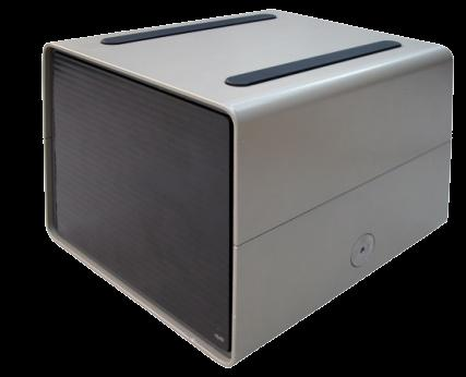
23 2004 RADAR 24 PLANAR Much lower power output; conform ETSI and FCC Replaces the radar 24 wave guide antenna Same performance and accuracy Same 24 GHz frequency Same fixed angle across the road as the wave guide version 23

24 RADAR 24 RESULT PHOTO S 24

25 RADAR 24 FIP WITH SECONDARY METHOD With road markers for secondary speed calculation in unmanned use. The speed of the vehicle can be calculated by measuring the travelled distance between on the 1 st and 2 nd image. A fixed interval setting must be set. RADAR DEVICES 25


26 PARABOLIC RADAR 13 GHZ AND 24 GHZ For use above the road; single lane monitoring 13 GHz 24 GHz 26


27 PARABOLIC RADAR PLANAR For use above the road; single lane monitoring Flat design is more compact ETSI en FCC compliant 27

28 PARABOLIC RADAR FOR OVERHEAD USE 28


29 PARABOLIC RADAR RESULT PHOTO S 29

30 PARABOLIC RADAR RESULT PHOTO S 30


31 2005 LOOPLESS TRIGGER RADAR 31


32 LTR SET-UP FOR SINGLE OR MULTIPLE LANES LTR angle settings are flexible and are set for each individual LTR for each individual lane, depending on height position, distance to centre of the lane, etc. 32
33 LTR ALIGNMENT Precise and accurate alignment with webcam RADAR DEVICES 33

34 LTR VEHICLE MEASUREMENT The footprint length can vary from roughly 6 to 25 meters depending on different installation situations. Start measurement at A Triggerpoint at B End measurement C Vx Receding vehicle A B C


35 LTR VEHICLE MEASUREMENT Start measurement at A Triggerpoint at B End measurement C Vx C B A Approaching vehicle
36 LTR SIGNALS Yellow = speed Red = LTR signal Green = trigger Blue = distance A-speed V-speed 36
37 LTR MODULATION The modulation has 4 discrete frequencies that are controlled by the LTR software. The channels are fixed by the program code (version). The difference in frequency varies from about 3 MHz to about 25 MHz. The oscillator is temperature stabilized. 37

38 LTR MODULATION A spectrum analyzer shows the signals measured on the DSP board. When operational, the DSP software is responsible for modulation and digitization. The modulation plan provides 4 distinct frequencies. The difference between these 4 frequencies is the basis for the distance measurement. Example of a spectrum scan 38

39 LTR MODULATION The purple curve is the modulation voltage The yellow and cyan curves are the signals on the I and Q channel The 90 degrees lag of the cyan signal is also visible A change in direction of the target will show a lag in the yellow signal DSP board signals 39

40 EXAMPLE LTR ON OVERHEAD MAST ARM 40


41 LTR RESULTS RED LIGHT ENFORCEMENT 41


42 LTR APPLICATIONS Red light Speed Emergency lane Buslane City centre environment zone Access Control Section control.. 42
43 2012 RT2 RADAR Simultaneously measures own speed, overtaking speed and distance in moving mode Measures speed and distance in stationary mode Selftest starting at front end to check system 43
44 RT2 TECHNICAL SPECIFICATIONS Type : Planar Patch Array Antenna beam : 5 horizontal, 20 vertical Squint angle : 20 Setting angle : parallel to road axis Measuring direction moving : receding (approaching is approval pending) stationary : approaching, receding or both Lane coverage : up to 4 lanes (stationary measurements) Positioning : aligned at road side for stationary measurements; : fixed radar position in car for moving measurements Transmission class : K-band Max. transmit power : 20 dbm (EIRP) ETSI compliant with 250 MHz bandwidth Operating temperature : in operation -25 to +60 RADAR DEVICES 44


45 RT2 MOVING ENFORCEMENT Overtaking speed Measures its own speed, and simultaneously measures the speed of the overtaking vehicle Measures the distance to the offending vehicle Own speed 45
46 RT2 DETECTION IN MOVING MODE Receding vehicle (low speed difference) Approaching vehicle (high speed difference) 46

47 2013 RT3 TRACKING RADAR Wide radar beam of approx. 70 degrees Speed detection Direction sensing Tracks up to 12 vehicles simultaneously Automatic angle measurement for speed calculation Selftest starting at front end Automatic alignment with traffic flow. 47
48 RADAR FRONT END Internal/external test Internal self test (electronic tuning fork) direct on mixer diodes. 48

49 RADAR FMCW Speed and ranging with an FMCW radar system 50 MHz 49

50 RADAR ANGLE MEASUREMENT Wavefront detectors Interferometry / monopulse t t + δt 50
51 TECHNICAL SPECIFICATIONS Transmit frequency: GHz GHz, GHz, GHz, GHz and GHz Maximum transmit power: 20dBm (EIRP) ETSI 300/400 en FCC compliant Antenna beam horizontal: 70º vertical: 11º Detection range: >70m Speed range: up to 300 km/h Direction sensing: approaching/receding Number of tracked vehicles : 12 (16 optional) Number of lanes to be observed: up to 4 Separation of targets: by speed and/or distance Installation height: 3 to 6m Operating temperature: -25 to
52 MEASUREMENT SINGLE VEHICLE Speed raw single vehicle 52

53 MEASUREMENT SINGLE VEHICLE Speed tracked single vehicle 53
54 MULTIPLE VEHICLES Speed raw multiple vehicles 54
55 MULTIPLE VEHICLES Speed tracked multiple vehicles 55

56 MULTIPLE VEHICLES Quality multiple vehicles 56
57 MULTIPLE VEHICLES Power level multiple vehicles 57
58 MULTIPLE VEHICLES Top view multiple vehicles 58
59 RT3 MULTIPLE VEHICLE TRACKING RADAR Wide angle, radar beam width of 70 Distance measurement Angle measurement Speed measurement Speed measurement in 2 directions State of the art technology 59
60 SINGLE POLE INSTALLATION 60
61 RT3 RED LIGHT SITUATION Detection line for camera trigger point Position of the detection line depends on local regulations/legislation 61

62 RT3 RADAR RESULT PHOTO S 62

63 TRACKING MULTIPLE VEHICLES The RT3 tracking radar provides lane indication The RT3 tracking radar can identify the offending vehicle RADAR DEVICES 63
64 SUMMARY Radar sensor has to be able to identify the vehicle for which it has measured the speed. To make identification possible it is necessary to use modulated radar systems. Modulated radar technology in 24 GHz is already available today. Used frequencies should be left unspecified but should meet local/ international regulations. Selftests with electronic tuning fork can be performed manually and/or automatically. A mechanical tuning fork is not possible because of complexity of radar signals. Continuous wave radars can not identify the offending vehicle without the use of a template. Suggestion for the future is to only use radars that enable the system to identify the offending vehicle. 64
65 Q & A 65

66 THANK YOU FOR YOUR ATTENTION 66
Features. Applications. Description. Blockdiagram. K-LC1a RADAR TRANSCEIVER. Datasheet
 Features 24 GHz K-band miniature transceiver 180MHz sweep FM input (n.a. for K-LC1a_V2) Dual 4 patch antenna Single balanced mixer with 50MHz bandwidth Beam aperture 80 /34 15dBm EIRP output power 25x25mm
siemens.com/mobility Radar detectors of the Heimdall family High detection rate, easy installation
 siemens.com/mobility Radar detectors of the Heimdall family High detection rate, easy installation Heimdall radar detectors from Siemens: A family that provides valuable benefits, Heimdall is the watchman
Various Technics of Liquids and Solids Level Measurements. (Part 3)
") (Part 3) In part one of this series of articles, level measurement using a floating system was discusses and the instruments were recommended for each application. In the second part of these articles,
(Part 3) In part one of this series of articles, level measurement using a floating system was discusses and the instruments were recommended for each application. In the second part of these articles,
MSAN-001 X-Band Microwave Motion Sensor Module Application Note
 1. Introduction HB Series of microwave motion sensor module are X-Band Mono-static DRO Doppler transceiver front-end module. These modules are designed for movement detection, like intruder alarms, occupancy
SmartDiagnostics Application Note Wireless Interference
 SmartDiagnostics Application Note Wireless Interference Publication Date: May 27, 2015 KCF Technologies, Inc. Background The SmartDiagnostics wireless network is an easy to install, end-to-end machine
Contents. Preface. xiii. Part I 1
 Contents Preface xiii Part I 1 Chapter 1 Introduction to Frequency-Modulated Continuous-Wave 3 Radar 1.1 Brief History 3 1.2 Examples of Use of FMCW Radar 5 1.2.1 Radio Altimeters 5 1.2.2 Level-Measuring
Antenna Deployment Technical Brief
 ProCurve Networking Antenna Deployment Technical Brief Introduction... 2 Antenna types... 2 Omni directional antennas... 2 Directional antennas... 2 Diversity antennas... 3 High gain directional antennas...
www.innosent.de isys-4001 speed- and distance detector
 www.innosent.de isys-4001 speed- and distance detector www.innosent.de isys-4001 speed and distance sensor typical applications The isys-4001 can be used in applications where movement, speed or distance
TCB Workshop. Unlicensed National Information Infrastructure Devices (U-NII)/Dynamic Frequency Selection (DFS)
/Dynamic Frequency Selection (DFS)") 1 TCB Workshop Unlicensed National Information Infrastructure Devices (U-NII)/Dynamic Frequency Selection (DFS) Andrew Leimer Office of Engineering and Technology/Equipment Authorization Branch FCC Laboratory
1 TCB Workshop Unlicensed National Information Infrastructure Devices (U-NII)/Dynamic Frequency Selection (DFS) Andrew Leimer Office of Engineering and Technology/Equipment Authorization Branch FCC Laboratory
INTRODUCTION FIGURE 1 1. Cosmic Rays. Gamma Rays. X-Rays. Ultraviolet Violet Blue Green Yellow Orange Red Infrared. Ultraviolet.
 INTRODUCTION Fibre optics behave quite different to metal cables. The concept of information transmission is the same though. We need to take a "carrier" signal, identify a signal parameter we can modulate,
Case Study Competition 2013. Be an engineer of the future! Innovating cars using the latest instrumentation!
 Case Study Competition 2013 Be an engineer of the future! Innovating cars using the latest instrumentation! The scenario You are engineers working on a project team that is tasked with the development
Projects. Objective To gain hands-on design and measurement experience with real-world applications. Contents
 Projects Contents 9-1 INTRODUCTION...................... 43 9-2 PROJECTS......................... 43 9-2.1 Alarm Radar Sensor................ 43 9-2.2 Microwave FM Communication Link....... 46 9-2.3 Optical
RF Network Analyzer Basics
 RF Network Analyzer Basics A tutorial, information and overview about the basics of the RF Network Analyzer. What is a Network Analyzer and how to use them, to include the Scalar Network Analyzer (SNA),
Synthetic Sensing: Proximity / Distance Sensors
 Synthetic Sensing: Proximity / Distance Sensors MediaRobotics Lab, February 2010 Proximity detection is dependent on the object of interest. One size does not fit all For non-contact distance measurement,
A comparison of radio direction-finding technologies. Paul Denisowski, Applications Engineer Rohde & Schwarz
 A comparison of radio direction-finding technologies Paul Denisowski, Applications Engineer Rohde & Schwarz Topics General introduction to radiolocation Manual DF techniques Doppler DF Time difference
LTCC Short Range Radar Sensor for Automotive Applications at 24 GHz
 LTCC Short Range Radar Sensor for Automotive Applications at 24 GHz P. Uhlig, C. Günner, S. Holzwarth, J. Kassner, R. Kulke, A. Lauer, M. Rittweger IMST GmbH, D-47475 Kamp-Lintfort, Germany, www.ltcc.de
Avaya WLAN 9100 External Antennas for use with the WAO-9122 Access Point
 Avaya WLAN 9100 External Antennas for use with the WAO-9122 Access Point Overview To optimize the overall performance of a WLAN in an outdoor deployment it is important to understand how to maximize coverage
Antenna Trainer EAN. www.edibon.com. Technical Teaching Equipment INTRODUCTION
 Antenna Trainer EAN Technical Teaching Equipment Products Products range Units 3.-Communications INTRODUCTION Antennas are the main element of aerial communications. They are the transition between a transmission
AN1200.04. Application Note: FCC Regulations for ISM Band Devices: 902-928 MHz. FCC Regulations for ISM Band Devices: 902-928 MHz
 AN1200.04 Application Note: FCC Regulations for ISM Band Devices: Copyright Semtech 2006 1 of 15 www.semtech.com 1 Table of Contents 1 Table of Contents...2 1.1 Index of Figures...2 1.2 Index of Tables...2
Application Note AN-00126
 Considerations for Operation within the 902-928MHz Band Application Note AN-00126 Introduction This application note is designed to give the reader a basic understanding of the legal and technical considerations
Project Documentation EKTSDG-010000 Target Simulator Doppler Generator
 Project Documentation EKTSDG-010000 Target Simulator Doppler Generator Project Number: SMS Project Number: Project Title: Handheld Radar Target Simulator Doppler Generator Keyword(s): Electronic Radar
You will need the following pieces of equipment to complete this experiment:
 UNIVERSITY OF TORONTO FACULTY OF APPLIED SCIENCE AND ENGINEERING The Edward S. Rogers Sr. Department of Electrical and Computer Engineering ECE422H1S: RADIO AND MICROWAVE WIRELESS SYSTEMS EXPERIMENT 3:
Electromagnetic (EM) waves. Electric and Magnetic Fields. L 30 Electricity and Magnetism [7] James Clerk Maxwell (1831-1879)
![Electromagnetic (EM) waves. Electric and Magnetic Fields. L 30 Electricity and Magnetism [7] James Clerk Maxwell (1831-1879)](/thumbs/40/20813653.jpg "Electromagnetic (EM) waves. Electric and Magnetic Fields. L 30 Electricity and Magnetism [7] James Clerk Maxwell (1831-1879)") L 30 Electricity and Magnetism [7] ELECTROMAGNETIC WAVES Faraday laid the groundwork with his discovery of electromagnetic induction Maxwell added the last piece of the puzzle Heinrich Hertz made the experimental
L 30 Electricity and Magnetism [7] ELECTROMAGNETIC WAVES Faraday laid the groundwork with his discovery of electromagnetic induction Maxwell added the last piece of the puzzle Heinrich Hertz made the experimental
ENGINEERING METROLOGY
 ENGINEERING METROLOGY ACADEMIC YEAR 92-93, SEMESTER ONE COORDINATE MEASURING MACHINES OPTICAL MEASUREMENT SYSTEMS; DEPARTMENT OF MECHANICAL ENGINEERING ISFAHAN UNIVERSITY OF TECHNOLOGY Coordinate Measuring
What is the Real Cost of Poor Quality Antennas?
 White Paper What is the Real Cost of Poor Quality Antennas? Jim Syme Product Line Manager, Microwave Systems October 2015 Contents Introduction 3 The Theory behind Compliance 3 The Real World 4 Conclusion
Department of Information Engineering University of Pisa. Automotive Radar. Maria S. Greco. 2012 IEEE Radar Conference, May 7-11, Atlanta
 Department of Information Engineering University of Pisa. Automotive Radar Maria S. Greco Automotive RADAR Why? Automotive RADARs as core sensor (range, speed) of driver assistance systems: long range
Drones Jammer. A simple drone Jammer designed to hack unwelcomed civilian drones within your backyard range.
 Drones Jammer A simple drone Jammer designed to hack unwelcomed civilian drones within your backyard range. Designed by: Ahmad Jisrawi Jisrawi@gmail.com https://twitter.com/ajisrawi What are Jammers? Commonly
RECOMMENDATION ITU-R M.1453-1 * Transport information and control systems Dedicated short range communications at 5.8 GHz
 Rec. ITU-R M.1453-1 1 RECOMMENDATION ITU-R M.1453-1 * Transport and control systems Dedicated short range communications at 5.8 GHz (Question ITU-R 205/8) (2000-2002) The ITU Radiocommunication Assembly,
102 26-m Antenna Subnet Telecommunications Interfaces
 DSMS Telecommunications Link Design Handbook 26-m Antenna Subnet Telecommunications Interfaces Effective November 30, 2000 Document Owner: Approved by: Released by: [Signature on file in TMOD Library]
Spectrum and Power Measurements Using the E6474A Wireless Network Optimization Platform
 Application Note Spectrum and Power Measurements Using the E6474A Wireless Network Optimization Platform By: Richard Komar Introduction With the rapid development of wireless technologies, it has become
DT3: RF On/Off Remote Control Technology. Rodney Singleton Joe Larsen Luis Garcia Rafael Ocampo Mike Moulton Eric Hatch
 DT3: RF On/Off Remote Control Technology Rodney Singleton Joe Larsen Luis Garcia Rafael Ocampo Mike Moulton Eric Hatch Agenda Radio Frequency Overview Frequency Selection Signals Methods Modulation Methods
Mobile use, radio signals and health
 Mobile use, radio signals and health Mobile use, radio signals and health How does the mobile network work? Since the 1970s, the use of various types of radio transmitters has risen dramatically, to the
Technical Datasheet Scalar Network Analyzer Model 8003-10 MHz to 40 GHz
 Technical Datasheet Scalar Network Analyzer Model 8003-10 MHz to 40 GHz The Giga-tronics Model 8003 Precision Scalar Network Analyzer combines a 90 db wide dynamic range with the accuracy and linearity
TX GSM SMS Auto-dial Alarm System. Installation and User Manual
 TX GSM SMS Auto-dial Alarm System Installation and User Manual Product Features: 1. 16 wireless zones, 3 wired zones alarm system, suitable for small to medium size offices and homes. 2. The system uses
Dynamic Frequency Selection (DFS) and the 5GHz Unlicensed Band
 and the 5GHz Unlicensed Band") Dynamic Frequency Selection (DFS) and the 5GHz Unlicensed Band by Mark Briggs, Principal Engineer, Elliott Laboratories- An NTS Company Note: This article combines the content from several papers released
Dynamic Frequency Selection (DFS) and the 5GHz Unlicensed Band by Mark Briggs, Principal Engineer, Elliott Laboratories- An NTS Company Note: This article combines the content from several papers released
Application Note Noise Frequently Asked Questions
 : What is? is a random signal inherent in all physical components. It directly limits the detection and processing of all information. The common form of noise is white Gaussian due to the many random
A Surveillance Robot with Climbing Capabilities for Home Security
 Available Online at www.ijcsmc.com International Journal of Computer Science and Mobile Computing A Monthly Journal of Computer Science and Information Technology IJCSMC, Vol. 2, Issue. 11, November 2013,
primary SURVEILLANCE 3D RADAR
 AIR TRAFFIC MANAGEMENT AIRport & ROUTE primary SURVEILLANCE 3D RADAR Supplying ATM systems around the world for more than 90 years indracompany.com AIRport & ROUTE primary SURVEILLANCE 3D RADAR Latest
FACTORY AUTOMATION EXPERTISE AND SERVICE OPEN DOORS RADAR SENSORS FROM PEPPERL+FUCHS
 FACTORY AUTOMATION EXPERTISE AND SERVICE OPEN DOORS RADAR SENSORS FROM PEPPERL+FUCHS RADAR MOTION SENSORS FROM PEPPERL+FUCHS A FAMILY OF RADAR SENSORS THAT IS EQUAL TO ANY CHALLENGE Since radar sensors
Design Considerations for RF Energy Harvesting Devices
 Design Considerations for RF Energy Harvesting Devices Harry Ostaffe Director, Marketing & Business Development 1 Overview RF energy is generally very low Direct-power at close range to a transmitter Energy
Interferometers. OBJECTIVES To examine the operation of several kinds of interferometers. d sin = n (1)
") Interferometers The true worth of an experimenter consists in his pursuing not only what he seeks in his experiment, but also what he did not seek. Claude Bernard (1813-1878) OBJECTIVES To examine the
Interferometers The true worth of an experimenter consists in his pursuing not only what he seeks in his experiment, but also what he did not seek. Claude Bernard (1813-1878) OBJECTIVES To examine the
DRONE DETECTION RADAR
 DRONE DETECTION RADAR MEETING TODAY S CHALLENGES Drones are increasingly becoming wide spread. They ve become affordable, easy to obtain and simple to fly. This creates new opportunities, but also poses
FIRERAY 2000 Installation Guide
 FIRERAY 2000 Installation Guide Features Range 33ft to 330 ft. 24Vdc operation Selectable alarm thresholds Low current consumption Ground level electronics Manual or Automatic reset System Description
The Phase Modulator In NBFM Voice Communication Systems
 The Phase Modulator In NBFM Voice Communication Systems Virgil Leenerts 8 March 5 The phase modulator has been a point of discussion as to why it is used and not a frequency modulator in what are called
Design and Certification of ASH Radio Systems for Japan
 Design and Certification of ASH Radio Systems for Japan RFM s second-generation ASH radio hybrids are being used in a wide variety of applications in Japan, operating under the Japanese BIJAKU radio regulations.
3D LANZA FAMILY RADARS
 DEFENSE AND SECURITY 3D LANZA FAMILY RADARS Defense and security in five continents indracompany.com LANZA-MRR/ LANZA-LRR 3D LANZA FAMILY RADARS Radar 3D mobile Long range 3D radar Radar 3D naval State-of-the
Email: tjohn@mail.nplindia.ernet.in
 USE OF VIRTUAL INSTRUMENTS IN RADIO AND ATMOSPHERIC EXPERIMENTS P.N. VIJAYAKUMAR, THOMAS JOHN AND S.C. GARG RADIO AND ATMOSPHERIC SCIENCE DIVISION, NATIONAL PHYSICAL LABORATORY, NEW DELHI 110012, INDIA
INTERFERENCE OF SOUND WAVES
 1/2016 Sound 1/8 INTERFERENCE OF SOUND WAVES PURPOSE: To measure the wavelength, frequency, and propagation speed of ultrasonic sound waves and to observe interference phenomena with ultrasonic sound waves.
A receiver TDC chip set for accurate pulsed time-of-flight laser ranging
 A receiver TDC chip set for accurate pulsed time-of-flight laser ranging Juha Kostamovaara, Sami Kurtti, Jussi-Pekka Jansson University of Oulu, Department of Electrical Engineering, Electronics Laboratory,
Embedded Linux RADAR device
 Embedded Linux Conference Europe 2012 (Barcelona - November 5-7) Embedded Linux RADAR device Taking advantage on Linaro tools and HTML5 AJAX real-time visualization Agustí FONTQUERNI GORCHS af@iseebcn.com
The Use of Above Ground Vehicle Detectors
 Traffic Advisory Leaflet 16/99 December 1999 The Use of Above Ground Vehicle Detectors Introduction Responsive traffic signal systems are a key component in managing the safe and efficient progress of
A PHOTOGRAMMETRIC APPRAOCH FOR AUTOMATIC TRAFFIC ASSESSMENT USING CONVENTIONAL CCTV CAMERA
 A PHOTOGRAMMETRIC APPRAOCH FOR AUTOMATIC TRAFFIC ASSESSMENT USING CONVENTIONAL CCTV CAMERA N. Zarrinpanjeh a, F. Dadrassjavan b, H. Fattahi c * a Islamic Azad University of Qazvin - nzarrin@qiau.ac.ir
Antenna Properties and their impact on Wireless System Performance. Dr. Steven R. Best. Cushcraft Corporation 48 Perimeter Road Manchester, NH 03013
 Antenna Properties and their impact on Wireless System Performance Dr. Steven R. Best Cushcraft Corporation 48 Perimeter Road Manchester, NH 03013 Phone (603) 627-7877 FAX: (603) 627-1764 Email: sbest@cushcraft.com
How To Control Gimbal
 Tarot 2-Axis Brushless Gimbal for Gopro User Manual V1.0 1. Introduction Tarot T-2D gimbal is designed for the Gopro Hero3, which is widely used in film, television productions, advertising aerial photography,
DRS-6/1 Doppler Radar Sensor
 DRS-6/1 Doppler Radar Sensor B+S Software und Messtechnik GmbH Lochhamer Schlag 17 D-82166 Graefelfing Germany October 1999 User's Manual DRS-6 SENSOR for speed measurements 1. DRS-6 Functional Description
Vehicle GPS Tracker GP2068
 Vehicle GPS Tracker GP2068-1 - 1 PRODUCT INTRODUCTION 1.1 Features of unpacking 1.2 Brief introduction This newly launched vehicle GPS tracker-gp2068 is a GPRS based tracking system. It is for individual
Vehicle GPS Tracker GP268. GP268 Vehicle GPS/GPRS Tracking and Monitoring System Presentation July, 2009
 Vehicle GPS Tracker GP268 Winwill World Co., Ltd 2008 Website: www.winwillworld.com Inquire now: sales@winwillworld.com - 1 - 1 PRODUCT INTRODUCTION 1.1 Features of unpacking 1.2 Brief introduction GP268,
Ultra Wideband Signal Impact on IEEE802.11b Network Performance
 Ultra Wideband Signal Impact on IEEE802.11b Network Performance Matti Hämäläinen 1, Jani Saloranta 1, Juha-Pekka Mäkelä 1, Tero Patana 2, Ian Oppermann 1 1 Centre for Wireless Communications (CWC), University
Selecting Receiving Antennas for Radio Tracking
 Selecting Receiving Antennas for Radio Tracking Larry B Kuechle, Advanced Telemetry Systems, Inc. Isanti, Minnesota 55040 lkuechle@atstrack.com The receiving antenna is an integral part of any radio location
Electromagnetic radiation exposure: assessment against ACA mandated limits
 Electromagnetic radiation exposure: assessment against ACA mandated limits General radio services (operating above 0 MHz) (Edition May 0) Disclaimer Unless otherwise specified, the information contained
NAVICOM DYNAMICS RTK BASE STATION INSTALLATION AND COMMISSIONING INSTRUCTIONS
 NAVICOM DYNAMICS RTK BASE STATION INSTALLATION AND COMMISSIONING INSTRUCTIONS 1. Locate a suitable position inside the building to install the Base Station enclosure where mains power (240V AC) is available
Radio-Tracking of Birds: Regulation and Ruling of Radio Frequencies
 Radio-Tracking of Birds: Regulation and Ruling of Radio Frequencies Animal Tracking workshop @ Hula Valley 7-9 Nov 1 Dr. Haim Mazar; Israeli Ministry of Communications Vice Chairman ITU-R Study Group 1
Constructing a precision SWR meter and antenna analyzer. Mike Brink HNF, Design Technologist.
 Constructing a precision SWR meter and antenna analyzer. Mike Brink HNF, Design Technologist. Abstract. I have been asked to put together a detailed article on a SWR meter. In this article I will deal
Users Manual of GSM Home Alarm System with Photo-taken
 GSM-IV REMOTE CAMERA MANNAL The Excellent GSM + Camera alarm system bases on the GSM network, integrates the communication technology, can automatic screen a photo with the intruder or burglar, and send
Experiment 5. Lasers and laser mode structure
 Northeastern University, PHYS5318 Spring 2014, 1 1. Introduction Experiment 5. Lasers and laser mode structure The laser is a very important optical tool that has found widespread use in science and industry,
Transmitting Live Aircraft Security Data by 3G Unlocking the Potential of 3G Developing an Air Traffic Management (ATM) Security System
 Security System") Transmitting Live Aircraft Security Data by 3G Steve Lane, Commercial Director at electronic design consultancy Triteq, talks about how commercial 3G mobile phone technology has been adapted to monitor
Transmitting Live Aircraft Security Data by 3G Steve Lane, Commercial Director at electronic design consultancy Triteq, talks about how commercial 3G mobile phone technology has been adapted to monitor
Speed Detection Operators Module
 NZ POLICE CALIBRATION UNIT Speed Detection Operators Module PHRIS Code 2277 DUT 244 Table of Contents 1. About this module... 3 2. Background... 4 3. Radar speed detection... 7 4. Self-paced test Radar...
Introduction Ericsson Handheld Telephone 1341-B
 Ericsson Handheld Telephone 1341-B 2 Contents General 5 The Mobile Telephone Network 6 Base Station and Cell 7 Radio Channels 7 Radio Coverage 8 Transmission Control and Communication 9 Quality Control
Technical Data FLIR E40bx (incl. Wi-Fi)
") Technical Data FLIR E40bx (incl. Wi-Fi) Part number: 64501-0501 Copyright 2013, FLIR Systems, Inc. All rights reserved worldwide. Names and marks appearing herein are either registered trademarks or trademarks
Technical Data FLIR E40bx (incl. Wi-Fi) Part number: 64501-0501 Copyright 2013, FLIR Systems, Inc. All rights reserved worldwide. Names and marks appearing herein are either registered trademarks or trademarks
BASICS OF C & Ku BAND TRANSMISSIONS & LNBs
 Page 1 of 6 BASICS OF C & Ku BAND TRANSMISSIONS & LNBs A satellite broadcasts a few watts of microwave signals from the geostationary orbit 36,000 kilometers above the earth. The transmissions are also
Agilent AN 1316 Optimizing Spectrum Analyzer Amplitude Accuracy
 Agilent AN 1316 Optimizing Spectrum Analyzer Amplitude Accuracy Application Note RF & Microwave Spectrum Analyzers Table of Contents 3 3 4 4 5 7 8 8 13 13 14 16 16 Introduction Absolute versus relative
Features. Applications. Transmitter. Receiver. General Description MINIATURE MODULE. QM MODULATION OPTIMAL RANGE 1000m
 Features MINIATURE MODULE QM MODULATION OPTIMAL RANGE 1000m 433.05 434.79 ISM BAND 34 CHANNELS AVAILABLE SINGLE SUPPLY VOLTAGE Applications IN VEHICLE TELEMETRY SYSTEMS WIRELESS NETWORKING DOMESTIC AND
Antenna Diversity in Wireless Local Area Network Devices
 Antenna Diversity in Wireless Local Area Network Devices Frank M. Caimi, Ph.D. Kerry L. Greer Jason M. Hendler January 2002 Introduction Antenna diversity has been used in wireless communication systems
JOINT EXPERT GROUP AND 5G VISION WORKING GROUP WORKSHOP. The Killer Application of Millimeter Wave
 JOINT EXPERT GROUP AND 5G VISION WORKING GROUP WORKSHOP V2X Communications: The Killer Application of Millimeter Wave Nuria González-Prelcic Robert W. Heath Jr. Jorge M. El MalekVázquez nuria@gts.uvigo.es
LED red (-): Measuring value < lower tolerance threshold LED red (+): Measuring value > upper tolerance threshold. Page 1/6
: Measuring value < lower tolerance threshold LED red (+): Measuring value > upper tolerance threshold. Page 1/6") L-LAS Series L-LAS-LT-165-CL - Line laser 1 mw, laser class 2 - Visible laser line (red light 670 nm), typ. 2 mm x 3 mm - Reference distance approx. 165 mm - Measuring range typ. 65... 265 mm - Resolution
L-LAS Series L-LAS-LT-165-CL - Line laser 1 mw, laser class 2 - Visible laser line (red light 670 nm), typ. 2 mm x 3 mm - Reference distance approx. 165 mm - Measuring range typ. 65... 265 mm - Resolution
Chapter 4 Solution to Problems
 Chapter 4 Solution to Problems Question #1. A C-band earth station has an antenna with a transmit gain of 54 db. The transmitter output power is set to 100 W at a frequency of 6.100 GHz. The signal is
Application Note AN-00125
 Considerations for Operation within the 260 470MHz Band Introduction This application note is designed to give the reader a basic understanding of the legal and technical considerations for operation of
ECC/DEC/(04)08 ELECTRONIC COMMUNICATIONS COMMITTEE
08 ELECTRONIC COMMUNICATIONS COMMITTEE") ELECTRONIC COMMUNICATIONS COMMITTEE ECC Decision of 09 July 2004 on the harmonised use of the 5 GHz frequency bands for the implementation of Wireless Access Systems including Radio Local Area Networks
ELECTRONIC COMMUNICATIONS COMMITTEE ECC Decision of 09 July 2004 on the harmonised use of the 5 GHz frequency bands for the implementation of Wireless Access Systems including Radio Local Area Networks
L-LAS-TB-CL serie. laser light curtains for inline measuring tasks
 L-LAS-TB-CL serie laser light curtains for inline measuring tasks Maximum distance 2.000 mm Measurement range 6 up to 98 mm Resolution up to 4 µm up to 1,5 khz scan rate 0-10 V or 4-20 ma analogue output
Applications in EMC testing. Outline. Antennas for EMC Testing. Terminology
 Antennas for EMC Testing Zhong Chen ETS-Lindgren 1301 Arrow Point Drive Cedar Park, TX 78613 Zhong.Chen@ets-lindgren.com Outline EMC Terms and Definitions Typical EMC Antennas Calibration of EMC Antennas
Wireless Medical Telemetry Laboratory
 Wireless Medical Telemetry Laboratory 0 Introduction The development of wireless medical telemetry has become an increasingly popular application in recent years. As the elderly population continues to
Automatic Distance/Time Speedmeter Handbook (Second Edition) Provisional
 Provisional") Automatic Distance/Time Speedmeter Handbook (Second Edition) Provisional A Guide to Type-Approval Procedures for Automatic Distance/Time Speedmeters Used for Road Traffic Law Enforcement in Great Britain
Automatic Distance/Time Speedmeter Handbook (Second Edition) Provisional A Guide to Type-Approval Procedures for Automatic Distance/Time Speedmeters Used for Road Traffic Law Enforcement in Great Britain
ETSI EN 300 328-1 V1.2.2 (2000-07)
") EN 300 328-1 V1.2.2 (2000-07) European Standard (Telecommunications series) Electromagnetic compatibility and Radio spectrum Matters (ERM); Wideband Transmission systems; data transmission equipment operating
EN 300 328-1 V1.2.2 (2000-07) European Standard (Telecommunications series) Electromagnetic compatibility and Radio spectrum Matters (ERM); Wideband Transmission systems; data transmission equipment operating
Quest- 1 Satellite Functional Description
 Quest- 1 Satellite Functional Description Overview The Quest- 1 Satellite is based on the CubeSat Standard that measures 10 cm x 10 cm x 10 cm and weighs less than 1.33 kilograms. The Quest- 1 Satellite
Universal Form-factor. Wi Fi Troubleshooting Made Easy
 AirMedic USB AirMedic USB is a powerful, easy-touse and affordable spectrum analysis tool that brings Wi-Fi troubleshooting to entry-level users. Built upon AirMagnet expertise in Wi-Fi troubleshooting,
EE302 Lesson 14: Antennas
 EE302 Lesson 14: Antennas Loaded antennas /4 antennas are desirable because their impedance is purely resistive. At low frequencies, full /4 antennas are sometime impractical (especially in mobile applications).
SPYTEC 3000 The system for GSM communication monitoring
 SPYTEC 3000 The system for GSM communication monitoring The SPYTEC 3000 system is intended for passive (if system encryption is absent of if A5.2 encryption is used) or semi-active (if A5.1 encryption
WIRELESS INSTRUMENTATION TECHNOLOGY
 BS&B WIRELESS, L.L.C. BS&B WIRELESS, L.L.C. WIRELESS INSTRUMENTATION TECHNOLOGY Printed February 2004 BS&B WIRELESS, L.L.C. 7422-B East 46th Place, Tulsa, OK74145 Phone: 918-622-5950 Fax: 918-665-3904
TESTS OF 1 MHZ SIGNAL SOURCE FOR SPECTRUM ANALYZER CALIBRATION 7/8/08 Sam Wetterlin
 TESTS OF 1 MHZ SIGNAL SOURCE FOR SPECTRUM ANALYZER CALIBRATION 7/8/08 Sam Wetterlin (Updated 7/19/08 to delete sine wave output) I constructed the 1 MHz square wave generator shown in the Appendix. This
Doppler. Doppler. Doppler shift. Doppler Frequency. Doppler shift. Doppler shift. Chapter 19
 Doppler Doppler Chapter 19 A moving train with a trumpet player holding the same tone for a very long time travels from your left to your right. The tone changes relative the motion of you (receiver) and
PHYS 222 Spring 2012 Final Exam. Closed books, notes, etc. No electronic device except a calculator.
 PHYS 222 Spring 2012 Final Exam Closed books, notes, etc. No electronic device except a calculator. NAME: (all questions with equal weight) 1. If the distance between two point charges is tripled, the
RF Energy Harvesting and Wireless Power for Low-Power Applications
 RF Energy Harvesting and Wireless Power for Low-Power Applications Emerging Technology P2100 Powerharvester TX91501 Powercaster P2110 Powerharvester P2110 Powerharvester April 6 2012 1 Powercast Technology
Electromagnetic radiation exposure: assessment against ACA mandated limits
 Electromagnetic radiation exposure: assessment against ACA mandated limits Paging services (Edition May 2002) Disclaimer Unless otherwise specified, the information contained in these guidelines is intended
Stationary uplift measurement as a diagnostic tool for pantograph monitoring. H. Möller, H. Maly, B. Sarnes
 Stationary uplift measurement as a diagnostic tool for pantograph monitoring H. Möller, H. Maly, B. Sarnes Abstract: The present paper describes a prototype of an automatic uplift measurement system capable
Correlation between OATS, Fully Anechoic Room and GTEM Radiated Emissions
 Correlation between OATS, Fully Anechoic Room and GTEM Radiated Emissions Stephen Clay Introduction: Just a few words about myself. My name is Steve Clay and I work for Nokia Mobile Phones, and it is my
GLOBAL COLLEGE OF ENGINEERING &TECHNOLOGY: YSR DIST. Unit VII Fiber Optics Engineering Physics
 Introduction Fiber optics deals with the light propagation through thin glass fibers. Fiber optics plays an important role in the field of communication to transmit voice, television and digital data signals
Tri-Band RF Transceivers for Dynamic Spectrum Access. By Nishant Kumar and Yu-Dong Yao
 Tri-Band RF Transceivers for Dynamic Spectrum Access By Nishant Kumar and Yu-Dong Yao Presentation outline Introduction to WISELAB Active work at WISELAB Tri-band test bed Elements of the test bed Experimentation
Agilent N8973A, N8974A, N8975A NFA Series Noise Figure Analyzers. Data Sheet
 Agilent N8973A, N8974A, N8975A NFA Series Noise Figure Analyzers Data Sheet Specifications Specifications are only valid for the stated operating frequency, and apply over 0 C to +55 C unless otherwise
DVB-T Television Repeater Jim Andrews, KH6HTV
 AN-23 DTV Rptr.doc (6/1/2015) p. 1 of 5 Application Note AN-23 June, 2015 DVB-T Television Repeater Jim Andrews, KH6HTV Fig. 1 A 70cm, Digital TV Repeater, block diagram. The FCC allows licensed amateur
The World Smallest Automatic Satellite Antenna
 The World Smallest Automatic Satellite Antenna Background Plenty of good contents come from the sky. More and more people in Europe are getting bigger demand for satellite broadcasting. People want to