LAB MANUAL FOR CASE TOOLS LAB. IV B.Tech I SEM
|
|
|
- Emery Norton
- 7 years ago
- Views:
Transcription
 C.Ramauram (V), Ramachandrauram(M), Chittoor Dist-517 561 (2013-2014) LAB MANUAL FOR CASE TOOLS LAB IV B.")
1 Department of Computer Science & Engineering SWETHA INSTITUTE OF TECHNOLOGY& SCIENCE ( Approved by AICTE and Affiliated to JNTU-ANATAUR) C.Ramauram (V), Ramachandrauram(M), Chittoor Dist ( ) LAB MANUAL FOR CASE TOOLS LAB IV B.Tech I SEM N99A49G70E68S51
2 OBJECTIVES OF THE LAB 1.Documenting user requirements using the UML notation 2. Description of the various components of UML 3. The use of Use Cases AIMS OF UML 1. Models helps us to visualize a system as it is or an as we want it to be. 2. Models permit us to specify the structure or behavior of a system. 3. Models gives us a template guides us in constructing a system. 4. Models document the decisions we have made. REQUIREMENTS Hardware andsoftware required: 1. A working computer system with either Windows or Linux 2. Rational Rose Software or Visual Paradigm Software N99A49G70E68S51
3 N99A49G70E68S51 LAB SYLLABUS PROGRAMS (JNTU) Students are divided into batches of 5 each and each batch has to draw the following diagrams using UML for an ATM system whose description is given below. UML diagrams to be developed are: 1. Use Case Diagram. 2. Class Diagram. 3. Sequence Diagram. 4. Collaboration Diagram. 5. State Diagram 6. Activity Diagram. 7. Component Diagram 8. Deployment Diagram. Description for an ATM System The software to be designed will control a simulated automated teller machine (ATM) having a magnetic stripe reader for reading an ATM card, a customer console (keyboard and display) for interaction with the customer, a slot for depositing envelopes, a dispenser for cash (in multiples of Rs. 100, Rs. 500 and Rs. 1000), a printer for printing customer receipts, and a key-operated switch to allow an operator to start or stop the machine. The ATM will communicate with the bank's computer over an appropriate communication link. (The software on the latter is not part of the requirements for this problem.) The ATM will service one customer at a time. A customer will be required to insert an ATM card and enter a personal identification number (PIN) - both of which will be sent to the bank for validation as part of each transaction. The customer will then be able to perform one or more transactions. The card will be retained in the machine until the customer indicates that he/she desires no further transactions, at which point it will be returned - except as noted below. The ATM must be able to provide the following services to the customer: 1. A customer must be able to make a cash withdrawal from any suitable account linked to the card, in multiples of Rs. 100 or Rs. 500 or Rs Approval must be obtained from the bank before cash is dispensed. 2. A customer must be able to make a deposit to any account linked to the card, consisting of cash and/or checks in an envelope. The customer will enter the amount of the deposit into the ATM, subject to manual verification when the envelope is removed from the machine by an operator. Approval must be obtained from the bank before physically accepting the envelope. 3. A customer must be able to make a transfer of money between any two accounts linked to the card. 4. A customer must be able to make a balance inquiry of any account linked to the card. 5. A customer must be able to abort a transaction in progress by pressing the Cancel
4 key instead of responding to a request from the machine. The ATM will communicate each transaction to the bank and obtain verification that it was allowed by the bank. Ordinarily, a transaction will be considered complete by the bank once it has been approved. In the case of a deposit, a second message will be sent to the bank indicating that the customer has deposited the envelope. (If the customer fails to deposit the envelope within the timeout period, or presses cancel instead, no second message will be sent to the bank and the deposit will not be credited to the customer.) If the bank determines that the customer's PIN is invalid, the customer will be required to re-enter the PIN before a transaction can proceed. If the customer is unable to successfully enter the PIN after three tries, the card will be permanently retained by the machine, and the customer will have to contact the bank to get it back If a transaction fails for any reason other than an invalid PIN, the ATM will display an explanation of the problem, and will then ask the customer whether he/she wants to do another transaction. The ATM will provide the customer with a printed receipt for each successful transaction The ATM will have a key-operated switch that will allow an operator to start and stop the servicing of customers. After turning the switch to the "on" position, the operator will be required to verify and enter the total cash on hand. The machine can only be turned off when it is not servicing a customer. When the switch is moved to the "off" position, the machine will shut down, so that the operator may remove deposit envelopes and reload the machine with cash, blank receipts, etc.. N99A49G70E68S51
5 INTRODUCTION ABOUT LAB CASE tools known as Computer-aided software engineering tools is a kind of component-based development which allows its users to rapidly develop information systems. The main goal of case technology is the automation of the entire information systems development life cycle process using a set of integrated software tools, such as modeling, methodology and automatic code generation. Component based manufacturing has several advantages over custom development. The main advantages are the availability of high quality, defect free products at low cost and at a faster time. The prefabricated components are customized as per the requirements of the customers. The components used are pre-built, ready-tested and add value and differentiation by rapid customization to the targeted customers. However the products we get from case tools are only a skeleton of the final product required and allot of programming must be done by hand to get a fully finished, good product. Characteristics of CASE: Some of the characteristics of case tools It is a graphic oriented tool. It supports decomposition of process. Some typical CASE tools are: Unified Modeling Language Data modeling tools, and Source code generation tools Introduction to UML (Unified Modeling Language): The unified modeling language (UML) is a standard language for writing software blue prints. The UML is a language for Visualizing Specifying Constructing Documenting The artifacts of a software system: UML is a language that provides vocabulary and the rules for combing words in that vocabulary for the purpose of communication. A modeling language is a language whose vocabulary and rules focus on the concept and physical representation of a system. Vocabulary and rules of a language tell us how to create and real well formed models, but they don t tell you what model you should create and when should create them. Visualizing N99A49G70E68S51
6 The UML is more than just a bunch of graphical symbols. In UML each symbol has well defined semantics. In this manner one developer can write a model in the UML and another developer or even another tools can interpret the model unambiguously. Specifying UML is used for specifying means building models that are precise, unambiguous and complete. UML addresses the specification of all the important analysis, design and implementation decisions that must be made in developing and deploying a software intensive system. Constructing UML is not a visual programming language but its models can be directly connected to a variety of programming languages. This means that it is possible to map from a model in the UML to a programming language such as java, c++ or Visual Basic or even to tables in a relational database or the persistent store of an object-oriented database. This mapping permits forward engineering. The generation of code from a UML model into a programming language. The reverse engineering is also possible you can reconstruct a model from an implementation back into the UML. Documenting UML is a language for Documenting. A software organization produces all sorts of artifacts in addition to raw executable code. These artifacts include Requirements, Architecture, Design, Source code, Project plans, Test, Prototype, and Release. Such artifacts are not only the deliverables of a project, they are also critical in controlling, measuring and communicating about a system during its development and after its deployment. Conceptual model of the UML: To understand the UML, we need to form a conceptual model of the language and this requires learning three major elements. The UML Basic Building Blocks. The Rules that direct how those building blocks may be put together. Some common mechanisms that apply throughout the UML. As UML describes the real time systems it is very important to make a conceptual model and then proceed gradually. Conceptual model of UML can be mastered by learning the following three major elements: UML building blocks Rules to connect the building blocks. Common mechanisms of UML. UML building blocks. The building blocks of UML can be defined as: Things Relationships Page 6
7 Diagrams Things: Things are the most important building blocks of UML. Things can be: Structural Behavioral Grouping Annotational Structural things: Class: A class is the descriptor for a set of objects with similar structure, behavior, and relationships. It is represented by a rectangle. Interface: An interface is a specified for the externally-visible operations of a class, component, or other classifier (including subsystems) without specification of internal structure. It is represented by a circle. Relations: Association Dependency Generalization Realization In addition to this there are Directed Association Aggregation and Composition Association: An association is a structural relationship that specifies the relation between two objects when they are at the same level (peer level systems). An Association can specify the relationship, role of the class and Multiplicity. An Association used in class diagram, Component diagram, deployment diagram, usecase diagrams. The multiplicity can be represented as 1-1..*,*,0 1. Page 7
8 It is represented as follows: Directed Association: Links a semantic association between two classes in the UML diagram. Directed association is used in class diagram, Component diagram, deployment diagram, usecase diagrams. Aggregation: Links a semantic association between two classes in the UML diagram. Aggregation is used in class diagram. Composition: Links a semantic association between two classes in the UML diagram. Composition is used in class diagram. Generalization: Generalization is a specification relationship in which objects of the specialized element (the child) are substitutable for objects of the generalization element (the parent).it is used in class diagram. Dependency: A dependency is a semantic relationship in which if there is any change occurred in one object that may affect other object. Dependency is used in class diagram, Component diagram, deployment diagram, usecase diagrams Realization: Realization is a Specified tool that can be represented by providing a relationship with classifier. Dependency is used in class diagram, Component diagram, deployment diagram, usecase diagrams Class diagrams: A class diagram is that which represents a set of classes, interfaces, and collaborations and their relationships, graphically a class diagram is a collection of vertices and arcs. Page 8
9 It consists of three compartments. Name Attributes Operations Uses: A class diagram is used to model the static design view of a system. Object diagrams: An object diagram shares the same common properties of all other diagrams. ; Name Attributes Operations Uses: An object diagram is used to model the static design view of a system. UseCase Diagrams: A usecase diagram shares the common properties as all diagrams. It distinguishes in the contents of use cases, actors, dependency, and generalization relationships. Actor Uses: A Usecase diagram is used to model the static design view of a system. Interaction Diagrams: An Interaction diagram shares the same common properties as all other diagrams. It differs in its contents Objects Links Messages It includes two diagrams Sequence and Collaboration Sequence Diagrams: A sequence diagram emphasizes the time ordering of messages. Sequence diagrams have two features that distinguish them from collaboration diagrams. (i)object life time (ii)the focus of control Collaboration Diagrams: A collaboration diagram emphasizes the organization of the objects that participate in an interaction Page 9
10 Collaboration diagrams have two features that distinguish them from sequence diagrams. (i)path (ii) The Sequence number Object: It is an instance of a class. Object name Stimulus: A Stimulus is a communication between two Instances that conveys information with the expectation that action will ensue. A Stimulus will cause an Operation to be invoked, raise a Signal, or cause an Instance to be created or destroyed. It can be annotated by a name. It has a property as Action kind. Call: Send: Return: Create: Destroy: <<create>> <<destroy>> Uses:Interaction diagrams are used to model the dynamic aspects of a system. It is obtained in two ways: (i) To model flows of control by time ordering. (ii) To model flows of control by organization. State Chart Diagrams: State: A state is a condition during the life of an object or an interaction during which it satisfies some condition, performs some action, or waits for some event. It is represented by a rounded rectangle. State Name Sub machine State: A submachine state is a syntactical convenience that facilitates reuse and modularity. It is shorthand that implies a macro-like expansion by another state machine and is Sub State Name Page 10
11 semantically equivalent to a composite state. Initial State: An initial is a kind of pseudo state that represents the starting point in a region of a state machine. It has a single outgoing transition to the default state of the enclosing region, and has no incoming transitions. There can be one (and only one) initial state in any given region of a state machine. It is not itself a state but acts as a marker. FinalState: A final state represents the last or "final" state of the enclosing composite state. There may be more than one final state at any level signifying that the composite state can end in different ways or conditions. When a final state is reached and there are no other enclosing states it means that the entire state machine has completed its transitions and no more transitions can occur. JunctionPoint: Junction Point chains together transitions into a single run-to-completion path. May have multiple input and/or output transitions. Each complete path involving a junction is logically independent and only one such path fires at one time. May be used to construct branches and merges. Transition: A transition is a directed relationship between a source state vertex and a target state vertex. It may be part of a compound transition, which takes the state machine from one state configuration to another, representing the complete response of the state machine to a particular event instance. Activity Diagram: Page 11
12 It represents the different activities in the system. Action State: An action state represents the execution of an atomic action, typically the invocation of an operation. An action state is a simple state with an entry action whose only exit transition is triggered by the implicit event of completing the execution of the entry action. The state therefore corresponds to the execution of the entry action itself and the outgoing transition is activated as soon as the action has completed its execution. Sub Activity State: A sub activity state represents the execution of a non-atomic sequence of steps that has some duration; that is, internally it consists of a set of actions and possibly waiting for events. That is, a sub activity state is a hierarchical action, where an associated sub activity graph is executed. Sub Activity Name Initial State: An initial is a kind of pseudo state that represents the starting point in a region of a state machine. It has a single outgoing transition to the default state of the enclosing region, and has no incoming transitions. There can be one (and only one) initial state in any given region of a state machine. It is not itself a state but acts as a marker. Final State: A final state represents the last or "final" state of the enclosing composite state. There may be more than one final state at any level signifying that the composite state can end in different ways or conditions. When a final state is reached and there are no other enclosing states it means that the entire state machine has completed its transitions and no more transitions can occur. Decision: A state diagram (and by derivation an activity diagram) expresses a decision when guard conditions are used to indicate different possible transitions that depend on Boolean con- Page 12
13 ditions of the owning object. Component Diagrams: Package: A package is a grouping of model elements. Packages themselves may be nested within other packages. A package may contain subordinate packages as well as other kinds of model elements. All kinds of UML model elements can be organized into packages. Component: A component represents a modular, deployable, and replaceable part of a system that encapsulates implementation and exposes a set of interfaces. Artifact: An Artifact represents a physical piece of information that is used or produced by a software development process. Examples of Artifacts include models, source files, scripts, and binary executable files. An Artifact may constitute the implementation of a deployable component. <<Artifact>> Deployment Diagrams: Page 13
14 Node: A node is a run-time physical object that represents a computational resource, generally having at least a memory and often processing capability as well, and upon which components may be deployed. Node Name Node Instance: A node instance is an instance of a node. A collection of component instances may reside on the node instance. Node Name Artifact: An Artifact represents a physical piece of information that is used or produced by a software development process. Examples of Artifacts include models, source files, scripts, and binary executable files. An Artifact may constitute the implementation of a deployable component. <<Artifact>> ARCHITECTURE OF UML Any real world system is used by different users. The users can be developers, testers, business people, analysts and many more. So before designing a system the architecture is made with different perspectives in mind. The most important part is to visualize the system from different viewer s perspective. The better we understand the better we make the system. UML plays an important role in defining different perspectives of a system. These perspectives are: Design Implementation Process Deployment And the centre is the Use Case view which connects all these four. A Use case represents the functionality of the system. So the other perspectives are connected with use case. Design of a system consists of classes, interfaces and collaboration. UML provides class diagram, object diagram to support this. Implementation defines the components assembled togeth- Page 14
15 er to make a complete physical system. UML component diagram is used to support implementation perspective. Process defines the flow of the system. So the same elements as used in Design are also used to support this perspective. Deployment represents the physical nodes of the system that forms the hardware. UML deployment diagram is used to support this perspective. Automatic Teller Machine USE CASE DIAGRAM Overview: To model a system the most important aspect is to capture the dynamic behavior. To clarify a bit in details, dynamic behavior means the behavior of the system when it is running operating. So only static behavior is not sufficient to model a system rather dynamic behavior is more important than static behavior. In UML there are five diagrams available to model dynamic nature and use case diagram is one of them. Now as we have to discuss that the use case diagram is dynamic in nature there should be some internal or external factors for making the interaction. These internal and external agents are known as actors. So use case diagrams are consists of actors, use cases and their relationships. The diagram is used to model the system/subsystem of an application. A single use case diagram captures a particular functionality of a system. So to model the entire system numbers of use case diagrams are used. Purpose: The purpose of use case diagram is to capture the dynamic aspect of a system. But this definition is too generic to describe the purpose. Because other four diagrams (activity, sequence, collaboration and State chart) are also having the same purpose. So we will look into some specific purpose which will distinguish it from other four diagrams. Use case diagrams are used to gather the requirements of a system including internal and external influences. These requirements are mostly design requirements. So when a system is analyzed to gather its functionalities use cases are prepared and actors are identified. So in brief, the purposes of use case diagrams can be as follows: Used to gather requirements of a system. Used to get an outside view of a system. Identify external and internal factors influencing the system. Show the interacting among the requirements are actors USE CASE DIAGRAM FOR ATM Page 15

16 Page 16
17 Withdrawal UseCase A withdrawal transaction asks the customer to choose a type of account to withdraw from (e.g. checking) from a menu of possible accounts, and to choose a dollar amount from a menu of possible amounts. The system verifies that it has sufficient money on hand to satisfy the request before sending the transaction to the bank. (If not, the customer is informed and asked to enter a different amount.) If the transaction is approved by the bank, the appropriate amount of cash is dispensed by the machine before it issues a receipt. A withdrawal transaction can be cancelled by the customer pressing the Cancel key any time prior to choosing the dollar amount. Deposit Use Case A deposit transaction asks the customer to choose a type of account to deposit to (e.g. checking) from a menu of possible accounts, and to type in a dollar amount on the keyboard. The transaction is initially sent to the bank to verify that the ATM can accept a deposit from this customer to this account. If the transaction is approved, the machine accepts an envelope from the customer containing cash and/or checks before it issues a receipt. Once the envelope has been received, a second message is sent to the bank, to confirm that the bank can credit the customer s account contingent on manual verification of the deposit envelope contents by an operator later. Page 17
18 A deposit transaction can be cancelled by the customer pressing the Cancel key any time prior to inserting the envelope containing the deposit. The transaction is automatically cancelled if the customer fails to insert the envelope containing the deposit within a reasonable period of time after being asked to do so. Transfer UseCase A transfer transaction asks the customer to choose a type of account to transfer from (e.g. checking) from a menu of possible accounts, to choose a different account to transfer to, and to type in a dollar amount on the keyboard. No further action is required once the transaction is approved by the bank before printing the receipt. A transfer transaction can be cancelled by the customer pressing the Cancel key any time prior to entering a dollar amount. Inquiry Use Case An inquiry transaction asks the customer to choose a type of account to inquire about from a menu of possible accounts. No further action is required once the transaction is approved by the bank before printing the receipt. An inquiry transaction can be cancelled by the customer pressing the Cancel key any time prior to choosing the account to inquire about. ValidateUser usecase: This usecase is for validate the user i.e check the pin number, when the bank reports that the customer s transaction is disapproved due to an invalid PIN. The customer is required to reenter the PIN and the original request is sent to the bank again. If the bank now approves the transaction, or disapproves it for some other reason, the original use case is continued; otherwise the process of re-entering the PIN is repeated. Once the PIN is successfully re-entered If the customer fails three times to enter the correct PIN, the card is permanently retained, a screen is displayed informing the customer of this and suggesting he/she contact the bank, and the entire customer session is aborted. PrintBill usecase This usecase is for printing corresponding bill after transactions(withdraw or deposit,or balance enquiry, transfer) are completed. Update Account This usecase is for updating corresponding user accounts after transactions (withdraw or deposit or transfer) are completed. Page 18
19 2. CLASS DIAGRAM Overview: The class diagram is a static diagram. It represents the static view of an application. Class diagram is not only used for visualizing, describing and documenting different aspects of a system but also for constructing executable code of the software application. The class diagram describes the attributes and operations of a class and also the constraints imposed on the system. The class diagram shows a collection of classes, interfaces, associations, collaborations and constraints. It is also known as a structural diagram. Purpose: The purpose of the class diagram is to model the static view of an application. The class diagrams are the only diagrams which can be directly mapped with object oriented languages and thus widely used at the time of construction. The UML diagrams like activity diagram, sequence diagram can only give the sequence flow of the application but class diagram is a bit different. So it is the most popular UML diagram in the coder community. So the purpose of the class diagram can be summarized as: Contents: Analysis and design of the static view of an application. Describe responsibilities of a system. Base for component and deployment diagrams. Forward and reverse engineering. Class diagrams commonly contain the following things Classes Interfaces Collaborations Dependency, generalization and association relationships Page 19

20 Class diagram for ATM system 3. INTERACTION DIAGRAMS We have two types of interaction diagrams in UML. One is sequence diagram and the other is a collaboration diagram. The sequence diagram captures the time sequence of message flow from one object to another and the collaboration diagram describes the organization of objects in a system taking part in the message flow. So the following things are to identified clearly before drawing the interaction diagram: Page 20

21 1. Objects taking part in the interaction. 2. Message flows among the objects. 3. The sequence in which the messages are flowing. 4. Object organization. Purpose: 1. To capture dynamic behaviour of a system. 2. To describe the message flow in the system. 3. To describe structural organization of the objects. 4. To describe interaction among objects. Contents of a Sequence Diagram Objects Focus of control Messages Life line Contents Contents of a Collaboration Diagram Objects Links Messages 4. SEQUENCE DIAGRAM FOR ATM Page 21

22 Page 22
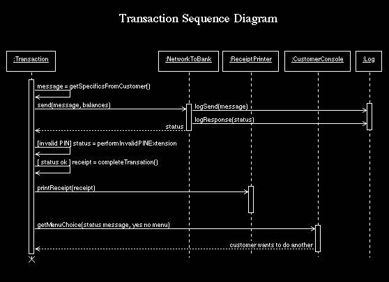
23 Page 23
24 User KeyPad ATM Machine 1: Insert card 2: Validate card 3: Please insert Valid card 4: Enter Pin Number 5: Pin Number 6: Validate Pin Number 7: Wrong Pin Enter Currect One 8: Select Transaction Type 9: Enter The Amount To WithDraw 10: Amount In Digits 11: Check Balance 12: Can't WithDraw Ur Balance is Low 13: Do U want Receipt 14: Yes / No 15: Please Collect Ur Money & Receipt 16: Do U want Continue Yes / No 17: No 18: Thanks You For Using Our ATM Service Page 24


25 5. COLLABORATION DIAGRAM FOR ATM Page 25

26 Page 26
27 6. STATE DIAGRAM Statechart diagram is used to model dynamic nature of a system. They define different states of an object during its lifetime. And these states are changed by events. So Statechart diagrams are useful to model reactive systems. Reactive systems can be defined as a system that responds to external or internal events. Statechart diagram describes the flow of control from one state to another state. States are defined as a condition in which an object exists and it changes when some event is triggered. So the most important purpose of Statechart diagram is to model life time of an object from creation to termination. Statechart diagrams are also used for forward and reverse engineering of a system. But the main purpose is to model reactive system. Following are the main purposes of using Statechart diagrams: 1. To model dynamic aspect of a system. 2. To model life time of a reactive system. 3. To describe different states of an object during its life time. 4. Define a state machine to model states of an object. Contents Simply state and composite states Transitions, including events and actions Common use They are use to model the dynamic aspects of a system. Event ordered behavior of any kind of objects, to model reactive objects. Page 27


28 STATE CHART DIAGRAM OF ATM Page 28

29 7.ACTIVITY DIAGRAM Activity diagram is basically a flow chart to represent the flow form one activity to another. The activity can be described as an operation of the system. So the control flow is drawn from one operation to another. This flow can be sequential, branched or concurrent. Activity diagrams deals with all type of flow by using elements like fork, join etc. Contents Fork Initial/Final State, Activity, Fork & Join, Branch, Swimlanes A fork represents the splitting of a single flow of control into two or more concurrentflow of control. A fork may have one incoming transition and two or more outgoing transitions, each of which represents an independent flow of control. Below fork the activities associated with each of these path continues in parallel. Page 29
30 Join A join represents the synchronization of two or more concurrent flows of control. A join may have two or more incoming transition and one outgoing transition. Above the join the activities associated with each of these paths continues in parallel. Branching A branch specifies alternate paths takes based on some Boolean expression Branch is represented by diamond Branch may have one incoming transition and two or more outgoing one on each outgoing transition, you place a Boolean expression shouldn t overlap but they should cover all possibilities. Swimlane: Swimlanes are useful when we model workflows of business processes to partition the activity states on an activity diagram into groups. Each group representing the business organization responsible for those activities,these groups are called Swimlanes. Page 30
31 Activity Diagram for ATM 8. COMPONENT DIAGRAM Component diagrams are used to model physical aspects of a system. Now the question is what are these physical aspects? Physical aspects are the elements like executables, libraries, files, documents etc which resides in a node. So component diagrams are used to visualize the Page 31
32 organization and relationships among components in a system. These diagrams are also used to make executable systems. Purpose: Component diagrams can be described as a static implementation view of a system. Static implementation represents the organization of the components at a particular moment. A single component diagram cannot represent the entire system but a collection of diagrams are used to represent the whole. Before drawing a component diagram the following artifacts are to be identified clearly: Files used in the system. Libraries and other artifacts relevant to the application. Relationships among the artifacts. Now after identifying the artifacts the following points needs to be followed: Use a meaningful name to identify the component for which the diagram is to be drawn. Prepare a mental layout before producing using tools. Use notes for clarifying important points. Now the usage of component diagrams can be described as: 1. Model the components of a system. 2. Model database schema. 3. Model executables of an application. 4. Model system s source code. Contents Components, Interfaces, Relationships Page 32


33 Component Diagram for ATM Deployment diagram for ATM system Page 33
Using UML Part Two Behavioral Modeling Diagrams
 UML Tutorials Using UML Part Two Behavioral Modeling Diagrams by Sparx Systems All material Sparx Systems 2007 Sparx Systems 2007 Page 1 Trademarks Object Management Group, OMG, Unified Modeling Language,
ATM Case Study Part 1
 ATM Case Study Part 1 A requirements document specifies the purpose of the ATM system and what it must do. Requirements Document A local bank intends to install a new automated teller machine (ATM) to
Chapter 19. Activity Diagrams
 Use a sequence diagram if you want to emphasize the time ordering of messages. Use a collaboration diagram if you want to emphasize the organization of the objects involved in the interaction. Lay out
Types of UML Diagram. UML Diagrams 140703-OOAD. Computer Engineering Sem -IV
 140703-OOAD Computer Engineering Sem -IV Introduction to UML - UML Unified Modeling Language diagram is designed to let developers and customers view a software system from a different perspective and
CPS122 Lecture: State and Activity Diagrams in UML
 CPS122 Lecture: State and Activity Diagrams in UML Objectives: last revised February 14, 2012 1. To show how to create and read State Diagrams 2. To introduce UML Activity Diagrams Materials: 1. Demonstration
Questions? Assignment. Techniques for Gathering Requirements. Gathering and Analysing Requirements
 Questions? Assignment Why is proper project management important? What is goal of domain analysis? What is the difference between functional and non- functional requirements? Why is it important for requirements
How To Develop Software
 Software Engineering Prof. N.L. Sarda Computer Science & Engineering Indian Institute of Technology, Bombay Lecture-4 Overview of Phases (Part - II) We studied the problem definition phase, with which
Case Study: ATM machine I. Amalia Foka CEID - University of Patras Object Oriented Programming II (C++) Fall 2010-2011
 Fall 2010-2011") Case Study: ATM machine I Amalia Foka CEID - University of Patras Object Oriented Programming II (C++) Fall 2010-2011 Requirements Document An ATM allows users to perform basic financial transactions view
Case Study: ATM machine I Amalia Foka CEID - University of Patras Object Oriented Programming II (C++) Fall 2010-2011 Requirements Document An ATM allows users to perform basic financial transactions view
Model Simulation in Rational Software Architect: Business Process Simulation
 Model Simulation in Rational Software Architect: Business Process Simulation Mattias Mohlin Senior Software Architect IBM The BPMN (Business Process Model and Notation) is the industry standard notation
Introduction. UML = Unified Modeling Language It is a standardized visual modeling language.
 UML 1 Introduction UML = Unified Modeling Language It is a standardized visual modeling language. Primarily intended for modeling software systems. Also used for business modeling. UML evolved from earlier
BPMN Business Process Modelling Notation
 BPMN Business Process Modelling Notation Knut Hinkelmann This chapter is based on the BPMN Tutorial of Stephen A. White and the book White, S.A., Miers, D. (2008) BPMN - Modeling and Reference Guide. Future
BPMN Business Process Modeling Notation
 BPMN (BPMN) is a graphical notation that describes the logic of steps in a business process. This notation has been especially designed to coordinate the sequence of processes and messages that flow between
Process Modeling Notations and Workflow Patterns
 Process Modeling Notations and Workflow Patterns Stephen A. White, IBM Corp., United States ABSTRACT The research work of Wil van der Aalst, Arthur ter Hofstede, Bartek Kiepuszewski, and Alistair Barros
Process Modeling using BPMN 2.0
 Process Modeling using BPMN 2.0 This chapter provides a brief overview of Business Process Modeling Notation (BPMN) concepts with particular emphasis on the BPMN 2.0 additions. In addition, it describes
Sequence Diagrams. Massimo Felici. Massimo Felici Sequence Diagrams c 2004 2011
 Sequence Diagrams Massimo Felici What are Sequence Diagrams? Sequence Diagrams are interaction diagrams that detail how operations are carried out Interaction diagrams model important runtime interactions
Interaction Diagrams. Use Cases and Actors INTERACTION MODELING
 Karlstad University Department of Information Systems Adapted for a textbook by Blaha M. and Rumbaugh J. Object Oriented Modeling and Design Pearson Prentice Hall, 2005 INTERACTION MODELING Remigijus GUSTAS
ATM Case Study OBJECTIVES. 2005 Pearson Education, Inc. All rights reserved. 2005 Pearson Education, Inc. All rights reserved.
 1 ATM Case Study 2 OBJECTIVES.. 3 2 Requirements 2.9 (Optional) Software Engineering Case Study: Examining the Requirements Document 4 Object-oriented design (OOD) process using UML Chapters 3 to 8, 10
A UML Introduction Tutorial
 A UML Introduction Tutorial 1/27/08 9:55 PM A UML Introduction Tutorial In this tutorial you will learn about the fundamentals of object oriented modelling, the Unified Modelling Language and the software
Requirements engineering
 Learning Unit 2 Requirements engineering Contents Introduction............................................... 21 2.1 Important concepts........................................ 21 2.1.1 Stakeholders and
Applying 4+1 View Architecture with UML 2. White Paper
 Applying 4+1 View Architecture with UML 2 White Paper Copyright 2007 FCGSS, all rights reserved. www.fcgss.com Introduction Unified Modeling Language (UML) has been available since 1997, and UML 2 was
Quick Guide Business Process Modeling Notation (BPMN)
") Quick Guide Business Process Modeling Notation (BPMN) IDM Technical Team January 2007 Quick Guide: BPMN 2 of 14 The scope of this document is to provide a quick guide to the concepts and usage of the Business
Quick Guide Business Process Modeling Notation (BPMN) IDM Technical Team January 2007 Quick Guide: BPMN 2 of 14 The scope of this document is to provide a quick guide to the concepts and usage of the Business
i. Node Y Represented by a block or part. SysML::Block,
 OMG SysML Requirements Traceability (informative) This document has been published as OMG document ptc/07-03-09 so it can be referenced by Annex E of the OMG SysML specification. This document describes
Umbrello UML Modeller Handbook
 2 Contents 1 Introduction 7 2 UML Basics 8 2.1 About UML......................................... 8 2.2 UML Elements........................................ 9 2.2.1 Use Case Diagram.................................
Chap 1. Introduction to Software Architecture
 Chap 1. Introduction to Software Architecture 1. Introduction 2. IEEE Recommended Practice for Architecture Modeling 3. Architecture Description Language: the UML 4. The Rational Unified Process (RUP)
System Modeling / Class Diagra Diagr m a Week 6
 System Modeling / Class Diagram Week 6 System modeling Agenda (Lecture) Agenda (Lab) Create CRC cards for your group project Create a system level (analysis level) class diagram (Lab Assignment #6) for
Managing Variability in Software Architectures 1 Felix Bachmann*
 Managing Variability in Software Architectures Felix Bachmann* Carnegie Bosch Institute Carnegie Mellon University Pittsburgh, Pa 523, USA fb@sei.cmu.edu Len Bass Software Engineering Institute Carnegie
Diagramming Techniques:
 1 Diagramming Techniques: FC,UML,PERT,CPM,EPC,STAFFWARE,... Eindhoven University of Technology Faculty of Technology Management Department of Information and Technology P.O. Box 513 5600 MB Eindhoven The
Business Process Modelling. CA4 Business Process Modelling 1
 Business Process Modelling CA4 Business Process Modelling 1 Historical View of BP Modelling Work Process Flow (early to mid 1900s) + Frank Gilbreth & his 'Flow Process Charts' (= flowcharts) + First structured
Object Oriented Programming. Risk Management
 Section V: Object Oriented Programming Risk Management In theory, there is no difference between theory and practice. But, in practice, there is. - Jan van de Snepscheut 427 Chapter 21: Unified Modeling
[1] http://en.wikipedia.org/wiki/first-mover_advantage [2] http://www.acunote.com
![[1] http://en.wikipedia.org/wiki/first-mover_advantage [2] http://www.acunote.com](/thumbs/24/2883514.jpg "[1] http://en.wikipedia.org/wiki/first-mover_advantage [2] http://www.acunote.com") -Gene Sher Software Development Processes: Those in engineering and science will sooner or later either be members of teams solving some large project, or be managing teams solving some large project.
-Gene Sher Software Development Processes: Those in engineering and science will sooner or later either be members of teams solving some large project, or be managing teams solving some large project.
Software Project Management and UML
 Software Project Management and UML Ali Bigdelou Computer Aided Medical Procedures (CAMP), Technische Universität München, Germany Outline Intro to Software Project Management Project Requirements Specification
Introduction to BPMN
 Stephen A. White, IBM Corporation Abstract This paper is intended to provide a high-level overview and introduction to the Business Process Modeling Notation (BPMN). The context and general uses for BPMN
Compliance and Requirement Traceability for SysML v.1.0a
 1. Introduction: Compliance and Traceability for SysML v.1.0a This document provides a formal statement of compliance and associated requirement traceability for the SysML v. 1.0 alpha specification, which
Using Use Cases on Agile Projects
 Using Use Cases on Agile Projects Ivar Jacobson with Ian Spence Agenda What are agile teams looking for? Cards, conversations, and confirmations Knowing what to do and when it s done Being agile with use
Using UML Part One Structural Modeling Diagrams
 UML Tutorials Using UML Part One Structural Modeling Diagrams by Sparx Systems All material Sparx Systems 2007 Sparx Systems 2007 Page 1 Trademarks Object Management Group, OMG, Unified Modeling Language,
Communications Software Engineering Design Model
 Communications Software Engineering Design Model Wolfgang Emmerich 1 Lecture Overview Relationship between analysis and design Stages of design Impact of implementation environment Definition of sequence
Contents. Introduction and System Engineering 1. Introduction 2. Software Process and Methodology 16. System Engineering 53
 Preface xvi Part I Introduction and System Engineering 1 Chapter 1 Introduction 2 1.1 What Is Software Engineering? 2 1.2 Why Software Engineering? 3 1.3 Software Life-Cycle Activities 4 1.3.1 Software
Object Oriented Design
 Object Oriented Design Kenneth M. Anderson Lecture 20 CSCI 5828: Foundations of Software Engineering OO Design 1 Object-Oriented Design Traditional procedural systems separate data and procedures, and
BPMN by example. Bizagi Suite. Copyright 2014 Bizagi
 BPMN by example Bizagi Suite Recruitment and Selection 1 Table of Contents Scope... 2 BPMN 2.0 Business Process Modeling Notation... 2 Why Is It Important To Model With Bpmn?... 2 Introduction to BPMN...
Writing Use Case Scenarios for Model Driven Development
 Writing Use Case Scenarios for Model Driven Development This guide outlines how to use Enterprise Architect to rapidly build Use Cases and increase your productivity through Model Driven Development. Use
WebSphere Business Modeler
 Discovering the Value of SOA WebSphere Process Integration WebSphere Business Modeler Workshop SOA on your terms and our expertise Soudabeh Javadi Consulting Technical Sales Support WebSphere Process Integration
Using Rational Rose to Create Object-Oriented Diagrams
 Using Rational Rose to Create Object-Oriented Diagrams This is a brief overview to get students started in using Rational Rose to quickly create object-oriented models and diagrams. It is not by any means
Automated Modeling of Legacy Systems Using the UML
 Automated Modeling of Legacy Systems Using the UML by Pan-Wei Ng Software Engineering Specialist Rational Software Singapore Poor documentation is one of the major challenges of supporting legacy systems;
Requirements Document for the Banking System. Lecture # 40
 Requirements Document for the Banking System Lecture # 40 Requirements Document The requirements document is a formal document used to communicate the requirements to customers, engineers and managers
Use-Case Analysis. ! What is it? ! From where did it come? ! Now part of UML
 Use-Case Analysis Use-Case Analysis! What is it?! An informal, user-friendly, technique useful for functional requirements analysis and specification! From where did it come?! Ivar Jacobson, a Swedish
Introduction to Systems Analysis and Design
 Introduction to Systems Analysis and Design What is a System? A system is a set of interrelated components that function together to achieve a common goal. The components of a system are called subsystems.
Decomposition into Parts. Software Engineering, Lecture 4. Data and Function Cohesion. Allocation of Functions and Data. Component Interfaces
 Software Engineering, Lecture 4 Decomposition into suitable parts Cross cutting concerns Design patterns I will also give an example scenario that you are supposed to analyse and make synthesis from The
The Business Process Model
 The Business Process Model by Sparx Systems All material Sparx Systems 2007 Sparx Systems 2007 Page: 1 Table of Contents INTRODUCTION...3 BUSINESS PROCESS MODELING NOTATION (BPMN)...4 FLOW ELEMENTS...4
Scenario-based Requirements Engineering and User-Interface Design
 Scenario-based Requirements Engineering and User-Interface Institut für Computertechnik ICT Institute of Computer Technology Hermann Kaindl Vienna University of Technology, ICT Austria kaindl@ict.tuwien.ac.at
Chapter 10 Practical Database Design Methodology and Use of UML Diagrams
 Chapter 10 Practical Database Design Methodology and Use of UML Diagrams Copyright 2011 Pearson Education, Inc. Publishing as Pearson Addison-Wesley Chapter 10 Outline The Role of Information Systems in
Modeling Guidelines Manual
 Modeling Guidelines Manual [Insert company name here] July 2014 Author: John Doe john.doe@johnydoe.com Page 1 of 22 Table of Contents 1. Introduction... 3 2. Business Process Management (BPM)... 4 2.1.
Communication Diagrams
 Communication Diagrams Massimo Felici Realizing Use cases in the Design Model 1 Slide 1: Realizing Use cases in the Design Model Use-case driven design is a key theme in a variety of software processes
COSC 3351 Software Design. Recap for the first quiz. Edgar Gabriel. Spring 2008. For the 1 st Quiz
 COSC 3351 Software Design Recap for the first quiz Spring 2008 For the 1 st Quiz Three large topic areas: UML syntax and diagrams Software architectural styles Object oriented design principles A couple
Case studies: Outline. Requirement Engineering. Case Study: Automated Banking System. UML and Case Studies ITNP090 - Object Oriented Software Design
 I. Automated Banking System Case studies: Outline Requirements Engineering: OO and incremental software development 1. case study: withdraw money a. use cases b. identifying class/object (class diagram)
Announcements. SE 1: Software Requirements Specification and Analysis. Review: Use Case Descriptions
 Announcements SE 1: Software Requirements Specification and Analysis Lecture 4: Basic Notations Nancy Day, Davor Svetinović http://www.student.cs.uwaterloo.ca/ cs445/winter2006 uw.cs.cs445 Send your group
UML-based Test Generation and Execution
 UML-based Test Generation and Execution Jean Hartmann, Marlon Vieira, Herb Foster, Axel Ruder Siemens Corporate Research, Inc. 755 College Road East Princeton NJ 08540, USA jeanhartmann@siemens.com ABSTRACT
MTAT.03.231 Business Process Management (BPM) (for Masters of IT) Lecture 2: Introduction to BPMN
 (for Masters of IT) Lecture 2: Introduction to BPMN") MTAT.03.231 Business Process Management (BPM) (for Masters of IT) Lecture 2: Introduction to BPMN Marlon Dumas marlon.dumas ät ut. ee How to engage in BPM? 1. Opportunity assessment 2. Process modelling
MTAT.03.231 Business Process Management (BPM) (for Masters of IT) Lecture 2: Introduction to BPMN Marlon Dumas marlon.dumas ät ut. ee How to engage in BPM? 1. Opportunity assessment 2. Process modelling
Fourth generation techniques (4GT)
") Fourth generation techniques (4GT) The term fourth generation techniques (4GT) encompasses a broad array of software tools that have one thing in common. Each enables the software engineer to specify some
Fourth generation techniques (4GT) The term fourth generation techniques (4GT) encompasses a broad array of software tools that have one thing in common. Each enables the software engineer to specify some
Chapter 3. Technology review. 3.1. Introduction
 Technology review Chapter 3 3.1. Introduction Previous chapter covers detail description about problem domain. In this chapter I will discuss the technologies currently available to solve a problem in
Business Process Modeling Information Systems in Industry (372-1-4207 )
") Business Process Modeling Information Systems in Industry (372-1-4207 ) Arnon Sturm The material of this presentation is adopted from various people including:, Pnina Soffer, Iris Reinhartz-Berger 1 Outline
Business Process Modeling Information Systems in Industry (372-1-4207 ) Arnon Sturm The material of this presentation is adopted from various people including:, Pnina Soffer, Iris Reinhartz-Berger 1 Outline
2 SYSTEM DESCRIPTION TECHNIQUES
 2 SYSTEM DESCRIPTION TECHNIQUES 2.1 INTRODUCTION Graphical representation of any process is always better and more meaningful than its representation in words. Moreover, it is very difficult to arrange
Software testing. Objectives
 Software testing cmsc435-1 Objectives To discuss the distinctions between validation testing and defect testing To describe the principles of system and component testing To describe strategies for generating
UML TUTORIALS THE USE CASE MODEL
 UML TUTORIALS THE USE CASE MODEL www.sparxsystems.com.au Sparx Systems 2004 Page 1/5 describes the proposed functionality of the new system. A Use Case represents a discrete unit of interaction between
Process / Operation Symbols
 Flowchart s and Their Meanings Flowchart s Defined By Nicholas Hebb The following is a basic overview, with descriptions and meanings, of the most common flowchart symbols - also commonly called flowchart
Chapter 10 Practical Database Design Methodology and Use of UML Diagrams
 Chapter 10 Practical Database Design Methodology and Use of UML Diagrams Copyright 2011 Pearson Education, Inc. Publishing as Pearson Addison-Wesley Chapter 10 Outline The Role of Information Systems in
TECH. Requirements. Why are requirements important? The Requirements Process REQUIREMENTS ELICITATION AND ANALYSIS. Requirements vs.
 CH04 Capturing the Requirements Understanding what the customers and users expect the system to do * The Requirements Process * Types of Requirements * Characteristics of Requirements * How to Express
Developing SOA solutions using IBM SOA Foundation
 Developing SOA solutions using IBM SOA Foundation Course materials may not be reproduced in whole or in part without the prior written permission of IBM. 4.0.3 4.0.3 Unit objectives After completing this
Sofware Requirements Engineeing
 Sofware Requirements Engineeing Three main tasks in RE: 1 Elicit find out what the customers really want. Identify stakeholders, their goals and viewpoints. 2 Document write it down (). Understandable
EVALUATION. WA1844 WebSphere Process Server 7.0 Programming Using WebSphere Integration COPY. Developer
 WA1844 WebSphere Process Server 7.0 Programming Using WebSphere Integration Developer Web Age Solutions Inc. USA: 1-877-517-6540 Canada: 1-866-206-4644 Web: http://www.webagesolutions.com Chapter 6 - Introduction
BIS 3106: Business Process Management. Lecture Two: Modelling the Control-flow Perspective
 BIS 3106: Business Process Management Lecture Two: Modelling the Control-flow Perspective Makerere University School of Computing and Informatics Technology Department of Computer Science SEM I 2015/2016
Candle Plant process automation based on ABB 800xA Distributed Control Systems
 Candle Plant process automation based on ABB 800xA Distributed Control Systems Yousef Iskandarani and Karina Nohammer Department of Engineering University of Agder Jon Lilletuns vei 9, 4879 Grimstad Norway
Syllabus M.C.A. Object Oriented Modeling and Design usung UML
 I Syllabus M.C.A. (Semester IV) Object Oriented Modeling and Design usung UML INTRODUCTION An overview - Object basics - Object state and properties, Behavior, Methods, Messages. Object Oriented system
Rapid Development of Modular Dynamic Web Sites using UML
 Rapid Development of Modular Dynamic Web Sites using UML Tim Schattkowsky 1, Marc Lohmann 2 1 Paderborn University, C-LAB, D-33102 Paderborn, Germany tim@c-lab.de 2 Paderborn University, Department of
INTRODUCTION TO BUSINESS PROCESS MODELING NOTATION BPMN 1.2 AND BPMN 2.0
 INTRODUCTION TO BUSINESS PROCESS MODELING NOTATION BPMN 1.2 AND BPMN 2.0 Email: {goliva,gerosa}@ime.usp.br / Twitter: @golivax Agenda 2 Introduction to Business Processes BPMN 1.2 Introduction Elements
Example Use Case Specification:
 Example Use Case Specification: Level 1 Identified Use Case Name: Actor(s): Other Stakeholders: Summary Description: Priority: Risk Level: Status: Withdraw Cash Any Bank Customer (primary) Banking System
JOURNAL OF OBJECT TECHNOLOGY
 JOURNAL OF OBJECT TECHNOLOGY Online at http://www.jot.fm. Published by ETH Zurich, Chair of Software Engineering JOT, 2006 Vol. 5, No. 6, July - August 2006 On Assuring Software Quality and Curbing Software
Masters of Science in Software & Information Systems
 Masters of Science in Software & Information Systems To be developed and delivered in conjunction with Regis University, School for Professional Studies Object Oriented Design Table of Contents January
Object-Oriented Systems Analysis and Design
 Object-Oriented Systems Analysis and Design Noushin Ashrafi Professor of Information System University of Massachusetts-Boston Hessam Ashrafi Software Architect Pearson Education International CONTENTS
UML TUTORIALS THE COMPONENT MODEL
 UML TUTORIALS THE COMPONENT MODEL www.sparxsystems.com.au Sparx Systems 2004 Page 1/5 The component model illustrates the software components that will be used to build the system. These may be built up
In this Lecture you will Learn: Systems Development Methodologies. Why Methodology? Why Methodology?
 In this Lecture you will Learn: Systems Development Methodologies What a systems development methodology is Why methodologies are used The need for different methodologies The main features of one methodology
Business Process Modeling with BPMN. Dr. Darius Šilingas Head of Solutions Department darius.silingas@nomagic.com
 Business Process Modeling with BPMN Dr. Darius Šilingas Head of Solutions Department darius.silingas@nomagic.com No Magic Europe, 2012 About Instructor Dr. Darius Šilingas q Principal Consultant and Head
StarUML Documentation
 StarUML Documentation Release 2.0.0 MKLab June 24, 2016 Contents 1 Basic Concepts 3 1.1 Project.................................................. 3 1.2 Model vs. Diagram............................................
UML Diagram Types. Use Cases do the Following. Use Case Diagram
 UML Diagram Types Dynamic Models activity diagrams statechart diagrams interaction diagrams sequence diagrams collaboration diagrams use case diagrams Structural Models class diagrams object diagrams packages
UML Activities & Actions. Charles ANDRE - UNSA
 UML Activities & Actions Action & Object Nodes Accept inputs, start behaviors, provide outputs Object/Data flow Control flow Send Envoice Invoice Make Payment Accept Payment Invoice1234: Invoice Invoice1234:
USING UML FOR OBJECT-RELATIONAL DATABASE SYSTEMS DEVELOPMENT: A FRAMEWORK
 USING UML FOR OBJECT-RELATIONAL DATABASE SYSTEMS DEVELOPMENT: A FRAMEWORK Ming Wang, California State University, ming.wang@calstatela.edu ABSTRACT Data model of object-relational databases (ORDBs) is
How to Make a Domain Model. Tutorial
 How to Make a Domain Model Tutorial What is a Domain Model? Illustrates meaningful conceptual classes in problem domain Represents real-world concepts, not software components Software-oriented class diagrams
SECTION 2 PROGRAMMING & DEVELOPMENT
 Page 1 SECTION 2 PROGRAMMING & DEVELOPMENT DEVELOPMENT METHODOLOGY THE WATERFALL APPROACH The Waterfall model of software development is a top-down, sequential approach to the design, development, testing
Aspect Oriented Strategy to model the Examination Management Systems
 Aspect Oriented Strategy to model the Examination Management Systems P.Durga 1, S.Jeevitha 2, A.Poomalai 3, Prof.M.Sowmiya 4 and Prof.S.Balamurugan 5 Department of IT, Kalaignar Karunanidhi Institute of
Implementation Workflow
 Implementation Workflow Michael Fourman Introduction Implement the design in terms of components source code, scripts, binaries, executables, etc. Flesh out the architecture Plan system integrations in
Toad for Oracle 8.6 SQL Tuning
 Quick User Guide for Toad for Oracle 8.6 SQL Tuning SQL Tuning Version 6.1.1 SQL Tuning definitively solves SQL bottlenecks through a unique methodology that scans code, without executing programs, to
Instructional Systems Design
 Analysis and Design of Distance Learning Systems: Instructional Systems Design Contents The Purpose of Design Audience of Design documents Phases of Instructional Design Development of initial Content
Process Modelling Notations
 Process Modelling Notations Event-driven Process Chains (EPC) Business Process Modelling Notation (BPMN) Workflow Management Agenda Motivation for BPM EPC BPMN Case Study 1 Why Business Process Modelling
Zen of VISIO 2008. Leona Rubin WebTechNY User Group Date: September, 2008
 Zen of VISIO 2008 Leona Rubin WebTechNY User Group Date: September, 2008 About the speaker Leona Rubin from New York began her career as a Senior Technical Communicator, Information Designer and Management
SignalDraw: GUI Tool For Generating Pulse Sequences
 SignalDraw: GUI Tool For Generating Pulse Sequences Konstantin Berlin Department of Computer Science University of Maryland College Park, MD 20742 kberlin@cs.umd.edu December 9, 2005 Abstract Generating
How To Create A Complex Diagram On A Computer Game
 ENTERPRISE ARCHITECT IMPORT user guide No Magic, Inc. 2013 All material contained herein is considered proprietary information owned by No Magic, Inc. and is not to be shared, copied, or reproduced by
Kirsten Sinclair SyntheSys Systems Engineers
 Kirsten Sinclair SyntheSys Systems Engineers Kirsten Sinclair SyntheSys Systems Engineers Spicing-up IBM s Enterprise Architecture tools with Petri Nets On Today s Menu Appetiser: Background Starter: Use
Database Programming with PL/SQL: Learning Objectives
 Database Programming with PL/SQL: Learning Objectives This course covers PL/SQL, a procedural language extension to SQL. Through an innovative project-based approach, students learn procedural logic constructs
Software Requirements
 Software Engineering Software Requirements Based on Software Engineering, 7 th Edition by Ian Sommerville Objectives To introduce the concepts of user and system requirements To describe functional and
Business Process Redesign and Modelling
 Business Process Redesign and Modelling The Business Process Redesign the Process Handbook the key idea of the Process Handbook approach is that a richly structured online repository about business processes