13. Pipe flow I ( , 6.6)
|
|
|
- Betty Maxwell
- 7 years ago
- Views:
Transcription
1 13. Pipe flow I ( , 6.6) Energy losses in pipe flow Local energy losses Pipes connected in series Exercises: D13, D14, and (D15)
2 PIPE FLOW Flow of water, oil and gas in pipes is of immense importance in civil engineering: Distribution of water from source to consumers (private, municipal, process industries) Transport of waste water and storm water to recipient via treatment plant Transport of oil and gas from source to refineries (oil) or into distribution networks (gas) via pipelines Some data from Sweden: Average water consumption: 330 liters/(person and day) Purchase cost ( Anskaffningsvärde ) for water and waste water pipes: 50 billion SEK Length of all water pipes put together: km
3 TWO FACTORS OF IMPORTANCE IN DESIGN OF PIPES 1) Hydraulic transport capacity of the pipe In a pressurized system the hydraulic transport capacity is a function of the fall of pressure along the pipe. The fall of pressure is caused by energy losses in the pipe: - Energy losses due to friction due to shear stresses along pipe walls - Local losses that arises at pipe bends, valves, enlargements, contractions, etc ) Strength of pipe usually determined on basis of high and low pressures in conjunction with flow changes (closing of valve or pump stop)
4 (total energi) (trycknivå)
5 ENERGY LOSSES IN PIPE FLOW Energy equation: p 1 w γ + z 1 + V 1 g = p wγ + z + V g + h losses h losses = h friction + h local The objective is to determine a relation between energy losses and mean velocity in a pipe: h friction = f(v) and h local = f (V)
6 Energy losses due to friction Calculated using Darcy Weisbach s formula (general friction formula for both laminar and turbulent flow; Eq. 6.1): h L V f = f D g or h f = f 5 D gπ h f energy loss due to friction over a distance, L (m), along the pipe f pipe friction factor[f=f(re, Pipe wall roughness ); Fig Moody diagram, laminar flow f = 64/Re; Re = VD/ν] D Pipediameter (m) V average velocity in the pipe (m/s) Q flowrate in the pipe (m 3 /s) L 16Q
7 D13 Calculate the smallest reliable flowrate that can be pumped through this pipeline. D = 5 mm, f = 0.00, L = x 45 m, Vertical distances are 7.5 m and 15 m respectively. Assume atmospheric pressure kpa. 1
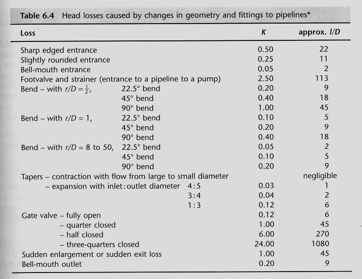
8 Local energy losses Minor head losses in pipelines occur at pipe bends, valves ( ventiler ), enlargement and contraction of pipe sections, junctions ( knutpunkter ) etc. In long pipelines these local head losses are often minor in comparison with energy losses due to friction and may be neglected. In short pipes, however, they may be greater than frictional losses and should be accounted for. Local losses usually result from abrupt changes in velocity leading to eddy formation which extract energy from the mean flow. Increase of velocity is associated with small head (energy) losses and decrease of velocity with large head losses
9 Local energy losses (cont.) Usually it is possible to write local energy losses in pipe flow using the following formula: h local = K local V g h local = local energy loss K local = local loss coefficient (different for different types of losses) V /(g) = kinetic energy (velocity head)
10 LOCAL ENERGY LOSS - ENLARGEMENT : Loss coefficient, K L, for sudden enlargement (V=V 1 ): D /D K L
11 ENERGY LOSS FOR OUTFLOW IN RESERVOIR VVR 10 Fluid Mechanics
12 LOCAL ENERGY LOSS - CONTRACTION Loss coefficient for sudden contraction (Franzini and Finnemore, 1997, V = V ): D /D K L
13 Head loss coefficient for different types of pipe entrances
14 VVR 10 Fluid VVR 10 Fluid Mechanics Head loss at smooth pipe bends
15 Loss coefficients at right angle bends
16
17 Pipe systems pipes in series Solution Energy equation Total head, H = Δz = h f1 + h f + Σh local Continuity equation Q = Q 1 = Q
18 D14 Water is flowing. Calculate the gage reading when V300 is.4 m/s. (NOTE El. = elevation) 1
19 D15 Calculate magnitude and direction of manometer reading.
Pressure drop in pipes...
 Pressure drop in pipes... PRESSURE DROP CALCULATIONS Pressure drop or head loss, occurs in all piping systems because of elevation changes, turbulence caused by abrupt changes in direction, and friction
Chapter 8: Flow in Pipes
 Objectives 1. Have a deeper understanding of laminar and turbulent flow in pipes and the analysis of fully developed flow 2. Calculate the major and minor losses associated with pipe flow in piping networks
Experiment 3 Pipe Friction
 EML 316L Experiment 3 Pipe Friction Laboratory Manual Mechanical and Materials Engineering Department College of Engineering FLORIDA INTERNATIONAL UNIVERSITY Nomenclature Symbol Description Unit A cross-sectional
ME 305 Fluid Mechanics I. Part 8 Viscous Flow in Pipes and Ducts
 ME 305 Fluid Mechanics I Part 8 Viscous Flow in Pipes and Ducts These presentations are prepared by Dr. Cüneyt Sert Mechanical Engineering Department Middle East Technical University Ankara, Turkey csert@metu.edu.tr
Hydraulic losses in pipes
 Hydraulic losses in pipes Henryk Kudela Contents 1 Viscous flows in pipes 1 1.1 Moody Chart.................................... 2 1.2 Types of Fluid Flow Problems........................... 5 1.3 Minor
Pipe Flow-Friction Factor Calculations with Excel
 Pipe Flow-Friction Factor Calculations with Excel Course No: C03-022 Credit: 3 PDH Harlan H. Bengtson, PhD, P.E. Continuing Education and Development, Inc. 9 Greyridge Farm Court Stony Point, NY 10980
FLUID FLOW Introduction General Description
 FLUID FLOW Introduction Fluid flow is an important part of many processes, including transporting materials from one point to another, mixing of materials, and chemical reactions. In this experiment, you
4.What is the appropriate dimensionless parameter to use in comparing flow types? YOUR ANSWER: The Reynolds Number, Re.
 CHAPTER 08 1. What is most likely to be the main driving force in pipe flow? A. Gravity B. A pressure gradient C. Vacuum 2.What is a general description of the flow rate in laminar flow? A. Small B. Large
Open Channel Flow. M. Siavashi. School of Mechanical Engineering Iran University of Science and Technology
 M. Siavashi School of Mechanical Engineering Iran University of Science and Technology W ebpage: webpages.iust.ac.ir/msiavashi Email: msiavashi@iust.ac.ir Landline: +98 21 77240391 Fall 2013 Introduction
Practice Problems on Pumps. Answer(s): Q 2 = 1850 gpm H 2 = 41.7 ft W = 24.1 hp. C. Wassgren, Purdue University Page 1 of 16 Last Updated: 2010 Oct 29
: Q 2 = 1850 gpm H 2 = 41.7 ft W = 24.1 hp. C. Wassgren, Purdue University Page 1 of 16 Last Updated: 2010 Oct 29") _02 A centrifugal with a 12 in. diameter impeller requires a power input of 60 hp when the flowrate is 3200 gpm against a 60 ft head. The impeller is changed to one with a 10 in. diameter. Determine the
_02 A centrifugal with a 12 in. diameter impeller requires a power input of 60 hp when the flowrate is 3200 gpm against a 60 ft head. The impeller is changed to one with a 10 in. diameter. Determine the
CEE 370 Fall 2015. Laboratory #3 Open Channel Flow
 CEE 70 Fall 015 Laboratory # Open Channel Flow Objective: The objective of this experiment is to measure the flow of fluid through open channels using a V-notch weir and a hydraulic jump. Introduction:
Head Loss in Pipe Flow ME 123: Mechanical Engineering Laboratory II: Fluids
 Head Loss in Pipe Flow ME 123: Mechanical Engineering Laboratory II: Fluids Dr. J. M. Meyers Dr. D. G. Fletcher Dr. Y. Dubief 1. Introduction Last lab you investigated flow loss in a pipe due to the roughness
Water Supply. Simulation of Water Distribution Networks. Mohammad N. Almasri. Optimal Design of Water Distribution Networks Mohammad N.
 Water Supply Simulation of Water Distribution Networks The Use of EPANET Mohammad N. Almasri 1 Introduction This presentation focuses on two issues: The simulation of water distribution networks (WDNs)
CE 6303 MECHANICS OF FLUIDS L T P C QUESTION BANK PART - A
 CE 6303 MECHANICS OF FLUIDS L T P C QUESTION BANK 3 0 0 3 UNIT I FLUID PROPERTIES AND FLUID STATICS PART - A 1. Define fluid and fluid mechanics. 2. Define real and ideal fluids. 3. Define mass density
Chapter 13 OPEN-CHANNEL FLOW
 Fluid Mechanics: Fundamentals and Applications, 2nd Edition Yunus A. Cengel, John M. Cimbala McGraw-Hill, 2010 Lecture slides by Mehmet Kanoglu Copyright The McGraw-Hill Companies, Inc. Permission required
When the fluid velocity is zero, called the hydrostatic condition, the pressure variation is due only to the weight of the fluid.
 Fluid Statics When the fluid velocity is zero, called the hydrostatic condition, the pressure variation is due only to the weight of the fluid. Consider a small wedge of fluid at rest of size Δx, Δz, Δs
LECTURE 1: Review of pipe flow: Darcy-Weisbach, Manning, Hazen-Williams equations, Moody diagram
 LECTURE 1: Review of pipe flow: Darcy-Weisbach, Manning, Hazen-Williams equations, Moody diagram 1.1. Important Definitions Pressure Pipe Flow: Refers to full water flow in closed conduits of circular
OUTCOME 3 TUTORIAL 5 DIMENSIONAL ANALYSIS
 Unit 41: Fluid Mechanics Unit code: T/601/1445 QCF Level: 4 Credit value: 15 OUTCOME 3 TUTORIAL 5 DIMENSIONAL ANALYSIS 3 Be able to determine the behavioural characteristics and parameters of real fluid
Experimentation and Computational Fluid Dynamics Modelling of Roughness Effects in Flexible Pipelines
 Experimentation and Computational Fluid Dynamics Modelling of Roughness Effects in Flexible Pipelines Sophie Yin Jeremy Leggoe School of Mechanical and Chemical Engineering Daniel Teng Paul Pickering CEED
Open channel flow Basic principle
 Open channel flow Basic principle INTRODUCTION Flow in rivers, irrigation canals, drainage ditches and aqueducts are some examples for open channel flow. These flows occur with a free surface and the pressure
Special Linings for unusual service conditions. Please contact ACIPCO.
 Linings Linings Along with technical and metallurgical advancement in piping materials, research on lining requirements for pipe and fittings has resulted in the development of linings to meet many different
Experiment (13): Flow channel
: Flow channel") Introduction: An open channel is a duct in which the liquid flows with a free surface exposed to atmospheric pressure. Along the length of the duct, the pressure at the surface is therefore constant and
Introduction: An open channel is a duct in which the liquid flows with a free surface exposed to atmospheric pressure. Along the length of the duct, the pressure at the surface is therefore constant and
CHAPTER 3 STORM DRAINAGE SYSTEMS
 CHAPTER 3 STORM DRAINAGE SYSTEMS 3.7 Storm Drains 3.7.1 Introduction After the tentative locations of inlets, drain pipes, and outfalls with tail-waters have been determined and the inlets sized, the next
Urban Hydraulics. 2.1 Basic Fluid Mechanics
 Urban Hydraulics Learning objectives: After completing this section, the student should understand basic concepts of fluid flow and how to analyze conduit flows and free surface flows. They should be able
Darcy Friction Factor Formulae in Turbulent Pipe Flow
 Darcy Friction Factor Formulae in Turbulent Pipe Flow Jukka Kiijärvi Lunowa Fluid Mechanics Paper 110727 July 29, 2011 Abstract The Darcy riction actor in turbulent pipe low must be solved rom the Colebrook
Chapter 10. Open- Channel Flow
 Updated: Sept 3 2013 Created by Dr. İsmail HALTAŞ Created: Sept 3 2013 Chapter 10 Open- Channel Flow based on Fundamentals of Fluid Mechanics 6th EdiAon By Munson 2009* *some of the Figures and Tables
Practice Problems on Boundary Layers. Answer(s): D = 107 N D = 152 N. C. Wassgren, Purdue University Page 1 of 17 Last Updated: 2010 Nov 22
: D = 107 N D = 152 N. C. Wassgren, Purdue University Page 1 of 17 Last Updated: 2010 Nov 22") BL_01 A thin flat plate 55 by 110 cm is immersed in a 6 m/s stream of SAE 10 oil at 20 C. Compute the total skin friction drag if the stream is parallel to (a) the long side and (b) the short side. D =
BL_01 A thin flat plate 55 by 110 cm is immersed in a 6 m/s stream of SAE 10 oil at 20 C. Compute the total skin friction drag if the stream is parallel to (a) the long side and (b) the short side. D =
Contents. Microfluidics - Jens Ducrée Physics: Fluid Dynamics 1
 Contents 1. Introduction 2. Fluids 3. Physics of Microfluidic Systems 4. Microfabrication Technologies 5. Flow Control 6. Micropumps 7. Sensors 8. Ink-Jet Technology 9. Liquid Handling 10.Microarrays 11.Microreactors
Experiment # 3: Pipe Flow
 ME 05 Mechanical Engineering Lab Page ME 05 Mechanical Engineering Laboratory Spring Quarter 00 Experiment # 3: Pipe Flow Objectives: a) Calibrate a pressure transducer and two different flowmeters (paddlewheel
Water hammering in fire fighting installation
 Water hammering in fire fighting installation Forward One of major problems raised in the fire fighting network installed at Pioneer company for pharmaceutical industry /Sulaymania was the high water hammering
Chapter 9. Steady Flow in Open channels
 Chapter 9 Steady Flow in Open channels Objectives Be able to define uniform open channel flow Solve uniform open channel flow using the Manning Equation 9.1 Uniform Flow in Open Channel Open-channel flows
Environment Protection Engineering ENTRANCE LOSS COEFFICIENTS IN PIPE HYDRAULIC SYSTEMS
 Environment Protection Engineering Vol. 37 2011 No. 4 ANDRZEJ KOTOWSKI*, HENRYK SZEWCZYK**, WOJCIECH CIEŻAK* ENTRANCE LOSS COEFFICIENTS IN PIPE HYDRAULIC SYSTEMS The entrance loss coefficients have been
Fluid Dynamics Basics
 Fluid Dynamics Basics Bernoulli s Equation A very important equation in fluid dynamics is the Bernoulli equation. This equation has four variables: velocity ( ), elevation ( ), pressure ( ), and density
Pipe Flow Expert. Verification of Calculation Results
 http://www.pipeflow.com Pipe Flow Expert Fluid Flow and Pressure Loss Calculations Software Verification of Calculation Results Table of Contents Results Data: Systems Solved by Pipe Flow Expert Introduction...
OUTCOME 1 STATIC FLUID SYSTEMS TUTORIAL 1 - HYDROSTATICS
 Unit 41: Fluid Mechanics Unit code: T/601/1445 QCF Level: 4 Credit value: 15 OUTCOME 1 STATIC FLUID SYSTEMS TUTORIAL 1 - HYDROSTATICS 1. Be able to determine the behavioural characteristics and parameters
WATER MEASUREMENT USING TWO INCH (50 mm) DRAIN TESTS
 DRAIN TESTS") GAP.14.1.2.2 A Publication of Global Asset Protection Services LLC WATER MEASUREMENT USING TWO INCH (50 mm) DRAIN TESTS INTRODUCTION A hydrant or other large-volume flow test is necessary for proper water
GAP.14.1.2.2 A Publication of Global Asset Protection Services LLC WATER MEASUREMENT USING TWO INCH (50 mm) DRAIN TESTS INTRODUCTION A hydrant or other large-volume flow test is necessary for proper water
Unit 24: Applications of Pneumatics and Hydraulics
 Unit 24: Applications of Pneumatics and Hydraulics Unit code: J/601/1496 QCF level: 4 Credit value: 15 OUTCOME 2 TUTORIAL 2 HYDRAULIC AND PNEUMATIC CYLINDERS The material needed for outcome 2 is very extensive
FLUID FLOW STREAMLINE LAMINAR FLOW TURBULENT FLOW REYNOLDS NUMBER
 VISUAL PHYSICS School of Physics University of Sydney Australia FLUID FLOW STREAMLINE LAMINAR FLOW TURBULENT FLOW REYNOLDS NUMBER? What type of fluid flow is observed? The above pictures show how the effect
Minor losses include head losses through/past hydrants, couplers, valves,
 Lecture 10 Minor Losses & Pressure Requirements I. Minor Losses Minor (or fitting, or local ) hydraulic losses along pipes can often be estimated as a function of the velocity head of the water within
F f v 1 = c100(10 3 ) m h da 1h 3600 s b =
 m h da 1h 3600 s b =") 14 11. The 2-Mg car has a velocity of v 1 = 100km>h when the v 1 100 km/h driver sees an obstacle in front of the car. It takes 0.75 s for him to react and lock the brakes, causing the car to skid. If
14 11. The 2-Mg car has a velocity of v 1 = 100km>h when the v 1 100 km/h driver sees an obstacle in front of the car. It takes 0.75 s for him to react and lock the brakes, causing the car to skid. If
L r = L m /L p. L r = L p /L m
 NOTE: In the set of lectures 19/20 I defined the length ratio as L r = L m /L p The textbook by Finnermore & Franzini defines it as L r = L p /L m To avoid confusion let's keep the textbook definition,
Aids needed for demonstrations: viscous fluid (water), tubes (pipes), injections, paper, stopwatches, vessels,, weights
, tubes (pipes), injections, paper, stopwatches, vessels,, weights") 1 Viscous and turbulent flow Level: high school (16-17 years) hours (2 hours class teaching, 2 hours practical excercises) Content: 1. Viscous flow 2. Poiseuille s law 3. Passing from laminar to turbulent
1 Viscous and turbulent flow Level: high school (16-17 years) hours (2 hours class teaching, 2 hours practical excercises) Content: 1. Viscous flow 2. Poiseuille s law 3. Passing from laminar to turbulent
Liquid Applied Internal Flow Coatings for Oil Transmission Lines
 Liquid Applied Internal Flow Coatings for Oil Transmission Lines M R McDonnell E Wood Limited United Kingdom This paper will examine more closely the benefits to the Industry by lining Oil Pipelines. Introduction
SECTION 5 - STORM DRAINS
 Drainage Criteria Manual SECTION 5 - STORM DRAINS 5.1.0 GENERAL This The purpose of this section discusses briefly is to consider the hydraulic aspects of storm drains and their appurtenances in a storm
Pacific Pump and Power
 Pacific Pump and Power 91-503 Nukuawa Street Kapolei, Hawaii 96707 Phone: (808) 672-8198 or (800) 975-5112 Fax: (866) 424-0953 Email: sales@pacificpumpandpower.com Web: www.pacificpumpandpower.com Pumps
Air-side Systems: Air Duct Design
 BBSE3006: Air Conditioning and Refrigeration II http://www.hku.hk/bse/bbse3006/ Air-side Systems: Air Duct Design Dr. Sam C M Hui Department of Mechanical Engineering The University of Hong Kong E-mail:
Pumps: Convert mechanical energy (often developed from electrical source) into hydraulic energy (position, pressure and kinetic energy).
 into hydraulic energy (position, pressure and kinetic energy).") HYDRAULIC MACHINES Used to convert between hydraulic and mechanical energies. Pumps: Convert mechanical energy (often developed from electrical source) into hydraulic energy (position, pressure and kinetic
HYDRAULIC MACHINES Used to convert between hydraulic and mechanical energies. Pumps: Convert mechanical energy (often developed from electrical source) into hydraulic energy (position, pressure and kinetic
PAGE 2. Figure 1: Difference between PWL ins and SPL 1m
 PAGE 1 Pipe noise J.H. Granneman and R.P.M. Jansen, Peutz Consulting Engineers, The Netherlands, emphasise the need for an adequate pipe noise control procedure, with reference to the design phase, insulation
HYDRAULIC ANALYSIS OF PIPE LINED WITH MADISON S 100% SOLIDS STRUCTURAL POLYURETHANE COATINGS
 HYDRAULIC ANALYSIS OF PIPE LINED WITH MADISON S 100% SOLIDS STRUCTURAL POLYURETHANE COATINGS Shiwei William Guan, Ph.D. Vice President, R&D and International Business Madison Chemical Industries Inc. 490
The Viscosity of Fluids
 Experiment #11 The Viscosity of Fluids References: 1. Your first year physics textbook. 2. D. Tabor, Gases, Liquids and Solids: and Other States of Matter (Cambridge Press, 1991). 3. J.R. Van Wazer et
M6a: Open Channel Flow (Manning s Equation, Partially Flowing Pipes, and Specific Energy)
") M6a: Open Channel Flow (, Partially Flowing Pipes, and Specific Energy) Steady Non-Uniform Flow in an Open Channel Robert Pitt University of Alabama and Shirley Clark Penn State - Harrisburg Continuity
M6a: Open Channel Flow (, Partially Flowing Pipes, and Specific Energy) Steady Non-Uniform Flow in an Open Channel Robert Pitt University of Alabama and Shirley Clark Penn State - Harrisburg Continuity
A drop forms when liquid is forced out of a small tube. The shape of the drop is determined by a balance of pressure, gravity, and surface tension
 A drop forms when liquid is forced out of a small tube. The shape of the drop is determined by a balance of pressure, gravity, and surface tension forces. 2 Objectives Have a working knowledge of the basic
du u U 0 U dy y b 0 b
 BASIC CONCEPTS/DEFINITIONS OF FLUID MECHANICS (by Marios M. Fyrillas) 1. Density (πυκνότητα) Symbol: 3 Units of measure: kg / m Equation: m ( m mass, V volume) V. Pressure (πίεση) Alternative definition:
Chapter 2. Derivation of the Equations of Open Channel Flow. 2.1 General Considerations
 Chapter 2. Derivation of the Equations of Open Channel Flow 2.1 General Considerations Of interest is water flowing in a channel with a free surface, which is usually referred to as open channel flow.
MATLAB AS A PROTOTYPING TOOL FOR HYDRONIC NETWORKS BALANCING
 MATLAB AS A PROTOTYPING TOOL FOR HYDRONIC NETWORKS BALANCING J. Pekař, P. Trnka, V. Havlena* Abstract The objective of this note is to describe the prototyping stage of development of a system that is
What is the most obvious difference between pipe flow and open channel flow????????????? (in terms of flow conditions and energy situation)
") OPEN CHANNEL FLOW 1 3 Question What is the most obvious difference between pipe flow and open channel flow????????????? (in terms of flow conditions and energy situation) Typical open channel shapes Figure
OPEN CHANNEL FLOW 1 3 Question What is the most obvious difference between pipe flow and open channel flow????????????? (in terms of flow conditions and energy situation) Typical open channel shapes Figure
Theory, Application, and Sizing of Air Valves
 Theory, Application, and Sizing of Air Valves VAL-MATIC VALVE AND MANUFACTURING CORP. 905 RIVERSIDE DRIVE, ELMHURST, IL 60126 TEL. (630) 941-7600 FAX. (630) 941-8042 www.valmatic.com 1 THEORY, APPLICATION,
HEAT TRANSFER ENHANCEMENT AND FRICTION FACTOR ANALYSIS IN TUBE USING CONICAL SPRING INSERT
 HEAT TRANSFER ENHANCEMENT AND FRICTION FACTOR ANALYSIS IN TUBE USING CONICAL SPRING INSERT Rahul M. Gupta 1, Bhushan C. Bissa 2 1 Research Scholar, Department of Mechanical Engineering, Shri Ramdeobaba
VAL-MATIC VALVE AND MANUFACTURING CORP. 905 RIVERSIDE DRIVE, ELMHURST, IL 60126 TEL. (630) 941-7600 FAX.
 941-7600 FAX.") Cavitation in Valves VAL-MATIC VALVE AND MANUFACTURING CORP. 905 RIVERSIDE DRIVE, ELMHURST, IL 60126 TEL. (630) 941-7600 FAX. (630) 941-8042 www.valmatic.com CAVITATION IN VALVES INTRODUCTION Cavitation
Cavitation in Valves VAL-MATIC VALVE AND MANUFACTURING CORP. 905 RIVERSIDE DRIVE, ELMHURST, IL 60126 TEL. (630) 941-7600 FAX. (630) 941-8042 www.valmatic.com CAVITATION IN VALVES INTRODUCTION Cavitation
Lecture 24 Flumes & Channel Transitions. I. General Characteristics of Flumes. Flumes are often used:
 Lecture 24 Flumes & Channel Transitions I. General Characteristics of Flumes Flumes are often used: 1. Along contours of steep slopes where minimal excavation is desired 2. On flat terrain where it is
C B A T 3 T 2 T 1. 1. What is the magnitude of the force T 1? A) 37.5 N B) 75.0 N C) 113 N D) 157 N E) 192 N
 37.5 N B) 75.0 N C) 113 N D) 157 N E) 192 N") Three boxes are connected by massless strings and are resting on a frictionless table. Each box has a mass of 15 kg, and the tension T 1 in the right string is accelerating the boxes to the right at a
Three boxes are connected by massless strings and are resting on a frictionless table. Each box has a mass of 15 kg, and the tension T 1 in the right string is accelerating the boxes to the right at a
Design and Pressure Loss Reduction in the Hydrogen Flow Heat Exchanger with Tube Bundles
 Design and Pressure Loss Reduction in the Hydrogen Flow Heat Exchanger with Tube Bundles By Ahmad, Ph.D. asleiti@mail.ucf.edu College of Engineering and Computer Science University of Central Florida Orlando,
Selection and Determination of Tubing and Production Casing Sizes
 CHAPTER 3 Selection and Determination of Tubing and Production Casing Sizes OUTLINE 3.1 Overview 3.2 Overview of Nodal Analysis 3.3 Selection and Determination of Tubing and Production Casing Sizes for
Piping Hydraulic Line Design and Sizing Software KLM Technology Group
 Piping Hydraulic Line Design and Sizing Software KLM Technology Group Practical Engineering Guidelines for Processing Plant Solutions #03-12 Block Aronia, Jalan Sri Perkasa 2 Taman Tampoi Utama 81200 Johor
International Journal of Heat and Mass Transfer
 International Journal of Heat and Mass Transfer 57 (2013) 190 201 Contents lists available at SciVerse ScienceDirect International Journal of Heat and Mass Transfer journal homepage: www.elsevier.com/locate/ijhmt
Module 9: Basics of Pumps and Hydraulics Instructor Guide
 Module 9: Basics of Pumps and Hydraulics Instructor Guide Activities for Unit 1 Basic Hydraulics Activity 1.1: Convert 45 psi to feet of head. 45 psis x 1 ft. = 103.8 ft 0.433 psi Activity 1.2: Determine
Appendix 4-C. Open Channel Theory
 4-C-1 Appendix 4-C Open Channel Theory 4-C-2 Appendix 4.C - Table of Contents 4.C.1 Open Channel Flow Theory 4-C-3 4.C.2 Concepts 4-C-3 4.C.2.1 Specific Energy 4-C-3 4.C.2.2 Velocity Distribution Coefficient
Improved fluid control by proper non-newtonian flow modeling
 Tekna Flow Assurance 2015, Larvik Improved fluid control by proper non-newtonian flow modeling Stein Tore Johansen, SINTEF Sjur Mo, SINTEF A general wall friction model for a non-newtonian fluid has been
A moving piston boundary condition including gap flow in OpenFOAM
 A piston boundary condition including gap flow in OpenFOAM CLEMENS FRIES Johannes Kepler University IMH Altenbergerstrasse 69, 44 Linz AUSTRIA clemens.fries@jku.at BERNHARD MANHARTSGRUBER Johannes Kepler
TEMPERATURE, CONCENTRATION, AND PUMPING EFFECTS ON PAM VISCOSITY
 TEMPERATURE, CONCENTRATION, AND PUMPING EFFECTS ON PAM VISCOSITY D. L. Bjorneberg ABSTRACT. As polyacrylamide (PAM) use in irrigated agriculture increases, new methods are being sought to accurately and
CHAPTER 2 HYDRAULICS OF SEWERS
 CHAPTER 2 HYDRAULICS OF SEWERS SANITARY SEWERS The hydraulic design procedure for sewers requires: 1. Determination of Sewer System Type 2. Determination of Design Flow 3. Selection of Pipe Size 4. Determination
Investigations of a Long-Distance 1000 MW Heat Transport System with APROS Simulation Software
 th International Conference on Structural Mechanics in Reactor Technology (SMiRT ) Espoo, Finland, August 9-4, 9 SMiRT -Division 3, Paper 56 Investigations of a Long-Distance MW Heat Transport System with
The Viscosity of Fluids
 Experiment #11 The Viscosity of Fluids References: 1. Your first year physics textbook. 2. D. Tabor, Gases, Liquids and Solids: and Other States of Matter (Cambridge Press, 1991). 3. J.R. Van Wazer et
XI / PHYSICS FLUIDS IN MOTION 11/PA
 Viscosity It is the property of a liquid due to which it flows in the form of layers and each layer opposes the motion of its adjacent layer. Cause of viscosity Consider two neighboring liquid layers A
Department of Chemical Engineering, National Institute of Technology, Tiruchirappalli 620 015, Tamil Nadu, India
 Experimental Thermal and Fluid Science 32 (2007) 92 97 www.elsevier.com/locate/etfs Studies on heat transfer and friction factor characteristics of laminar flow through a circular tube fitted with right
Pipe Sizes For Water Distribution System Design
 Appendix D Pipe Sizes For Water Distribution System Design D-. This appendix contains information to help determine pipe sizes when designing a water distribution system. Use Table D- and Tables D- through
FLUID MECHANICS. TUTORIAL No.7 FLUID FORCES. When you have completed this tutorial you should be able to. Solve forces due to pressure difference.
 FLUID MECHANICS TUTORIAL No.7 FLUID FORCES When you have completed this tutorial you should be able to Solve forces due to pressure difference. Solve problems due to momentum changes. Solve problems involving
Pipe Flow Experiments
 Pipe Flow Experiments Group: Day: Week: Library Card Number of Your Group Members -1- University of Warwick School of Engineering ESA7 laboratory Exercises Section I Theoretical Preparation 1. Introduction
Residual Chlorine Decay Simulation in Water Distribution System
 The 7 th International Symposium on Water Supply Technology, Yokohama 2006, November 22-24, 2008, Yokohama, Japan Residual Chlorine Decay Simulation in Water Distribution System Toru Nagatani (Osaka Municipal
A basic introduction to steam
 A basic introduction to steam FOR HOT, COLD, MOIST AND DRY, FOUR CHAMPIONS FIERCE. STRIVE HERE FOR MASTERY Milton 1666 Steam Wonderful Steam Very high heat content Recyclable Clean, non toxic Biodegradable
Pipe flow with friction losses solutions using HP and TI calculators By Gilberto E. Urroz, October 2005
 Pipe low with riction losses solutions using HP and TI calculators By Gilberto E. Urroz, October 005 1. arcy-weisbach Equation and riction actor The basic equation governing riction losses in a pipeline
138.255 Section 4 Page 2. Flow in Pipes
 Flow in Pipes 138.255 Section 4 Page 2 Flow in Pipes 1.0 INTRODUCTION In this module we are focusing on the fundamental principles of headloss and we learn how to use headloss charts to estimate the headloss
AgoraLink Agora for Life Science Technologies Linköpings Universitet Kurs i Fysiologisk mätteknik Biofluidflöden
 AgoraLink Agora for Life Science Technologies Linköpings Universitet Kurs i Fysiologisk mätteknik Biofluidflöden Fysiologisk mätteknik Anatomy of the heart The complex myocardium structure right ventricle
pressure inside the valve just before the final release of air. in pipeline systems resulting from 2p 1 p a m C D A o
 BY SRINIVASA LINGIREDDY, DON J. WOOD, AND NAFTALI ZLOZOWER It is a common practice to locate air valves at high elevations along water transmission mains. Improper sizing of an air valve could lead to
INTRODUCTION TO FLUID MECHANICS
 INTRODUCTION TO FLUID MECHANICS SIXTH EDITION ROBERT W. FOX Purdue University ALAN T. MCDONALD Purdue University PHILIP J. PRITCHARD Manhattan College JOHN WILEY & SONS, INC. CONTENTS CHAPTER 1 INTRODUCTION
FLOW CONDITIONER DESIGN FOR IMPROVING OPEN CHANNEL FLOW MEASUREMENT ACCURACY FROM A SONTEK ARGONAUT-SW
 FLOW CONDITIONER DESIGN FOR IMPROVING OPEN CHANNEL FLOW MEASUREMENT ACCURACY FROM A SONTEK ARGONAUT-SW Daniel J. Howes, P.E. 1 Charles M. Burt, Ph.D., P.E. 2 Brett F. Sanders, Ph.D. 3 ABSTRACT Acoustic
check valve slam A methodology for predicting
 BY JOHN V. BALLUN A methodology for predicting check valve slam USING A METHODOLOGY DEVELOPED BY EXTENSIVE TESTING, DESIGNERS CAN MATCH THE DYNAMICS OF A PUMPING SYSTEM WITH THE NONSLAMMING CHARACTERISTICS
CO 2 41.2 MPa (abs) 20 C
 20 C") comp_02 A CO 2 cartridge is used to propel a small rocket cart. Compressed CO 2, stored at a pressure of 41.2 MPa (abs) and a temperature of 20 C, is expanded through a smoothly contoured converging nozzle
comp_02 A CO 2 cartridge is used to propel a small rocket cart. Compressed CO 2, stored at a pressure of 41.2 MPa (abs) and a temperature of 20 C, is expanded through a smoothly contoured converging nozzle
Engine Heat Transfer. Engine Heat Transfer
 Engine Heat Transfer 1. Impact of heat transfer on engine operation 2. Heat transfer environment 3. Energy flow in an engine 4. Engine heat transfer Fundamentals Spark-ignition engine heat transfer Diesel
CE 642 HYDRAULICS. Dr. Emre Can
 CE 642 HYDRAULICS Dr. Emre Can 1 HYDRAULICS Tentative Course Outline Introduction Pipe Flow Open Channel Flows Uniform Flow Non-Uniform Flow Local Changes in Water Levels Channel Controls Sedimentation
Introduction to Water Pipe Sizing
 ONTARIO PLUMBING INSPECTORS ASSOCIATION INC. In the public service since 1920 Introduction to Understanding the Many Methods to Size Water Pipe Presented by: Rainier Bratsch-Blundel, CPSI Plumbing Professor
For Water to Move a driving force is needed
 RECALL FIRST CLASS: Q K Head Difference Area Distance between Heads Q 0.01 cm 0.19 m 6cm 0.75cm 1 liter 86400sec 1.17 liter ~ 1 liter sec 0.63 m 1000cm 3 day day day constant head 0.4 m 0.1 m FINE SAND
OPEN-CHANNEL FLOW. Free surface. P atm
 OPEN-CHANNEL FLOW Open-channel flow is a flow of liquid (basically water) in a conduit with a free surface. That is a surface on which pressure is equal to local atmospheric pressure. P atm Free surface
Swissmetro travels at high speeds through a tunnel at low pressure. It will therefore undergo friction that can be due to:
 I. OBJECTIVE OF THE EXPERIMENT. Swissmetro travels at high speeds through a tunnel at low pressure. It will therefore undergo friction that can be due to: 1) Viscosity of gas (cf. "Viscosity of gas" experiment)
PRESSURE DROP ANALYSIS OF INLET PIPE WITH REDUCER AND WITHOUT REDUCER USING CFD ANALYSIS
 International Journal of Mechanical Engineering (IJME) ISSN(P): 2319-2240; ISSN(E): 2319-2259 Vol. 4, Issue 3, Apr - May 2015, 85-92 IASET PRESSURE DROP ANALYSIS OF INLET PIPE WITH REDUCER AND WITHOUT
Open Channel Flow 2F-2. A. Introduction. B. Definitions. Design Manual Chapter 2 - Stormwater 2F - Open Channel Flow
 Design Manual Chapter 2 - Stormwater 2F - Open Channel Flow 2F-2 Open Channel Flow A. Introduction The beginning of any channel design or modification is to understand the hydraulics of the stream. The
p atmospheric Statics : Pressure Hydrostatic Pressure: linear change in pressure with depth Measure depth, h, from free surface Pressure Head p gh
 IVE1400: n Introduction to Fluid Mechanics Statics : Pressure : Statics r P Sleigh: P..Sleigh@leeds.ac.uk r J Noakes:.J.Noakes@leeds.ac.uk January 008 Module web site: www.efm.leeds.ac.uk/ive/fluidslevel1