DRILLED SHAFTS. Section 465 of Standard Specifications
|
|
|
- Julianna Baker
- 7 years ago
- Views:
Transcription

1 DRILLED SHAFTS Section 465 of Standard Specifications
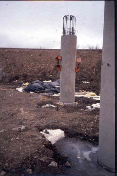
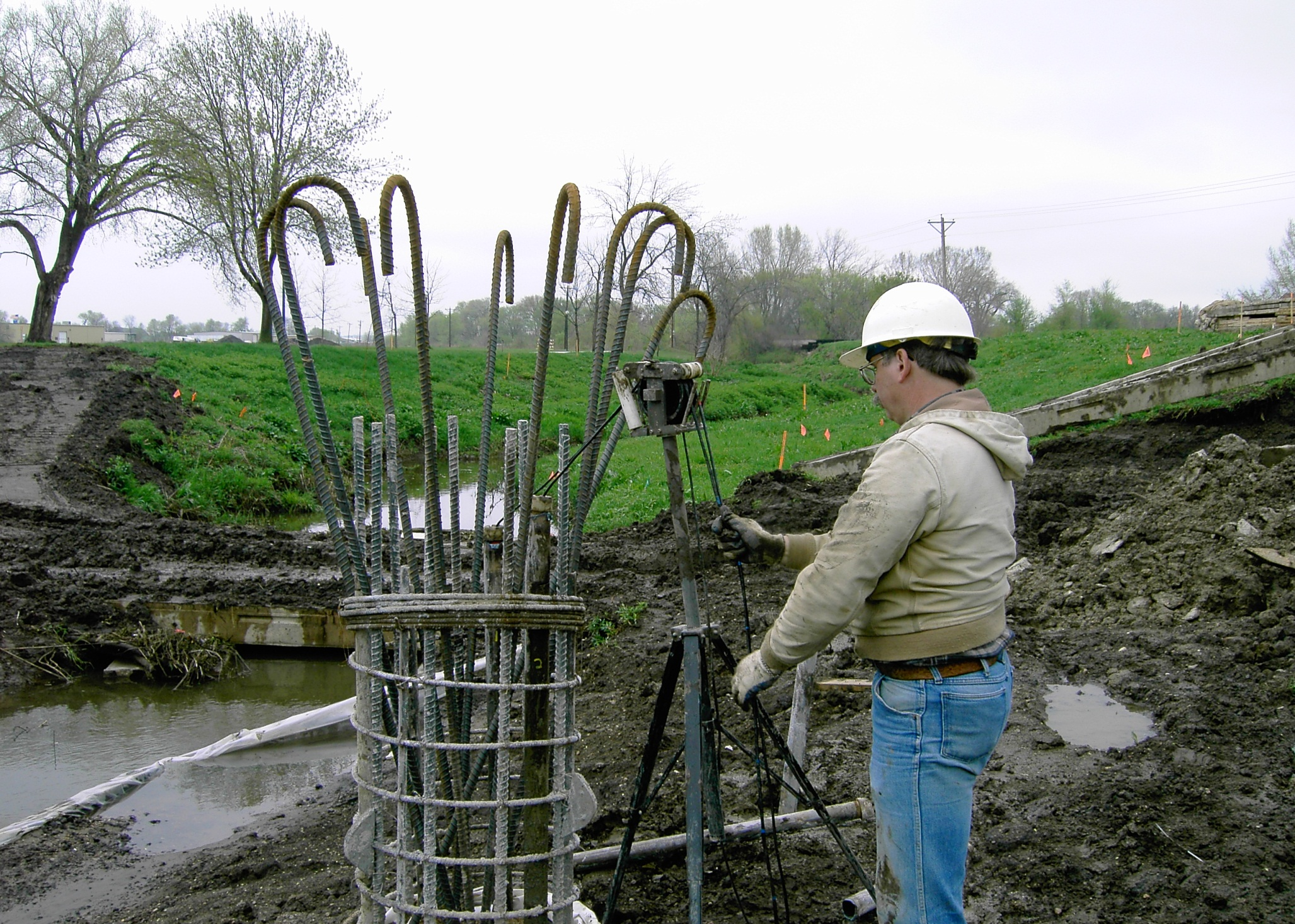
2 What is a Drilled Shaft? Type of substructure foundation. A cylindrical shaft excavated into the ground and then filled with resteel & concrete. Supports loads primarily through skin friction between the concrete and the adjacent soil. End bearing generally not considered. Typical sizes: 30 to 72 in diameter and can extend 50 or more into the ground.
3 What is a Drilled Shaft? Drilled shafts require rigorous inspection. Initial plan review is a must. Should read Section 465 of Standard Specs to clearly understand different types of shaft construction. Need to become familiar with procedures in the specs in event problems are encountered.
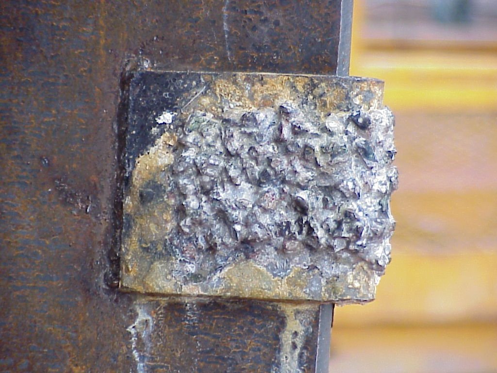
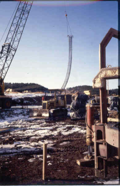
4 Casing Most drilled shafts require a steel casing to be used to facilitate the shaft excavation. The casing is a steel plate rolled and welded to form a large diameter pipe. Casings are placed either before, during or after excavation. Casings are large enough in diameter to permit the drilling auger to pass through them. They should have teeth on the bottom to allow anchoring of the casing into the desired soil formation.

5
6
7 3 Basic Methods of Construction Dry Construction Method Temporary Casing Method Permanent Casing Method Sometimes a combination of the above types of drilled shaft construction methods is used.
8 Preparing for Construction: Prior to Construction the Contractor needs to address 3 items, required by specification. They are: -1. Concrete Mix Design. -2. Drilled Shaft Installation Plan. -3. Drilled Shaft Preconstruction Meeting.
9 Drilled Shaft Concrete Mix Design Contractor must submit a concrete design mix along with materials, including water reducer, to Central Materials Lab at least 40 days prior to construction, for approval. The materials are used by the Lab to verify the Contractor s proposed mix design.
10 Concrete Mix Requirements 28 Day Compressive Strength = 4500 psi Slump Range: 6 to 8 for free fall or tremie method 7 to 9 for concrete pumped through a tremie. In addition, slump shall be maintained above 4 for 4 hours after batching (set retarder). Entrained Air Content of 5% to 7 1/2% Max. Water/Cement Ratio for Design of Mix = 0.44 (Each established mix design will have a maximum water/cement ratio) Slump achieved by use of water reducer. Superplasticizers are NOT allowed. Minimum Cement Content of 780 lbs/yd 3
11 Drilled Shaft Installation Plan Contractor must submit a Detailed drilled shaft installation plan 30 days prior to drilled shaft construction.
12 Equipment List Cranes Drill Augers Pilot Bits Bailing Buckets Cleanout Equipment Water Pumps Tremies Concrete Pumps Concrete Chutes Steel Casing Diameter Wall Thickness
13 Construction Sequence and Methods Sequence of Shaft Construction Elevations of Proposed Work Berms or Platforms Contractor is required to verify site conditions prior to installation plan submittal. How Casing is to Be Installed Method(s) of Excavation
14 Method of Cleaning Out Excavation Details of Resteel Centering Devices Method of Lifting & Supporting Resteel Cage Method(s) of Concrete Placement
15 Pre-Drilled Shaft Meeting Pre-Drilled Shaft Meeting is Mandatory 5 Working Days Prior to Construction of Drilled Shafts.
16 Representatives of the Following are Required to Attend: Bridge Contractor Drilling Sub-Contractor Concrete Supplier Area Office Office of Bridge Design and/or Foundations
17 Purpose Drilled shaft construction can be complex. There are many unknowns. Successful drilled shaft construction depends on everyone involved being fully aware of what each parties responsibilities are. Meeting is used to review step-by-step the procedures and construction methods used. Possible problem scenarios are reviewed & corrective construction procedures are discussed.
18 Drilled Shaft Excavation: Dry Construction Method Drill the shaft through relatively stiff, stable soil formations in which ground water infiltration is not a problem. Not typically used in SD because of this. Clean out bottom of excavation. Set the resteel cage in proper position. Place concrete.
19 When Dry Excavations Encounter Caving or Water Bearing Soils: Contractor should immediately stop drilling The hole should immediately be filled with water to a point above the groundwater elevation. A positive 10 foot head of water should be maintained above the groundwater elevation if possible.
20 Temporary Casing Method -Can be used when shafts are drilled through a layer of granular material, before hitting bedrock, causing side wall caving, shaft squeeze or water infiltration. -The Temporary Casing Method is used when: Excavations, begun by the Dry Construction Method, encounter caving or water bearing soils, or when Specified on the plans.
21 Temp. Casing Method When the Temporary Casing Method is Specified on the Plans: The steel casing is drilled or pushed through the unstable soils prior to the start of excavation. All other procedures are the same as previously discussed.
22 Temp. Casing Method A cleanout bucket is used to clean the bottom of the excavation. The resteel cage is placed in the proper location. Concrete is placed. The casing is extracted during concrete placement.
23 Permanent Casing Method A steel casing is drilled or pushed through the unstable material prior to start of excavation. The drilled shaft is excavated through the steel casing. If water is encountered, a positive head of water is required just the same as was discussed for the Temp. Casing Method
24 Permanent Casing Method The steel casing is left in place. It may sometimes be required to remove portions of the permanent casing after the concrete has attained strength. A cutoff saw, or other approved methods, are required for removal of the casing. Torch-cutting is NOT allowed (unless used before concrete placement)
25 A Combination of These Methods May Be Used The foundation conditions may be such that a casing is required through unstable soil, but the casing is able to be seated into the underlying foundation material such that water infiltration is stopped. This results in a casing being used through the unstable material, but the dry construction method is utilized for the remainder of the drilled shaft.
26 Drilled Shaft Inspection Preliminary Inspection Prior to Drilling
27 Inspection Equipment Plans and Specifications Rod and Level 100 ft. Weighted Tape Mirror Carpenter s Level
28 Location of Drilled Shafts Verify Location of Stakes Check by more than one method Check or Set Offset Stakes Set Temporary Bench Mark May be able to establish elevation of one or more of the offset stakes.
29 Casing Check and Record Casing Dimensions Diameter Length Roundness Make Sure Casing Length has been Adjusted for Work Berms, Etc.
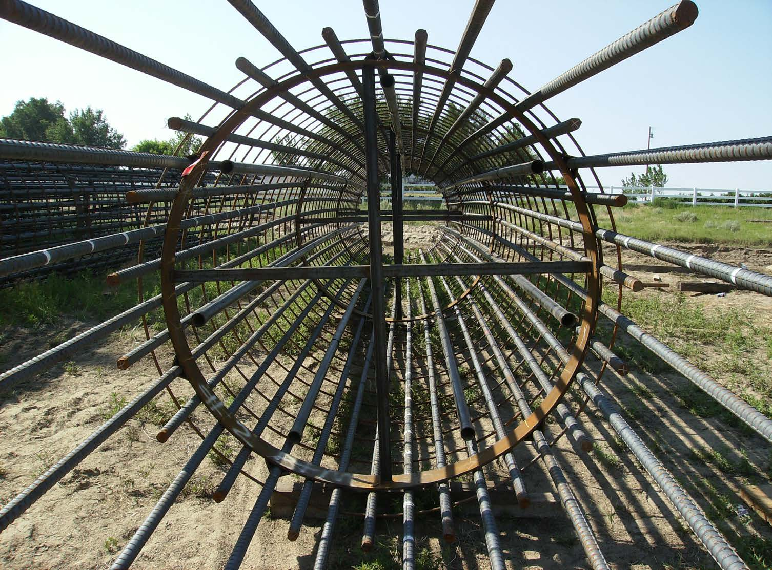
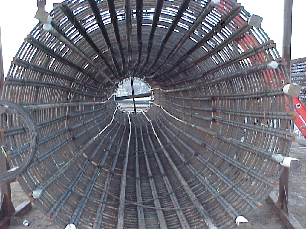
30 Resteel Cage Check Resteel Cage for: Proper Number, Size, and Grade of Bars Proper Diameter and Pitch of Spirals or Hoops Proper Splice Lengths Adequate Approved Centralizers CSL Tubes Correct Spacing and Length Length Adequate to Allow for Splice at Construction Joint
31

32
33 Contractor s Equipment Verify that all Equipment Listed in the Drilled Shaft Installation Plan is on the Site and is in Good Working Condition.
34 Mandatory Equipment Tremie (Even if concrete is to be pumped) T-Bar Cleanout Bucket of proper size Pilot Bit Water Pump Weighted Tape
35

36

37
38 Concrete Make Sure Mix Design has been Approved Check Inside of Tremie Pipe to Assure it is Clean To function properly, Tremie Pipe must be smooth inside. If concrete was not properly cleaned on previous use, concrete will not flow.
39 Drilled Shaft Inspection Setting Casing
40 Setting of the Casing Specifications Require that Casing be Installed using a T-Bar on the Kelly Bar. Accurately Setting Casing can be Difficult Re-check location and Plumbness often Check to assure that casing didn t become outof-round during installation.
41 If Casing Needs to be Removed and Replaced with a Longer Casing, the Excavation is Backfilled Before the New Casing is Installed Bottom of Casing Should be Screwed into Foundation Material to Attain Watertight Seal if Possible Top of Casing Should be at the Approved Construction Joint Location Typically 1 foot above groundline

42
43
44 Drilled Shaft Inspection Excavation
45 Inspection of Excavation Excavation into Frictional Bedrock Should not be Allowed Unless it can be Reasonably Expected that Excavation and Concrete Placement will be Completed the Same Day 24 Hour Time Limit Begins upon excavation into frictional bedrock Frictional Bedrock Elevation is designated on plans
46 Record Time that Frictional Bedrock Elevation is Reached Re-Check Location, Plumbness and Depth Often During Excavation Measure from offset stakes for location Use Carpenter s Level on kelly bar for plumbness Use weighted tape to check depth A Mirror Should be Used to Periodically Check Sides of Excavation for Caving or Water Infiltration
47 If Caving or Water Infiltration is Encountered the Contractor Should Immediately Flood the Excavation with Water When the Excavation Reaches Plans Depth, The Contractor Must Clean the Bottom of the Excavation with the Cleanout Bucket Use the mirror to inspect the bottom of the excavation if the excavation is dry If the excavation is wet, require continued use of the cleanout bucket.

48
49 Drilled Shaft Inspection Resteel Placement
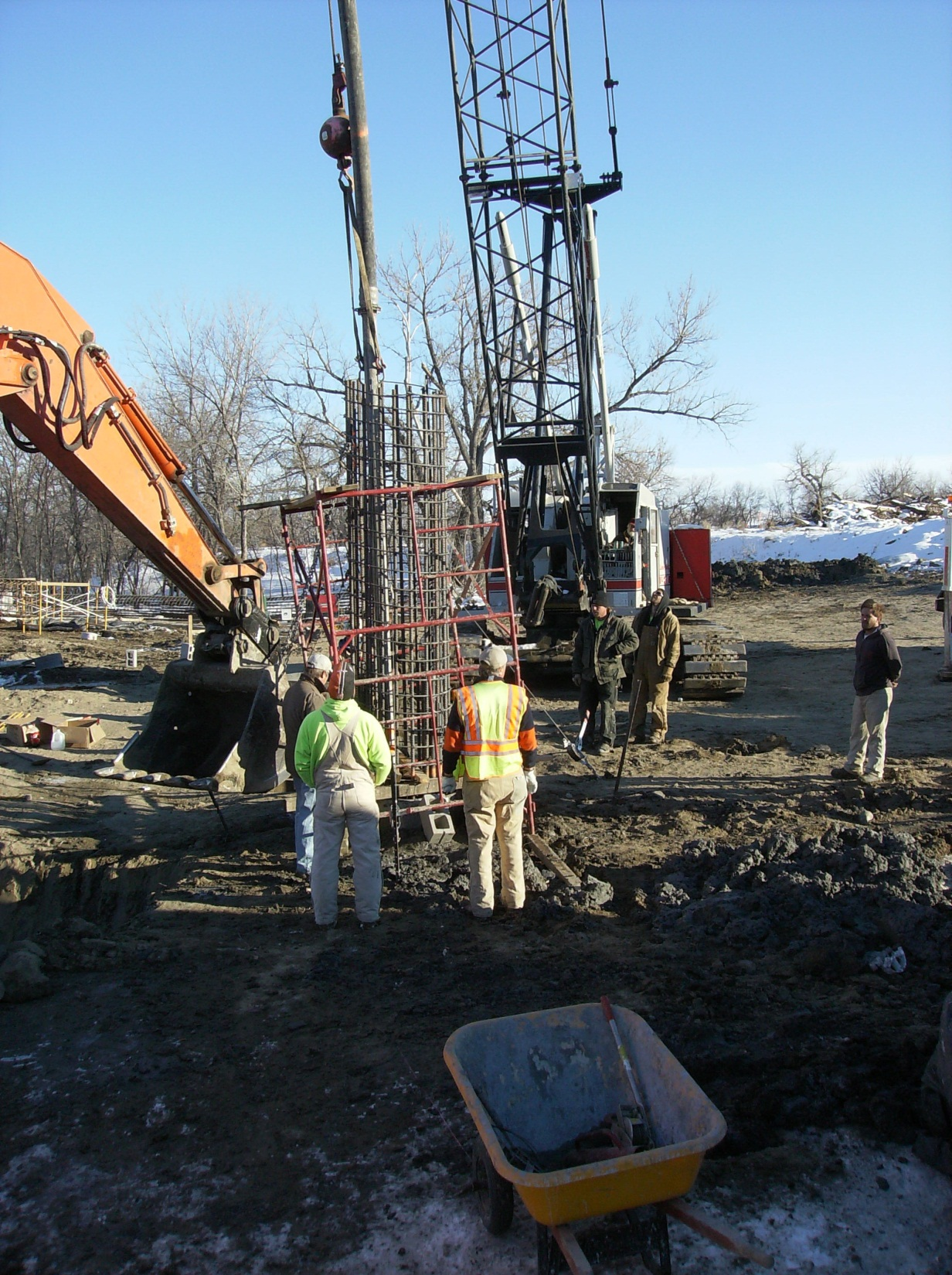
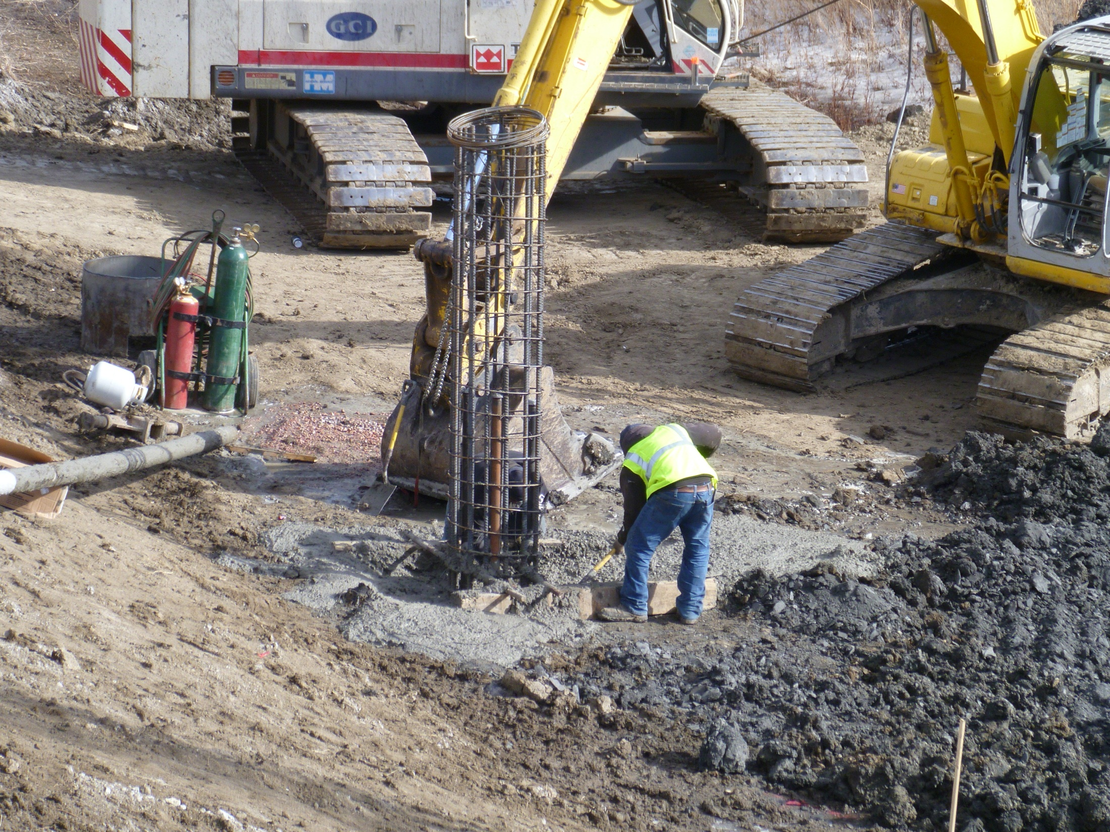
50 Resteel Placement Ensure CSL (Crosshole Sonic Log) tubes are in place before resteel cage is placed Extreme Care Needs to Used in Lifting the Resteel Cage into Place Long Resteel Cages may need to be lifted at more than one point so as not to cause permanent deformation during lifting.
51 Resteel Placement The Resteel Cage Shall be Carefully Lowered into the Excavation If centralizers are knocked off or damaged during resteel placement, the cage shall be raised from the excavation and the centralizers replaced.
52
53
54 Resteel Placement The Resteel Cage Shall be Properly Supported Off of the Bottom of the Excavation Held up by use of crane or other equipment Concrete Donut can be attached to bottom of cage

55
56 Resteel Placement Resteel Cage also Needs to be Tied Down Concrete can FLOAT the resteel cage up during concrete placement Do not tie resteel cage to casing. If resteel cage settles or floats during concrete placement, the watertight seal at the bottom of the casing may be broken.
57 Resteel Placement Check Resteel Extension above Construction Joint to Assure Specified Minimum Splice Length
58 Drilled Shaft Inspection Concrete Placement
59 Concrete Placement in a Dry Excavation Dry Excavation is defined as an excavation in which water accumulates at a rate of no more than 3 inches per hour.
60 The Excavation is to be Dewatered Immediately Prior to Concrete Placement No more than 3 inches of water allowed in bottom of excavation For Drilled Shafts 36 inches in Diameter or Less, Concrete Shall be Placed Through a Drop Tube that Extends to the Bottom of the Excavation Typically, the tremie is used
61 For Drilled Shafts 36 Inches in Diameter or Larger, Concrete May be Placed by the Free- Fall Method A hopper with a drop tube is required to assure that the concrete is dropped down the center of the excavation so as not to fall through any resteel.

62
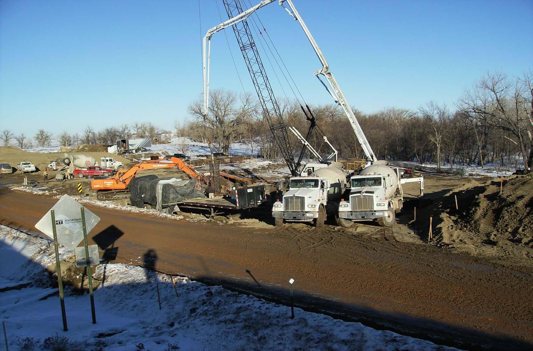
63 Concrete Placement in a Wet Excavation Concrete Must be Placed Underwater Utilizing the Tremie Method This can be achieved either by use of a tremie or a concrete pump
64
65
66 Tremie Method Excavation is Partially or Fully Filled with Water Mark Tremie at Five Foot Intervals The End of the Tremie is Plugged The pig(a foam ball) is placed in the pump and pumped into the shaft to separate the concrete from water in the shaft The pump line needs to be at leaste 4 diameter and be steel for the length of the shaft
67 The Empty Plugged steel pump line is Lowered to the Bottom of the Excavation As the pump is started slowly lift the pump line as the shaft fills making sure the line is imbedded in fresh concrete at least 5 feet
68
69 Process Continues Until all Water has Been Displaced and Enough Concrete has Run Out of the Shaft Such that Only Uncontaminated Concrete Remains. Concrete Placement Should be Performed in One Continuous Operation.
70 Restarting a Tremie If a problem is encountered and Restarting is Required the tremie must be used: The pump line is inadvertently raised such that the minimum 5 foot embedment is not maintained. There is a delay in concrete placement of more than 30 minutes. The pump line plugs.
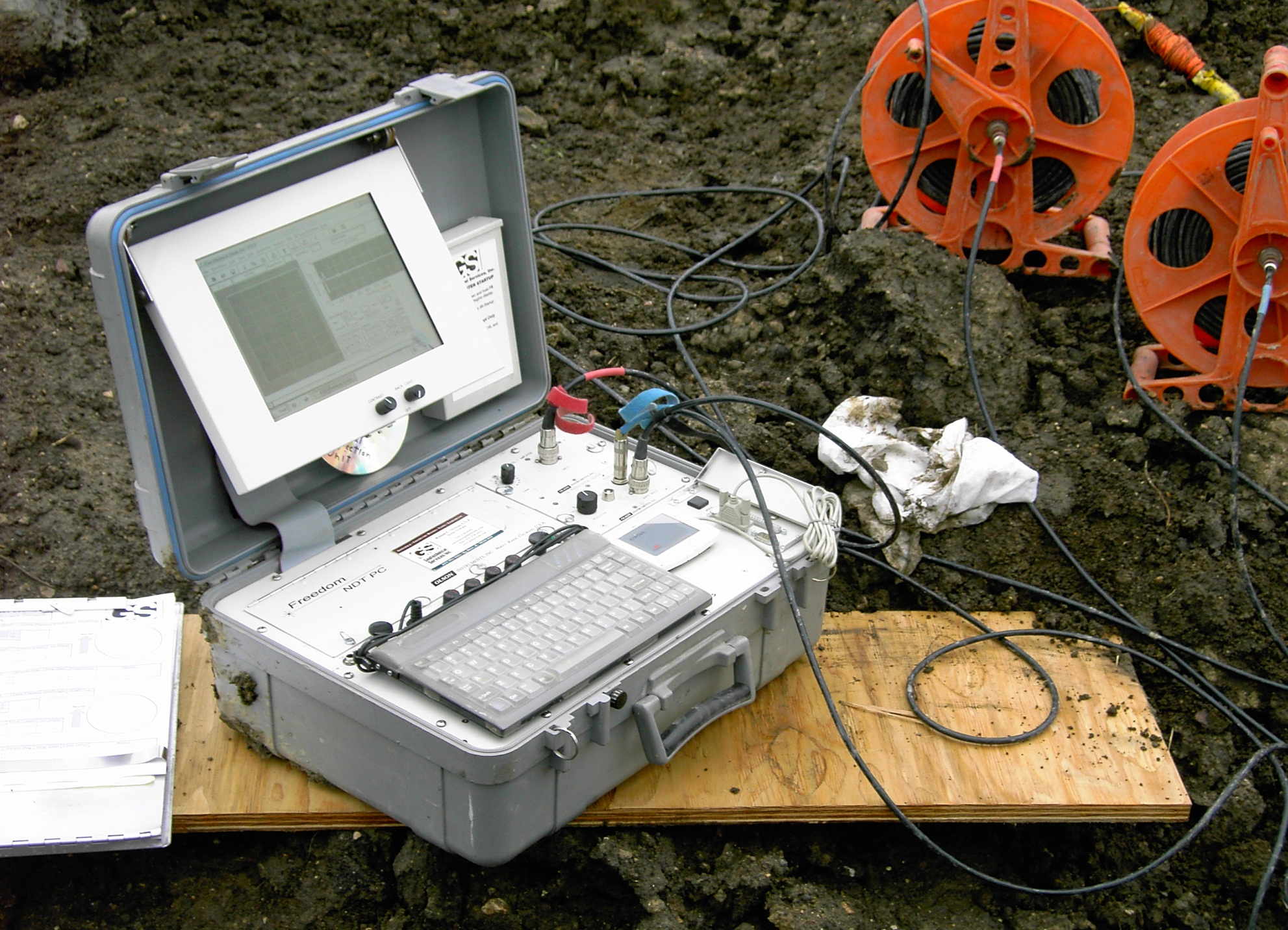
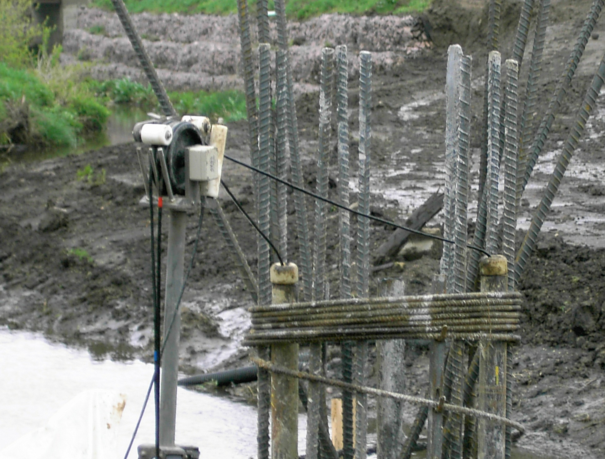
71 Tremie Pipe Requirements Must be Steel Do not allow the use of Aluminum 7.5 Min. Inside Diameter 1/4 Min. Wall Thickness Watertight Joints Gasketed & Bolted Welded Smooth Interior Free of Hardened Concrete
72 Steps to Restart a Tremie Measure and Record Depth to Top of Concrete. Remove pump line Put Plug on End of Tremie Push Empty Plugged Tremie into Concrete to a Minimum Depth of 5 Feet Below Measured Depth Follow Same Procedure as to Begin Placement
73 Work Adjacent to Fresh Concrete Drilling Operations and Free-Fall of Concrete in Adjacent Shafts Can Result in Vibrations Damaging Freshly Placed Concrete This can be monitored by driving a stake into the ground near the fresh concrete and setting a glass of water on top of the stake If ripples appear on the water, operations should be stopped Should not resume these operations for at least 72 hours after concrete placement or until the concrete attains a minimum compressive strength of 1600 psi.
74 Construction Tolerances Horizontal Position 1/12 Shaft Dia. or 3 Inches, Whichever is Less Bottom of Shaft Elevation Plus or Minus 6 Inches Vertical Alignment 1/4 Inch per Foot Depth or 3 Inches, Whichever is less
75 Diameter of Shaft Plus 2 Inches Top of Shaft Elevation Plus or Minus 1 Inch Bottom of shaft shall be relatively flat. Consideration Needs to Be Given to the Fact that the Shafts May be an Extension of the Column Which Require More Stringent Construction Tolerances.
76
77 Drilled Shaft Construction Report (DOT Form 297) Should be Completed for Each Drilled Shaft Constructed All Events of the Drilled Shaft Construction Should be Thoroughly Documented on the Form
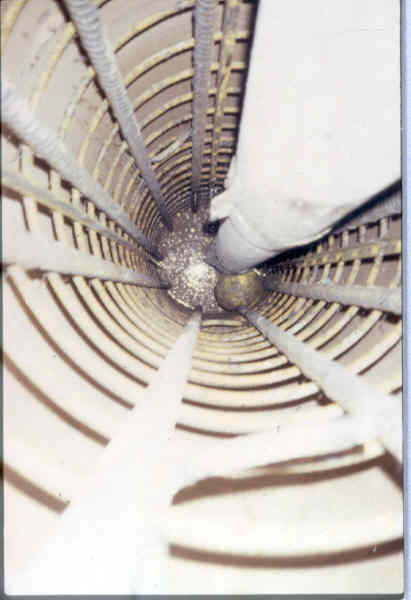
78 CSL Testing Cross Hole Sonic Log (CSL): Test that determines the integrity of the newly placed drilled shaft concrete. Test requires an ultrasonic pulse to pass through the concrete through water filled access tubes. Access tubes are secured to the inside of the rebar cage, and should extend 4 feet above construction joint and be within 3 inches of the bottom of the resteel cage and are cast in the concrete during placement.
79
80
81
82
83 CSL Testing Concrete quality is based on the relationship between pulse velocities and the receiver response energy. High velocities indicate sound quality concrete.
84 CSL Testing Testing will be done by an independent testing organization proposed by the Contractor and approved by the DOT. Acceptance of the drilled shaft will be the decision of the DOT (Foundations Office), based on the results of the CSL reports and other information about the shaft placement.
85 CSL Testing In the case that any shaft is determined to be unacceptable, the Contractor shall submit a plan of remedial action for approval. All costs to perform this remedial action will be at no cost to the State.
86 CSL Testing CSL testing will be used on all single column bents or when drilled shaft construction is suspect. If drilled shaft construction goes well, no CSL testing will be required. After final acceptance of a shaft, the access tubes shall be de-watered, cut off at construction joint and grouted full according to the plans. Any CSL questions?
87
SUPPLEMENTAL TECHNICAL SPECIFICATIONS BI-DIRECTIONAL STATIC LOAD TESTING OF DRILLED SHAFTS
 July 14, 2015 1.0 GENERAL BI-DIRECTIONAL STATIC LOAD TESTING OF DRILLED SHAFTS This work shall consist of furnishing all materials, equipment, labor, and incidentals necessary for conducting bi-directional
SECTION 411 DRILLED PIERS
 Section Payment will be made under: Pay Item Foundation Excavation Foundation Excavation for Bent No. at Station Foundation Excavation for End Bent No. at Station Pay Unit Cubic Yard Lump Sum Lump Sum
Tremie Concrete CM 420 CM 420 CM 420 CM 420. Temporary Structures. Tremie Concrete
 Tremie Concrete Underwater concrete plays an important role in the construction of offshore structures. It may be used to tie together various elements in composite action (i.e., to tie piling to the footing).
High Strain Dynamic Load Testing of Drilled Shafts
 Supplemental Technical Specification for High Strain Dynamic Load Testing of Drilled Shafts SCDOT Designation: SC-M-712 (9/15) September 3, 2015 1.0 GENERAL This work shall consist of performing high-strain
SAMPLE GUIDE SPECIFICATIONS FOR OSTERBERG CELL LOAD TESTING OF DEEP FOUNDATIONS
 Page 1 of 9 SAMPLE GUIDE SPECIFICATIONS FOR OSTERBERG CELL LOAD TESTING OF DEEP FOUNDATIONS 1. GENERAL REQUIREMENTS 1. Description of Work: This work consists of furnishing all materials, equipment and
ITEM #0702770 OSTERBERG CELL LOAD TESTING OF DRILLED SHAFT
 ITEM #0702770 OSTERBERG CELL LOAD TESTING OF DRILLED SHAFT Description: This work shall consist of furnishing all materials, equipment and labor necessary for conducting an Osterberg Cell (O-Cell) Load
PTS HELICAL PIERS INSTALLATION SPECIFICATIONS NOTICE
 FORM A PTS HELICAL PIERS INSTALLATION SPECIFICATIONS NOTICE The following suggested specifications are written as a guide to assist the specifier in writing his own specifications. Specific circumstances
TECHNICAL SPECIFICATIONS CEMENT-BENTONITE SLURRY TRENCH CUTOFF WALL
 TECHNICAL SPECIFICATIONS CEMENT-BENTONITE SLURRY TRENCH CUTOFF WALL SCOPE This section of the specifications includes requirements for the Slurry Trench Cutoff Wall and related work as indicated on the
SHAFT CONSTRUCTION IN TORONTO USING SLURRY WALLS
 SHAFT CONSTRUCTION IN TORONTO USING SLURRY WALLS Vince Luongo Petrifond Foundation Co., Ltd. PROJECT DESCRIPTION The York Durham Sanitary System (YDSS) Interceptor in the Town of Richmond Hill located
Section 2100-Trenching and Tunneling
 SECTION 5200 - STORM SEWER PART 1 - GENERAL 1.01 SCOPE: This Section covers installation of storm sewer mains and culverts. Topics include permits and fees, trench widths, pipe laying, bedding, initial
SECTION 6 SANITARY SEWER MAIN 6.01 SCOPE
 6.01 SCOPE The work covered by this section of the specifications consists of the furnishing of all plant, labor, materials, equipment and supervision and performing all operations involved in the construction
AIR RELEASE, CLEANOUT, AND SEWER MANHOLES
 AIR RELEASE, CLEANOUT, AND SEWER MANHOLES **From Hartford IM BLDG(10) DESCRIPTION. This work shall consist of the construction of air release, cleanout, and sanitary sewer manholes; and the furnishing
SECTION 1 GENERAL REQUIREMENTS
 Page 1 of 6 SECTION 1 GENERAL REQUIREMENTS 1. SCOPE OF WORK: The work to be performed under the provisions of these documents and the contract based thereon includes furnishing all labor, equipment, materials,
STRUCTURES. 1.1. Excavation and backfill for structures should conform to the topic EXCAVATION AND BACKFILL.
 STRUCTURES 1. General. Critical structures may impact the integrity of a flood control project in several manners such as the excavation for construction of the structure, the type of foundation, backfill
Micropiles Reduce Costs and Schedule for Merchant RR Bridge Rehabilitation
 Micropiles Reduce Costs and Schedule for Merchant RR Bridge Rehabilitation Jeff R. Hill, P.E. Hayward Baker Inc. 111 W. Port Plaza Drive Suite 600 St. Louis, MO 63146 314-542-3040 JRHill@HaywardBaker.com
Section 02702 SEWER PIPE INSTALLATION AND TESTING
 PART 1 - GENERAL Section 02702 SEWER PIPE INSTALLATION AND TESTING 1-1. SCOPE. This section covers the installation and testing of all sewer pipe furnished under the following specification sections: Concrete
SECTION 33 31 00.11 GRAVITY SANITARY SEWERS
 SECTION 33 31 00.11 GRAVITY SANITARY SEWERS PART 1: GENERAL 1.01 SCOPE A. Gravity sanitary sewers and appurtenances. 1.02 SUBMITTALS A. Conform to requirements of Section 01 33 00 Submittals. B. Submit
SANITARY SEWER SPECIFICATIONS
 SANITARY SEWER SPECIFICATIONS OCTOBER 2003 HARVEST-MONROVIA WATER, SEWER, AND FIRE PROTECTION AUTHORITY SECTION 1.00 1.10 Purpose The purpose of this document is to assemble the sewer specifications, policies,
Section 02415. Installation of pipe and casing for sanitary sewer by methods of augering.
 ITY OF PRLN UGRING PIP OR SING FOR SWRS Section 02415 UGRING PIP OR SING FOR SWRS 1.0 G N R L 1.01 STION INLUS Installation of pipe and casing for sanitary sewer by methods of augering. References to Technical
SPECIFICATIONS FOR PRECAST MODULAR BLOCK RETAINING WALL SYSTEM (revised 11/5/13)
") Page 1 of 7 STONE STRONG SYSTEMS SPECIFICATIONS FOR PRECAST MODULAR BLOCK RETAINING WALL SYSTEM (revised ) PART 1: GENERAL 1.01 Description A. Work includes furnishing and installing precast modular blocks
Page 1 of 7 STONE STRONG SYSTEMS SPECIFICATIONS FOR PRECAST MODULAR BLOCK RETAINING WALL SYSTEM (revised ) PART 1: GENERAL 1.01 Description A. Work includes furnishing and installing precast modular blocks
Stormwater/Wetland Pond Construction Inspection Checklist
 : Construction Inspection ChecklistsTools Stormwater/Wetland Pond Construction Inspection Checklist Project: Location: Site Status: Date: Time: Inspector: SATISFACTORY/ UNSATISFACTORY COMMENTS Pre-Construction/Materials
TYPES OF PIERS USED IN NORTH AND EAST TEXAS RESIDENTIAL FOUNDATION REPAIR
 TYPES OF PIERS USED IN NORTH AND EAST TEXAS RESIDENTIAL FOUNDATION REPAIR If you listen to the hype, it sounds like there must be 20 or 30 different types of piers out there. Company A says they have an
SECTION 02630 STORM DRAINAGE SYSTEM
 SECTION 02630 PART 1 - GENERAL 1.01 DESCRIPTION A. Section includes specifications for storm drainage systems including modifications and connections to existing storm drainage systems. 1.02 REFERENCE
SECTION LS 2530 SANITARY SEWERS. A. General: Submit the following in accordance with The General Conditions.
 SECTION LS 2530 SANITARY SEWERS PART 1 GENERAL 1.1 SUBMITTALS A. General: Submit the following in accordance with The General Conditions. 1. Product data for drainage piping specialties. 2. Shop drawings
SECTION 31 20 00 EARTH MOVING
 SECTION 31 20 00 PART 1 - GENERAL 1.01 DESCRIPTION A. This Section describes the requirements for excavating, filling, and grading for earthwork at Parking Structure, new exit stair and as required to
SECTION 03400 PRECAST CONCRETE STRUCTURES
 PART 1 GENERAL 1.01 SCOPE OF WORK A. Furnish all labor, materials, and equipment required to install precast concrete manholes, sanitary leaching rings, pump station, valve chamber, structures, frames,
Structures Construction Pre-Work Checklist PRE-WORK SHEET FOR PROJECT MANAGERS
 Structures Construction Pre-Work Checklist PRE-WORK SHEET FOR PROJECT MANAGERS 1 Proposal & Plans Received? 2 Review Proposal, highlight important facts. Know proposal well to be able to find answers quickly.
C. Section 014510 TESTING LABORATORY SERVICE.
 SECTION 014500 QUALITY CONTROL PART 1 GENERAL 1.01 RELATED REQUIREMENTS A. Drawings and General Provisions of Contract, including General and Special Conditions and other Division 1 Specification Sections,
SECTION 02401 SHEETING, SHORING AND BRACING
 SECTION 02401 SHEETING, SHORING AND BRACING This section should be edited to reflect soil conditions specific to the project site and the recommendations of a Geotechnical Engineer licensed in the State
Proposed Minimum Subterranean Termite Treatment Standards
 Proposed Minimum Subterranean Termite Treatment Standards Introduction This document is intended to serve as a model for states considering the adoption of standards for soil application of termiticides.
Engineered, Time-Tested Foundation Repairs for Settlement in Residential and Light Commercial Structures. The Leading Edge.
 TM TM Engineered, Time-Tested Foundation Repairs for Settlement in Residential and Light Commercial Structures. SM The Leading Edge. 10 One Major Causes of foundation settlement or more conditions may
California Department of Transportation Doyle Drive Test Program Contract No. 04A3362
 California Department of Transportation Doyle Drive Test Program Deep Soil Mixing (DSM) /Cutter Soil Mixing (CSM) Testing Report By Malcolm Drilling Company, Inc. 3524 Breakwater Ave., Suite 108 Hayward,
SECTION 33 05 16.13 PRECAST CONCRETE UTILITY STRUCTURES
 SECTION 33 05 16.13 PRECAST CONCRETE PART 1 - GENERAL 1.01 SECTION INCLUDES A. This item shall consist of the construction of both sanitary and storm sewer precast concrete manholes in accordance with
The work of this Section includes furnishing and installing Reinforced Concrete Pressure Pipe as shown on the Drawings and as specified.
 Section 33 0200- Page 1 of 4 PART 1 - GENERAL 1.1 DESCRIPTION OF WORK The work of this Section includes furnishing and installing Reinforced Concrete Pressure Pipe as shown on the Drawings and as specified.
LEGACY REPORT ER-5110. www.icc-es.org. ICC Evaluation Service, Inc. Reissued November 1, 2003. Legacy report on the 1997 Uniform Building Code
 LEGACY REPORT Reissued November 1, 2003 ICC Evaluation Service, Inc. www.icc-es.org Business/Regional Office # 5360 Workman Mill Road, Whittier, California 90601 # (562) 699-0543 Regional Office # 900
SKT-SP Tangent Terminal
 Assembly Instructions for SKT-SP Tangent Terminal & FLEAT-SP Flared Terminal SP Standard Post System Guardrail Terminals ROAD SYSTEMS, INC. P. O. Box 2163 Big Spring, Texas 79721 Phone: (432) 263-2435
SECTION 02466 DRILLED CONCRETE PIERS (CAISSONS)
") SECTION 02466 DRILLED CONCRETE PIERS (CAISSONS) PART 1 - GENERAL 1.1 RELATED DOCUMENTS A. Drawings and general provisions of Contract, including General and Supplementary Conditions and Division-1 Specification
SECTION 02466 DRILLED CONCRETE PIERS (CAISSONS) PART 1 - GENERAL 1.1 RELATED DOCUMENTS A. Drawings and general provisions of Contract, including General and Supplementary Conditions and Division-1 Specification
Up-Down Construction Utilizing Steel Sheet Piles and Drilled Shaft Foundations
 Up-Down Construction Utilizing Steel Sheet Piles and Drilled Shaft Foundations Nathan A. Ingraffea, P.E., S.E. Associate, KPFF Consulting Engineers, Portland, Oregon, USA Abstract The use of steel sheet
CCU Engineering Specifications. Section 003300 PRECAST CONCRETE PRODUCTS
 CCU Engineering Specifications Section 003300 Effective Date: Nov. 1st, 2011 Page 1 of 5 PRECAST CONCRETE PRODUCTS PART 1 - GENERAL The following specification is intended for use for the design, selection
Indiana State Department of Health Construction Guidelines for Gravity and Flood-Dose Trench Onsite Systems
 Indiana State Department of Health Construction Guidelines for Gravity and Flood-Dose Trench Onsite Systems The septic tank-absorption field sewage treatment system is composed of two major elements; the
Materials. Estimating Steel. Players. Materials. Shop Drawings. Detailing Process. Standard shapes. Fabricated members, Built-up sections
 Materials Standard shapes W sections, C channels, Structural T, Angles, Pipes, Tubes, Rods and Plates Fabricated members, Built-up sections Adding plates to beam flanges, Stiffeners to beam webs Built
SECTION 02400 - STORM DRAIN SYSTEM
 SECTION 02400 - STORM DRAIN SYSTEM CONTENTS: Part 1 - General... 1 1.01 Work Included... 1 1.02 Related Requirements... 1 1.03 Reference Standards... 1 1.04 Quality Assurance... 1 1.05 Measurement And
State of Illinois Department Of Transportation CONSTRUCTION INSPECTOR S CHECKLIST FOR STORM SEWERS
 State of Illinois Department Of Transportation CONSTRUCTION INSPECTOR S CHECKLIST FOR STORM SEWERS While its use is not required, this checklist has been prepared to provide the field inspector a summary
San Antonio Water System Standard Specifications for Construction ITEM NO. 1100 SLIP-LINING SANITARY SEWERS
 ITEM NO. 1100 SLIP-LINING SANITARY SEWERS 1100.1 DESCRIPTION: This item shall consist of slip-lining sanitary sewer pipe, which is accomplished by pulling or pushing liner pipe into existing sewers by
SECTION 15076 CEMENT-MORTAR LINED AND COATED STEEL PIPE
 SECTION 15076 CEMENT-MORTAR LINED AND COATED (CML&C) STEEL PIPE PART 1 GENERAL 1.01 DESCRIPTION This section designates the requirements for steel pipe fabrication, test in shop, installation of steel
Index. protection. excavated drop inlet protection (Temporary) 6.50.1 6.51.1. Block and gravel inlet Protection (Temporary) 6.52.1
 6.50.1 6.51.1. Block and gravel inlet Protection (Temporary) 6.52.1") 6 Index inlet protection excavated drop inlet protection (Temporary) 6.50.1 HARDWARE CLOTH AND GRAVEL INLET PROTECTION Block and gravel inlet Protection (Temporary) sod drop inlet protection ROCK DOUGHNUT
6 Index inlet protection excavated drop inlet protection (Temporary) 6.50.1 HARDWARE CLOTH AND GRAVEL INLET PROTECTION Block and gravel inlet Protection (Temporary) sod drop inlet protection ROCK DOUGHNUT
SECTION 02150 REMOVAL OR ABANDONMENT OF EXISTING UTILITIES AND UNDERGROUND STRUCTURES. 1. Trench excavation, backfill, and compaction; Section 02250.
 02150-1 of 6 SECTION 02150 REMOVAL OR ABANDONMENT OF EXISTING 02150.01 GENERAL A. Description Removal or abandonment of existing utilities and underground structures shall include, but not necessarily
Wastewater Capital Projects Management Standard Construction Specification
 CITY AND COUNTY OF DENVER ENGINEERING DIVISION Wastewater Capital Projects Management Standard Construction Specification 10.1 Precast Concrete Pipe 10.1.1 General This section covers material requirements,
SUBDRAINS AND FOOTING DRAIN COLLECTORS. A. Construct subdrains, subdrain cleanouts and outlets, and footing drain collectors.
 SUBDRAINS AND FOOTING DRAIN COLLECTORS PART 1 - GENERAL 1.01 SECTION INCLUDES A. Subdrains B. Subdrain Cleanouts and Outlets C. Footing Drain Collectors D. Storm Sewer Service and Connections 1.02 DESCRIPTION
Chapter. Restoration of Damaged Structures
 5 Chapter Restoration of Damaged Structures Bringing back a damaged structure to its pre-earthquake state and original strength is called restoration. This is the first step of building rehabilitation.
SECTION 55 PIPE FOR STORM DRAINS AND CULVERTS (FAA D-701)
") SECTION 55 PIPE FOR STORM DRAINS AND CULVERTS (FAA D-701) 55-1 GENERAL The Contractor shall perform all work required by the plans for construction of pipe for storm drains, precast polymer trench drains
SECTION 55 PIPE FOR STORM DRAINS AND CULVERTS (FAA D-701) 55-1 GENERAL The Contractor shall perform all work required by the plans for construction of pipe for storm drains, precast polymer trench drains
Laying the First Course. 1. Excavate the site and construct the footing.
 Use QUIKRETE Mortar Mix or Mason Mix lay up a concrete block wall as shown. QUIKRETE Mortar Mix or Mason Mix Concrete block Mason's line Line blocks 4' level brick trowel Jointer Mason's hammer Stiff brush
METHOD OF STATEMENT FOR STATIC LOADING TEST
 Compression Test, METHOD OF STATEMENT FOR STATIC LOADING TEST Tension Test and Lateral Test According to the American Standards ASTM D1143 07, ASTM D3689 07, ASTM D3966 07 and Euro Codes EC7 Table of Contents
Design and Construction of Auger Cast Piles
 Design and Construction of Auger Cast Piles 101 th Annual Road School 2015 3/11/2015 Malek Smadi, Ph.D., P.E. Principal Engineer - GEOTILL - Fishers, IN msmadi@geotill.com - www.geotill.com CONTENTS 1.
Section 402. STORM SEWERS
 402.02 Section 402. STORM SEWERS 402.01. Description. This work consists of constructing storm sewers of the size and class required, including excavation, bedding, and backfill. 402.02. Materials. Provide
Moving Small Mountains Vesuvius Dam Rehab
 Moving Small Mountains Vesuvius Dam Rehab Susan L. Peterson, P.E., regional dams engineer, Eastern Region, Bedford, IN Note: The following article, Moving Small Mountains Vesuvius Dam Rehab, by Sue Peterson,
A. Casing: Steel cylinder used to resist earth and water pressures, to serve as concrete form, and to protect personnel.
 SECTION 31 63 29 DRILLED CONCRETE PIERS (CAISSONS) PART 1 - GENERAL 1.1 RELATED DOCUMENTS A. Drawings and general provisions of Contract, including General and Supplementary Conditions and Division-1 Specification
SEDIMENT/STORMWATER MANAGEMENT BASIN CONSTRUCTION CHECKLIST
 SEDIMENT/STORMWATER MANAGEMENT BASIN CONSTRUCTION CHECKLIST For permanent structures per Delaware SCS Pond Code 378 and Delaware Sediment and Stormwater Regulations KEY PROJECT INFORMATION Item meets standard
Diameter. Swift Lift Round Recess Plug. Note: The diameter of the narrow recess plug is the same as the diameter of the round recess plug.
 P-5 The P-5 is hot forged from carbon steel. The formed head provis spherical seating that the Lifting Eye engages, while a disc-shaped foot is embedd in the concrete. Due to its being a forged part, the
3. Contractor shall ensure that all permits are obtained prior to any construction. Contractor shall be responsible for all utility fees.
 The following shall serve as the minimum requirements for contractors performing work in relation to the Authority s potable water and sanitary sewer system(s), appurtenances and service connections. General:
PROJECT TITLE : 2-STOREY RESIDENCE LOCATION : ALONG DAANG HARI,MOLINO.BACOOR,CAVITE OWNER : CUEVASVILLE REALTY
 PROJECT TITLE : 2-STOREY RESIDENCE LOCATION : ALONG DAANG HARI,MOLINO.BACOOR,CAVITE OWNER : CUEVASVILLE REALTY GENERAL SPECIFICATIONS These specifications are intended to cover the construction of the
Lab 1 Concrete Proportioning, Mixing, and Testing
 Lab 1 Concrete Proportioning, Mixing, and Testing Supplemental Lab manual Objectives Concepts Background Experimental Procedure Report Requirements Discussion Prepared By Mutlu Ozer Objectives Students
Pro-Lift Steel Pile Foundation Repair
 Pro-Lift Steel Pile Foundation Repair Pro-Lift Steel Pile Foundation Repair System Pro-lift steel piles are designed for the stresses of Texas soils. They can have multiple steel walls, depending on the
SECTION 623 CONCRETE BONDING COMPOUND, EPOXY MORTAR AND EPOXY POLYMER CONCRETE OVERLAY SECTION 623.10 CONCRETE BONDING COMPOUND.
 SECTION 623 CONCRETE BONDING COMPOUND, EPOXY MORTAR AND EPOXY POLYMER CONCRETE OVERLAY SECTION 623.10 CONCRETE BONDING COMPOUND. 623.10.1 Description. This work shall consist of preparing the surface,
SECTION 33 31 00.13 ABANDONMENT OF SEWER MAINS
 SECTION 33 31 00.13 ABANDONMENT OF SEWER MAINS PART 1: GENERAL 1.01 SECTION INCLUDES A. Abandonment in place, by cutting and capping, of existing sewers, junction structures, manholes, service lines, and
WHI 90-Minute Rated Veneered Door Frame Installation Instructions
 No. 940-03-10 INSTALLATION INSTRUCTIONS 90 MINUTE RATED VENEERED DOOR FRAME DOOR REQUIREMENTS: Consult the door manufacturer to make sure that the doors are qualified for the hardware to be installed,
GLOSSARY OF TERMINOLOGY
 GLOSSARY OF TERMINOLOGY AUTHORIZED PILE LENGTHS - (a.k.a. Authorized Pile Lengths letter) Official letter stating Engineer's recommended length of concrete piles to be cast for construction of foundation.
Wisconsin Building Products Evaluation
 Safety & Buildings Division 201 West Washington Avenue P.O. Box 2658 Madison, WI 53701-2658 Evaluation # 200813-O Wisconsin Building Products Evaluation Material Best Management Standards for Foundation
SECTION 33 41 13 PUBLIC STORM UTILITY DRAINAGE PIPING
 SECTION 33 41 13 PUBLIC STORM PART 1 - GENERAL 1.01 SECTION INCLUDES A. Storm drainage piping, fittings, and accessories at proposed station areas and locations other than under and immediately adjacent
DIVISION 4300 STORM DRAINAGE
 DIVISION 4300 STORM DRAINAGE SECTION 4305 STORM SEWER PART 1 - GENERAL 1.01 SCOPE This section covers the construction of storm sewers for the collection and transport of stormwater runoff. 1.02 REFERENCES
A. Contractor shall furnish, to the Engineer, all materials certifications available from the manufacturer for all required materials.
 PART 1 GENERAL 1.1 SCOPE A. This item shall include the work necessary for the installation of storm sewer line construction. B. Reference Section 3800 Trenching and Backfill and the General Conditions,
6 RETROFITTING POST & PIER HOUSES
 Retrofitting Post & Pier Houses 71 6 RETROFITTING POST & PIER HOUSES by James E. Russell, P.E. 72 Retrofitting Post & Pier Houses Retrofitting Post & Pier Houses 73 RETROFITTING POST AND PIER HOUSES This
SECTION 11014 WINDOW WASHING SYSTEMS
 SECTION 11014 WINDOW WASHING SYSTEMS PART 1 - GENERAL 1.1 SUMMARY A. Section includes, but is not limited to, design and furnishing portable davits, davit sleeves, dvit bases, four (4) removable outriggers,
TORO STEEL BUILDINGS. BOLTS: o - 0.635" diam. x - 0.75 " diam. x - 1.00 " diam. C.J. - Control Joints to minimize cracking.(0.
 100 ' 0 " out to out of steel C 1 ' 3.25 " B Keep This Distance 37 ' 5.5 " ll sections and bolts have been blown up for clarification of placement. They are to be centered as much as possible on pier.
CHAIN-LINK FENCES BID SPECIFICATIONS DESCRIPTION
 CHAIN-LINK FENCES BID SPECIFICATIONS DESCRIPTION 1 This item shall consist of furnishing and erecting Chain-Link fence in accordance with these specifications and the details shown on the plans and in
53.03 MATERIALS FOR SEWER LINER PIPE AND FITTINGS: The following materials are approved for installation in sanitary sewer lines:
 Division 53: Slip-Lining of Existing Sewer Line 53.01 GENERAL: This section includes all labor, materials, transportation, equipment necessary to rehabilitate by means of Instituform deteriorated sections
CONTRACT SPECIFICATIONS - SEISMIC ISOLATION BEARINGS
 CONTRACT SPECIFICATIONS - SEISMIC ISOLATION BEARINGS 1.0 DESIGN 1.1 Scope of Work 1.1.1 This work shall consist of furnishing Isolation Bearings and installing Isolation Bearing Assemblies at the locations
How To Retaining Wall Guide
 How To Retaining Wall Guide Before you start: Consents and Engineering Building Consent Retaining walls over 1.5m high will require a building consent from the Local Body Council. Walls that carry extra
Drilling Problems. pull
 Drilling Problems Pipe Sticking Lost Circulation Hole Deviation Pipe Failures Borehole Instability Mud Contamination Formation Damage Hole Cleaning H S General Equipment & Personnel Pipe Sticking Can not
SPECIAL INSPECTION AND TESTING AGREEMENT INTERNATIONAL BUILDING CODE
 Community Development Permit Services SPECIAL INSPECTION AND TESTING AGREEMENT INTERNATIONAL BUILDING CODE PROJECT NAME PROJECT ADDRESS PERMIT NUMBER CITY RECEIVED STAMP AND INITIALS Instructions: BEFORE
CHAPTER 6 - SANITARY SEWER
 CHAPTER 6 - SANITARY SEWER 6.1 GENERAL This section covers the requirements for PVC plastic sewer pipe materials and installation in sanitary sewer construction. 6.2 PIPE PVC gravity sewer pipe and fittings
Specifications for Residential Property Owners Connection to New Public Sewer
 Specifications for Residential Property Owners Connection to New Public Sewer Spalding Tract property owners are required to connect to the community sewer system when construction is complete and the
SECTION 02763 POINT REPAIRS TO SANITARY SEWERS. A. Repairs to existing sewer lines by replacing short lengths of failed pipe.
 SECTION 02763 PART 1 G E N E R A L 1.01 SECTION INCLUDES A. Repairs to existing sewer lines by replacing short lengths of failed pipe. 1.02 UNIT PRICES A. Measurement for point repairs is on a unit price
FY11 Sanitary Sewer Main Rehab and Point Repair Bid Tabulation
 644-10-569 Page 1 of 9 1 FOR CLEANING AND TELEVISING EXISTING SEWERS, AS SPECIFIED, ANY REQUIRED CLEANING, ANY LOCATION, ANY LENGTH OF SEWER, COMPLETE IN PLACE, FOR VARIOUS PIPE DIAMETERS. A. EXISTING
LS 2540 SEWER LATERALS AND INSPECTION TEES
 LS 2540 SEWER LATERALS AND INSPECTION TEES A. Summary B. Submittals C. Site Information D. Sewer Pipe and Fittings E. Lateral Locations F. Lateral Installation G. Inspection Tee Installation H. Removal
Civil. 2. City of Seattle Supplement to the Specification for Road, Bridge and Municipal Construction, most current addition.
 Design Guide Basis of Design This section applies to the design and installation of earthwork and backfill. Design Criteria No stockpiling of excavation materials is allowed unless the Geotechnical Engineer
SECTION 5: SANITARY SEWER SYSTEM DESIGN
 SECTION 5: SANITARY SEWER SYSTEM DESIGN 5.01 GENERAL Sanitary sewer improvements shall be designed to serve the ultimate level of City development as defined in the General Plan and the Wastewater Facilities
Embedded Parts Introduction - Anchors
 In the plant construction or process plants such as chemical, petrochemical, gas or power plants various disciplines are brought into contact and built on each other. Civil, mechanical, electro technical
San Antonio Water System Standard Specifications for Construction ITEM NO. 1103 POINT REPAIRS AND OBSTRUCTION REMOVALS
 ITEM NO. 1103 POINT REPAIRS AND OBSTRUCTION REMOVALS 1103.1 DESCRIPTION: 1. Repair of sanitary sewer lines by replacing short lengths of failed pipe with new pipe. 2. Repair of service laterals located
ATLAS RESISTANCE Pier Foundation Systems
 ATLAS RESISTANCE Pier Foundation Systems Foundation Repair Systems for Civil Construction Applications: Residential, Commercial, Industrial Atlas Resistance Piers have been used to restore and/or stabilize
CONCRETE FLOOR SLAB & CASTING BED CONSTRUCTION
 CONCRETE FLOOR SLAB & CASTING BED CONSTRUCTION General 7 www.meadowburke.com 877-518-7665 MB1109 CONCRETE FLOOR SLAB AND CASTING BED CONSTRUCTION Quality Construction Begins at Ground Level Everything
FY08 SEWER POINT REPAIRS BID TABULATION
 6-07-831 Page 1 of 12 1 FOR CLEANING AND TELEVISING EXISTING SEWERS, AS SPECIFIED, ANY REQUIRED CLEANING, ANY LOCATION, ANY LENGTH OF SEWER, COMPLETE IN PLACE, FOR VARIOUS PIPE DIAMETERS. A. EXISTING "
Bridge, Culvert, and Retaining Wall Construction Manual. Georgia Department of Transportation
 Bridge, Culvert, and Retaining Wall Construction Manual Georgia Department of Transportation October, 1996 In Memoriam This manual was dedicated to the memory of Mr. Bobby L. Moore; October 19, 1937 to
Specification Guidelines: Allan Block Modular Retaining Wall Systems
 Specification Guidelines: Allan Block Modular Retaining Wall Systems The following specifications provide Allan Block Corporation's typical requirements and recommendations. At the engineer of record's
SECTION 02845 GUARDRAILS
 SECTION 02845 GUARDRAILS PART 1 - GENERAL 1.01 SCOPE OF WORK A. Furnish all labor, materials, equipment and incidentals necessary and repair, replace or install all types of guardrails as specified herein
SECTION 36 - CAST-IN-PLACE CONCRETE PIPE (CIPCP) TABLE OF CONTENTS
 TABLE OF CONTENTS") SECTION 36 - CAST-IN-PLACE CONCRETE PIPE (CIPCP) TABLE OF CONTENTS Section Page 36-1 GENERAL... 36.1 36-2 PIPEMAKING EQUIPMENT... 36.1 36-3 TRENCH EXCAVATION... 36.1 36-4 SPECIAL FOUNDATION TREATMENT...
SECTION 36 - CAST-IN-PLACE CONCRETE PIPE (CIPCP) TABLE OF CONTENTS Section Page 36-1 GENERAL... 36.1 36-2 PIPEMAKING EQUIPMENT... 36.1 36-3 TRENCH EXCAVATION... 36.1 36-4 SPECIAL FOUNDATION TREATMENT...
SUPPLEMENTAL SPECIFICATIONS CROSS SLOPE VERIFICATION:
 September 22, 2009 Updated November 16, 2009 SUPPLEMENTAL SPECIFICATIONS CROSS SLOPE VERIFICATION: 1. DESCRIPTION: The cross slopes of the roadway are to be constructed as detailed in the plans and within
The International Workshop on Micropiles, 2007
 MICROPILE FOUNDATION REPAIR AND UNDERPINNING, ARTS AND SCIENCE MUSEUM, UNIVERSITY OF PUERTO RICO, MAYAGUEZ Presented at: International Society of Micropiles (ISM) The International Workshop on Micropiles,
SECTION 02200 SUPPORT OF EXCAVATION
 SECTION 02200 PART 1 GENERAL 1.01 DESCRIPTION A. Section including specifications for design and installation of excavation support. B. Section also includes specifications for excavation support systems
Acceptance Codes APPENDIX - A. Acceptance Criteria
 1111 Receipt of a satisfactory Test Report from WSDOT Materials Laboratory is required indicating the lot (or lots) or batch of material meets the requirement of the specifications under which it is listed.