Digital Circuit Model Design. Eri Prasetyo Wibowo Gunadarma University
|
|
|
- Clyde Maxwell
- 7 years ago
- Views:
Transcription
1 Digital Circuit Model Design Eri Prasetyo Wibowo Gunadarma University
2 Model A model of a digital circuit is an abstract expression in some modeling language that captures those aspects that we are interested in for certain design tasks and omits other aspects For example, one form of model may express just the function that the circuit is to perform, without including aspects of timing, power consumption or physical construction
3 Cont Another form of model ay express the logical structure of the circuit, that is, the way in which it is composed of interconnected components such as gates and flip-flops. Both of these forms of model may be conveniently expressed in a hardware description language (HDL), which is a form of computer language akin to programming languages, specialized for this purpose.
4 VHDL VHDL was one of the products of that program. Since then, the specification of VHDL has been standardized in the United States by the Institute of Electrical and Electronic Engineers (IEEE) and internationally by the International Electrotechnical Commission (IEC), and the language has been widely adopted by designers and tool developers.
5 Cont VHDL is not the only HDL used for digital system design. Others include Verilog and its more recent successor, SystemVerilog. Also, SystemC, an extension of the C++ programming language, is gaining increased usage.
6 Cont The VHDL model has two parts, one describing the inputs and output of the circuit, and the other describing the interconnection of gate components that realizes the circuit.
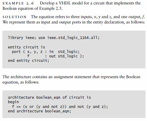
7 Example Bagaimana Design di VHDL?
8 Solution The first of these takes the form of an entity declaration: The circuit is represented in VHDL as an entity, in this case named vat_buzzer. The first line identifies a standard library, ieee, and a package, std_logic_1164, containing definitions that we want to reference in our model
9 The entity has ports, described in the port list of the entity declaration. Each port is given a name and is either an output (out) or an input (in). The port description also specifies the type of each port, that is, the set of values that the port can take on. In this example, each port is of type std_logic, defined by the std_logic_1164 package
10 The std_logic type includes the values '0' and '1', corresponding to the binary values 0 and 1 introduced earlier. The difference is that VHDL requires the quotation marks to distinguish the std_logic values from the numbers 0 and 1.
11 The second part of the VHDL model takes the form of an architecture:
12 Cont The first line of the architecture identifies a design library, dld, and a package, gates, containing definitions of components that we want to include in our model
13 The architecture also references the definitions in the std_logic_1164 package, but since we identified that package and its library in the entity declaration, we don t need to duplicate the library and use clauses in the architecture.
14 The architecture is named struct and is associated with the vat_buzzer entity. Within the architecture, a number of signals are declared for connecting the components together. Each signal is given a name and has a specified type, in this case, std_logic.
15 The architecture is named struct and is associated with the vat_buzzer entity. Within the architecture, a number of signals are declared for connecting the components together. Each signal is given a name and has a specified type, in this case, std_logic.
16 Between the begin and end lines, the architecture contains a number of component instances Each has a label to distinguish it, and specifies which kind of component is instantiated. For example, inv_0 is an instance of the inv component, representing the inverter for vat 0 in the circuit
17 The vat buzzer Circuit, Showing signal names and component label
18 For example, the inverter inv_0 has the input above_25_0 connected to its first port and the signal below_25_0 connected to its second port. We have also included some comments in this architecture to provide documentation.

19 an alternative architecture:
20 Combinational basics Bagaimana dalam VHDL?
21 Solusi
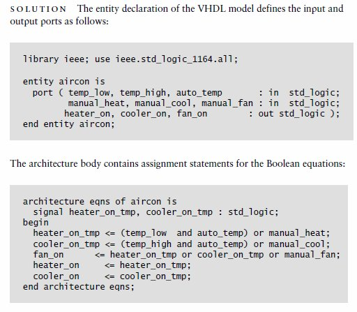
22 Example Develop a VHDL model for a combinational circuit that implements the following three Boolean equations, representing part of the control logic for an air conditioner: Heater_on = temp_low auto_temp + manual_heat cooler_on =temp_high auto_temp + manual_cool fan_on = heater_on + cooler_on + manual_fan
23
24 Circuits corresponding to the assignment statements for the air conditioner control logic.
25 Develop a VHDL model for the 3-bit 2-to-1 multiplexer. Circuit Multiplexer Simbol

26

27 Numeric Basic Develop a VHDL model of a 4-to-1 multiplexer that selects among four unsigned 6-bit integers.

28 The first line identifies the ieee library and the two packages std_logic_1164 and numeric_std that we want to use in our model. The input ports a0 through a3 and the output port z are all 6-bit unsigned vectors, indexed from 5 down to 0. We choose this index range so that the index of each bit in a vector corresponds to the power of its binary weight. The input port sel, used to select among the inputs, is of type std_logic_vector, since we are not interpreting it as representing a number. The corresponding architecture is:
29 Kerjakan di rumah Develop a VHDL behavioral model of an adder/ subtracter for 12-bit unsigned binary numbers. The circuit has data inputs x and y, a data output s, a control input mode that is 0 for addition and 1 for subtraction, and an output ovf_unf that is 1 when an addition overflow or a subtraction underflow occurs.
30 Sequential Basic Develop a VHDL model for a pipelined circuit that computes the average of corresponding values in three streams of input values, a, b and c. The pipeline consists of three stages: the first stage sums values of a and b and saves the value of c; the second stage adds on the saved value of c; and the third stage divides by three. The inputs and output are all signed fixed-point numbers indexed from 5 down to -8.

31 Solution

32 Cont
33 Design a circuit that counts 16 clock cycles and produces a control signal, ctrl, that is 1 during every eighth and twelfth cycle. solution We need a 4-bit counter, since 16=2^4. The counter counts from 0 to 15 and then wraps back to 0. During the eighth cycle, the counter value is 7 (01112), and during the twelfth cycle, the counter value is 11 (10112). We can generate the control signal by decoding the two required counter values and forming the logical OR of the decoded signal
34 The architecture contains a process that represents the counter. It is similar in form to a process for an edge-triggered register. The difference is that the value assigned to the count_value output on a rising clock edge is the incremented count value. The assignment to count_value represents the update of the value stored in the register, and the addition of 1 represents the incrementer. The final assignment statement in the architecture represents the decoder.

35 The entity and architecture are
Digital Design with VHDL
 Digital Design with VHDL CSE 560M Lecture 5 Shakir James Shakir James 1 Plan for Today Announcement Commentary due Wednesday HW1 assigned today. Begin immediately! Questions VHDL help session Assignment
VHDL Test Bench Tutorial
 University of Pennsylvania Department of Electrical and Systems Engineering ESE171 - Digital Design Laboratory VHDL Test Bench Tutorial Purpose The goal of this tutorial is to demonstrate how to automate
ECE 3401 Lecture 7. Concurrent Statements & Sequential Statements (Process)
") ECE 3401 Lecture 7 Concurrent Statements & Sequential Statements (Process) Concurrent Statements VHDL provides four different types of concurrent statements namely: Signal Assignment Statement Simple Assignment
ECE 3401 Lecture 7 Concurrent Statements & Sequential Statements (Process) Concurrent Statements VHDL provides four different types of concurrent statements namely: Signal Assignment Statement Simple Assignment
ASYNCHRONOUS COUNTERS
 LB no.. SYNCHONOUS COUNTES. Introduction Counters are sequential logic circuits that counts the pulses applied at their clock input. They usually have 4 bits, delivering at the outputs the corresponding
Lecture 8: Synchronous Digital Systems
 Lecture 8: Synchronous Digital Systems The distinguishing feature of a synchronous digital system is that the circuit only changes in response to a system clock. For example, consider the edge triggered
LAB #3 VHDL RECOGNITION AND GAL IC PROGRAMMING USING ALL-11 UNIVERSAL PROGRAMMER
 LAB #3 VHDL RECOGNITION AND GAL IC PROGRAMMING USING ALL-11 UNIVERSAL PROGRAMMER OBJECTIVES 1. Learn the basic elements of VHDL that are implemented in Warp. 2. Build a simple application using VHDL and
Chapter 4 Register Transfer and Microoperations. Section 4.1 Register Transfer Language
 Chapter 4 Register Transfer and Microoperations Section 4.1 Register Transfer Language Digital systems are composed of modules that are constructed from digital components, such as registers, decoders,
VHDL GUIDELINES FOR SYNTHESIS
 VHDL GUIDELINES FOR SYNTHESIS Claudio Talarico For internal use only 1/19 BASICS VHDL VHDL (Very high speed integrated circuit Hardware Description Language) is a hardware description language that allows
Experiment # 9. Clock generator circuits & Counters. Eng. Waleed Y. Mousa
 Experiment # 9 Clock generator circuits & Counters Eng. Waleed Y. Mousa 1. Objectives: 1. Understanding the principles and construction of Clock generator. 2. To be familiar with clock pulse generation
Designing Digital Circuits a modern approach. Jonathan Turner
 Designing Digital Circuits a modern approach Jonathan Turner 2 Contents I First Half 5 1 Introduction to Designing Digital Circuits 7 1.1 Getting Started.......................... 7 1.2 Gates and Flip
Systems I: Computer Organization and Architecture
 Systems I: omputer Organization and Architecture Lecture 8: Registers and ounters Registers A register is a group of flip-flops. Each flip-flop stores one bit of data; n flip-flops are required to store
In this example the length of the vector is determined by D length and used for the index variable.
 Loops Loop statements are a catagory of control structures that allow you to specify repeating sequences of behavior in a circuit. There are three primary types of loops in VHDL: for loops, while loops,
Let s put together a Manual Processor
 Lecture 14 Let s put together a Manual Processor Hardware Lecture 14 Slide 1 The processor Inside every computer there is at least one processor which can take an instruction, some operands and produce
Design Example: Counters. Design Example: Counters. 3-Bit Binary Counter. 3-Bit Binary Counter. Other useful counters:
 Design Eample: ers er: a sequential circuit that repeats a specified sequence of output upon clock pulses. A,B,C,, Z. G, O, T, E, R, P, S,!.,,,,,,,7. 7,,,,,,,.,,,,,,,,,,,. Binary counter: follows the binary
Gates, Plexers, Decoders, Registers, Addition and Comparison
 Introduction to Digital Logic Autumn 2008 Gates, Plexers, Decoders, Registers, Addition and Comparison karl.marklund@it.uu.se ...open up a command shell and type logisim and press enter to start Logisim.
Counters and Decoders
 Physics 3330 Experiment #10 Fall 1999 Purpose Counters and Decoders In this experiment, you will design and construct a 4-bit ripple-through decade counter with a decimal read-out display. Such a counter
Digital Logic Design. Basics Combinational Circuits Sequential Circuits. Pu-Jen Cheng
 Digital Logic Design Basics Combinational Circuits Sequential Circuits Pu-Jen Cheng Adapted from the slides prepared by S. Dandamudi for the book, Fundamentals of Computer Organization and Design. Introduction
Step : Create Dependency Graph for Data Path Step b: 8-way Addition? So, the data operations are: 8 multiplications one 8-way addition Balanced binary
 RTL Design RTL Overview Gate-level design is now rare! design automation is necessary to manage the complexity of modern circuits only library designers use gates automated RTL synthesis is now almost
Chapter 7. Registers & Register Transfers. J.J. Shann. J. J. Shann
 Chapter 7 Registers & Register Transfers J. J. Shann J.J. Shann Chapter Overview 7- Registers and Load Enable 7-2 Register Transfers 7-3 Register Transfer Operations 7-4 A Note for VHDL and Verilog Users
Gates, Circuits, and Boolean Algebra
 Gates, Circuits, and Boolean Algebra Computers and Electricity A gate is a device that performs a basic operation on electrical signals Gates are combined into circuits to perform more complicated tasks
earlier in the semester: The Full adder above adds two bits and the output is at the end. So if we do this eight times, we would have an 8-bit adder.
 The circuit created is an 8-bit adder. The 8-bit adder adds two 8-bit binary inputs and the result is produced in the output. In order to create a Full 8-bit adder, I could use eight Full -bit adders and
Memory Elements. Combinational logic cannot remember
 Memory Elements Combinational logic cannot remember Output logic values are function of inputs only Feedback is needed to be able to remember a logic value Memory elements are needed in most digital logic
Binary Adders: Half Adders and Full Adders
 Binary Adders: Half Adders and Full Adders In this set of slides, we present the two basic types of adders: 1. Half adders, and 2. Full adders. Each type of adder functions to add two binary bits. In order
To design digital counter circuits using JK-Flip-Flop. To implement counter using 74LS193 IC.
 8.1 Objectives To design digital counter circuits using JK-Flip-Flop. To implement counter using 74LS193 IC. 8.2 Introduction Circuits for counting events are frequently used in computers and other digital
Design: a mod-8 Counter
 Design: a mod-8 Counter A mod-8 counter stores a integer value, and increments that value (say) on each clock tick, and wraps around to 0 if the previous stored value was 7. So, the stored value follows
Having read this workbook you should be able to: recognise the arrangement of NAND gates used to form an S-R flip-flop.
 Objectives Having read this workbook you should be able to: recognise the arrangement of NAND gates used to form an S-R flip-flop. describe how such a flip-flop can be SET and RESET. describe the disadvantage
Quartus II Introduction for VHDL Users
 Quartus II Introduction for VHDL Users This tutorial presents an introduction to the Quartus II software. It gives a general overview of a typical CAD flow for designing circuits that are implemented by
Chapter 2 Logic Gates and Introduction to Computer Architecture
 Chapter 2 Logic Gates and Introduction to Computer Architecture 2.1 Introduction The basic components of an Integrated Circuit (IC) is logic gates which made of transistors, in digital system there are
Understanding Logic Design
 Understanding Logic Design ppendix of your Textbook does not have the needed background information. This document supplements it. When you write add DD R0, R1, R2, you imagine something like this: R1
ETEC 2301 Programmable Logic Devices. Chapter 10 Counters. Shawnee State University Department of Industrial and Engineering Technologies
 ETEC 2301 Programmable Logic Devices Chapter 10 Counters Shawnee State University Department of Industrial and Engineering Technologies Copyright 2007 by Janna B. Gallaher Asynchronous Counter Operation
SECTION C [short essay] [Not to exceed 120 words, Answer any SIX questions. Each question carries FOUR marks] 6 x 4=24 marks
![SECTION C [short essay] [Not to exceed 120 words, Answer any SIX questions. Each question carries FOUR marks] 6 x 4=24 marks](/thumbs/35/17285180.jpg "SECTION C [short essay] [Not to exceed 120 words, Answer any SIX questions. Each question carries FOUR marks] 6 x 4=24 marks") UNIVERSITY OF KERALA First Degree Programme in Computer Applications Model Question Paper Semester I Course Code- CP 1121 Introduction to Computer Science TIME : 3 hrs Maximum Mark: 80 SECTION A [Very
UNIVERSITY OF KERALA First Degree Programme in Computer Applications Model Question Paper Semester I Course Code- CP 1121 Introduction to Computer Science TIME : 3 hrs Maximum Mark: 80 SECTION A [Very
CHAPTER 3 Boolean Algebra and Digital Logic
 CHAPTER 3 Boolean Algebra and Digital Logic 3.1 Introduction 121 3.2 Boolean Algebra 122 3.2.1 Boolean Expressions 123 3.2.2 Boolean Identities 124 3.2.3 Simplification of Boolean Expressions 126 3.2.4
BINARY CODED DECIMAL: B.C.D.
 BINARY CODED DECIMAL: B.C.D. ANOTHER METHOD TO REPRESENT DECIMAL NUMBERS USEFUL BECAUSE MANY DIGITAL DEVICES PROCESS + DISPLAY NUMBERS IN TENS IN BCD EACH NUMBER IS DEFINED BY A BINARY CODE OF 4 BITS.
INTRODUCTION TO DIGITAL SYSTEMS. IMPLEMENTATION: MODULES (ICs) AND NETWORKS IMPLEMENTATION OF ALGORITHMS IN HARDWARE
 AND NETWORKS IMPLEMENTATION OF ALGORITHMS IN HARDWARE") INTRODUCTION TO DIGITAL SYSTEMS 1 DESCRIPTION AND DESIGN OF DIGITAL SYSTEMS FORMAL BASIS: SWITCHING ALGEBRA IMPLEMENTATION: MODULES (ICs) AND NETWORKS IMPLEMENTATION OF ALGORITHMS IN HARDWARE COURSE EMPHASIS:
INTRODUCTION TO DIGITAL SYSTEMS 1 DESCRIPTION AND DESIGN OF DIGITAL SYSTEMS FORMAL BASIS: SWITCHING ALGEBRA IMPLEMENTATION: MODULES (ICs) AND NETWORKS IMPLEMENTATION OF ALGORITHMS IN HARDWARE COURSE EMPHASIS:
Digital Design with Synthesizable VHDL
 Digital Design with Synthesizable VHDL Prof. Stephen A. Edwards Columbia University Spring 2012 Combinational Logic in a Dataflow Style Hierarchy: Instantiating Components (entities) Combinational Logic
ON SUITABILITY OF FPGA BASED EVOLVABLE HARDWARE SYSTEMS TO INTEGRATE RECONFIGURABLE CIRCUITS WITH HOST PROCESSING UNIT
 216 ON SUITABILITY OF FPGA BASED EVOLVABLE HARDWARE SYSTEMS TO INTEGRATE RECONFIGURABLE CIRCUITS WITH HOST PROCESSING UNIT *P.Nirmalkumar, **J.Raja Paul Perinbam, @S.Ravi and #B.Rajan *Research Scholar,
Life Cycle of a Memory Request. Ring Example: 2 requests for lock 17
 Life Cycle of a Memory Request (1) Use AQR or AQW to place address in AQ (2) If A[31]==0, check for hit in DCache Ring (3) Read Hit: place cache word in RQ; Write Hit: replace cache word with WQ RDDest/RDreturn
Combinational-Circuit Building Blocks
 May 9, 24 :4 vra6857_ch6 Sheet number Page number 35 black chapter 6 Combinational-Circuit Building Blocks Chapter Objectives In this chapter you will learn about: Commonly used combinational subcircuits
12. A B C A B C A B C 1 A B C A B C A B C JK-FF NETr
 2..,.,.. Flip-Flops :, Flip-Flops, Flip Flop. ( MOD)... -8 8, 7 ( ).. n Flip-Flops. n Flip-Flops : 2 n. 2 n, Modulo. (-5) -4 ( -), (-) - ( -).. / A A A 2 3 4 5 MOD-5 6 MOD-6 7 MOD-7 8 9 / A A A 2 3 4 5
Lab 1: Full Adder 0.0
 Lab 1: Full Adder 0.0 Introduction In this lab you will design a simple digital circuit called a full adder. You will then use logic gates to draw a schematic for the circuit. Finally, you will verify
Finite State Machine Design and VHDL Coding Techniques
 Finite State Machine Design and VHDL Coding Techniques Iuliana CHIUCHISAN, Alin Dan POTORAC, Adrian GRAUR "Stefan cel Mare" University of Suceava str.universitatii nr.13, RO-720229 Suceava iulia@eed.usv.ro,
A Verilog HDL Test Bench Primer Application Note
 A Verilog HDL Test Bench Primer Application Note Table of Contents Introduction...1 Overview...1 The Device Under Test (D.U.T.)...1 The Test Bench...1 Instantiations...2 Figure 1- DUT Instantiation...2
Digital Systems. Syllabus 8/18/2010 1
 Digital Systems Syllabus 1 Course Description: This course covers the design and implementation of digital systems. Topics include: combinational and sequential digital circuits, minimization methods,
CHAPTER 11: Flip Flops
 CHAPTER 11: Flip Flops In this chapter, you will be building the part of the circuit that controls the command sequencing. The required circuit must operate the counter and the memory chip. When the teach
DEPARTMENT OF INFORMATION TECHNLOGY
 DRONACHARYA GROUP OF INSTITUTIONS, GREATER NOIDA Affiliated to Mahamaya Technical University, Noida Approved by AICTE DEPARTMENT OF INFORMATION TECHNLOGY Lab Manual for Computer Organization Lab ECS-453
Optimising the resource utilisation in high-speed network intrusion detection systems.
 Optimising the resource utilisation in high-speed network intrusion detection systems. Gerald Tripp www.kent.ac.uk Network intrusion detection Network intrusion detection systems are provided to detect
Faculty of Engineering Student Number:
 Philadelphia University Student Name: Faculty of Engineering Student Number: Dept. of Computer Engineering Final Exam, First Semester: 2012/2013 Course Title: Microprocessors Date: 17/01//2013 Course No:
ECE232: Hardware Organization and Design. Part 3: Verilog Tutorial. http://www.ecs.umass.edu/ece/ece232/ Basic Verilog
 ECE232: Hardware Organization and Design Part 3: Verilog Tutorial http://www.ecs.umass.edu/ece/ece232/ Basic Verilog module ();
Flip-Flops and Sequential Circuit Design. ECE 152A Winter 2012
 Flip-Flops and Sequential Circuit Design ECE 52 Winter 22 Reading ssignment Brown and Vranesic 7 Flip-Flops, Registers, Counters and a Simple Processor 7.5 T Flip-Flop 7.5. Configurable Flip-Flops 7.6
Flip-Flops and Sequential Circuit Design
 Flip-Flops and Sequential Circuit Design ECE 52 Winter 22 Reading ssignment Brown and Vranesic 7 Flip-Flops, Registers, Counters and a Simple Processor 7.5 T Flip-Flop 7.5. Configurable Flip-Flops 7.6
EE360: Digital Design I Course Syllabus
 : Course Syllabus Dr. Mohammad H. Awedh Fall 2008 Course Description This course introduces students to the basic concepts of digital systems, including analysis and design. Both combinational and sequential
Lecture-3 MEMORY: Development of Memory:
 Lecture-3 MEMORY: It is a storage device. It stores program data and the results. There are two kind of memories; semiconductor memories & magnetic memories. Semiconductor memories are faster, smaller,
1. True or False? A voltage level in the range 0 to 2 volts is interpreted as a binary 1.
 File: chap04, Chapter 04 1. True or False? A voltage level in the range 0 to 2 volts is interpreted as a binary 1. 2. True or False? A gate is a device that accepts a single input signal and produces one
Digital Logic Design Sequential circuits
 Digital Logic Design Sequential circuits Dr. Eng. Ahmed H. Madian E-mail: ahmed.madian@guc.edu.eg Dr. Eng. Rania.Swief E-mail: rania.swief@guc.edu.eg Dr. Eng. Ahmed H. Madian Registers An n-bit register
(Refer Slide Time: 00:01:16 min)
") Digital Computer Organization Prof. P. K. Biswas Department of Electronic & Electrical Communication Engineering Indian Institute of Technology, Kharagpur Lecture No. # 04 CPU Design: Tirning & Control
Digital Computer Organization Prof. P. K. Biswas Department of Electronic & Electrical Communication Engineering Indian Institute of Technology, Kharagpur Lecture No. # 04 CPU Design: Tirning & Control
CSE140 Homework #7 - Solution
 CSE140 Spring2013 CSE140 Homework #7 - Solution You must SHOW ALL STEPS for obtaining the solution. Reporting the correct answer, without showing the work performed at each step will result in getting
Systems I: Computer Organization and Architecture
 Systems I: Computer Organization and Architecture Lecture 9 - Register Transfer and Microoperations Microoperations Digital systems are modular in nature, with modules containing registers, decoders, arithmetic
COMBINATIONAL CIRCUITS
 COMBINATIONAL CIRCUITS http://www.tutorialspoint.com/computer_logical_organization/combinational_circuits.htm Copyright tutorialspoint.com Combinational circuit is a circuit in which we combine the different
A New Paradigm for Synchronous State Machine Design in Verilog
 A New Paradigm for Synchronous State Machine Design in Verilog Randy Nuss Copyright 1999 Idea Consulting Introduction Synchronous State Machines are one of the most common building blocks in modern digital
EE361: Digital Computer Organization Course Syllabus
 EE361: Digital Computer Organization Course Syllabus Dr. Mohammad H. Awedh Spring 2014 Course Objectives Simply, a computer is a set of components (Processor, Memory and Storage, Input/Output Devices)
Testing & Verification of Digital Circuits ECE/CS 5745/6745. Hardware Verification using Symbolic Computation
 Testing & Verification of Digital Circuits ECE/CS 5745/6745 Hardware Verification using Symbolic Computation Instructor: Priyank Kalla (kalla@ece.utah.edu) 3 Credits Mon, Wed, 1:25-2:45pm, WEB L105 Office
Discrete event modeling: VHDL
 12 Discrete event modeling: VHDL Peter Marwedel Informatik 12 Univ. Dortmund Germany Models of computation VHDL as a prominent example of discrete event modeling: Communication/ Computation FSM Data flow
Using Xilinx ISE for VHDL Based Design
 ECE 561 Project 4-1 - Using Xilinx ISE for VHDL Based Design In this project you will learn to create a design module from VHDL code. With Xilinx ISE, you can easily create modules from VHDL code using
State Machines in VHDL
 State Machines in VHDL Implementing state machines in VHDL is fun and easy provided you stick to some fairly well established forms. These styles for state machine coding given here is not intended to
Digital Fundamentals. Lab 8 Asynchronous Counter Applications
 Richland College Engineering Technology Rev. 0 B. Donham Rev. 1 (7/2003). Horne Rev. 2 (1/2008). Bradbury Digital Fundamentals CETT 1425 Lab 8 Asynchronous Counter Applications Name: Date: Objectives:
Sistemas Digitais I LESI - 2º ano
 Sistemas Digitais I LESI - 2º ano Lesson 6 - Combinational Design Practices Prof. João Miguel Fernandes (miguel@di.uminho.pt) Dept. Informática UNIVERSIDADE DO MINHO ESCOLA DE ENGENHARIA - PLDs (1) - The
Sequential Logic. (Materials taken from: Principles of Computer Hardware by Alan Clements )
") Sequential Logic (Materials taken from: Principles of Computer Hardware by Alan Clements ) Sequential vs. Combinational Circuits Combinatorial circuits: their outputs are computed entirely from their present
Sequential Logic (Materials taken from: Principles of Computer Hardware by Alan Clements ) Sequential vs. Combinational Circuits Combinatorial circuits: their outputs are computed entirely from their present
GETTING STARTED WITH PROGRAMMABLE LOGIC DEVICES, THE 16V8 AND 20V8
 GETTING STARTED WITH PROGRAMMABLE LOGIC DEVICES, THE 16V8 AND 20V8 Robert G. Brown All Rights Reserved August 25, 2000 Alta Engineering 58 Cedar Lane New Hartford, CT 06057-2905 (860) 489-8003 www.alta-engineering.com
Cascaded Counters. Page 1 BYU
 Cascaded Counters Page 1 Mod-N Counters Generally we are interested in counters that count up to specific count values Not just powers of 2 A mod-n counter has N states Counts from 0 to N-1 then rolls
LAB #4 Sequential Logic, Latches, Flip-Flops, Shift Registers, and Counters
 LAB #4 Sequential Logic, Latches, Flip-Flops, Shift Registers, and Counters LAB OBJECTIVES 1. Introduction to latches and the D type flip-flop 2. Use of actual flip-flops to help you understand sequential
University of St. Thomas ENGR 230 ---- Digital Design 4 Credit Course Monday, Wednesday, Friday from 1:35 p.m. to 2:40 p.m. Lecture: Room OWS LL54
 Fall 2005 Instructor Texts University of St. Thomas ENGR 230 ---- Digital Design 4 Credit Course Monday, Wednesday, Friday from 1:35 p.m. to 2:40 p.m. Lecture: Room OWS LL54 Lab: Section 1: OSS LL14 Tuesday
E158 Intro to CMOS VLSI Design. Alarm Clock
 E158 Intro to CMOS VLSI Design Alarm Clock Sarah Yi & Samuel (Tae) Lee 4/19/2010 Introduction The Alarm Clock chip includes the basic functions of an alarm clock such as a running clock time and alarm
The components. E3: Digital electronics. Goals:
 E3: Digital electronics Goals: Basic understanding of logic circuits. Become familiar with the most common digital components and their use. Equipment: 1 st. LED bridge 1 st. 7-segment display. 2 st. IC
Floating Point Fused Add-Subtract and Fused Dot-Product Units
 Floating Point Fused Add-Subtract and Fused Dot-Product Units S. Kishor [1], S. P. Prakash [2] PG Scholar (VLSI DESIGN), Department of ECE Bannari Amman Institute of Technology, Sathyamangalam, Tamil Nadu,
Printed Circuit Board Design with HDL Designer
 Printed Circuit Board Design with HDL Designer Tom Winkert Teresa LaFourcade NASNGoddard Space Flight Center 301-286-291 7 NASNGoddard Space Flight Center 301-286-0019 tom.winkert8 nasa.gov teresa. 1.
if-then else : 2-1 mux mux: process (A, B, Select) begin if (select= 1 ) then Z <= A; else Z <= B; end if; end process;
 begin if (select= 1 ) then Z <= A; else Z <= B; end if; end process;") if-then else : 2-1 mux mux: process (A, B, Select) begin if (select= 1 ) then Z
if-then else : 2-1 mux mux: process (A, B, Select) begin if (select= 1 ) then Z
Counters. Present State Next State A B A B 0 0 0 1 0 1 1 0 1 0 1 1 1 1 0 0
 ounter ounters ounters are a specific type of sequential circuit. Like registers, the state, or the flip-flop values themselves, serves as the output. The output value increases by one on each clock cycle.
Digital Electronics Detailed Outline
 Digital Electronics Detailed Outline Unit 1: Fundamentals of Analog and Digital Electronics (32 Total Days) Lesson 1.1: Foundations and the Board Game Counter (9 days) 1. Safety is an important concept
Digital Systems Design. VGA Video Display Generation
 Digital Systems Design Video Signal Generation for the Altera DE Board Dr. D. J. Jackson Lecture 12-1 VGA Video Display Generation A VGA signal contains 5 active signals Two TTL compatible signals for
The Designer's Guide to VHDL
 The Designer's Guide to VHDL Third Edition Peter J. Ashenden EDA CONSULTANT, ASHENDEN DESIGNS PTY. LTD. ADJUNCT ASSOCIATE PROFESSOR, ADELAIDE UNIVERSITY AMSTERDAM BOSTON HEIDELBERG LONDON m^^ yj 1 ' NEW
Today. Binary addition Representing negative numbers. Andrew H. Fagg: Embedded Real- Time Systems: Binary Arithmetic
 Today Binary addition Representing negative numbers 2 Binary Addition Consider the following binary numbers: 0 0 1 0 0 1 1 0 0 0 1 0 1 0 1 1 How do we add these numbers? 3 Binary Addition 0 0 1 0 0 1 1
DDS. 16-bit Direct Digital Synthesizer / Periodic waveform generator Rev. 1.4. Key Design Features. Block Diagram. Generic Parameters.
 Key Design Features Block Diagram Synthesizable, technology independent VHDL IP Core 16-bit signed output samples 32-bit phase accumulator (tuning word) 32-bit phase shift feature Phase resolution of 2π/2
CNC FOR EDM MACHINE TOOL HARDWARE STRUCTURE. Ioan Lemeni
 CNC FOR EDM MACHINE TOOL HARDWARE STRUCTURE Ioan Lemeni Computer and Communication Engineering Department Faculty of Automation, Computers and Electronics University of Craiova 13, A.I. Cuza, Craiova,
Take-Home Exercise. z y x. Erik Jonsson School of Engineering and Computer Science. The University of Texas at Dallas
 Take-Home Exercise Assume you want the counter below to count mod-6 backward. That is, it would count 0-5-4-3-2-1-0, etc. Assume it is reset on startup, and design the wiring to make the counter count
A Platform for Visualizing Digital Circuit Synthesis with VHDL
 A Platform for Visualizing Digital Circuit Synthesis with VHDL Abdulhadi Shoufan shoufan@iss.tudarmstadt.de Zheng Lu zheng@iss.tudarmstadt.de Technische Universität Darmstadt Dept. of Computer Science
DIGITAL COUNTERS. Q B Q A = 00 initially. Q B Q A = 01 after the first clock pulse.
 DIGITAL COUNTERS http://www.tutorialspoint.com/computer_logical_organization/digital_counters.htm Copyright tutorialspoint.com Counter is a sequential circuit. A digital circuit which is used for a counting
Efficient Teaching of Digital Design with Automated Assessment and Feedback
 Efficient Teaching of Digital Design with Automated Assessment and Feedback 1 Paul W. Nutter, Member, IEEE, 2 Vasilis F. Pavlidis, Member, IEEE, and 2 Jeffrey Pepper 1 Nano Engineering and Storage Technology
Introduction to Programmable Logic Devices. John Coughlan RAL Technology Department Detector & Electronics Division
 Introduction to Programmable Logic Devices John Coughlan RAL Technology Department Detector & Electronics Division PPD Lectures Programmable Logic is Key Underlying Technology. First-Level and High-Level
ModelSim-Altera Software Simulation User Guide
 ModelSim-Altera Software Simulation User Guide ModelSim-Altera Software Simulation User Guide 101 Innovation Drive San Jose, CA 95134 www.altera.com UG-01102-2.0 Document last updated for Altera Complete
Admin. ECE 550: Fundamentals of Computer Systems and Engineering. Last time. VHDL: Behavioral vs Structural. Memory Elements
 Admin C 55: Fundamentals of Computer ystems and ngineering torage and Clocking eading Finish up Chapter ecitation How is it going? VHL questions/issues? Homework Homework ubmissions vis akai C 55 (Hilton):
CS101 Lecture 26: Low Level Programming. John Magee 30 July 2013 Some material copyright Jones and Bartlett. Overview/Questions
 CS101 Lecture 26: Low Level Programming John Magee 30 July 2013 Some material copyright Jones and Bartlett 1 Overview/Questions What did we do last time? How can we control the computer s circuits? How
2 n. (finite state machines).
.") . - S,, T FI-FO. ;. 2. ;,,.,, (sequential).. ( )... 3. ; (state) (state variables),.,, (state)..,,..,,. 4. ;. n 2 n., 2 n,, (finite state machines). 5. (feedback).,..,.,,. 6.,,., ( ).. ,.,. 7., ( ).,..,
. - S,, T FI-FO. ;. 2. ;,,.,, (sequential).. ( )... 3. ; (state) (state variables),.,, (state)..,,..,,. 4. ;. n 2 n., 2 n,, (finite state machines). 5. (feedback).,..,.,,. 6.,,., ( ).. ,.,. 7., ( ).,..,
Hardware Implementation of the Stone Metamorphic Cipher
 International Journal of Computer Science & Network Security VOL.10 No.8, 2010 Hardware Implementation of the Stone Metamorphic Cipher Rabie A. Mahmoud 1, Magdy Saeb 2 1. Department of Mathematics, Faculty
Combinational Logic Design Process
 Combinational Logic Design Process Create truth table from specification Generate K-maps & obtain logic equations Draw logic diagram (sharing common gates) Simulate circuit for design verification Debug
EE 261 Introduction to Logic Circuits. Module #2 Number Systems
 EE 261 Introduction to Logic Circuits Module #2 Number Systems Topics A. Number System Formation B. Base Conversions C. Binary Arithmetic D. Signed Numbers E. Signed Arithmetic F. Binary Codes Textbook
Computer Architecture TDTS10
 why parallelism? Performance gain from increasing clock frequency is no longer an option. Outline Computer Architecture TDTS10 Superscalar Processors Very Long Instruction Word Processors Parallel computers
SEQUENTIAL CIRCUITS. Block diagram. Flip Flop. S-R Flip Flop. Block Diagram. Circuit Diagram
 SEQUENTIAL CIRCUITS http://www.tutorialspoint.com/computer_logical_organization/sequential_circuits.htm Copyright tutorialspoint.com The combinational circuit does not use any memory. Hence the previous
Lesson 12 Sequential Circuits: Flip-Flops
 Lesson 12 Sequential Circuits: Flip-Flops 1. Overview of a Synchronous Sequential Circuit We saw from last lesson that the level sensitive latches could cause instability in a sequential system. This instability
Digital Design and Synthesis INTRODUCTION
 Digital Design and Synthesis INTRODUCTION The advances in digital design owe its progress to 3 factors. First the acceleration at which the CMOS technology has advanced in last few decades and the way
Chapter 7 Memory and Programmable Logic
 NCNU_2013_DD_7_1 Chapter 7 Memory and Programmable Logic 71I 7.1 Introduction ti 7.2 Random Access Memory 7.3 Memory Decoding 7.5 Read Only Memory 7.6 Programmable Logic Array 77P 7.7 Programmable Array