MODEL PCT-A CROSS SECTION
|
|
|
- Conrad Rodgers
- 7 years ago
- Views:
Transcription

1
2
3
4
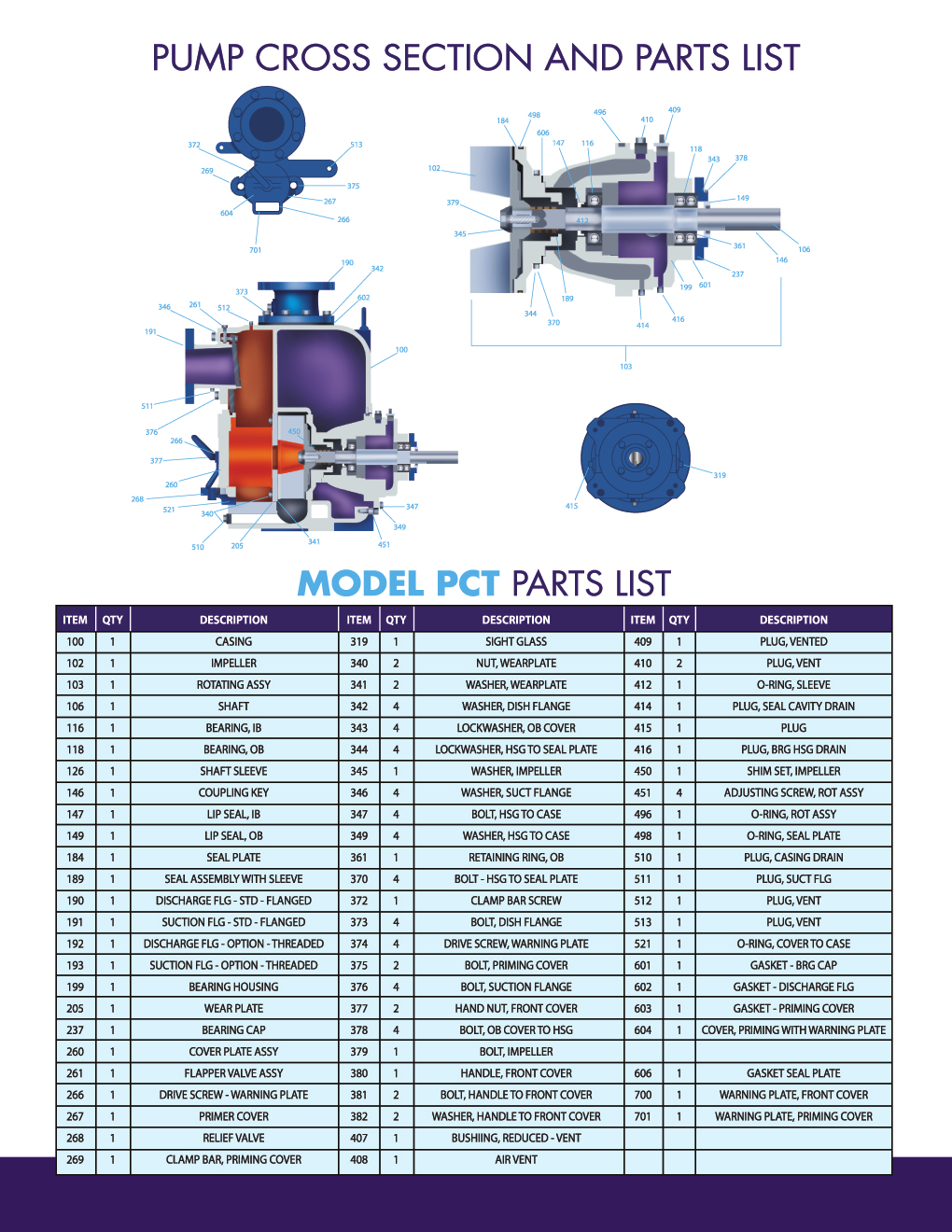
5 MODEL PCT-A CROSS SECTION

6 PUMP MODEL PCT-A PARTS LIST

7 INSTALLATION, OPERATION, AND MAINTENANCE MANUAL MODEL PCT-A SELF PRIMING TRASH HANDLING PUMP Pump Components, LLC 4526 Ogeechee Rd. Savannah, GA P (912) F (912) PCT-A NONCLOG Page 1
8 TABLE OF CONTENTS 1. INTRODUCTION 3 LIABILITY 3 2. RECEIPT and STORAGE 3 RECEIVING THE PUMP 3 STORING THE PUMP 3 HANDLING 4 3. INSTALLATION 4 LOCATION 4 FOUNDATION 4 PIPING CONNECTION 5 ALIGNMENT 6 BYPASS LINES 6 AUTOMATIC AIR RELEASE 7 4. OPERATION 7 LUBRICATION 8 IMPELLER CLEARANCE 8 PRIMING 9 START UP 9 SHUT DOWN DISASSEMBLY PROCEDURES ASSEMBLY PROCEDURES 12 ROTATING ASSEMBLY 12 BACK PLATE COVER ASSEMBLY 13 SUCTION HEAD ASSEMBLY APPENDIX 14 PUMP CROSS SECTION & PARTS LIST WARRANTY 15 PCT-A NONCLOG Page 2

9 INSTALLATION, OPERATION, AND MAINTENANCE MANUAL 1. INTRODUCTION This manual is intended to assist those responsible for the installation, operation and maintenance of the Pump Components model PCT-A Self Priming Nonclog Process pump. It is recommended that this entire book be read before attempting to install, operate or repair this pump. Properly installed, your pump will give you satisfactory, dependable service. We urge that you carefully read these step by-step instructions, to eliminate any problems of installation, operation or repair. Failure to read and comply with installation and operating instructions will void the responsibility of the manufacturer and may also result in bodily injury as well as property damage. LIABILITY Pump Components shall not be liable for physical injury, damage, or delays caused by failure to observe the instructions for installation, operation and maintenance contained in this manual. 2. RECEIPT AND STORAGE RECEIVING THE PUMP Failure to properly lift and move pump could result in serious personal injury. Immediately upon arrival, carefully inspect the pump for evidence of damage during transit. Immediately report any damage to your Pump Components Distributor. STORING THE PUMP Store the pump in a clean dry place. Do not remove piping connection covers. Rotate the pump shaft by hand at least once per week to maintain a protective film of oil or grease on the bearings. Gaskets can dry out and become brittle over time. Check all gasketed joints before putting pump in service. PCT-A NONCLOG Page 3
10 HANDLING Use care when lifting pumps. Lifting equipment must be able to adequately support the entire assembly. Hoist bare pump using a suitable sling, under the suction flange and motor. Base plate mounted units can also be moved with slings under the pump casing and driver. Refer to picture below for examples of proper lifting techniques. Inspect all lifting equipment and rigging before lifting pump. Rig pump securely allowing for a proper safety factor. Refer to Table 1 for pump weights. Table 1 Pump Size Weight in Lbs 2" 292 3" 432 4" 664 6" 394 8" " 1750 Figure 1: Proper pump lifting technique. 3. INSTALLATION Operation of this pump without guards and other safety devices in place could result in severe personal injury. LOCATION Locate the pump as close to the liquid supply as practical and select an area that provides easy access for inspection and maintenance. The pump requires clearance in the front of the back cover to permit removal of the cover and easy access to the pump for cleaning and service. The pump is designed to operate with a negative suction supply. Although, it can operate with a positive suction supply. The suction pressure must never exceed 50% of the maximum pressure published on the pump curve. FOUNDATION Use a foundation that is sufficient enough to support pump and driver. It is recommended that the foundation mass be five times the equipment mass. PCT-A NONCLOG Page 4
11 PIPING CONNECTION Pipe or hose can be utilized for suction a discharge lines. Line material must be compatible with the liquid being pumped and able to withstand the maximum pressure in the system plus a conservative safety factor. If hose is used on the suction side it must be rigid wall, reinforced type to prevent collapse when pump is operating. All piping must be independently supported and accurately aligned to the pump flanges. Never use force to align piping to the pump flanges. Whenever practical, run the system piping from the pump. Piping should be as short and straight as possible, when minimizing fittings which increase friction losses. Suction line size must be the same size of the pump suction flange. If a reducer is used, it should be the eccentric type, and installed with the flat portion on top. The suction line should slope up to the suction flange to help reduce air pockets. Piping placed in a sump should be positioned away from any wall by a distance of at least 1.5 times the diameter of the suction line. The submergence of the end of the suction line is vital to efficient pump operation. Recommended submergence is shown in Figure 1. Velocity in feet per second = G.P.M. X 321 / Pipe Area A valve should never be used to throttle the suction line. The discharge line should include a valve that can be used to throttle flow and shutoff. The size of this valve should be equal to the size of the largest discharge line. A check calve in the system should be installed to prevent excessive shock pressure and reverse rotation flow which could cause pump damage. PCT-A NONCLOG Page 5
12 ALIGNMENT Alignment of the driver to the pump is imperative to the operating life of the equipment. Misalignment can lead to bearing failures, coupling wear, and shortened V-belt. Shipping and handling may cause misalignment. Units must be checked before operation. DIRECT COUPLED PUMP a) Use flexible spacer couplings to achieve proper alignment. b) Check and adjust the parallel and angular alignment to within.005 inches prior to connecting the coupling halves. c) Check that driver rotation agrees with pump rotation. d) Install a coupling guard when the pump is aligned. Note: Pumps in hot service will need an alignment check at operating temperatures. BELT DRIVEN PUMP Locate driver shaft parallel to pump shaft. Use a straight edge and belt tensioner to properly set up V-belts. BYPASS LINES Do not operate pump with a closed manual shut off valve in bypass line. This may cause the unprimed pump to circulate while not regaining its prime. This will create overheating and possible explosion. A bypass line is needed when a check valve is in the discharge line. During the priming cycle, air in the suction piping side must be vented to the atmosphere. If a check valve is installed in the discharge line, the discharge side of the pump must be opened to vent the air in the system. The pump will not prime if there is sufficient static head to keep the discharge check valve closed. The bypass line should be at least 1 inch diameter to minimize plugging yet small enough to prevent significantly impacting pump performance. The bypass line must discharge into the sump of an appropriate vessel to prevent a hazardous spill. A bypass liner that returns to the sump must be secured to prevent being drawn into the suction. In applications with less than 30 feet of discharge head, the bypass line should run back to the wet well. Locate the discharge end 6 to 8 inches below the minimum liquid level of the sump. In applications with more than 30 feet of discharge head a significant amount of liquid could be bypassed. This will negatively impact pump efficiency. To improve this condition an automatic PCT-A NONCLOG Page 6
13 air release valve should be installed in the bypass line. See the section Automatic Release Valve. AUTOMATIC AIR RELEASE VALVE (AARV) The AARV is designed to allow ventilation of air during the priming cycle. Once the pump is primed, the AARV will close due to the discharge pressure generated by the pump. A small amount of liquid (1 to 5 gallons per minute) will still bypass when the valve is in the closed position. Each AARV must be sized and adjusted for its specific application. The AARV is installed in the discharge line between the discharge flange and inlet side of the check valve as shown in Figure 2. The inlet must be installed below the center line of the AARV. The discharge of the valve must be safely directed back to the sump appropriate vessel through a bleed line. The bleed line must slope towards the sump or vessel and be one inch or larger in size. 4. OPERATION Do not pump volatile, highly corrosive or flammable liquids with this pump. Death or severe injury could occur. Do not operate pump outside its design envelope. Death or severe injury could occur. PCT-A NONCLOG Page 7
14 LUBRICATION SEAL ASSEMBLY Prior to starting the pump, remove the vented plug and fill with approximately 20 ounces of SAE No. 30 non-detergent oil. The oil level should be just below the plug s tapped hole. BEARINGS SAE No. 30, non-detergent oil is the recommended lubricant. Check the lubricant level regularly in the sight glass (319); maintain level exactly at center of glass. Fill in need through vented plug. IMPELLER CLEARANCE Impeller clearance is the measurement between the impeller (102) and the wear plate (205). This clearance is set at.013 inches during assembly, but may need to be adjusted before initial startup. Electricity can cause electric shock. Lockout power prior to working on pump. Running pumps can create heat and cause hot gasses to form that if not properly releases can cause serious burns. Allow pump to cool completely before servicing. Do not remove any cover plates, fittings or gauges from a heated pump. Check impeller clearance prior to starting the pump. Settings may have changed during transport. SETTING THE IMPELLER CLEARANCE: A change in pump performance may be noted over time by a drop in head or flow or an increase in power required. Performance can usually be renewed by adjusting the impeller clearance. (See Appendix A for a cross section of corresponding model) To set the impeller clearances use the following procedures: PCT-A NONCLOG Page 8
15 PRIMING 1. Lockout power to the pump motor 2. Allow pump to cool if it has been operating 3. Close the suction and discharge valves 4. Remove the casing drain plug (510) 5. Loosen flap valve pin (372) and remove priming cover clamp bar (269) 6. Loosen priming cover (604) 7. Allow pump to drain if it has been operating 8. Remove 4 hex head bolts (370) and then remove the lock washers (343). Reinsert the hex head bolts (370) into there holes. 9. Slowly turn the 4 adjusting screws (451) into the casing in a cris cross pattern 10. Use the hex head bolts (370) minus the lock washers (343) to move the rotating element until the impeller comes in contact with the wear plate (205) 11. Loosen the 4 hex head bolts (370) until a feeler gauge can be inserted against the bearing housing (199) hex head bolts (370) 12. Turn the 4 adjusting screws (451) out of the casing until they are tight against the bearing housing (199) 13. Remove the 4 hex head bolts (370) and add the lock washers (343) 14. Reinstall the 4 hex head bolts (370) and tighten in a cris cross pattern to 60 ft lbs (lubed) of 88 ft lbs (dry) 15. Turn the pump shaft 360 degrees to check for rubbing/ binding. If there is binding, repeat steps 8 thru 15. If there is no rubbing/ binding the impeller clearance is correct 16. Reinstall the casing drain plug (510). Reinstall the priming cover (604) then insert the clamp bar (269) and tighten the flap valve pin (372) Make sure the pump and piping are installed as detailed in this manual. Check all piping joints for tightness and that the pump and driver are secured. Do not operate pump without casing being filled. The pump casing is filled by removing the fill cover (604), loosening the hand screw (267), swing the clamp bar (269) away, removing the cover plate, and filling the casing with pumpage or compatible liquid. Replace the cover, swing the clamp bar into the closed position, and tighten the clamp screw. The liquid level in the casing should be checked when: 1. The pump is first put into service 2. The pump has not been in service for an extended period of time 3. the liquid has had a chance to evaporate The pump will prime and re-prime as necessary only if the casing remains full. START UP Read and understand the operation manual supplied with the driver. Do not operate without guards which comply with ASME B15.1. Driver rotation must agree with pump rotation. PCT-A NONCLOG Page 9
16 LINES WITH A BYPASS If an automatic air release valve (AARV) has been installed it will automatically open allowing air to be evacuated out of the suction line and the pump to prime. It will automatically close after prime is complete. A small amount of liquid (1 to 5 gallons per minute) will continue to be bypassed during regular operation. If an AARV has not been installed, air from the suction line will be discharged through the bypass line. Liquid will continue to circulate thorough the bypass line during regular operation. Do not attempt to prime pump without properly ventilating the discharge line. Pressure head against a check valve can prevent ventilation and cause an explosion. See the section BYPASS LINE for complete instructions. LINES WITHOUT A BYPASS Do not attempt to prime pump without properly ventilating the discharge line. Pressure head against a check valve can prevent ventilation and cause explosion. Open all valves in the discharge line and start the driver. Priming will be indicated by a positive pressure reading on the discharge gauge. The pump will not prime until the air has been evacuated and the suction line is filled with liquid. Shut down the driver if the pump fails to prime within five minutes. Check for clogs and leaks in the suction line. When pump has primed, partially close the discharge throttling valve. This step will fill the line slowly guarding against excess shock pressure. When line is full, adjust valve to required flow. Do not operate pump against a closed discharge valve for extended periods. Operation could cause liquid to boil, building pressures that will damage pump casing, causing rupture or explosion which could cause personal injury or death. LIQUID TEMPERATURE The maximum liquid temperature for this pump is 160 F. The temperature of a liquid can increase due to pumping action. The liquid temperature must be monitored to insure it remains below 160 F at the discharge of the pump. This is particularly true when pumping against a closed or restricted discharge or suction valve as in the case of operating on the left side of the performance curve. Also be aware of changes in the ambient temperature of the liquid e.g. seasonal changes. An overheated pump must be allowed to cool prior to servicing. Do not remove any cover plates, fittings or gauges form an over-heated pump. Allow the pump to cool completely. When cooling is complete, drain the casing by removing the casing drain plug (510). Use extreme care when removing the plug to prevent serious burns. PCT-A NONCLOG Page 10
17 BACK FLUSHING Never back flush the pump with high pressure air or steam. The high pressure could damage the pump and result in personal injury. Never use more than 50% of the maximum operating pressure indicated on the pump curve during back flushing. BEARING TEMPERATURE Do not check bearing temperature by using your hand it is unsafe and inaccurate. Burns can result. Check the temperature with a contact or inferred gun type instrument, 180 F is the maximum temperature for operation. Higher temperatures may be the result of conditions that require attention, such as damaged bearing, low lubricant level, wrong lubricant, misalignment between pump to driver. SHUT DOWN Do not stop the pump suddenly. The resulting hammer or shock wave is transmitted across the entire system including the pump. Damage to the system and/or the pump may result. Gradually close the discharge valve before shutting down the driver. Do not operate pump against a closed discharge valve for extended periods. Operation could cause liquid to boil, building pressures that will damage pump casing, causing rupture or explosion which could cause personal injury or death. If the pump is engine drive, throttle it slowly and allow it to briefly idle before shutting it down. Lockout or disable the driver from being operated. 5. DISASSEMBLY PROCEDURES (SEE APPENDIX A FOR CROSS-SECTION OF PUMP) Back cover and wear plate. 1. Lock out power supply at motor starter 2. Close off discharge suction valves 3. If pumping hot liquid, allow pump to cool 4. Drain casing and flush as needed (510) 5. Loosen two hand nuts (377) and remove. Pull front cover assembly plate (206) from casing 6. Loosen wear plate nut (340) and remove wear plate (205). Inspect for wear and replace if necessary 7. If directly driven, remove coupling and motor. If belt driven, remove belts and sheaves 8. Drain seal cavity lubricant, remove drain plug (414) 9. Wedge a wooden block between impeller (102) vanes and casing (100) Using a strap wrench turn the pump shaft (106) counter clockwise when facing the drive 10. Remove vent plug (410) PCT-A NONCLOG Page 11
18 11. Remove the four housing to case bolts (347). Because the rotating assembly (103) is heavy and not well counter balanced, the lifting tool shown is helpful 12. Remove seal plate gasket (606) and bearing housing o-ring (496) 13. Remove impeller from assembly, loosen and remove impeller socket head screw (379) and washer (345) 14. Remove impeller adjusting shims (450) and record thickness this will aid in reassembly 15. Pull the seal assembly off the shaft, use two stiff wires to pull the stationary element and seat 16. Remove bearing housing drain plug (416), drain oil 17. Remove bearing cap (237) and oil seal (149) 18. Slide shaft (260) out of bearing housing (199) 19. Remove radial oil seal (147) 20. press radial bearing (116) and thrust bearing (180) off from the shaft 21. Clean bearing housing (199) and bearing cup (237) 22. Inspect all parts removed, replace as required The rotating assembly is heavy and not well counter balanced. Use two people for removal to avoid personal injury from lifting the assembly. 6. ASSEMBLY PROCEDURES ROTATING ASSEMBLY (SEE APPENDIX A FOR CROSS-SECTION OF PUMP) To assemble rotating assembly: 1. Clean the disassembled bearing housing (199) 2. Secure the bearing frame to bench or holding stand 3. Install vent, oil and cavity plugs (409,410,414,415,416) 4. Install sight glass (319) 5. Install outboard bearing (118) on shaft (106) retaining ring towards end of shaft 6. Install inboard bearing (116) on shaft (106) 7. Install outboard lip seal (149) in bearing cap (237) 8. Install inboard lip seal (147) in bearing housing (199) 9. Slide shaft bearing assembly into bearing housing (199) from drive end of frame until outboard bearing retaining ring is in its groove in frame 10. Slide bearing cap (237) and gasket (601) over shaft (106) 11. Insert bearing cap bolts through cap (237) and gasket (601) 12. Slide back seal plate (184) and gasket (606) over impeller end of shaft PCT-A NONCLOG Page 12
19 13. Install bolt (377) and lock washer (344) into bearing frame (199) and back seal plate (184) and tighten 14. Slide mechanical seal assembly 9189) over end shaft (106) 15. Install impeller shims (450) over shaft (106) between impeller (102) and mechanical seal assembly (189) 16. Install impeller bolt (379) and impeller washer (345) on to shaft (106) 17. Measure space between impeller (102) and back plate (184). Correct clearance is.026-inches. If not, remove impeller (102) and add of subtract from shim stack (450). Repeat step 16 and When impeller (102) to back seal plate (184) clearance is correct, install impeller bolt (379) and tighten. Rotating assembly is now complete and ready for installing in pump or storing as spare INSTALL ROTATING ASSEMBLY When installing rotating assembly, be sure it has been filled with proper oil SAE 30 (non detergent). Use suitable hoist and rigging to lift assembly. 1. Screw adjusting screws (451) into casing 2. Install new O rings (496) (498) on assembly (103) 3. Slide rotating assembly (103) into the casing (100) 4. Insert the bearing housing to casing bolts (370) into the bearing housing (199), tighten until impeller (102) rubs on front wear plate (205) 5. Refer to the impeller clearance section; follow steps 8 through 15 to adjust impeller (102) clearance BACK COVER ASSEMBLY PCT3A, PCT4A, PCT6A, PCT8A 1. Cover plate assembly (260) wear plate (205) is cleaned inspected 2. If wear plate (205) is worn, replace. Remove to bolts (340) PCT3A, PCT4A, 4 bolts (340) PCT6A, PCT8A 3. Install new wear plate (205) using bolts detailed in step 2; replace cover o-ring (521) 4. Install cover plate assembly (260) into casing (100) and tighten hand nut (377) 5. The pump is now ready to accept the rotating assembly PCT10A SUCTION HEAD ASSEMBLY 2. Install the suction head gasket (square suction ring). Use silicon grease to aid holding gasket in place 3. Use a lifting device and sling to hold suction casing in place 4. Insert the two large suction to casing bolts in the twelve and six-o-clock positions. Tighten the bolts, being careful that the gasket stays in place. Insert the four smaller suction to casing bolts and tighten 5. The pump is now ready to accept the rotating assembly PCT-A NONCLOG Page 13
20 APPENDIX PCT-A NONCLOG Page 14

21 Pump Components, Inc Ogeechee Road, P.O. Box 7551, Savannah, Georgia Tele: (912) Fax: (912) Pump Components, Inc. is pleased to offer our standard THREE YEAR PARTS WARRANTY Pump Components, Inc has been manufacturing replacement parts for industrial centrifugal pumps since Our success has been our ability to reproduce parts that match or exceed the OEM with regard to fit, finish, and materials of construction. We guarantee that our parts will fit the pumps that we reference. As a manufacturer of high quality centrifugal pump parts, Pump Components Inc. warrants the equipment (and component parts) of its own manufacture against faulty workmanship, defects in construction and material faults for 3 (three) full years from the date of shipment. This does not cover normal wear and tear, or mishandling during storage, transport, handling or operation. All O.E.M. names, part numbers, symbols, and descriptions are used for reference only. It is not implied that any pump or part sold by Pump Components, Inc is the product of any other manufacturer other than Pump Components, Inc. PCT-A NONCLOG Page 15
22 Pump Components ~ Since Ogeechee Road, Savannah, Georgia, mikea@pumpcomponents.com Fax: (912) Phone: (912) 233-PUMP or (912) [PC196]
23

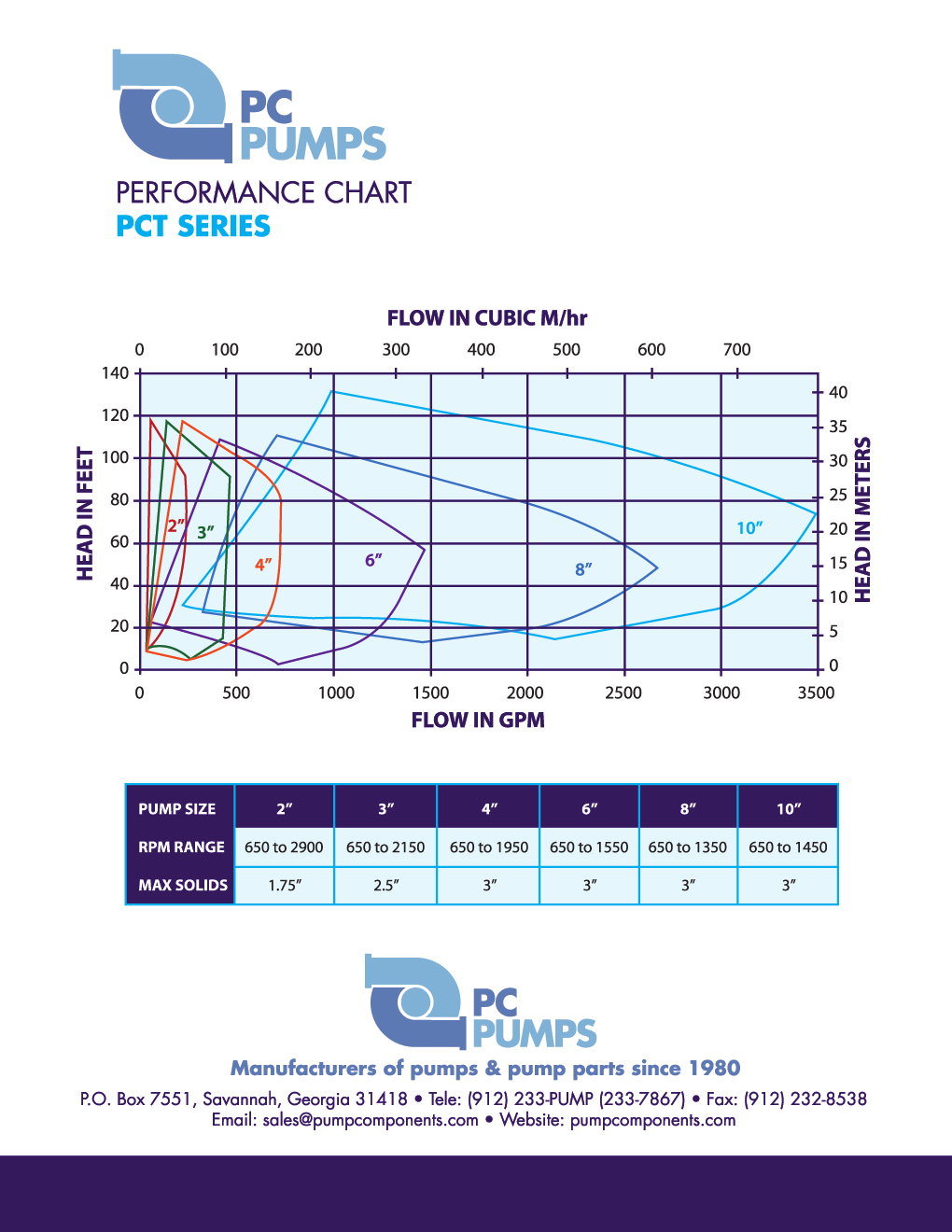
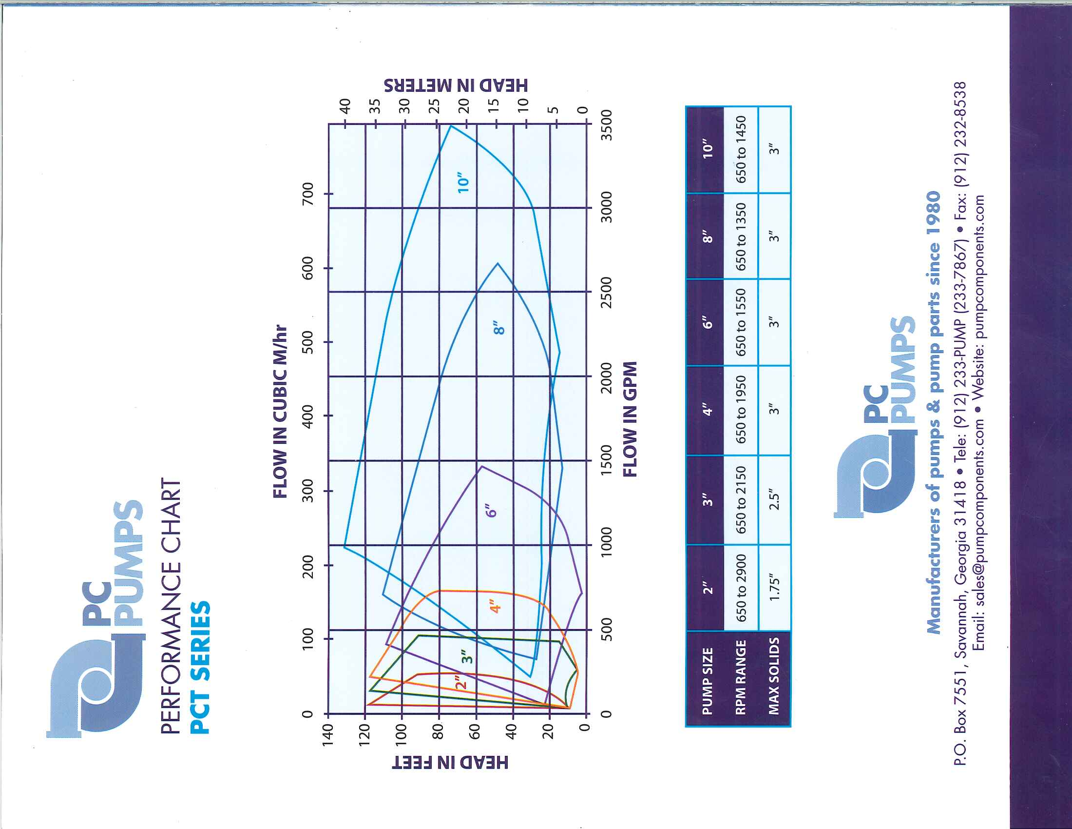
24 VARIABLE SPEED PERFORMANCE CURVE MODEL PCT2A, 6.25 OD 2 VANE IMPELLER

25 VARIABLE SPEED PERFORMANCE CURVE MODEL PCT3A, 8.75 OD 2 VANE IMPELLER

26 VARIABLE SPEED PERFORMANCE CURVE MODEL PCT4A, 9.75 OD 2 VANE IMPELLER

27 VARIABLE SPEED PERFORMANCE CURVE MODEL PCT6A, OD 2 VANE IMPELLER

28 VARIABLE SPEED PERFORMANCE CURVE MODEL PCT8A, OD 2 VANE IMPELLER

29 VARIABLE SPEED PERFORMANCE CURVE MODEL PCT10A, OD 2 VANE IMPELLER
Owner s Manual. Models: 2S5P & 3S5P OPERATION AND MAINTENANCE OF SELF-PRIMING CENTRIFUGAL TRASH PUMPS PEDESTAL DRIVE
 Owner s Manual Models: 2S5P & 3S5P OPERATION AND MAINTENANCE OF SELF-PRIMING CENTRIFUGAL TRASH PUMPS PEDESTAL DRIVE WARNING!! Installation & Operating Instructions Self-Priming Centrifugal Pump DO NOT
IMPORTANT SAFETY NOTICE
 IMPORTANT SAFETY NOTICE To: Our Valued Customers User safety is a major focus in the design of our products. Following the precautions outlined in this manual will minimize your risk of injury. ITT Goulds
Industrial Process Pump Safety Manual IMPORTANT SAFETY NOTICE
 Industrial Process Pump Safety Manual IMPORTANT SAFETY NOTICE To: Our Valued Customers User safety is a major focus in the design of our products. Following the precautions outlined in this manual will
BOWIE PUMPS OPERATION - MAINTENANCE
 BOWIE PUMPS OPERATION - MAINTENANCE PUMPING PRINCIPLE: The meshing owieeof the gears cause a slight depression, with the resulting enmeshing of the gears causing a vacuum drawing the fluid being pumped
OPERATION & MAINTENANCE MANUAL. for VERTICAL INLINE PUMPS
 OPERATION & MAINTENANCE MANUAL for VERTICAL INLINE PUMPS PATTERSON PUMP COMPANY A SUBSIDIARY OF THE GORMAN-RUPP COMPANY PO Box 790 9201 Ayersville Road Toccoa, Georgia 30577 Telephone: 706-886-2101 SAFETY
2" & 3" Poly Wet Seal Pump Instruction Manual
 Always place the pump as close to the liquid to be pumped as possible. Keep the suction line short and with few bends. Keep the pump and engine on a level foundation. A poor foundation and a heavy suction
MODEL 341A SINGLE STAGE END SUCTION PUMPS
 MODEL 44A MODEL 42A MODEL 41A MODELS 41A, 42A and 44A SINGLE STAGE END SUCTION PUMPS INSTRUCTION AND REPAIR MANUAL NOTE! To the installer: Please make sure you provide this manual to the owner of the equip
Trash Pumps Models: 56200, 562000, 56201, 562001, 56300, 563000, 56301, 563001
 Trash Pumps Models: 56200, 562000, 56201, 562001, 56300, 563000, 56301, 563001 Specifically designed pumps for heavy duty applications Handles solids with eas and simple to open and clean Standard roll
TECHNICAL SERVICE MANUAL
 TECHNICAL SERVICE MANUAL HEAVY-DUTY PUMPS SERIES 4195 AND 495 SIZES GG - AL SECTION TSM 144 PAGE 1 of 10 ISSUE D CONTENTS Introduction....................... 1 Safety Information.................... 2
SINGLE STAGE INLINE FIRE PUMP
 MODEL 383 SINGLE STAGE INLINE FIRE PUMP INSTRUCTION AND REPAIR MANUAL NOTE! To the installer: Please make sure you provide this manual to the owner of the equip ment or to the responsible party who maintains
STEERING SYSTEM - POWER
 STEERING SYSTEM - POWER 1990 Nissan 240SX 1990 STEERING Nissan - Power Rack & Pinion Axxess, Maxima, Pulsar NX, Sentra, Stanza, 240SX, 300ZX DESCRIPTION The power steering system consists of a rack and
GT Horizontal Split Casing Pumps
 GT Horizontal Split Casing Pumps 302-054 Operations and Maintenance Manual SUPERSEDES: New EFFECTIVE: March 1, 2009 Plant ID No. 001-3930 SAFETY REQUIREMENTS These operating instructions must be complied
300 SERIES 331, 332, 333, 344, 356 AND 367 MODELS
 Section: MOYNO 500 PUMPS Page: 1 of 8 Date: March 1, 1998 SERVICE MANUAL MOYNO 500 PUMPS 300 SERIES 331, 332, 333, 344, 356 AND 367 MODELS Mechanical Seal Models Packing Gland Models MODELS DESIGN FEATURES
HYDRAULIC LIFT TABLE CART 2200-LB.
 HYDRAULIC LIFT TABLE CART 2200-LB. OWNER S MANUAL WARNING: Read carefully and understand all MACHINE ADJUSTMENT AND OPERATION INSTRUCTIONS before operating. Failure to follow the safety rules and other
SE-100-1, SE-200-1, SE-500-1, and SE-1000-1 AIR CHAMP PRODUCTS. User Manual SE BRAKE MODELS: (i) MTY (81) 83 54 10 18 ventas@industrialmagza.
 MTY (81) 83 54 10 18 ventas@industrialmagza.") AIR CHAMP PRODUCTS User Manual SE BRAKE MODELS: SE-00-, SE-200-, SE-500-, and SE-000- (i) FORM NO. L-20084-E-040 In accordance with Nexen s established policy of constant product improvement, the specifications
AIR CHAMP PRODUCTS User Manual SE BRAKE MODELS: SE-00-, SE-200-, SE-500-, and SE-000- (i) FORM NO. L-20084-E-040 In accordance with Nexen s established policy of constant product improvement, the specifications
2100 AD 015 0009 Mirror Elevator Ball Nut Replacement Procedure
 2100 AD 015 0009 Mirror Elevator Ball Nut Replacement Procedure Derek Guenther 1/28/2015 Rev. Purpose The purpose of this document is to describe the procedure necessary to replace one of the ball nuts
Volkswagen New Beetle 2.0 Liter 4-cyl General, Engine (Engine Code AEG) 17 Engine-Lubrication system (Page GR-17)
 17 Engine-Lubrication system (Page GR-17)") 17 Engine-Lubrication system (Page GR-17) Lubrication system components, removing and installing Oil pan, removing and installing Oil pressure and oil pressure switch, checking Dynamic oil pressure warning
17 Engine-Lubrication system (Page GR-17) Lubrication system components, removing and installing Oil pan, removing and installing Oil pressure and oil pressure switch, checking Dynamic oil pressure warning
FJ2. 2 Ton Trolley Floor Jack Assembly & Operating Instructions
 FJ2 2 Ton Trolley Floor Jack Assembly & Operating Instructions READ ALL INSTRUCTIONS AND WARNINGS BEFORE USING THIS PRODUCT. This manual provides important information on proper operation & maintenance.
STORAGE, INSTALLATION AND MAINTENANCE PROCEDURES
 GATE VALVE O.S. & Y 1.0 Periodic Inspections 1.1 The valve stem packing should be inspected at least monthly. If the stem packing shows signs of leakage, simply tighten the adjusting nuts to compress the
Constantemp Double Wall Low pressure steam-water Heater F-340LDW,F-640LDW, F-940LDW and F-1240LDW
 Installation, Operating and Maintenance Instructions 90/4.5.5 Rev. 0 Constantemp Double Wall Low pressure steam-water Heater F-340LDW,F-640LDW, F-940LDW and F-1240LDW Table of Contents SECTION I... 2 INSTALLATION...
Rexroth Hydraulic Pump A10VO Series User Manual
 Rexroth Hydraulic Pump A10VO Series User Manual Rexroth Hydraulic pump A10VO Series User Manual Revised 5/1/2009 Page 1 of 12 Functional Purpose This pump is preferred over a fixed displacement (gear)
Important: Please read these instructions carefully and completely before starting the installation. TITAN Fuel Tanks
 TITAN pt. no.: 03 0000 0120 Important: Please read these instructions carefully and completely before starting the installation. TITAN Fuel Tanks INSTALLATION INSTRUCTIONS G e n e r a t i o n V Extended
Float and Thermostatic Traps Series H, C and X
 Hoffman Specialty Installation & Maintenance Instructions HS-(E) and Thermostatic Traps Series H, C and X Series C & NPT Series C NPT Series X NPT Series C NPT Series H Ratings Maximum Max. Operating NPT
VERTICAL AND HORIZONTAL END SUCTION PUMPS INSTALLATION, OPERATION AND MAINTENANCE MANUAL
 GUSHER PUMPS, INC. 115 INDUSTRIAL DRIVE WILLIAMSTOWN, KY 41097 PHONE: 859-824-3100 FAX: 859-824-7428 www.gusher.com VERTICAL AND HORIZONTAL END SUCTION PUMPS INSTALLATION, OPERATION AND MAINTENANCE MANUAL
TWO-STAGE CENTRIFUGAL PUMPS
 MODELS I2C and I2CI/2C95 TWO-STAGE CENTRIFUGAL PUMPS INSTALLATION AND SERVICE MANUAL NOTE! To the installer: Please make sure you provide this manual to the owner of the equip ment or to the responsible
OPERATING AND MAINTENANCE INSTRUCTIONS PUMP TYPE 215.10
 OPERATING AND MAINTENANCE INSTRUCTIONS PUMP TYPE 215.10 To Pump model Pump number Our order Your order Order date Reference Item number Destination Plant Before storing, installation, operation or maintenance
Installation and Operating Instructions Installation Instructions for SS EPE-316L Series
 INSTR3010 0406 Installation and Operating Instructions Installation Instructions for SS EPE-316L Series Congratulations on your purchase of this Aqua-Pure high flow, single housing filtration system. This
SunMaxx Solar Filling Station Operating Instructions
 SunMaxx Solar Filling Operating Instructions Content 1. Declaration of conformity... 2 2. Introduction... 2 3. Transportation and unpacking... 4 4. Mounting and commissioning... 5 5. End of operation...
SERIES HYDRAULIC MOTOR DRIVEN CENTRIFUGAL PUMPS
 INSTRUCTION MANUAL OASIS WetSeal Technology T M MAX SERIES HYDRAULIC MOTOR DRIVEN CENTRIFUGAL PUMPS 1 2 TABLE OF CONTENTS Pump performance data, dimensions, and part listings are on individual pump specification
DODGE USAF 200/300 Direct Mount Pillow Block Bearings
 DODGE USAF 200/300 Direct Mount Pillow Block Bearings These instructions must be read thoroughly before installation or operation. WARNING: To ensure that drive is not unexpectedly started, turn off and
DeZURIK 3-20" BAW AWWA BUTTERFLY VALVES WITH TRANSFER MOLDED SEAT
 3-20" BAW AWWA BUTTERFLY VALVES WITH TRANSFER MOLDED SEAT Instruction D10386 August 2013 Instructions These instructions provide installation, operation and maintenance information for BAW Butterfly Valves.
TITAN Fuel Tanks. INSTALLATION INSTRUCTIONS G e n e r a t i o n V
 TITAN pt. no.: 02 0000 0143 Important: Please read these instructions carefully and completely before starting the installation. TITAN Fuel Tanks INSTALLATION INSTRUCTIONS G e n e r a t i o n V Extended
Volkswagen Jetta, Golf, GTI 1999, 2000 2.8 Liter VR6 2V Engine Mechanical, Engine Code(s): AFP 17 Engine-Lubrication (Page GR-17)
: AFP 17 Engine-Lubrication (Page GR-17)") 17 Engine-Lubrication (Page GR-17) Lubrication system components, removing and installing Oil filter housing, disassembling and assembling Oil pan, removing and installing Oil pressure and oil pressure
17 Engine-Lubrication (Page GR-17) Lubrication system components, removing and installing Oil filter housing, disassembling and assembling Oil pan, removing and installing Oil pressure and oil pressure
Oil and Coolant Circulating Heating System. Model - OCSM
 Oil and Coolant Circulating Heating System Model - OCSM Installation & Operation Manual 216280-000 REV 2 Identifying Your System The HOTSTART heating system is designed to heat fluids for use in marine
Pump Maintenance - Repair
 Pump Maintenance - Repair Brian Trombly Mo Droppers Cummins Bridgeway, Gaylord, Mi The basic centrifugal pump consists of two main elements: 1. The rotating element which includes an impeller and a shaft.
IF IT FLOWS THE BOWIE PUMP CAN PUMP IT
 IF IT FLOWS THE BOWIE PUMP CAN PUMP IT Bowie Industries, Inc. Bowie, TX 76230 USA Page 1 Bowie Pumps Manual General Pump Information..Page 2 300 Series Pumps.. Page 5 400 Series Pumps.Page 11 500 Series
Installation, Operation, Repair and Parts Manual
 Description Series 9700 Close-Coupled AC Motor-Driven and Pedestal Mount Centrifugal Pumps Installation, Operation, Repair and Parts Manual Form L-0350C Rev. B Hypro's 9700 series pumps are specifically
Series 1510 and 1510/Universal Centrifugal Pumps
 Bell & Gossett INSTRUCTION MANUAL P81673 REVISION F Series 1510 and 1510/Universal Centrifugal Pumps Installation, Operation and Service Instructions INSTALLER: PLEASE LEAVE THIS MANUAL FOR THE OWNER S
758 Heavy-duty Ratchet Guy Wire Cutter
 INSTRUCTION MANUAL 758 Heavy-duty Ratchet Guy Wire Cutter Read and understand all of the instructions and safety information in this manual before operating or servicing this tool. Register this product
HYDRAULIC TABLE CART 500-LB.
 HYDRAULIC TABLE CART 500-LB. OWNER S MANUAL WARNING: Read carefully and understand all MACHINE ADJUSTMENT AND OPERATION INSTRUCTIONS before operating. Failure to follow the safety rules and other basic
Installation and Start-up Instruction
 Screw pumps Low pressure pumps Installation and Start-up Instruction This instruction is valid for all standard low pressure pumps: LD, ACD, ACE, LE, ACG/UCG, ACF/UCF, LQ and AQ Contents age ump identification
Instructions and precautions. Fork Height. Visit our website at: http://www.harborfreight.com
 Pallet Jack Item 68760 / 68761 Instructions and precautions Specifications Capacity Control Lever Fork Height Fork Length Fork Width Maximum Minimum Width over Forks Steering Wheel Dia. 2-1/2 Ton (5,000
White Industries Rear Hub Instructions
 White Industries Rear Hub Instructions Tool required: 2mm allen/hex wrench, 19mm socket, 20mm socket, and mallet. 1. Loosen the set screws located in the adjusting collar by using a 2mm allen wrench inserted
1.8 CRANKSHAFT OIL SEALS
 SERIES 60 SERVICE MANUAL 1.8 CRANKSHAFT OIL SEALS An oil seal is fitted between each end of the crankshaft and the bores of the flywheel housing and gear case cover to retain the lubricating oil in the
Table of Contents. Overview 1. Pump Disassembly 2. Control Disassembly / Reassembly 7. Pump Reassembly 13. Adjustment Procedures DR Control 19
 Table of Contents Overview 1 Pump Disassembly 2 Control Disassembly / Reassembly 7 Pump Reassembly 13 Adjustment Procedures DR Control 19 Adjustment Procedures DRG Control 20 Adjustment Procedures DFR
P7100 PUMP INSTALLATION INSTRUCTIONS Diesel Care & Performance Inc
 P7100 PUMP INSTALLATION INSTRUCTIONS Diesel Care & Performance Inc Installation Timing Pin Location CAUTION: Before installing the injection pump, be sure that number 1 cylinder is at the Top Dead Center
Char-Lynn Hydraulic Motor. Repair Information. 10 000 Series. October, 1997
 Char-Lynn Hydraulic Motor October, 1997 Repair Information Geroler Motor Two Speed 001 27 Retainer inside bore of valve plate bearingless motors only 4 15 16 3 6 35 Parts Drawing 25 2 2 1 19 17 36 40 47
OP300S / OP350 2:1 RATIO TRANSFER PUMP
 OP300S / OP350 2:1 RATIO TRANSFER PUMP OPERATING MANUAL WITH PARTS IDENTIFICATION Copyright 2013 International Pump Manufacturing, Inc. This manual contains IMPORTANT WARNINGS and INSTRUCTIONS. Read and
OWNER S MANUAL Table Tennis Table Patent Pending
 OWNER S MANUAL Table Tennis Table Patent Pending Be sure to write your model number and serial number here for future reference. You can find these numbers printed on the bottom of the table. MODEL # T8179
Model 854/856. Operating and Assembly Manual. Palmor Products Inc. 5225 Serum Plant Road Thorntown, IN 46071
 Model 854/856 Operating and Assembly Manual Palmor Products Inc. 55 Serum Plant Road Thorntown, IN 46071 3/31/2015 SAFETY RULES Remember, any power equipment can cause injury if operated improperly or
INSTALLATION & OPERATING INSTRUCTIONS
 INSTALLATION & OPERATING INSTRUCTIONS WARNING RISK OF ELECTRIC SHOCK. CONNECT ONLY TO A CIRCUIT PROTECTED BY A GROUND-FAULT CIRCUIT-INTERRUPTER. THE UNIT SHOULD BE INSTALLED BY A QUALIFIED SERVICE REPRESENTATIVE.
CORNELL PUMPS IRRIGATION FOOD MUNICIPAL PROCESS INDUSTRIAL
 EFFICIENT BY DESIGN Installation & Care of PUMPS IRRIGATION FOOD MUNICIPAL PROCESS INDUSTRIAL Cornell Pump Company P.O. Box 6334 Portland, Oregon 97228 Phone: (503) 653-0330 Fax: (503) 653-0338 Web: www.cornellpump.com
ELECTRIC/DIESEL FIRE PUMP CHECK LIST
 BUILDING NAME: DESIGNER: SCO REPRESENTATIVE: PUMP MANUF.: LOCATION: INSTALLER: DATE: OWNER NAME: INSTALLATION Certificate for flushing and hydrostatic test furnished Piping been hydrostatically tested
These features have made Lo Torc valves the choice of high pressure plug value users, worldwide:
 LO TORC Plug Valve The high value, dependable performance, and low maintenance requirements of Halliburton Lo Torc valves can help reduce overall operating costs and help cut downtime. These features have
Fisher 1061 Pneumatic Piston Rotary Actuator with Style F & G Mounting Adaptations
 Instruction Manual 1061 F & G Actuator Fisher 1061 Pneumatic Piston Rotary Actuator with Style F & G Mounting Adaptations Contents Introduction... 1 Scope of Manual... 1 Description... 2 Specifications...
PBX Series Quick Fit Connector Bimetallic Steam Traps
 6262100/6 IM-P626-01 ST Issue 6 PBX Series Quick Fit Connector Bimetallic Steam Traps Installation and Maintenance Instructions 1. Safety information 2. General product information 3. Installation 4. Commissioning
MASTER APG C-FACE AND SEPARATE REDUCERS
 INSTRUCTION MANUAL 499983 MASTER APG C-FACE AND SEPARATE REDUCERS INSTALLATION AND PARTS FOR APG SIZE 1 For APG Sizes 2 through 8, refer to manual 499972 WARNING: Because of the possible danger to person(s)
PUMPS TYPE OF PUMP PRESSURE/FLOW RATING CHARACTERISTICS. Centrifugal Low Pressure/High Flow Flow changes when
 PUMPS Pumps provide the means for moving water through the system at usable working pressures. The operation and maintenance of these pumps are some of the most important duties for many water utility
KS Vertical In-Line Pump
 KS Vertical In-Line Pump 302-032 Installation, Operation & Maintenance Manual SUPERSEDES: July 1, 2010 EFFECTIVE: August 1, 2012 Plant ID No. 001-1014 SAFETY REQUIREMENTS 1. IMPORTANT! These instructions
TOPIC: 191004 KNOWLEDGE: K1.01 [3.3/3.5] Which one of the following contains indications of cavitation in an operating centrifugal pump?
![TOPIC: 191004 KNOWLEDGE: K1.01 [3.3/3.5] Which one of the following contains indications of cavitation in an operating centrifugal pump?](/thumbs/17/105210.jpg "TOPIC: 191004 KNOWLEDGE: K1.01 [3.3/3.5] Which one of the following contains indications of cavitation in an operating centrifugal pump?") KNOWLEDGE: K1.01 [3.3/3.5] P21 Which one of the following contains indications of cavitation in an operating centrifugal pump? A. Low flow rate with low discharge pressure. B. Low flow rate with high discharge
KNOWLEDGE: K1.01 [3.3/3.5] P21 Which one of the following contains indications of cavitation in an operating centrifugal pump? A. Low flow rate with low discharge pressure. B. Low flow rate with high discharge
MODEL G300 BRAKE BLEEDER
 MODEL G300 BRAKE BLEEDER Installation, Operation & Repair Parts Information Branick Industries, Inc. 4245 Main Avenue P.O. Box 1937 Fargo, North Dakota 58103 REV060616 P/N: 81-0035G 1 THIS PAGE INTENTIONALLY
HYBRID CAM PLATE AND HIGH VOLUME OIL PUMP KIT
 -J056 REV. 0-05-0 HYBRID CAM PLATE AND HIGH VOLUME OIL PUMP KIT GENERAL Kit Number 584- Models For model fitment information, see the P&A retail catalog or the Parts and Accessories section of www.harley-davidson.com
Fluid Regulator. Instructions Parts List 306563L LOW PRESSURE
 Instructions Parts List LOW PRESSURE Fluid Regulator 306563L For accurate, positive control of fluid pressure to one spray gun, dispensing valve, or atomizing head. For professional use only. 250 psi (18
Chapter 7 Hydraulic System Troubleshooting
 Chapter 7 Hydraulic System Troubleshooting General The following troubleshooting information is provided as a general guide to identify, locate and correct problems that may be experienced with the hydraulic
Char-Lynn Spool Valve Hydraulic Motors. Repair Information. W Series Geroler Motors
 Char-Lynn Spool Valve Hydraulic Motors Repair Information W Series Geroler Motors with Parking Brake 004 Nut Key Ring, Retaining Bearing Ring, Retaining Ring, Retaining Washer (Thick), Pressure Washer,
Operation & Maintenance Manual
 Manual # OMAV2-SUMP1 High Performance Air & Dirt Separators Manual # 9636-1230 Rev. A Operation & Maintenance Manual 340 West 8 th Street Peru, IN 46970 PH: 765 472 3351 FX: 765 472 3968 www.thrushco.com
MP-4V Heavy Duty Riveter / 39048
 MP-4V Heavy Duty Riveter / 39048 This newly designed heavy-duty air/hydraulic riveter is ergonomically designed with the professional in mind. The light weight 3.7 lbs. well balanced MP-4V includes a Vacuum
Spicer Axles & Brakes ABIB-0302
 Information Bulletin Bulletin Type: Parts / Service Information Topic: Dana LMS Hub Assembly Procedure Steer and Drive Axles Spicer Axles & Brakes ABIB-0302 Note: Bulletin ABIB-0302 replaces the original
Rating when used as a weight carrying hitch without spring bars:
 BOLT-TOGETHER WEIGHT DISTRIBUTING HITCH SYSTEM Rating when used as a weight distributing hitch with spring bars: Part Number 48051 4805 48053 48054 Max Tongue Weight 550 Ibs. 750 Ibs. 1000 Ibs. 1400 lbs.
OPERATION & MAINTENANCE MANUAL. for 5 X 3 MAC - 5 X 4 MAC DOUBLE SUCTION SPLIT CASE PUMPS
 OPERATION & MAINTENANCE MANUAL for 5 X 3 MAC - 5 X 4 MAC DOUBLE SUCTION SPLIT CASE PUMPS PATTERSON PUMP COMPANY A SUBSIDIARY OF THE GORMAN-RUPP COMPANY PO Box 790 9201 Ayersville Road Toccoa, Georgia 30577
This instruction is valid for all ACD pump models shown on page 2
 Screw pumps ACD Maintenance and Service Instruction This instruction is valid for all ACD pump models shown on page 2 Contents Page List of components 2 Exploded view/ordering code 3 Service intervals
SELF-STEERING AXLE TABLE OF CONTENTS
 SELF-STEERING AXLE TABLE OF CONTENTS Section 1 - Introduction Section 2 - Pre-Installation Check List Section 3 - Ride Height Adjustments Section 4 - Suspension Mount Section 5 - Axle Mount Section 6 -
BICO CHIPMUNK JAW CRUSHER - TYPE WD
 BICO CHIPMUNK JAW CRUSHER - TYPE WD The Bico Chipmunk Jaw Crusher is designed to give long and efficient service. In order to secure the long life and excellent performance that your crusher is capable
Strut Spring Compressor
 Strut Spring Compressor Item 43753 Read this material before using this product. Failure to do so can result in serious injury. SAVE THIS MANUAL. When unpacking, make sure that the product is intact and
MSD Pro-Billet Ready-to-Run Chevrolet V8 Distributor, PN 8360 Chevrolet 348, 409 Distributor, PN 8393
 MSD Pro-Billet Ready-to-Run Chevrolet V8 Distributor, PN 8360 Chevrolet 348, 409 Distributor, PN 8393 ONLINE PRODUCT REGISTRATION: Register your MSD product online and you ll be entered in our monthly
Installation, Operating and Maintenance Instructions for AEON Metal Seated Gate Valve (MSGV) Water
 Water") 1 Foreword 1.1 Thank you for choosing one of the range of AEON's BS standard valves. For safety purposes, the user shall read this instruction to fully understand the operation of the product. 2 AEON Design
1 Foreword 1.1 Thank you for choosing one of the range of AEON's BS standard valves. For safety purposes, the user shall read this instruction to fully understand the operation of the product. 2 AEON Design
Stainless Steel Single and Dual Circulation Kits
 Instruction Sheet P/N 160780 01 Stainless Steel Single and Dual Circulation Kits Introduction The single and dual high-pressure circulation kits allow you to vary and control the circulation rate of coating
TUTORIAL. REbUILdING. front CALIpER O-RING CONVERSION CORVETTE 1965-82. Part #: HT-1
 Part #: HT-1 1965-82 CORVETTE O-RING CONVERSION front CALIpER REbUILdING TUTORIAL Choosing a Brake Caliper Rebuild Kit Standard Lip Seals vs. O-Ring Seals Lip seal design seals are used on 1965-1982 Corvette
Overview PARTS LIST. B. Lever mounting base C. Flush handle assembly D. Grey/Blue float stop E. Grey float (Full Flush) F. Flush valve washer
 F. Flush valve washer") Overview READ ENTIRE INSTRUCTIONS BEFORE STARTING INSTALLATION PARTS LIST A. Flush valve B. Lever mounting base C. Flush handle assembly D. Grey/Blue float stop E. Grey float (Full Flush) F. Flush valve
Overview READ ENTIRE INSTRUCTIONS BEFORE STARTING INSTALLATION PARTS LIST A. Flush valve B. Lever mounting base C. Flush handle assembly D. Grey/Blue float stop E. Grey float (Full Flush) F. Flush valve
WHAT YOU DON T KNOW ABOUT ACCUMULATORS CAN KILL YOU!
 WHAT YOU DON T KNOW ABOUT ACCUMULATORS CAN KILL YOU! Atlanta (Monroe) GA 770-267-3787 gpm@gpmhydraulic.com www.gpmhydraulic.com What You Don t Know About Hydraulic Accumulators Can Kill You TABLE OF CONTENTS
ASSEMBLY DIAGRAM AND ASSEMBLY REFERENCE ULTIMA OLD SCHOOL 2 EVO & TC BELT DRIVE UNITS
 ASSEMBLY DIAGRAM AND ASSEMBLY REFERENCE ULTIMA OLD SCHOOL 2 EVO & TC BELT DRIVE UNITS BELT DRIVE ASSEMBLIES Part# 58-850 2 Old School Belt Drive Assembly - Polished Part# 58-851 2 Old School Belt Drive
SELF-PRIMING CENTRIFUGAL PUMPS
 PUBLICATION NUMBER December 2, 1998 Rev. A 11-20-03 SELF-PRIMING CENTRIFUGAL PUMPS THE GORMAN-RUPP COMPANY D MANSFIELD, OHIO GORMAN-RUPP OF CANADA LIMITED D ST. THOMAS, ONTARIO, CANADA Printed in U.S.A.
TROUBLESHOOTING GUIDE
 RJS SELF-PRIMING SHALLOW WELL JET PUMPS a. Motor will not start: 1. No power to pressure switch due to blown fuses, open switches or loose connections. 2. Pump pressure switch not closed. b. Pump fails
IEC Three Phase AC Motors (Aluminum Frame) Installation & Operating Manual
 Installation & Operating Manual") IEC Three Phase AC Motors (Aluminum Frame) Installation & Operating Manual 7/09 MN301 Table of Contents Section 1 General Information.................................................. 1-1 Overview........................................................
IEC Three Phase AC Motors (Aluminum Frame) Installation & Operating Manual 7/09 MN301 Table of Contents Section 1 General Information.................................................. 1-1 Overview........................................................
DiscPlus DX195 and DX225 Air Disc Brakes
 Revised 11-04 Technical Bulletin Revised 1 Technical 11-04 Bulletin DiscPlus DX195 and DX225 Air Disc Brakes Inspection, Installation and Diagnostics Air Disc Brake Inspection Intervals and Procedures
MODEL 300505 INSTALLATION INSTRUCTIONS
 WWW.BURCAM.COM 2190 Boul. Dagenais West TEL: 514.337.4415 LAVAL (QUEBEC) FAX: 514.337.4029 CANADA H7L 5X9 info@burcam.com Your pump has been carefully packaged at the factory to prevent damage during shipping.
Engine, disassembling and assembling
 13-1 Engine, disassembling and assembling Note: Replace the oil cooler and thoroughly clean the oil passages if you find metal shavings or larger quantities of small metal particles in the engine oil,
Extrusion Flo-Valve INSTRUCTIONS-PARTS LIST. 3000 psi (210 bar) Maximum Working Pressure. Model 204 355, Series K. Rev.
 Maximum Working Pressure. Model 204 355, Series K. Rev.") INSTRUCTIONS-PARTS LIST INSTRUCTIONS This manual contains important warnings and information. READ AND KEEP FOR REFERENCE. 306 586 Rev. D Supercedes B Extrusion Flo-Valve Model 204 355, Series K 3000 psi
INSTRUCTIONS-PARTS LIST INSTRUCTIONS This manual contains important warnings and information. READ AND KEEP FOR REFERENCE. 306 586 Rev. D Supercedes B Extrusion Flo-Valve Model 204 355, Series K 3000 psi
Step by Step Procedure for Removal or Repair of Pump Components on Subaru Robin Pumps (This Includes Mechanical Seal Replacement
 SERVICE MANUAL Models PTG109, PKV101, PKX201H, PKX201, PKX301, PKX201T, PKX301T, PKX201ST, PKX301ST Step by Step Procedure for Removal or Repair of Pump Components on Subaru Robin Pumps (This Includes
CENTRIFUGAL PUMP OVERVIEW Presented by Matt Prosoli Of Pumps Plus Inc.
 CENTRIFUGAL PUMP OVERVIEW Presented by Matt Prosoli Of Pumps Plus Inc. 1 Centrifugal Pump- Definition Centrifugal Pump can be defined as a mechanical device used to transfer liquid of various types. As
TECHNICAL BROCHURE B5-33GB 5GB, 7GB, 10GB, 18GB, 25GB, 33GB HIGH PRESSURE MULTI-STAGE BOOSTER PUMP
 TECHNICAL BROCHURE B-33GB GB, 7GB, 1GB, 18GB, 2GB, 33GB HIGH PRESSURE MULTI-STAGE BOOSTER PUMP FEATURES Multi-stage Design: Provides steady, quiet, vibration free, operation. Optional Stainless Steel Construction:
Dive Rite 200 & 300 Bar Isolator Manifold Service Manual
 Dive Rite 200 & 300 Bar Isolator Manifold Service Manual Principal Photography and Text by Pete Nawrocky Copyright 2003 Lamartek Inc. D/B/A Dive Rite 0 Warning This manual is only to be used as a guide
Voltmaster Trash Pumps Model TSP2, TSP3 and TSP4
 Model TSP2, TSP3 and TSP4 Owner s Manual July 2010 Table of Contents 1 Introduction...................................................... 1 1.1 Read before using..............................................
OPERATION AND MAINTENANCE MANUAL 5-1/4 B-84-B-5 FIRE HYDRANT
 OPERATION AND MAINTENANCE MANUAL 5-1/4 B-84-B-5 FIRE HYDRANT INDEX AMERICAN - DARLING 5-1/4 IN. B-84-B-5 FIRE HYDRANT OPERATION AND MAINTENANCE MANUAL OPERATION AND MAINTENANCE REPAIRS Operation and Maintenance...
CHAPTER 65 TAIL ROTOR DRIVE SYSTEM. Section Title Page
 CHAPTER 65 TAIL ROTOR DRIVE SYSTEM Section Title Page 65-00 Description........................................ 65.1 65-10 Tail Rotor Drive Fan Shaft.............................. 65.1 65-20 Tail Rotor
Read This First! OWNER S GUIDE
 MOBILE MASTERCOOL OWNER S GUIDE Read This First! CAUTION Read all instructions carefully before setting up and operating this unit! This manual was designed to provide you with important information needed
ALIGNMENT. Pump and Driver Alignment
 ALIGNMENT Pump and Driver Alignment Alignment Subject: Pump and Driver Alignment In the pump business alignment means that the centerline of the pump is aligned with the centerline of the driver. Although
Premier & Deluxe 3-Season Room Sliding Glass Door
 DTSSGD-11 Premier & Deluxe 3-Season Room Sliding Glass Door Installation Instructions Screen Door Seal Left Side Track Top Track Assembly Right Side Track Right Side Trim Sliding Glass Door Sliding Screen
PARTS LIST OPERATING AND SERVICE MANUAL
 GARDNER DENVER TUL-C-600 Rev A January, 2005 CENTRIFUGAL PUMPS 4 x 5 and 5 x 6 PARTS LIST OPERATING AND SERVICE MANUAL ECN 1024021 MAINTAIN PUMP RELIABILITY AND PERFORMANCE WITH GENUINE GARDNER DENVER
Table of Contents WARNING SYMBOLS AND DEFINITIONS
 Table of Contents SAFETY INSTALLATION OPERATION MAINTENANCE Safety... 2 Specifications... 4 Installation... 5 Operation... 8 WARNING SYMBOLS AND DEFINITIONS Maintenance... 9 Parts List and Assembly Diagram...