Operation and Maintenance Manual of WP13C Series Diesel Engines
|
|
|
- Kenneth Byrd
- 7 years ago
- Views:
Transcription

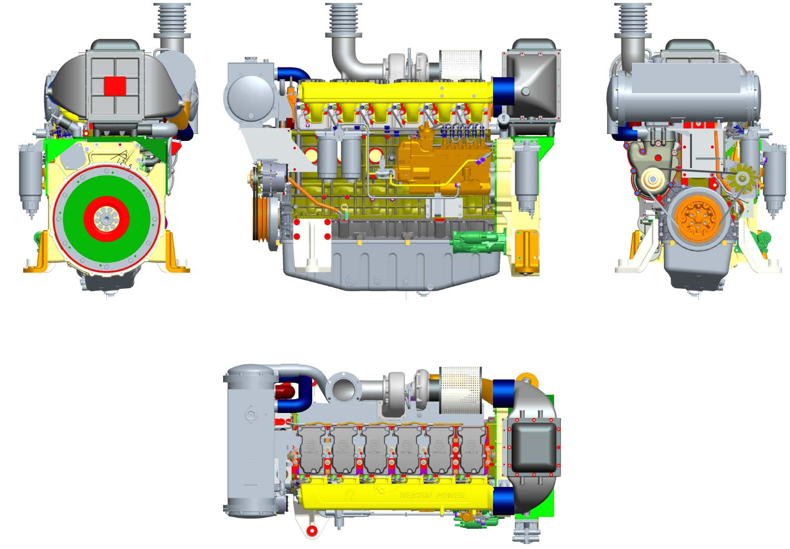
1 Operation and Maintenance Manual of WP13C Series Diesel Engines Weichai Power Co., Ltd
2 In order to protect your legitimate rights, it is prohibited to unseal the lead seal of fuel pump by yourself. If you adjust the fuel injection pump or remove the lead seal, the warranty will be invalid. The fuel injection pump and the fuel injector are precise parts, and users shall not disassemble them. Otherwise, the warranty will be invalid. The supercharger rotor shaft is of precise and high speed rotating part, it is prohibited to disassemble or collide it. Otherwise, the warranty will be invalid. The main bearing bolts and connecting rod bolts of diesel engine have strict requirements on torque and rotation angle, users shall not loosen or remove them. Otherwise, the warranty will be invalid. Every time before operating the engine, check whether the coolant and the oil are sufficient. The connecting rod bolts are disposable bolts, do not reuse them.
3 1. Please note that before delivery, the diesel engine is already tested strictly according to the test specification, and the accelerator is lead sealed for limit. Do not remove the lead seal, increase the throttle, otherwise, we will not provide the three guarantees services. 2. The diesel engine operating personnel must read this Operation and Maintenance Manual carefully to get familiar with the structure and strictly observe the technical operation and maintenance regulations specified in the manual. 3. When the user uses the new diesel engine, carry out the test run for 50h. 4. After cold starting, increase the speed of diesel engine slowly, do not run it at high speed sharply or idle it without load for a long time. After heavy load running, do not stop immediately, run it at low speed without load for (5~10) min and then stop. 5. After stopping, if the ambient temperature may be below 0 and there is no antifreeze additive, please drain the water in the water tank and the diesel engine. 6. Do not operate the diesel engine which is not equipped with an air filter, otherwise, the air may enter the cylinder without filtering 7. When adding oil or fuel added to the diesel engine, select the grade specified in the manual. Adopt a special cleaning container and filter the fuel or oil through the filter screen. Let the fuel precipitate for more than 72h. 8. Check and maintenance of all parts of the electrical system shall be carried out by personnel having good electrical knowledge. 9. Oil seal is carried out on the diesel engine before delivery in order to prevent rust. Generally speaking, the oil seal period of diesel engine is one year, carry out check and take necessary supplement measures when exceeding one year. 10. Do not run the diesel engine at idle speed for a long time, generally no more than 10min. 11. Please use the oil filter, diesel filter and air filter made by the manufacturers designated by our company. Otherwise, we will not provide the three guarantees service.
4 Foreword The WP13C series diesel engines are variant products of WP13 Landking series diesel engines. The design meets requirements of national standards and ship regulations. It is featuring reliable use, good economic and technology index, low emission, fast starting, simple operation and convenient maintenance, and are the ideal power for industrial power stations. This manual describes the WP13C series diesel engines in aspects of structure, performance, operation, test, operation and maintenance. With the continuous development of production and technology, the structure will be further improved, and users are reminded of the possible inconsistency between contents of this instruction and future improved contents. We sincerely hope that personnel operating and maintaining this diesel engine and other related personnel read this manual in advance and strictly observe the regulations to ensure correct and reasonable operation of the diesel engine and prolong the service life. During operation, if there is any problem, please do not hesitate to contact the after-sales service department of our company timely, and they will offer you prompt and considerate services. October, 2013
5 Contents Chapter I Main technical parameters of WP13C series... 2 diesel engines... 2 Chapter II Instruction on structure and systems of diesel... 3 engine Gear train and valve mechanism Lubricating system Fuel system Cooling system Electrical equipment... 8 Chapter IV Maintenance of WP13C series diesel engines Maintenance interval of WP13C series diesel engines Major works during diesel engine check and maintenance Daily maintenance of diesel engine Maintenance during long-term shutdown of diesel engine Operation requirements of diesel engine Chapter V Troubleshooting Chapter VI List of Wearing Parts of WP13C series diesel engines... 20
6 - 1 -
7 Chapter I Main technical parameters of WP13C series diesel engines 1. Technical parameters of WP13C450 diesel engine Table 1 Main technical parameters of WP13C450 diesel engine Model Type Number of cylinders bore stroke Rotation direction WP13C Inline, water-cooling, 4-stroke, direct injection, supercharged and inter-cooled Clockwise (watch from the free end) Firing order Fuel supply advance angle ºCA 15 ICXN (rated power-speed) ION (overload power-speed) Total displacement of piston L Minimum stable operating speed r/min 330kW-1800r/min 363kW-1858 r/min Idling speed r/min 650±50 Cold state valve clearance (mm) Intake valve 0.4; exhaust valve 0.6 Valve timing (valve clearance: intake valve 0.4mm, exhaust valve: 0.6mm) Starting manner Intake valve open 20 before top dead center Intake valve closed 34 after bottom dead center Exhaust valve open 49 before bottom dead center Exhaust valve closed 21 after top dead center Electric start Oil capacity L 36 Cooling manner Sea and fresh water circulation Overall dimensions mm Total mass kg
, in which the gear chamber and the flywheel housing are integrated in order to reduce the gear noise")
8 Chapter II Instruction on structure and systems of diesel engine 1.Gear train and valve mechanism 1.1 Gear train diagram The WP13C series diesel engines adopt the rear-mounted gear train (figure2-1), in which the gear chamber and the flywheel housing are integrated in order to reduce the gear noise and improve the overall reliability. 1.2 Valve clearance adjustment Fig.2-2 Cold state intake valve clearance 0.4mm Fig.2-3 Cold state exhaust valve clearance 0.6mm - 3 -
9 2.Lubricating system The lubricating system is functioned for wear reducing, flushing, cooling and rust proofing. Please use the oil of CI or higher grade. Multi-grade oil shall be preferably selected for better cold starting performance. Full-season multi-grade oil (such as 15W40) can also be used within the specified temperature scope. During occasional low temperature period, oil preheating measures can be taken or change the oil which is suitable for the environment temperature. The oil change intervals shall be determined according to maintenance requirements. Generally, the lubricating oil is not applied in delivery, so please apply it before starting the engine. Please select the viscosity grades (see table 2) of lubricating oil according to environment temperatures and only multi-grade lubricating oil is allowed. It is recommended that Weichai special lubricating oil be used. When the engine is stay still, the oil level shall be between the highest and lowest scale lines on the dipstick. Until now, there is no proof that the oil additives have any positive influence on running of WP13C mechanical pump series diesel engine, so it is prohibited to use any oil additives. Table 2 Lubricating oil grade selection Caution: For WP13C mechanical pump series diesel engine, it is not allowed to use grade CH and lower grade lubricating oil. Please replace the oil filter element every time when changing the oil! Pressure lubrication Through a strainer, the oil pump absorbs oil from the oil sump, press the oil to the oil filter and the oil cooler and then through the oil line system to the lubrication position. Most oil can reach the main bearing and through the oil hole on the crankshaft to the connecting rod bearing. The cylinder liner surface and the piston pin are lubricated by oil sprayed from nozzles. Lubrication of valve control system, supercharger, oil pump, air compressor and intermediate gear bearing is also realized by pressure lubrication through oil pipes and oil groove. The piston top is cooled by oil sprayed from nozzle to the internal cooled oil cavity; and oil is cooled by coolant through the oil cooler. The oil pressure of oil circulation system is adjusted by the pressure-limiting valve in the oil pump. When starting the diesel engine, as the oil temperature is low and the viscosity is high, the oil pressure will be high in a short time. However, with water temperature rises, the oil temperature also rises, the oil pressure lowers gradually, and normal oil pressure shall be (350~550)kPa. 3.Fuel system - 4 -
10 The fuel system mainly consists of the fuel delivery pump, fuel filter, high pressure fuel pump, fuel injector and high/low pressure oil pipes. When the diesel engine is working, the fuel delivery pump absorbs diesel fuel from the fuel tank, the fuel flows through the fuel filter, high pressure fuel pump, enters the fuel injector for being injected into the combustion chamber, and remaining diesel fuel flows back to the fuel tank through the fuel return pipe. (See figure 2-4). The fuel system is a very critical component of diesel engine and is externally connected with the fuel tank and fuel pipes, and its manufacturing and mounting quality and the fuel quality used influence the performance and reliability of diesel engine. The user s fuel tank shall be clean, free of rust and corrosion, and there shall be no impurity generated by chemical reaction between materials and diesel fuel. The fuel tank shall be equipped with a fuel drainage device to drain water and impurities in the fuel, and it is preferable that the fuel outlet pipe of fuel tank be equipped with a valve to facilitate maintenance of pipeline. 3.1 Fuel return When mounting the fuel return pipe, be careful to avoid contact with high temperature parts (exhaust pipe, turbocharger, exhaust return pipe, etc) of the diesel engine. No throttling area is allowed in the fuel return pipe. The fuel return pipe shall not contact with sharp edges, or be bent into sharp corner, or even twisted. Improper mounting of the fuel return pipe may cause fuel leakage to engine
11 3.2 Internal high pressure connecting The high pressure fuel reaches the fuel injector through the fuel inlet joint inside the cylinder head. When carrying out proper high pressure sealing of a standard fuel inlet joint, the required minimum pre-pressing force is 12kN and maximally 22kN is allowed. If the force is too high, it may lead to overload of fuel inlet joint and cause leakage. When mounting the fuel inlet joint, please apply lubricating oil on the O-ring and thread pair. Apply recommended mineral oil on the threads and shaft shoulder. The oil used must be suitable for material of O-ring. If surface lubrication of O-ring and threads is already carried out, oiling is not required. Due to lateral sealing force of fuel inlet joint, random mounting will cause improper stress (lateral force generated by fuel inlet joint will bend the fuel injector) on the fuel injector, and this is very dangerous. Learned from previous practices, tightening in 5 steps is most suitable to minimize the stress distortion of fuel injector. The recommended 5 steps for tightening the fuel inlet joint are as follows: (1) Insert the fuel injector into the cylinder head. Make sure that the fuel injector is properly positioned and contact with the seal rings correctly, tighten the clamping bolts of fuel injector by torque of 3Nm; (2) Loosen the clamping bolts of fuel injector until the axial force of fuel injector is 0 and make sure that the fuel injector is correctly positioned in the cylinder head. (3) Pre-tighten the high pressure fuel inlet joint (nut) by the torque of( 15-20)Nm. This force is essential for aligning the fuel injector with the fuel hole; (4) Tighten the clamping bolts of fuel injector by the torque of 8Nm+90 ; (5) Tighten the high pressure fuel inlet joint (nut) by the torque of (50-55) Nm

12 Caution: O-ring and seal gasket of high pressure fuel inlet joint can be used only for one time. 4. Cooling system The cooling system has the function of ensuring the continuous work of diesel engine at suitable temperature, and the forced circulation cooling provides the best guarantee for quickly reaching the operation temperature, see figure 2-6 for cooling system diagram. The cooling system mainly includes the following parts: water pump, water tank radiator (intercooler), diesel engine coolant cavity, oil cooler, thermostat and water pipes, etc. The cooling system is a closed circulation system, mainly used for cooling the oil and the diesel engine and ensuring continuous work at the suitable temperature. The cooling circulation is divided into long circulation and short circulation. When the diesel engine water temperature is low, the thermostat closes, and the coolant enters the diesel engine water pump through the thermostat to quickly increase the water temperature. When the diesel engine water temperature reaches 76, the thermostat opens, and the coolant enters the water tank radiator for cooling. For the WP13C series diesel engines, there is a water drainage port on the engine body and the oil cooler cover respectively for draining the water (figures 2-7 and 2-8). Caution: After stopped in winter or cold regions (environment temperature below 5 ), if there is no antifreeze in the coolant, open the plugs on the engine body and the oil cooler simultaneously to drain the coolant to prevent the engine body from frost cracking
13 5. Electrical equipment The electrical equipment includes a generator, a starter and a diesel engine monitor, etc. (1) Generator The generator is of a three-phase alternator and changed to direct current after silicon rectifier. Rotation direction: clockwise from the drive end. See figure 2-9 for generator circuit diagram. Pay attention to the following when installing and connecting the geneartor: Cool completely Prevent dust, splashing and oil Check the generator belt tension Can only be operated when connected with voltage regulator and battery. (2) Starter The voltage of DC starter is 24V and the power is 5.4kW, rotate rightward, and the number of teeth is 10. See figure 2-10 for starter circuit diagram. The internal circuit of starter is connected, the external terminals: 30: To battery positive terminal; 31: To ground; 50: To solenoid switch - 8 -
14 (3) Diesel engine monitoring instrument The WP13C series diesel engines adopt the advanced microcomputer controlled full-automatic diesel engine electronic monitoring system for precise monitoring and digital display of engine speed, oil pressure, oil temperature and water temperature. When the parameters exceed the limit, it will give sound/lighting alarm signals and shutdown signals, and it also has the functions of starting and stopping the engine. See table 3 for diesel engine instrument parameters. Table 3 Diesel engine instrument parameters S/N Displayed parameter Alarm value Shutdown value (to oil cut-off electromagnet) 1 Speed 115% of rated speed 120% of rated speed 2 Oil pressure 0.08 MPa MPa 3 Oil temperature 105 / 4 Water temperature 97 / (4) Battery 2 12V 165Ah, or select 180Ah. Chapter III Installation precautions for WP13C series diesel engines 1. Mounting of diesel engine The WP13C series diesel engines can be matched with SAE I flywheel housing and gear case for generation. When mounting, the coaxiality of diesel engine crankshaft and gear case input shaft must be ensured. The diesel engine and the gear case are connected by elastic coupling. After butting of the couplings, no axial force is allowed on the diesel engine crankshaft, or else the thrust plate on the diesel engine will be damaged. 2. Mounting of intake system The air inlet of diesel engine shall be arranged outside the engine set to ensure fresh air supply for the diesel engine. Use as few elbows for the air inlet pipes as possible and adopt big circular arc transition. Add a protective cover for the air filter at the air inlet to prevent water and dirt from entering the diesel engine 3. Mounting of exhaust system The external exhaust pipes adopt steel pipes and avoid too many elbows. The external exhaust pipes shall be securely fixed on the engine set, no vibration is allowed, and the weight shall not be applied on the diesel engine expansion pipe. After mounting of the exhaust pipes, it is required that the exhaust back pressure of diesel engine shall not exceed 7.5kPa; otherwise, the engine performance will be affected. As - 9 -
15 the exhaust pipe surface temperature is very high during diesel engine working, avoid mounting the exhaust pipes near flammable materials so as to protect the working personnel against scald accidents. Please install heat insulation device on the surface of external exhaust pipe. 4. Mounting of cooling system The coolant pipes in the diesel engine are connected before the diesel engine leaves the factory, so mounting is not required. Adopt anticorrosion materials for coolant pipes and reduce the pipe length and number of elbows. The inner diameter of coolant pipe shall not be smaller than that of joint connecting parts, so as to reduce the water resistance and improve the water pump efficiency. 5. Precautions for mounting of diesel engine front end output The diesel engine front end output belt pulley can be used for driving small machines such as the water pump and the generator and be arranged at sides of diesel engine symmetrically to protect the diesel engine crankshaft against one-way pulling force. If large machines (such as net hauler) need to be driven, the elastic couplings must be used for connecting and mount the couplings according to alignment accuracy of different couplings. During operation, correct the coaxial accuracy regularly to ensure coaxiality of couplings. Otherwise, the diesel engine parts may be damaged. 6. Refer to the aforementioned chapters when mounting other parts of the diesel engine. Chapter IV Maintenance of WP13C series diesel engines Correct maintenance can ensure normal and reliable operation of diesel engine, and it is important for prolonging the service life of diesel engine. Users shall carry out diesel engine maintenance regularly according to the technical maintenance items in this chapter. 1. Maintenance interval of WP13C series diesel engines Initial check (P) Diesel engine running for 30~50h Level 1 maintenance (WD1) Diesel engine running for every 250h Level 2 maintenance (WD2) Diesel engine running for every 500h Level 3 maintenance (WD3) Diesel engine running for every 1000h Level 4 maintenance (WD4) Diesel engine running for every 4000h Explanation: The above maintenance intervals are calculated assuming that the diesel engine runs for 1500h each year. If the running time of diesel engine each year does not exceed 500h, the maintenance intervals can be 0.5 times of the above intervals. If the running time of diesel engine each year exceeds 1500h, the maintenance intervals can be 1.5 times of the above intervals
16 2. Major works during diesel engine check and maintenance Table 4 Work during diesel engine maintenance Work item Initial check Routine check WD1 WD2 WD3 WD4 Change the diesel engine oil Water pump leaking? Replace the oil filter Every time when change the oil Check and adjust the valve clearance Replace the fuel filter Clean the coarse strainer of fuel pump filter Check the coolant capacity and add if insufficient Fasten the coolant pipe clamps Fasten the air inlet pipes and hoses Clean the filter element of air filter Check and fasten the V-belt Check the fuel injection pump in the special workshop Adjust the idle speed Note: Mark for items requiring maintenance 3. Daily maintenance of diesel engine 3.1 During diesel engine running, pay attention to the oil temperature, oil pressure and outlet water temperature, and check for leakages (oil, water, gas). In case of any abnormality, find out the causes immediately and troubleshoot timely. 3.2 After shutdown of diesel engine, check the capacity of fuel, coolant and oil, and add to the specified level if insufficient. 3.3 Drain the water in primary fuel filter. 3.4 Check the tension of drive belt and adjust as necessary. 3.5 If the environment temperature may be below 0 and no antifreeze is used, drain the coolant empty to protect the diesel engine parts against frost cracking. 4. Maintenance during long-term shutdown of diesel engine 4.1 Oil seal method Add anticorrosive agent in the lubricating oil of lubricating system. Carry out preparations before starting for diesel engine normal running. Stop the engine after running for 5~10min, add oil seal oil for fuel system by using a clean container, remove the original fuel inlet pipe of diesel engine, insert it into the container, and eliminate the air in the fuel system. Start the diesel engine, run it for 15min at 2/3 of rated speed, and then stop it to let the starting motor drive the diesel engine for running. Use the high pressure spray gun filled with intake/exhaust pipe oil seal oil to spray the oil seal oil toward the inlet of supercharger until the
17 exhaust pipe or supercharger exhaust port sprays oil mist for 15sec. Remove the pipe of oil seal oil, and seal all exposed pipe ports of the diesel engine with plastic covers. Apply antirust oil on the unpainted surfaces (excluding diesel engine monitor, rubber pipe and diesel engine warning signs) of diesel engine. Wrap the diesel engine with a plastic bag, and place the diesel engine in a well ventilated dry storeroom. 4.2 Oil seal oil for diesel engine Table 5 Oil seal oil of diesel engine S/N Name Specification (code) 1 Oil seal oil for fuel system Spindle oil 2 Oil seal oil for intake/exhaust pipe Spindle oil 5. Operation requirements of diesel engine 5.1 Unpacking of new diesel engine After opening the diesel engine package, the user shall check the diesel engine and its accessories according to the packing list, check the diesel engine surface for damage, connecting parts for looseness, and then carry out the following: a. Wipe the antirust layer of exposed parts and apply the anticorrosive agent; b. Drain the oil seal oil in the fuel filter and fuel system parts (starting without draining the oil seal oil in the fuel system is also allowed, but only after the oil seal oil in the fuel system is used up and normal diesel oil supply is available, running the engine with increased load is allowed). However, the user shall pay attention to that the oil seal period of diesel engine is 1 year, after this period, please check and take necessary supplement measures. c. Rotate the flywheel and spray solvent into the air inlet pipe until the oil seal oil in the cylinder is drained; d. Spray solvent to the intake/exhaust holes of supercharger until the oil seal oil in the cylinder is drained; e. Add oil to the oil sump according to the instruction; f. Add coolant to the diesel engine cooling system. The coolant shall be fresh water after softening process or coolant containing antifreeze additives. It is forbidden to add seawater in the cooling system. 5.2 Check and preparation before starting a. Check the coolant level Observe the coolant level through the upper hole on the expansion water tank. If the coolant is insufficient, open the filling port cover and add the coolant. Never add a great quantity of coolant when the engine is hot, or else the parts may be damaged. If there is no coolant in emergency cases, cold water of which the temperature is not too low is allowed to be added slowly from the filling port until the coolant flows out from the filling port. b. Check the fuel level c. Check the oil level The oil level shall be between upper and lower scale marks of dipstick, add oil from the filling port if necessary. d. Check whether the accessories of diesel engine are reliably connected and eliminate the abnormality. Check whether the circuits of the starting system are normal and whether the battery charging is sufficient. Open the fuel tank valve, and drain the air in the fuel system by using the hand pump on
18 5.3 Starting of diesel engine Turn on the instrument power switch, turn the accelerator handle to the full-open position, and press the starting button, if the engine cannot start within (5~10) sec, repeat the aforementioned procedures after 1min. If the engine still cannot be started after continuously 3 times, stop starting, find out the cause and eliminate and then restart. After starting, release the button immediately, and pay attention to the instrument readings, the oil pressure gauge shall display the pressure. Please pay attention not run the cold engine at high speed, run it for a period of time at idle speed but not too long. 5.4Stopping of Diesel engine Before stopping, unload first, slow down the engine speed to (600~1000) r/min, run several minutes and then turn the shutdown handle to stop. Turn off the instrument power. In case of emergency stopping, immediately turn the shutdown handle to the stop position, or disconnect the fuel delivery pipe of fuel injection pump or plug the inlet of air filter. 5.5Operation precautions a. After starting the diesel engine, idle running the engine for several minutes, then speed up to ( ) r/min and increase some load. When the outlet water temperature is higher than 60 and oil temperature is higher than 50, run the engine at full load. Increase the load and the speed gradually to avoid sharp loading and sharp unloading b. During the 60h running-in period of diesel engine, run it with medium load and below. c. Do not run at idle speed for a long time, or it may cause faults such as oil leaking. d. During normal operation of diesel engine, continuous running at rated power and rated speed is allowable. However when run at 103% of rated speed and 110% of rated power, it is allowed to run the engine for 1h every 12h. After unloading, idle running the engine for (1~2) min and then stop it. e. Parameters to pay attention to and check positions during operation: Pressure of main lubricating oil channel: (350~550) kpa. Oil temperature in the oil sump: 110. Coolant outlet temperature: (80+5), not to exceed 95. Exhaust temperature after turbine: 580 Intake air temperature after intercooler: (55±5). Check the exhaust color to identify the working quality of fuel injector and load conditions, if the smoke color is serious, please stop the engine to check. Pay attention to check the diesel engine for leakages of water, gas or oil. In case of any, please stop and eliminate. f. The operator shall understand the following features of diesel engine: -- When the engine runs at the medium speed range of( 60%~90% )of rated power and speed, the fuel economy is best; -- The engine power will increase along with the speed, and the rated power is reached at the rated speed. -- Check and maintain the diesel engine according to the regular check and technical maintenance intervals. 5.6Diesel engine operations in winter a. Fuel: select diesel fuels of different grades according to outdoor temperatures in winter; b. Lubricating oil: select lubricating oil of different viscosity according to seasons; c. Coolant: add antifreeze additives to the cooling system, select coolant of different grades and
19 quantity according to outdoor temperatures; d. Starting: the auxiliary starter can be used in winter if necessary. After starting of the diesel engine, load and run it at high speed after the oil pressure and the water temperature are normal; e. Before cold seasons, check the battery electrolyte level, viscosity and unit voltage. If the diesel engine is not used for a long time and the temperature is very low, please take down the battery and store it in a warm room; f. Shutdown: When stopping in cold weather, unload first and idle for (1~2) min, and shutdown after the temperature lowers. After stopping, do not drain the coolant containing antifreeze additives. If there is no antifreeze additives in the coolant, open the water drain valve or plugs on the engine body and the oil cooler cover, and drain the coolant empty to prevent the engine from frost cracking
20 1. The engine fails in start Chapter V Troubleshooting 1 Oil channels like inlet screen of delivery pump or hose Check and remove the blockage 2 blocked Air comes into fuel system Release air, inspect the joint sealing and repair 3 Injection pump error Examine the plug, oil outlet valve, repair or replace the damaged parts 4 Injector error Examine the atomization and repair 5 Wrong initial angle of air distribution or fuel supply Inspect and adjust 6 High pressure fuel pipe damaged or leaks Repair and replace 7 Cylinder insufficient pressure Inspect the valve sealing, gasket and the piston ring, repair or 8 Low ambient temperature replace; Add low temperature start equipment 2. Stops soon after start 1 Fuel filter blocked Disassemble the filter and clean filter, or replace the element if necessary 2 Air comes into the fuel system Examine the joint and sealing of the fuel pipe, if the screw is tightened and release the air 3 Fuel pump does not work Examine the piston and valve of feul delivery pump, clean or repair them 4 Poor quality fuel contains too much water Clean the filter or change fuel 5 Low idle adjusting Re-adjust 3. Insufficient power 1 Air intake blocked (air filter blocked) Inspect the air filter, intake pipe; clean or change the filter 2 High exhaust back pressure Inspect the valve timing, if the exhaust pipe is blocked; 3 Insufficient pressure of supercharging system Inspect and remove leakage with pipes and joints 4 Abnormal working of supercharger Inspect or change the assembly 4.1 Compressor and turbine channel are blocked Clean or replace 4.2 Floating bearing fails Replace 4.3 Carbon, dust or oil are accumulated at the back of turbine and compressor Wash 5 Intercooler damaged, blocked or leaks Replace or repair 6 Fuel pipe leaks or blocked 7 Poor fuel quality 8 Injection pump or speed governor seriously worn Repair or replace Examine the pipe and joint sealing, filter, repair or remove th blockage, replace the element Wash the fuel tank, filter assembly and pipe, change the fuel
21 9 The smoking limiter diaphragm of injector damaged Replace or repair 10 The air pipe of smoking limiter damaged Replace 11 Poor atomization of injector nozzle 12 Poor timing for air distribution and fuel supply Inspect and adjust it Inspect the injection pressure, carbon deposits on the nozzle ; adjust and repair it; 13 Insufficient high speed adjusted by the governor Examine the speed adjuster and adjust it 14 High level of oil pan Inspect the dipstick and release surplus oil 15 Cylinder gasket leaks; valve leaks Examine the cylinder compression pressure when the engine is warm and replace the damaged parts 16 Piston ring broken or too large gap of bearing shell Replace the damaged parts or overhaul the engine 17 Cylinder liner or piston ring are worn or scratch the cylinder 4. Great fuel consumption Repair the engine 1 Air intake blocked (air filter blocked) Inspect the air filter, intake pipe; clean or change the filter 2 High exhaust back pressure Inspect the valve timing, if the exhaust pipe is blocked; 3 Poor quality fuel Clean the oil tank, filter parts and oil pipe; replace the fuel 4 Leakage with fuel pipe Inspect and repair it 5 Poor atomization of injector nozzle 6 Poor timing for air distribution and fuel supply Inspect and adjust it 7 Cylinder gasket leakage and poor sealing of valve 8 Large gap of bearing shell Inspect and repair Inspect the injection pressure, carbon deposits on the nozzle ; adjust and repair it; Inspect the compression pressure when the cylinde is warm; replace the damaged parts 9 The piston is stuck in the cylinder Change the liner, piston and piston rings 10 Insufficient pressure of supercharging system Inspect and remove leakage with pipes and joints 11 Abnormal working of supercharger Inspect or change the assembly 12 Intercooler damaged, blocked or leaks Change or repair 5. Exhaust dark smoke 1 Air intake blocked or high exhaust back pressure Cleaning 2 Poor quality fuel 3 Wrong timing for air distribution and fuel supply Inspect and adjust it 4 Poor atomization of injector nozzle Adjust and repair it Clean the fuel tank, filter parts and fuel pipes; replace the fuel; 5 Too much fuel injected by the injector Inspect and adjust (by special workshop) 6 Insufficient pressure of supercharging system Inspect and remove leakage with pipes and joints 7 Abnormal working of supercharger Inspect or change the assembly 8 Intercooler damaged, blocked or leaks Change or repair 6. Exhaust gray or blue smoke
22 1 Poor quality fuel containing too much water Change the oil 2. Low cooling water temperature Inspect the working temperature of thermostat and replace it in necessary 3 Wrong timing for air distribution and fuel supply Inspect and adjust it 4 Poor atomization of injector nozzle Adjust and repair it 5 Low compression pressure, incomplete burn and the piston is stuck in the cylinder liner 6 Poor running-in between piston ring and liner Continue to running-in Inspect the piston ring, liner, gasket and repair 7 Un-staggered piston ring openings Adjust and re-assemble 8 Piston ring fails Change 9 Large gap between piston and liner Repair or replace 10 Supercharger sealing ring worn Examine and replace 11 Supercharger thrust bearing worn Examine and replace 12 Supercharger oil return pipe blocked Wash or repair 7. Too much oil is collected in air intake port and pipe of supercharger 1 Supercharger sealing fails Repair or replace 2 Oil-gas separator fails Change 3 Oil pan high level or surplus oil Inspect and drain a proper amount of oil 8. Unstable speed 1 Poor quality fuel containing water and wax Washing fuel pipe and change the fuel 2 Air comes into fuel suction pipe Inspect the sealing of pipe and joint and release the air 3 Uneven oil supply Inspect and repair (by special workshop) 4 Uneven atomization of injector Inspect and repair 5 Superchargersurge 6 Supercharger damaged Change 9. Low oil pressure Inspect, wash the channel to remove dirt; Remove carbon collected in the exhaust channel 1 Oil pan low level or insufficient oil Inspect the oil level and if there is any leakage; if so, add oi 2 Pressure adjusting valve of the main oil channel error Inspect the valve, wash and repair it 3 If the oil strainer, pipes, connector and gaskets are blocked or damaged Inspect the oil strainer and joint; if there is any shrinkage porosity in the oil channel; if so, repair it 4 Unqualified oil brand or grade Change the oil with specified brand and grade 5 Inlet pipe of oil pump leaks Inspect the oil pipe and connector, repair or replace 6 High temperature of water in cooling system and inlet oi Examine the cooling system and correct it 7 Oil inlet filter suffering great resistance Change the element
23 8 Oil cooler blocked Inspect and clean 9 Main oil passage blocked Inspect and wash 10 Large gap between bushings or the bushing is damaged Inspect and replace 11 Parts are greatly worn and require major repairing Inspect the engine working hours, then repair it 10. High cooling water temperature 1 Low level of water tank Inspect if there is any leakage; if so, add water 2 Water tank radiator (intercooler) blocked Clean or repair 3 Loose water pump belt Adjust the tension as specified 4 Pump washer damaged or the impeller is worn Inspect and repair or replace 5 Thermostat error Replace 6 Air comes into damaged pipe Inspect the pipe, joint, gasket, and replace the damaged parts 7 Oil pan low level or insufficient oil Inspect the oil level and leakage; repair and add oil 11. Fast wearing of parts 1 Air filter element damaged Examine and replace the element 2 Air intake system shorted Inspect the air intake pipe, gasket and repair or replace the damaged parts 3 Oil pan low level or insufficient oil Inspect the oil level and if there is any leakage; if so, add oil 4 Oil brand and grade are unqualified Replace by specified oil grade and brand 5 Oil channel blocked Clean the channel 6 Piston ring broken or worn Replace the damaged part 7 Element of oil filter is not changed in time Replace the element as required 8 Cylinder liner or piston are worn or scratch the cylinder Disassemble to check the piston and liner, repair or change it 9 Crankshaft and the driven part are not concentric Inspect the mounting bracket and repair 10 Parts are greatly worn and require major repair Inspect for engine working hours and repair 12. Too much noise 1 Poor fuel quality Change the fuel 2 Low cooling water temperature Inspect the thermostat and replace it in necessary 3 Wrong timing for air distribution and fuel supply Inspect, repair, adjust 4 Poor atomization of injector Inspect, repair and adjust 5 Large injecting amount by the injector Inspect and adjust (by special workshop) 6 Shock absorber damaged Inspect and repair 7 Valve leaks or improper adjustment Inspect the valve and adjust 8 Too large gap between gears or the teeth are broken Inspect and replace the damaged parts 9 The liner or piston are worn or scratch the cylinder Inspect and repair or replace
24 10 Curved or broken push rod Replace 11 Piston ring broken or worn Inspect and replace the damaged parts 12 Bearing is greatly worn Inspect and replace the bearing 13 Too large gap between crankshaft thrust bushings Change the thrust shoes 14 Main bushings are not concentric Inspect and repair 15 Main shafts of driven parts of crankshaft are not concentric Inspect the bolts of mounting bracket, and repair 16 Parts are greatly worn and require overhaul Inspect the parts and determine if repair or not 17 Supercharger surge Remove blockage in the channel and repair 18 Supercharger sealing ring damaged Replace the assembly Supercharger bearing damaged or the rotating part contacts with fixing part Foreign matter comes into the turbine of supercharger or impeller of compressor 13. Starter motor fails. Replace the assembly Repair or replace 1 Undercharged battery Inspect, charge and replace the battery 2 Poor wire connection Inspect and tighten the terminal 3 Fuse broken Replace the fuse 4 Electric brush poor contact Clean the brush o replace it with a new one 5 Starter short circuit Contact to motor or replace the assembly 14. Powerless starter motor 1 Undercharged battery Inspect, charge and replace the battery 2 Bearing bushing worn Replace the assembly 3 Battery undercharged Inspect, charge and replace the battery 4 Dirty or burnt commutator 5 Wire end id out of welding Re-weld 6 Poor contact of switch Inspect and repair the switch 15. Generator does not work 1 Open or shorted circuit; joint loosed Repair Remove the oil and polish with sand paper, or replace the assembly 2 Part shorted, open or ground circuit of rotor and coil Repair or replace the assembly 3 Rectifier tube damaged Replace the assembly 4 paper insulation is damaged and the wires are disconnected Repair 5 Low voltage adjusted by the regulator Repair 6 Contacts of regulator are burnt Repair or replace the assembly 16. Undercharged generator
25 1 Open or shorted circuit; joint loosed Repair 2 Part shorted or open circuit of rotor and coil Repair or replace the assembly 3 Generator belt loosed Repair and adjust the belt tension 4 Generator rectifier tube damaged or bad contact of brush Repair 5 Low voltage adjusted by the regulator Adjust 6 Disconnected coil or resistance of regulator Repair or replace 7 Insufficient electrolyte or the battery is not fresh Add electrolyte or replace the battery Chapter VI List of Wearing Parts of WP13C series diesel engines Part number Name Quantity per unit Cylinder head gasket Turbocharger gasket 1 Exhaust manifold gasket Intake manifold gasket 6 Cylinder head cover gasket Belt Intercooler gasket 2 Air circuit connection hose Thermostat Fuel pipe Fuel pipe Oil return pipe, 1 turbocharger Oil return pipe gasket, 1 turbocharger Oil circuit connection 1 hose Oil inlet pipe, 1 turbocharger Fuel filter element Oil filter element Tensioning Bolt 1 Remarks
Volkswagen Jetta, Golf, GTI 1999, 2000 2.8 Liter VR6 2V Engine Mechanical, Engine Code(s): AFP 17 Engine-Lubrication (Page GR-17)
: AFP 17 Engine-Lubrication (Page GR-17)") 17 Engine-Lubrication (Page GR-17) Lubrication system components, removing and installing Oil filter housing, disassembling and assembling Oil pan, removing and installing Oil pressure and oil pressure
17 Engine-Lubrication (Page GR-17) Lubrication system components, removing and installing Oil filter housing, disassembling and assembling Oil pan, removing and installing Oil pressure and oil pressure
ENGINE FUEL FUEL FILTER... FUEL HEATER... INJECTOR... SUPPLY PUMP... COMMON RAIL... FUEL PRESSURE LIMITTER...
 FUEL FILTER............................ FUEL HEATER.......................... INJECTOR.............................. SUPPLY PUMP.......................... COMMON RAIL.......................... FUEL PRESSURE
Trouble Shooting. Pump
 Trouble Shooting Pump Trouble Possible Cause Remedy Oil leaking in the area of water pump crankshaft Worn crankshaft seal, bad bearing, grooved shaft, or failure of retainer o-ring. Excessive play on crankshaft
Cooling system components, removing and installing
 Engine BHW Cooling system components, removing and installing Page 1 / 24 19-1 Cooling system components, removing and installing Warning! When doing any repair work, especially in the engine compartment,
REMOVAL AND INSTALLATION
 303-01C-1 REMOVAL AND INSTALLATION Engine Body On Special Tool(s) Adapter For 303-D043 303-D043-02 or equivalent Special Tool(s) 303-01C-1 Turbocharger Lifting Bracket 303-1266 Wrench, Fan Clutch Nut 303-214
Cooling system components, removing and installing
 Page 1 of 34 19-1 Cooling system components, removing and installing WARNING! The cooling system is pressurized when the engine is warm. When opening the expansion tank, wear gloves and other appropriate
Volkswagen Golf 5 2004-> VW Rabbit GTI 2006->
 Стр. 1 из 24 Volkswagen Golf 5 2004-> VW Rabbit GTI 2006-> 19-1 Cooling system components Warning! Hot steam may escape when opening expansion tank. Wear protective goggles and protective clothing to prevent
Volkswagen New Beetle 2.0 Liter 4-cyl General, Engine (Engine Code AEG) 17 Engine-Lubrication system (Page GR-17)
 17 Engine-Lubrication system (Page GR-17)") 17 Engine-Lubrication system (Page GR-17) Lubrication system components, removing and installing Oil pan, removing and installing Oil pressure and oil pressure switch, checking Dynamic oil pressure warning
17 Engine-Lubrication system (Page GR-17) Lubrication system components, removing and installing Oil pan, removing and installing Oil pressure and oil pressure switch, checking Dynamic oil pressure warning
15GAL STEEL OIL DRAIN WITH 110V PUMP
 15GAL STEEL OIL DRAIN WITH 110V PUMP OWNER S MANUAL WARNING: Read carefully and understand all ASSEMBLY AND OPERATION INSTRUCTIONS before operating. Failure to follow the safety rules and other basic safety
Oil and Coolant Circulating Heating System. Model - OCSM
 Oil and Coolant Circulating Heating System Model - OCSM Installation & Operation Manual 216280-000 REV 2 Identifying Your System The HOTSTART heating system is designed to heat fluids for use in marine
COOLING SYSTEM Section Page
 5 COOLING SYSTEM Section Page 5.1 COOLANT PRE-HEATER... 5-3 5.2 COOLANT PUMP NON-EGR ENGINE... 5-7 5.3 COOLANT PUMP EGR ENGINE... 5-13 5.4 FRONT CONNECTOR HOUSING NON-EGR ENGINE... 5-17 5.5 FRONT CONNECTOR
System Saver 318 Air Compressor for Mack E-Tech and ASET Engines
 Maintenance Manual 31 System Saver 318 Air Compressor for Mack E-Tech and ASET Engines Revised 08-05 NON-THROUGH DRIVE THROUGH DRIVE Service Notes About This Manual This manual provides service and repair
P7100 PUMP INSTALLATION INSTRUCTIONS Diesel Care & Performance Inc
 P7100 PUMP INSTALLATION INSTRUCTIONS Diesel Care & Performance Inc Installation Timing Pin Location CAUTION: Before installing the injection pump, be sure that number 1 cylinder is at the Top Dead Center
Chapter 7 Hydraulic System Troubleshooting
 Chapter 7 Hydraulic System Troubleshooting General The following troubleshooting information is provided as a general guide to identify, locate and correct problems that may be experienced with the hydraulic
11. COOLING SYSTEM 11-0 COOLING SYSTEM BET & WIN 50
 11 COOLING SYSTEM SERVICE INFORMATION------------------------------------------------ 11-1 TROUBLESHOOTING----------------------------------------------------- 11-1 RADIATOR ------------------------------------------------------------------
Cooling system components, removing and installing
 Volkswagen Touareg 3.2 - Cooling system components, removing and installing Page 1 / 24 19-1 Cooling system components, removing and installing Warning! Hot steam may escape when opening expansion tank.
Table V. Troubleshooting Checklist for Refrigeration Systems. Air or non-condensable gas in system. Inlet water warm.
 Table V Troubleshooting Checklist for Refrigeration Systems TROUBLE POSSIBLE CAUSE CORRECTIVE MEASURE High condensing pressure. Low condensing pressure. Air or non-condensable gas in system. Inlet water
SunMaxx Solar Filling Station Operating Instructions
 SunMaxx Solar Filling Operating Instructions Content 1. Declaration of conformity... 2 2. Introduction... 2 3. Transportation and unpacking... 4 4. Mounting and commissioning... 5 5. End of operation...
Turbocharger system components, servicing
 21-1 Turbocharger system components, servicing Engine codes: AAZ, 1Z, AHU Observe rules of cleanliness Page 21-10 Turbocharger hoses and lines, connecting Page 21-11 WARNING! Do not re-use any fasteners
FJ2. 2 Ton Trolley Floor Jack Assembly & Operating Instructions
 FJ2 2 Ton Trolley Floor Jack Assembly & Operating Instructions READ ALL INSTRUCTIONS AND WARNINGS BEFORE USING THIS PRODUCT. This manual provides important information on proper operation & maintenance.
STEERING SYSTEM - POWER
 STEERING SYSTEM - POWER 1990 Nissan 240SX 1990 STEERING Nissan - Power Rack & Pinion Axxess, Maxima, Pulsar NX, Sentra, Stanza, 240SX, 300ZX DESCRIPTION The power steering system consists of a rack and
Specifications for Volkswagen Industrial Engine
 Volkswagen 1 industrial engine Specifications for Volkswagen Industrial Engine AFD 1.9 ltr. TDI diesel engine EURO 2 Volkswagen AG, Wolfsburg Volkswagen AG reserves the right to introduce amendments or
Unit: mm(in) Item Standard value Service limit Axle shaft run out - 0.2(0.008)
 Item Standard value Service limit Axle shaft run out - 0.2(0.008)") Rear Wheel/Brake/Suspension 13. Rear Wheel/Brake/Suspension Service Information 13-1 Troubleshooting 13-2 Rear Wheel 13-3 Rear Cushion 13-4 Rear Swing Arm 13-7 Service Information General Safety If the
Rear Wheel/Brake/Suspension 13. Rear Wheel/Brake/Suspension Service Information 13-1 Troubleshooting 13-2 Rear Wheel 13-3 Rear Cushion 13-4 Rear Swing Arm 13-7 Service Information General Safety If the
BACKPACK SPRAYERS. MODEL NOS: KSP16 & KSP20 Part Nos: 3402270 & 3402275 OPERATING & MAINTENANCE INSTRUCTIONS GC04/12
 BACKPACK SPRAYERS MODEL NOS: KSP16 & KSP20 Part Nos: 3402270 & 3402275 OPERATING & MAINTENANCE INSTRUCTIONS GC04/12 INTRODUCTION Thank you for purchasing this CLARKE Sprayer, designed for use only with
Hydraulic Trouble Shooting
 Hydraulic Trouble Shooting Hydraulic systems can be very simple, such as a hand pump pumping up a small hydraulic jack, or very complex, with several pumps, complex valving, accumulators, and many cylinders
Cylinder head, removing and replacing
 15-1 Cylinder head, removing and replacing WARNING! Do not re-use any fasteners that are worn or deformed in normal use. Some fasteners are designed to be used only once, and are unreliable and may fail
CDS TROUBLESHOOTING SECTION I. VACUUM. 1.0. Weak vacuum at wand. Gauge reads normal (10hg to 14hg)
") CDS TROUBLESHOOTING SECTION I. VACUUM 1.0. Weak vacuum at wand. Gauge reads normal (10hg to 14hg) 1.1. Clogged hoses or wand tube. Disconnect hoses and carefully check for an obstruction. 1.2. Excessive
CDS TROUBLESHOOTING SECTION I. VACUUM 1.0. Weak vacuum at wand. Gauge reads normal (10hg to 14hg) 1.1. Clogged hoses or wand tube. Disconnect hoses and carefully check for an obstruction. 1.2. Excessive
PUMP MAINTENANCE SCHEDULE AND CHECKLISTS
 PUMP MAINTENANCE SCHEDULE AND CHECKLISTS Providing a maintenance schedule defined specifically by run hours or yardage pumped serves only as a general guideline given the large amount of variables a unit
Kobelco Extended Warranty Program. www.kobelco-europe.com
 Kobelco Extended Warranty Program www.kobelco-europe.com Kobelco Extended Warranty is a convenient, value added way to give your Kobelco customers added security and peace of mind. Benefits of the Kobelco
4000 Series 4008TAG2A Diesel Engine ElectropaK 947 kwm @ 1500 rpm
 The Perkins 4000 Series family of 6, 8, 12 and 16 cylinder diesel engines was designed in advance of today s uncompromising demands within the power generation industry and includes superior performance
Volkswagen B3 Passat General-Engine 4 CYL. 19 Engine - Cooling System (Page GR-19)
") 19 Engine - Cooling System (Page GR-19) Cooling system draining and filling general information Body components, layout Engine components, layout Radiator fan run-on checking Recommended mixture ratios
19 Engine - Cooling System (Page GR-19) Cooling system draining and filling general information Body components, layout Engine components, layout Radiator fan run-on checking Recommended mixture ratios
Draining and filling cooling system
 Page 1 of 9 Draining and filling cooling system Special tools and workshop equipment required Adapter -V.A.G 1274/8- Pipe -V.A.G 1274/10- Drip tray -V.A.G 1306- or drip tray for workshop hoist -VAS 6208-
Engine, Drive Train, and Hydraulic Repair Indicator Quick Reference Guide
 Engine, Drive Train, and Hydraulic Repair Indicator Quick Reference Guide Planned Indicators Planned Indicators SM provide the best insight Service Meter Hours CAT Engine Repair Indicators Description
MAN - MERCEDES - BENZ
 SAYFA: 1 10100 10102 10103 355 353 06 15 355 353 03 15 346 353 08 15 AXLE GEAR AXLE GEAR AXLE (WITH BUSHING TYPE) (WITH BUSHING TYPE) (WITH BUSHING TYPE) 2521 2517-2521-2622 10104 10105 10106 308 350 00
- Service Bulletin - Pistons.
 Normal combustion: is smooth and even from the spark plug through the top of the chamber. 1 2 3 Spark occurs Combustion moves smoothly across chamber Combustion and power completed Pre-Ignition: occurs
SELECTION, APPLICATION & MAINTENANCE
 DIESEL PROTECTION SYSTEMS TPZ Engine Air Intake Shut Down Valves (Combined Automatic Overspeed and Air Pressure Operated Shut Down Bendix Types) SELECTION, APPLICATION & MAINTENANCE Valve Numbers TPZ-101
Cooling system components, servicing
 19-1 Cooling system components, servicing WARNING! The cooling system is pressurized when the engine is warm. When opening the expansion tank, wear gloves and other appropriate protection, cover the cap
Oregon Fuel Injection
 Corporate Office: P.O. Box 21121, VE Pump Removal and Installation Cummins Lock Timed Applications Removal Clean the exterior of the injection pump and mounting surfaces. 1. Disconnect the fuel return
1 5 05-12 5 05-12. Additions, Revisions, or Updates
 5 05-12 1 5 05-12 SUBJECT DATE Cylinder Head May 2012 Additions, Revisions, or Updates Publication Number / Title Platform Section Title Change DDC-SVC-MAN-0023 EPA04 MBE 4000 Cylinder Head Additional
MAINTENANCE OF WHEELMOVE IRRIGATION SYSTEMS
 MAINTENANCE OF WHEELMOVE IRRIGATION SYSTEMS F. Richard Beard, Agricultural Equipment, Structures and Electricity Robert W. Hill, Biological & Irrigation Engineering Boyd Kitchen, Uintah County Extension
Cooling system components, removing and installing
 Page 1 of 30 19-1 Cooling system components, removing and installing Notes: When the engine is warm the cooling system is under pressure. If necessary release pressure before commencing repair work. Secure
How To Fix A Car With A Carbide Engine
 Section 12 Adjustment, Repair, and Replacement Page 12-1 Section 12 Adjustment, Repair and Replacement Section Contents Page Overview...12-5 Belts Belt Guard Removal/Installation...12-7 Belt Removal/Installation...12-11
Class 5 to 7 Truck and Bus Hydraulic Brake System
 Class 5 to 7 Truck and Bus Hydraulic Brake System Diagnostic Guide 1st Edition * 5+0 Important Service tes The information in this publication was current at the time of printing. The information presented
Cooling system components
 Page 1 / 33 19-1 Cooling system components Caution! When doing any repair work, especially in the engine compartment, pay attention to the following due to clearance issues: Route lines of all types (e.g.
13. REAR WHEEL/BRAKE/SUSPENSION
 13. REAR WHEEL/BRAKE/SUSPENSION 13 3.5~4.5kg-m 8.0~10.0kg-m 0.8~1.2kg-m 3.0~4.0kg-m 2.4~3.0kg-m 3.5~4.5kg-m 6.0~8.0kg-m 13-0 13. REAR WHEEL/BRAKE/SUSPENSION 13 REAR WHEEL/BRAKE/SUSPENSION SERVICE INFORMATION...
accidents which arise due to nonobservance and the safety information herein.
 20 GALLON COMPRESSOR Model: 7342 CALIFORNIA PROPOSITION 65 WARNING: You can create dust when you cut, sand, drill or grind materials such as wood, paint, metal, concrete, cement, or other masonry. This
ENGINE COOLING SYSTEM
 ENGINE COOLING SYSTEM 1988 Toyota Celica 1987-88 TOYOTA Engine Cooling Systems Celica DESCRIPTION The basic liquid cooling system consists of a radiator, water pump, thermostat, cooling fan, pressure cap,
Rexroth Hydraulic Pump A10VO Series User Manual
 Rexroth Hydraulic Pump A10VO Series User Manual Rexroth Hydraulic pump A10VO Series User Manual Revised 5/1/2009 Page 1 of 12 Functional Purpose This pump is preferred over a fixed displacement (gear)
Engine. 204-1890 Strobe light, 110V 204-1891 Strobe light, 220V 204-458 Replacement bulb. 204-1057 Compression gauge. 204-166 Dial indicator
 The Strobe light checks the unit for: Balance of operating machinery RPM of motors, engine pulleys, fans, etc. Observe belt slippage Strobe light will stop action at speeds from 200 to 6000 RPM 204-1890
800-292-3279 916 638-0828
 800-292-3279 916 638-0828 http://easycleansystems.com/heaters/heater-parts.html VAL6 KBE5S and KBE5L Service manual KBE5S 1 2 Specifications Type VAL6 KBE5S Heat Output 111,000BTU/h Fuel Kerosene, Diesel
Cooling Systems. Table of Contents
 Cooling Systems Table of Contents Sub-Headings Safety 2 s 2 Cautions 2 Notes 2 Introduction 2 General Specifications 2 ISB Engine 2 ISC Engine 2 Caterpillar 3126 Engine 2 Types of Coolant 3 ISB Engine
Fuel Injection Pump, Rotary (005-014)
") Fuel Injection Pump, Rotary View Related Topic Page 1 of 30 Fuel Injection Pump, Rotary (005-014) Table of Contents Summary General Information Preparatory Steps Remove Front Gear Train Rear Gear Train
Fuel Injection Pump, Rotary View Related Topic Page 1 of 30 Fuel Injection Pump, Rotary (005-014) Table of Contents Summary General Information Preparatory Steps Remove Front Gear Train Rear Gear Train
BOWIE PUMPS OPERATION - MAINTENANCE
 BOWIE PUMPS OPERATION - MAINTENANCE PUMPING PRINCIPLE: The meshing owieeof the gears cause a slight depression, with the resulting enmeshing of the gears causing a vacuum drawing the fluid being pumped
Section 11 - System Diagrams
 Section 11 System Diagrams Page 11-1 Section 11 - System Diagrams Section Contents Page Overview...11-3 Flow Diagram, Fuel System...11-4 Flow Diagrams, Lubricating Oil System...11-5 Flow Diagrams, Cooling
CW-5000/ 5200,1'8675,$/ &+,//(5 86(5 0$18$/
 CW-5000/ 5200 Contents Cautions ---------------------------------------------------------------- 3 Parts introduction --------------------------------------------------- 4 Installation ------------------------------------------------------------
Cylinder Leak- Down Tester
 Cylinder Leak- Down Tester Item 94190 INSTRUCTIONS AND PRECAUTIONS Visit our website at: http://www.harborfreight.com When unpacking, make sure that the product is intact and undamaged. If any parts are
FS Lubricants. Oil Analysis Program
 FS Lubricants Oil Analysis Program What can an oil analysis do for you? 1. Establish safe and proper drain intervals. 2. Provide a reduction in unforeseen breakdowns. 3. Reduce down time. 4. Minimize the
Section 7 Adjustment, Repair and Replacement
 Section 7 Adjustment, Repair, and Replacement Page 7-1 Section 7 Adjustment, Repair and Replacement Section Contents Page Overview...7-5 Belts Belt Guard Removal/Installation...7-7 Belt Removal/Installation...7-11
Skills Standards MEDIUM/HEAVY DUTY TRUCK: DIESEL ENGINE REPAIR TECHNICIAN OD32151 ALIGNED WITH ASE/NATEF
 Skills Standards MEDIUM/HEAVY DUTY TRUCK: DIESEL ENGINE REPAIR TECHNICIAN OD32151 ALIGNED WITH ASE/NATEF Competency-Based Education: OKLAHOMA S RECIPE FOR SUCCESS BY THE INDUSTRY FOR THE INDUSTRY Oklahoma
Section 6 - System Diagrams
 Section 6 System Diagrams Page 6-1 Section 6 - System Diagrams Section Contents Page Overview...6-3 Flow Diagram, Fuel System...6-4 Flow Diagrams, Lubricating Oil System...6-5 Flow Diagrams, Cooling System...6-8
EM 58. 19. REMOVE NO. 2 MANIFOLD STAY (a) Remove the bolt, nut and stay.
 Remove the bolt, nut and stay.") 57 ROVAL 1. DISCHARGE FUEL SYST PRESSURE (See page FU-9) 2. DISCONNECT CABLE FROM NEGATIVE BATTERY TERMINAL CAUTION: Wait at least 90 seconds after disconnecting the cable from the negative (-) battery
57 ROVAL 1. DISCHARGE FUEL SYST PRESSURE (See page FU-9) 2. DISCONNECT CABLE FROM NEGATIVE BATTERY TERMINAL CAUTION: Wait at least 90 seconds after disconnecting the cable from the negative (-) battery
PET-10 INSTRUCTION MANUAL PRESSURE TANK
 INSTRUCTION MANUAL PRESSURE TANK PET-10 This manual contains IMPORTANT WARNINGS and INSTRUCTIONS. Equipment in this manual is exclusively for painting purposes. Do not use for other purposes. The operator
Tri-Homo Style Operation and Maintenance Instructions
 Tri-Homo Style Operation and Maintenance Instructions One Research Drive Stratford, CT 06615 (203) 375-0063 www.sonicmixing.com 1 Installation and Start-up Do not perform following adjustments without
Figure 2 The fan and shroud also needs to be removed for access to the four a/c compressor bolts and removal of the compressor from the top.
 Here are some pictures to show what s required when replacing the A/C compressor, expansion valve and receiver/drier on a 2001 Volvo V70. Even if you don t replace these A/C parts these pictures can help
Oregon Fuel Injection
 FORD POWERSTROKE DIAGNOSTICS 1994-2003 This guide is not a substitute for the proper diagnostic manuals and a scan tool. It is intended to be used with the proper tools to help diagnose and solve drivability
Adjustment Data MAZDA - 626-2.0 Comprex D - RF-CX
 Adjustment Data MAZDA - 626-2.0 Comprex D - RF-CX Engine (general) Engine code RF Capacity 1998 (cc) Idle speed 725 ± 25 Valve clearance Valve clearance Cold Inlet 0.25 (mm) Exhaust 0.35 (mm) Compression
DIAMOND Retractable Rodding Robot Model SPRAYROD-R
 2004-12-21 2 1 (23) DIAMOND Retractable Rodding Robot Model SPRAYROD-R 2004-12-21 2 2 (23) Table of contents 1 TECHNICAL DESCRIPTION...4 1.1 MAIN DETAILS...5 1.2 COMPONENTS DESCRIPTION...5 1.2.1 Pneumatic
Hydraulics Trouble Shooting Guide. TS-Guide_R.doc
 Hydraulics Trouble Shooting Guide TS-Guide_R.doc Table of Contents Condensed Table... 1 Valves... 3 Cylinders... 3 Boosters... 4 Fluid Motors... 5 Vane Pumps... 6 Radial Piston Pumps... 9 Hydraulic Systems...
Operator s Manual. PUMP Model: PAC25 SAVE THIS MANUAL FOR FUTURE REFERENCE. Distributed by: Pacer Pumps
 Operator s Manual PUMP Model: PAC25 CAUTION: Before using this product, read this manual and follow all Safety Rules and Operating Instructions. SAVE THIS MANUAL FOR FUTURE REFERENCE Distributed by: Pacer
SBC90. Abrasive Blast Cabinet Assembly & Operating Instructions
 SBC90 Abrasive Blast Cabinet Assembly & Operating Instructions READ ALL INSTRUCTIONS AND WARNINGS BEFORE USING THIS PRODUCT. SAVE THESE INSTRUCTIONS FOR FUTURE REFERENCE. This manual provides important
CO-10 COOLING SYSTEM. Page DESCRIPTION TROUBLESHOOTING CHECK AND REPLACEMENT OF ENGINE COOLANT
 CO-1 COOLING SYSTEM DESCRIPTION TROUBLESHOOTING CHECK AND REPLACEMENT OF ENGINE COOLANT WATER PUMP THERMOSTAT RADIATOR Page CO-2 CO-4 CO-4 CO-6 CO-10 CO-12 CO-2 COOLING SYSTEM - Description DESCRIPTION
POSEIDON 2-29, 2-25 & 2-22 POSEIDON 2-29, 2-25 & 2-22 XT
 POSEION 2-29, 2-25 & 2-22 POSEION 2-29, 2-25 & 2-22 XT Repair Manual Index A. Safety precautions 3 B. Technical data 4 C. Structure 5-6. Service / Repair 7-23 E. Tools 24 F. Function 25-26 G. Electric
This kit may void factory warranty please check with manufacturer.
 Mfg Company TM Thank you for purchasing a Sinister Manufacturing Company EGR delete kit. Precision manufactured using aircraft quality 304 stainless steel and billet aluminum; this EGR kit is designed
2 HP / 4 GALLON AIR COMPRESSOR OWNER'S MANUAL
 2 HP / 4 GALLON AIR COMPRESSOR OWNER'S MANUAL WARNING: Read carefully and understand all INSTRUCTIONS before operating. Failure to follow the safety rules and other basic safety precautions may result
This kit may void factory warranty please check with manufacturer.
 Thank you for purchasing a Sinister Manufacturing Company EGR delete kit. Precision manufactured using the highest grade 304 stainless steel and 6061 billet aluminum; this EGR kit is designed to endure
USER INSTRUCTIONS FOR 10 LITRE PORTABLE DEHUMIDIFIER MODEL NO. DHMD102
 USER INSTRUCTIONS FOR 10 LITRE PORTABLE DEHUMIDIFIER MODEL NO. DHMD102 THANK YOU FOR CHOOSING YOUR NEW DEHUMIDIFIER. BEFORE USING THE UNIT READ THESE INSTRUCTIONS FULLY AND RETAIN THEM FOR FUTURE REFERENCE
M A N U A L 13-10-05
 Documentation The following information sheets illustrate the description below: 12-WW01-4G-E Sectional view of the lance with main dimensions 12-W101-6G-E Sectional view of the head of the lance with
Operation Instructions. KleeBlower Compressor/Vacuum pumps. Models: KB129 KB8415
 Operation Instructions KleeBlower Compressor/Vacuum pumps Models: KB129 KB8415 Brd. Klee A/S All rights reserved Edition 01/2012 Head office: Branch office: Brd. Klee A/S Klee Engineering Ltd Gadagervej
Diesel: Troubleshooting
 Diesel: Troubleshooting Probable Cause Engine not starting Hard to start engine Runs rough at lower RPM Lack of power Diesel knock / pinking Black White Blue Low compression X X X Low fuel pressure X X
Machine needle shut-off nozzle type HP
 Machine needle shut-off nozzle type HP pneumatically or hydraulically controlled Index of contents Chapter Page Safety instructions... 2 Installation instructions... 3 - Installation steps... 3 Initial
FUEL SYSTEM 3.1L DIESEL ENGINE
 WJ FUEL SYSTEM 3.1L DIESEL ENGINE 14-1 FUEL SYSTEM 3.1L DIESEL ENGINE TABLE OF CONTENTS page GENERAL INFORMATION... 1 FUEL DELIVERY SYSTEM 3.1L DIESEL ENGINE... 2 page FUEL INJECTION SYSTEM 3.1L DIESEL
VOLVO PENTA DIESEL AND GASOLINE ENGINES LAYING-UP AND LAUNCHING GUIDE
 VOLVO PENTA DIESEL AND GASOLINE ENGINES LAYING-UP AND LAUNCHING GUIDE TIME WELL INVESTED This guide covers most of the items to be checked and seen to on your engine and drive when laying up and launching.
01 12 COOLING SYSTEM COOLING SYSTEM. End of Toc. End Of Sie
 LOCATION INDEX. 1 SERVICE WARNINGS...................... 2 ENGINE COOLANT LEVEL INSPECTION..................... 2 ENGINE COOLANT PROTECTION INSPECTION..................... 2 ENGINE COOLANT REPLACEMENT..
HYDRAULIC LIFT TABLE CART 2200-LB.
 HYDRAULIC LIFT TABLE CART 2200-LB. OWNER S MANUAL WARNING: Read carefully and understand all MACHINE ADJUSTMENT AND OPERATION INSTRUCTIONS before operating. Failure to follow the safety rules and other
A.Y. McDonald Mfg. Co. Troubleshooting Submersible and Jet Pumps
 A.Y. McDonald Mfg. Co. Troubleshooting Submersible and Jet Pumps Troubleshooting Submersible Pumps Fuse overload or circuit breaker trips when motor is started 1. Incorrect line voltage. Check the line
INSTRUCTIONS AND PARTS LIST FOR MODEL 70H & 75H HAND-OPERATED HYDRAULIC PRESS
 INSTRUCTIONS AND PARTS LIST FOR MODEL 70H & 75H HAND-OPERATED HYDRAULIC PRESS SETTING UP THE PRESS FOR OPERATION For shipping convenience, the gauge, pump handle, hoist crank, screw nose and base angles
Piston Diagnosis A rough Guide
 Piston Diagnosis A rough Guide The process of examining used pistons can tell us a lot of helpful information on the condition of an engine. When engine failure does occur the piston is likely to take
Table Z. Troubleshooting Chart for Air Conditioners. Cause
 Troubleshooting Chart for Air Conditioners Type of Unit Complaint Cause With open-type compressor Electric motor will not start Power failure Check circuit for power source Compressor stuck Locate cause
Marine Diesel Engine VF4 VF5 VF4.140E VF4.170E VF5.220E VF5.250E. Service Manual
 Marine Diesel Engine VF4 VF5 Service Manual VF4.140E VF4.170E VF5.220E VF5.250E Copyright 2009 Vetus N.V. Schiedam Holland Reproduction of text and illustrations, in whole or in part, is strictly prohibited.
CARING FOR YOUR WATER HEATER
 http://waterheatertimer.org/troubleshoot-rheem-tankless-water-heater.html Water Heater Inspections CARING FOR YOUR WATER HEATER Venting System (Direct Vent Only) The venting system should be inspected
INSTALLATION & OPERATING INSTRUCTIONS
 INSTALLATION & OPERATING INSTRUCTIONS WARNING RISK OF ELECTRIC SHOCK. CONNECT ONLY TO A CIRCUIT PROTECTED BY A GROUND-FAULT CIRCUIT-INTERRUPTER. THE UNIT SHOULD BE INSTALLED BY A QUALIFIED SERVICE REPRESENTATIVE.
BUT PRECAUTIONS MUST BE TAKEN OR SERIOUS BURNS CAN RESULT.
 Cooling System Operation Below is an explanation of this system's operation Radiator The radiator is a device designed to dissipate the heat which the coolant has absorbed from the engine. It is constructed
AWWA Butterfly Valve Operation and Maintenance Manual Series 511A & 510A 20 and Smaller
 January 2013 AWWA Butterfly Valve Operation and Maintenance Manual Series 511A & 510A 20 and Smaller Milliken Valve Company 190 Brodhead Avenue, Suite 100 Bethlehem, PA 18017 Phone: (610) 861-8803 Fax:
Volkswagen Jetta, Golf, GTI 1999, 2000 Brake System 47 Brakes - Hydraulic Components (Page GR-47)
") 47 Brakes - Hydraulic Components (Page GR-47) FS III front brake calipers, servicing Front brake caliper piston, removing and installing FN 3 front brake calipers, servicing Front caliper piston, removing
47 Brakes - Hydraulic Components (Page GR-47) FS III front brake calipers, servicing Front brake caliper piston, removing and installing FN 3 front brake calipers, servicing Front caliper piston, removing
Cylinder head gasket, replacement
 "VCC065612 EN 20110604" 1(7) Cylinder head gasket, replacement Special tools: 999 5098 Disconnect battery earth lead Drain coolant Remove heat shield over exhaust manifold. (Only the two bottom bolts on
TYPE APPROVAL CERTIFICATION SCHEME MASS PRODUCED DIESEL ENGINES
 1. Introduction TYPE APPROVAL CERTIFICATION SCHEME MASS PRODUCED DIESEL ENGINES 1.1 This scheme details the tests and inspection of diesel engines manufactured by mass production system for use in marine
Service Parts. John Deere TO4039D 4039TL CD4039DF CD4039TF 4045DF 4045TF. Engine. Engine Models:
 Service s Engine Engine Models: John Deere TO4039D 4039TL CD4039DF CD4039TF 4045DF 4045TF Generator Models: 20--40ROZJ/REOZJ 20--40DSJ/DSEJ 50/60ROZJ serial nos. 257821 and above 50/60REOZJ/REOZJB 50/60DSJ/DSEJ/DSEJB
Volkswagen New Beetle 2.0 Liter 4-cyl General, Engine (Engine Code AEG) 15 Engine- Cylinder head, Valvetrain (Page GR-15)
 15 Engine- Cylinder head, Valvetrain (Page GR-15)") 15 Engine- Cylinder head, Valvetrain (Page GR-15) Cylinder head, removing and installing Compression, checking Valve train, servicing Camshaft oil seal, replacing Camshaft, removing and installing Hydraulic
15 Engine- Cylinder head, Valvetrain (Page GR-15) Cylinder head, removing and installing Compression, checking Valve train, servicing Camshaft oil seal, replacing Camshaft, removing and installing Hydraulic
Actuator-Swirl Valve DESCRIPTION
 US/Canadian 2007 Sprinter Diesel V6 Dodge Service Manual Swirl Valve Info Actuator-Swirl Valve DESCRIPTION The swirl valve linkage links the swirl valves in the intake manifold to the swirl valve actuator.
01-3 6820-11 6820-11 AIR CONDITIONER GENERAL 1. SPECIFICATIONS AIR CONDITIONER REXTON 2010.01
 682011 013 GENERAL 1. SPECIFICATIONS 682011 014 682011 2. REPAIR INSTRUCTIONS 1) Precautions for Working with R134a R12 refrigerant and R134a refrigerant are not compatible. These refrigerants must never