Exhibit A. Approved Communication Equipment
|
|
|
- Harvey Alexander
- 7 years ago
- Views:
Transcription
1 Exhibit A Approved Communication Equipment The information provided in this exhibit regarding the Communications Equipment is subject to more detail regarding equipment attachments and may be updated from time to time according to applicable provisions of the Agreement to which this exhibit is attached ( Pole Use Agreement ). Potential Pole Top Device Configurations The following are some of the potential configurations of the Communications Equipment that EarthLink is entitled to install on the Street Light Poles from time to time during the Term in accordance with the Pole Use Agreement. The below configurations have been approved by the PUC for such use pursuant to the Pole Use Agreement. In addition, EarthLink is entitled to use other configurations for installation of the Communications Equipment as long as those configurations are approved by the PUC as provided in the Pole Use Agreement. Configuration 1. Tropos 5210 node mounted on the arm of the pole. Configuration 2. Tropos 5210 node mounted on the vertical beam of the pole. Configuration 3. Tropos 5210 node and a Canopy 5.2/5.7 GHz Subscriber Module mounted on the arm of a pole. (Gateway) Configuration 4. Tropos 5210 node and a Canopy 5.2/5.7 GHz Subscriber Module mounted on the vertical beam of a pole. (Gateway) Configuration 5. Tropos 5210 node and Canopy 5.2/5.7 Subscriber Module with 12 inch dish (Stinger) mounted on the arm of a pole. (Gateway) Configuration 6. Tropos 5210 node and Canopy 5.2/5.7 Subscriber Module with 12 inch dish (Stinger) mounted on the vertical beam of a pole. (Gateway) Configuration 7. Tropos 5210 and Alvarion Subscriber Unit mounted on the arm of a pole. (Gateway) Configuration 8. Tropos 5210 and Alvarion Subscriber Unit mounted on the vertical beam of a pole. (Gateway)
2 Device Power Consumption Profiles Tropos 5210 Norm Volts Amp Rating Rating % Op. Hrs. KWh/Mo Billing 110V % V % V % Motorola Canopy 900 MHz Subscriber Module and Tropos 5210 with Connectorized Antenna Norm Volts Amp Rating Rating % Op. Hrs. KWh/Mo Billing 110V % V % V % Motorola Canopy 5.2 GHz Advantage Subscriber Module and Tropos 5210 Nom Volts. Amp Rating Rating % Op. Hrs kwh/mo Billing 110V % V % V % Motorola Canopy 5.7 GHz Advantage Subscriber Module and Tropos 5210 Nom Volts. Amp Rating Rating % Op. Hrs kwh/mo Billing 110V % V % V % The power draw of the Tropos 5320 Wi-Fi Node is similar to that of the Tropos 5210
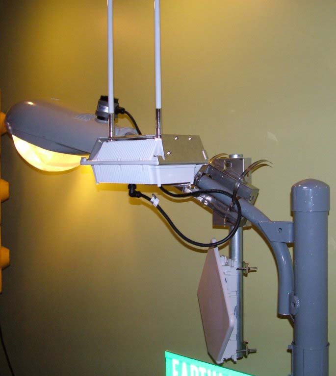
3 The following pictures are provided as examples because they are typical of EarthLink s radio installations. However, these do not represent the complete range of mounting options or equipment combinations that may be required to support a specific situation. Additionally, new product enhancements may include a modified look or system specifications. Communications Equipment Images, Diagrams and Specifications for the Tropos 5210 Outdoor MetroMesh Router Tropos 5210 Wi-Fi Node with Attached Motorola Canopy Subscriber Module

4 Tropos 5320 Wi-Fi Node

5 Tropos 5210 Wi-Fi Cell Exploded View
6 Images, Diagrams and Specifications for the Motorola Canopy Advantage 5.7 GHz Subscriber Module Images, Diagrams and Specifications for the Motorola Canopy Advantage 5.2 GHz Subscriber Module

7 Images, Diagrams and Specifications for the Motorola Canopy 900 MHz Subscriber Module with Connectorized Antenna Configuration Pole Top Installation Process PART 1 Install the Tropos 5210 Wi-Fi cell NOTE: Complete all documentation required per Checklist and/or Work Order 1. As provided for in the Agreement to which this Exhibit is attached, including the provisions about permitting for installations on Mounting Assets, select a Mounting Asset and a mounting location on the Mounting Asset. You can attach the Tropos 5210 cell to a street light as approved by the City for the applicable Mounting Asset. Correctly, install mount plate to pole with supplied clamps. (Diameters less than 8 use inside slots, 8 > use outside slots.) 2. Slip the flat portion of the hose clamp under the inside lip of the pole bracket. 3. Use the hose clamps to attach the pole bracket to the streetlight. Depending upon the diameter of the pole, you may need to use 2 small clamps, 2 large clamps, or 2 pairs of large clamps joined together.

8 4. Attach the sun shield of the cell to the structure with three 5/16-inch machine screws. Insert one screw through the hole in the center back of the sun shield and the other two screws through the curved slot tracks. 5. Level the sun shield by rotating the unit along the curved slot tracks. 2 built-in levels are located on the shield. Level both directions, and then tighten all screws and clamps. 6. Apply two drops of Loctite Threadlocker 242 to the base of the antenna connector thread, mount the antennas to Tropos 5210 per included instructions, and weatherproof with approved outdoor tape. 7. Slide the Tropos 5210 cell into place and secure it at the end with two #10-32 hex head machine screws. NOTE If this is to be a Gateway unit, see additional instructions in Part 2 to install data cable and access cover before mounting Follow steps for Connecting City Pole Power. Proper Use of Hose Clamps - Large Poles (>= 8 Inches)
 Metal Pole")
9 Proper Use of Hose Clamps - Small Poles (< 8 Inches) Metal Pole Mounting

10 Wood Pole Mounting Street Light Arm Mounting
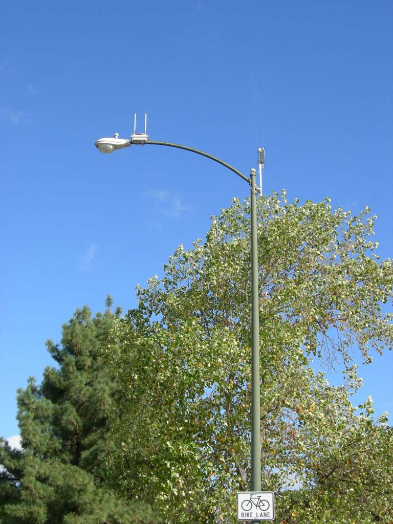
11 Example Tropos 5210 Mounting Location - Antennas Facing Upward Connect device to a streetlight power source: 1. Cover photocell to verify light works prior removing, also note North Arrow direction. 2. Remove photocell and verify that the service voltage is VAC 50/60 Hz 3. Connect the photosensor to the top of the NEMA 3 prong plug adaptor. 4. Connect the NEMA 3 prong plug from the Tropos 5210 to the photosensor connector on the streetlight. 5. Check orientation of photosensor s North Arrow and realign if needed. 6. Connect the AC plug to the Tropos 5210 and tighten hand-tight. 7. Confirm that power to the Tropos 5210 comes on observe power LED. 8. Weather proof all connection points, and Secure cables with approved cable ties. 9. RE-Verify streetlight operation by covering the photocell. 10. Complete all documentation to include GPS coordinates, Pole Location information, Street and Cross-Street, installation checklists, radio documentation and any electronic data collection that may be required.

12 Connecting Streetlight Power Install the Canopy SM Mounting arm 1. Orientate the mounting arm onto the desired side of the Tropos 5210 Sun Shield, and mount with the three long screws into the corresponding holes. 2. Attach the Canopy SM module to the end of the Mounting Arm with appropriate clamps.
13 Installing the Canopy SM Mounting arm 3. Verify that the power cable is disconnected on the designated Tropos unit. 4. Remove the connector access cover from the bottom of both the Tropos 5210, and from the Canopy SM.

14 Connecting Cat 5 Ethernet Cable from Canopy to Tropos Node 5. Run raw-unterminated, shielded Category 5 Ethernet cable appropriate for outdoor use through the Tropos 5210 access cover bulkhead openings, allowing sufficient length to terminate the cables without causing crowding in the connection area. 6. Install (Terminate) cable with a shielded RJ-45 connector, paying careful attention to follow the wiring diagram and connect to the Powered LAN port inside the Tropos 5210.
15 Inside Tropos radio, connect CAT 5 to LAN port 7. Properly secure the Access Cover, mount the Tropos 5210 into the sun shield. 8. Connect the other end of the Category 5 cable to the Canopy SM unit 9. Reconnect the Tropos Power and confirm that power to the Tropos 5210 and the Canopy SM unit comes on.
16 10. Align the Canopy SM to AP tower per instructions on work order. 11. Make Tropos 5210 and Canopy SM ready for use and secure all covers and cable connections. 12. Water proof all cable connection points with approved weatherproofing tape, and secure all cables with approved cable ties. 13. Re-Verify proper street light operation by covering the photocell. 14. Measure the radio height, take two pictures and clean up any trash around installation site. Inspection List

17 Alvarion VL System Description

18 Alvarion VL System Specifications

19 Alvarion VL SU Powered from Tropos PoE Connection

20 Installation of the Tropos Interface Cable

21 Alvarion SU Pole Top Mounting Bracket
22 Alvarion subscriber: Wind Load lbs of 100 mph. 12" x 12" antenna Weight of unit is 2.3 kg or 5.04 lbs. with the antenna. Light arm mount: Weight with 24.5 inch 1.75 OD thin wall galvanized mast = 4 lbs. 13 oz. Preliminary Wind Survivability = 165 mph Wind mph: <300 Newtons or <67.44 lbs force MIL-STD-810F Salt Fog rust resistance compliant Dimensions: 8 in x in x 3 in Rotation: 45 deg. from vertical or horizontal axis
23 Electrical Specifications FREQ. RANGE: GHz GAIN: 21dBi min. VSWR: 1.5:1 AZ. B.W (3dB): EL. B.W (3dB): POLARIZATION: Linear Vertical MAX INPUT POWER: 10W INPUT IMPEDANCE: 50 Ohms CROSS POLARIZATION: 24dB F/B RATIO: 35dB Mechanical Specifications Mechanical & Environmental Specifications DIMENSION (HxWxD): 306x306x20 mm WEIGHT: 1.0Kg. CONNECTOR: 900 MCX(M) with 15 cm coaxial cable DR- 316 RADOME: Polypropylene, UV Protected Environmental Specifications Subscriber Unit Antenna Specifications TEMP. RANGE Operating: -450 C to C VIBRATION: According to IEC SHOCK: 28g during 11ms x 3 times WIND LOAD EN: , Table A.1, Table A.2 (Heavy duty). WIND SPEED: (Survival) 200Km/Hr HUMIDITY ETS: EN : (Annex A.1.1) WATER IMMERSION: IP-67 SALT FOG: MIL-STD-810E.Method for 200 hours, IEC ICE LOADING: 25mm SOLAR RADIATION: ETS SERVICE LIFE: > 20 years LIGHTNING PROTECTION: DC GROUNDED According to IEC

24 Compliance Notifications

25 Alvarion VL Outdoor LED s
26 Installation Photographs
27 Installation Photographs
TRAPEZE NETWORKS EXTERNAL ANTENNA OPTIONS
 TRAPEZE NETWORKS EXTERNAL ANTENNA OPTIONS 2.4 GHz BAND INDOOR / OUTDOOR 60 0 Sector 120 0 Sector 180 0 Sector 360 0 Omni ANT-1060 ANT-1120 ANT-1180 ANT-1060R ANT-1120R ANT-1180R 5 GHz BAND INDOOR / OUTDOOR
Outdoor 33.6W Dual Port Passive Power-over-Ethernet Midspan For External Security Cameras and Wireless Access Points
 Outdoor 33.6W Dual Port Passive Power-over-Ethernet Midspan For External Security Cameras and Wireless Access Points Features SELV Compliant No Detection Passive Injector Gigabit Compatible Full Protection
33.6W Power over Ethernet Waterproof Adapter PoE Plus Single Port Injector for Outdoor Application
 33.6W Power over Ethernet Waterproof Adapter PoE Plus Single Port Injector for Outdoor Application Features Compliant with the IEEE802.3at Standard -40 to +60 C Temperature Range Diagnostic LEDs Full Protection
PRO 5000 CPE 1D Quick Installation Guide
 PRO 5000 CPE 1D Quick Installation Guide Introduction This Quick Installation Guide covers the basic installation of the PRO 5000 CPE. For more information, refer to the relevant sections in the Product
Datasheet. airmax 2x2 PtP Bridge Dish Antenna. Models: RD-2G24, RD-3G26, RD-5G30, RD-5G30-LW, RD-5G34. Powerful Performance for Long-Range Links
 airmax 2x2 PtP Bridge Dish Antenna Models: RD-2G24, RD-3G26, RD-5G30, RD-5G30-LW, RD-5G34 Powerful Performance for Long-Range Links Robust Design and Construction for Outdoor Use Seamless Integration with
Cisco Integrated 4G Low-profile Outdoor Saucer Antenna (ANT-4G-SR-OUT-TNC)
") CHAPTER 10 Cisco Integrated 4G Low-profile Outdoor Saucer Antenna (ANT-4G-SR-OUT-TNC) This document describes the Cisco Integrated 4G Low-profile Outdoor Saucer Antenna that is supported on the Cisco CGR
CHAPTER 10 Cisco Integrated 4G Low-profile Outdoor Saucer Antenna (ANT-4G-SR-OUT-TNC) This document describes the Cisco Integrated 4G Low-profile Outdoor Saucer Antenna that is supported on the Cisco CGR
airmax Wireless Broadband CPE Datasheet Models: AG-HP-2G16, AG-HP-2G20, AG-HP-5G23, AG-HP-5G27 High Performance, Long Range Integrated InnerFeed CPE
 airmax Wireless Broadband CPE Models: AG-HP-2G16, AG-HP-2G20, AG-HP-5G23, AG-HP-5G27 High Performance, Long Range Integrated InnerFeed CPE Easy Assembly and Installation Utilizing InnerFeed technology,
Advanced RF Isolation Variable Beamwidth Antenna. Datasheet. Model: AM-V5G-Ti. Carrier-Class 2x2 MIMO PtMP BaseStation
 Advanced RF Isolation Variable Beamwidth Antenna Model: AM-V5G-Ti Carrier-Class 2x2 MIMO PtMP BaseStation Adjustable Beamwidth Configuration Reduced Co-Location Interference Advanced Carrier-Class PtMP
LINK GPS MGMT DATA. 5 GHz Carrier Backhaul Radio DATA MGMT GPS. Model: AF-5X LINK
 LINK GPS MGMT DATA DATA MGMT GPS LINK 5 GHz Carrier Backhaul Radio Model: AF-5X 5 GHz Carrier Backhaul Radio Model: AF-5X LINK GPS MGMT DATA DATA MGMT GPS LINK Introduction Thank you for purchasing the
NAVICOM DYNAMICS RTK BASE STATION INSTALLATION AND COMMISSIONING INSTRUCTIONS
 NAVICOM DYNAMICS RTK BASE STATION INSTALLATION AND COMMISSIONING INSTRUCTIONS 1. Locate a suitable position inside the building to install the Base Station enclosure where mains power (240V AC) is available
Canopy Surge. User Manual
 Canopy Surge Suppressor User Manual SS00-UM-en Issue 2 May 2003 2003 Motorola, Inc. All rights reserved. Printed in the U.S.A Notices Safety Precautions: Before beginning your installation, please read
CANOPY TM AP C A N O P Y C A N O P Y. Getting Started with Motorola REV 12/18/01. Specifications
 Specifications Operating Frequency Range U-NII Mid band 5.25 to 5.35 GHz Access Method TDD/TDMA Data Rate 10 Mbps Modulation Type High Index BFSK/4FSK (Optimized for interference rejection) Carrier to
Silicon Pyranometer Smart Sensor (Part # S-LIB-M003)
") (Part # S-LIB-M003) The smart sensor is designed to work with the HOBO Weather Station logger. The smart sensor has a plug-in modular connector that allows it to be added easily to a HOBO Weather Station.
(Part # S-LIB-M003) The smart sensor is designed to work with the HOBO Weather Station logger. The smart sensor has a plug-in modular connector that allows it to be added easily to a HOBO Weather Station.
Datasheet. High-Performance airmax Bridge. Models: NBE M5-19, NBE-M5-16. Uniform Beamwidth Maximizes Noise Immunity. Innovative Mechanical Design
 High-Performance airmax Bridge Models: NBE M5-19, NBE-M5-16 Uniform Beamwidth Maximizes Noise Immunity Innovative Mechanical Design High-Speed Processor for Superior Performance Overview Application Examples
Avaya WLAN 9100 External Antennas for use with the WAO-9122 Access Point
 Avaya WLAN 9100 External Antennas for use with the WAO-9122 Access Point Overview To optimize the overall performance of a WLAN in an outdoor deployment it is important to understand how to maximize coverage
HMI display Installation Guide
 HMI display Installation Guide Product Description Specifications Important Information o Package Contents o Related Documents o Accessories Cautions and Warnings Mounting and Dimensions o BAC-DIS-ENC
Arecont Vision H.264 Color or Day/Night SurroundVideo Series Installation Manual
 0 P a g e H.264 Color or Day/Night SurroundVideo Installation Manual Inside the box: A. Arecont Vision SurroundVideo camera B. Mounting template C. RJ45 female to female coupler D. Hex key E. Security
NEI-30 VEI-30 Dinion Infrared Imager NEI VEI Series. Quick Install Guide
 NEI-30 VEI-30 Dinion Infrared Imager NEI VEI Series en Quick Install Guide NEI-30 VEI-30 Dinion Infrared Imager Table of Contents en 3 Table of Contents 1 Planning 4 1.1 Hardware Requirements 4 1.2 Pre-installation
Cisco Aironet 2.4-GHz MIMO Wall-Mounted Omnidirectional Antenna (AIR-ANT2440NV-R)
") Cisco Aironet 2.4-GHz MIMO Wall-Mounted Omnidirectional Antenna (AIR-ANT2440NV-R) This document outlines the specifications for the Cisco Aironet 2.4-GHz MIMO Wall-Mounted Omnidirectional Antenna (AIR-ANT2440NV-R)
Cisco Aironet 2.4-GHz MIMO Wall-Mounted Omnidirectional Antenna (AIR-ANT2440NV-R) This document outlines the specifications for the Cisco Aironet 2.4-GHz MIMO Wall-Mounted Omnidirectional Antenna (AIR-ANT2440NV-R)
Datasheet. High-Performance airmax Bridge. Models: NBE-M2-13, NBE-M5-16, NBE M5-19. Uniform Beamwidth Maximizes Noise Immunity
 High-Performance airmax Bridge Models: NBE-M2-13, NBE-M5-16, NBE M5-19 Uniform Beamwidth Maximizes Noise Immunity Innovative Mechanical Design High-Speed Processor for Superior Performance Overview Application
Home Signal Distribution Kit for Satellite TV Plus SIRIUS
 SR-101C SIRIUS/DBS Signal Combiner System SR-2261 Combiner-Outdoor Made in China DBS IN SIRIUS IN SR-101C SIRIUS/DBS Signal Combiner System SR-2251 Splitter-Indoor Made in China DC IN DBS OUT SIRIUS OUT
Wind Direction Smart Sensor (S-WDA-M003)
") (S-WDA-M003) The Wind Direction smart sensor is designed to work with HOBO Stations. The smart sensor has a plug-in modular connector that allows it to be added easily to a HOBO Station. All sensor parameters
(S-WDA-M003) The Wind Direction smart sensor is designed to work with HOBO Stations. The smart sensor has a plug-in modular connector that allows it to be added easily to a HOBO Station. All sensor parameters
Waveguide Access Point WGA631. Product Guide
 Waveguide Access Point Product Guide Waveguide Access Point Contents 1. Description............................ 3 2. Application............................ 3 3. Technical data... 4 4. Physical interfaces......................
UHF DIPOLE ANTENNA AS-2810C/SRC
 TECHNICAL MANUAL OPERATION AND INSTALLATION INSTRUCTIONS UHF DIPOLE ANTENNA AS-2810C/SRC Valcom Limited 175 Southgate Drive, P.O.Box 603, Guelph, Ontario, Canada N1H 6L3 Tel: 519-824-3220 Fax: 519-824-3411
High-Performance airmax Bridge. Datasheet. Models: NBE M5-19, NBE-M5-16, NBE-M2-400, NBE-M5-400, NBE-M5-300. Uniform Beamwidth Improves Noise Immunity
 High-Performance airmax Bridge Models: NBE M5-19, NBE-M5-16, NBE-M2-400, NBE-M5-400, NBE-M5-300 Uniform Beamwidth Improves Noise Immunity More Efficient Footprint Faster Processor Increases Performance
Stand Alone POTS Fiber Optic System. P31372 Station (Subscriber) Unit P31379 Remote (Exchanger) Unit. Description & Installation
 Unit P31379 Remote (Exchanger) Unit. Description & Installation") Stand Alone POTS Fiber Optic System P31372 Station (Subscriber) Unit P31379 Remote (Exchanger) Unit Description & Installation Printed in USA 09/11 TO466 Rev. A Table of Contents Page 1.0 SCOPE 2 2.0 PRODUCT
Stand Alone POTS Fiber Optic System P31372 Station (Subscriber) Unit P31379 Remote (Exchanger) Unit Description & Installation Printed in USA 09/11 TO466 Rev. A Table of Contents Page 1.0 SCOPE 2 2.0 PRODUCT
Datasheet. High-Performance airmax Bridge. Models: PBE-M5-620, PBE-M5-400, PBE-M5-300, PBE-M2-400. Uniform Beamwidth Maximizes Noise Immunity
 Datasheet High-Performance airmax Bridge Models: PBE-M5-620, PBE-M5-400, PBE-M5-300, PBE-M2-400 Uniform Beamwidth Maximizes Noise Immunity Innovative Mechanical Design High-Speed Processor for Superior
TerraWave Solutions MIMO Site Survey Battery Pack (Part # TW-SSBP-007) Instructions For Use
 Instructions For Use") Standard Shipping Contents of the TW-SSBP-007: 1 qty Site Survey Battery Pack (Diagram 1) 1 qty Charger (Diagram 2) 1 qty RJ-45 Red (802.3af) POE Cable (Diagram 3) 1 qty 2 56 Volt Power Cord (Diagram 4)
Standard Shipping Contents of the TW-SSBP-007: 1 qty Site Survey Battery Pack (Diagram 1) 1 qty Charger (Diagram 2) 1 qty RJ-45 Red (802.3af) POE Cable (Diagram 3) 1 qty 2 56 Volt Power Cord (Diagram 4)
Laserlyte-Flex Alignment System
 Laserlyte-Flex Alignment System LaserLyte-Flex The LaserLyte-Flex Alignment System is a unique, interchangeable, low cost plug and play laser system. Designed specifically for aligning and positioning
M2 Antenna Systems, Inc. Model No: KT34M2
 M2 Antenna Systems, Inc. Model No: KT34M2 10m f, MHz G, dbi F/B, db 28.0 7.3 18 28.2 7.3 23 28.4 7.4 25 28.6 7.5 24 29.2 7.6 20 15m f, MHz G, dbi F/B, db 21.0 6.9 19 21.1 6.9 22 21.2 7.0 24 21.3 7.0 24
Home Signal Distribution Kit for Cable TV Plus SIRIUS
 Home Signal Distribution Kit for Cable TV Plus SIRIUS For Use With a Single SIRIUS Radio Installation Manual Thank you for purchasing the Home Signal Distribution Kit for Cable TV Plus SIRIUS The Home
ANOISON HPQN SERIES HPQN CONNECTORS INTERFACE DIMENSIONS. Description. Interface Dimensions 21 Characteristics
 SERIES HPQN CONNECTORS DESCRIPTION CONTENT Designed by James Qu at Anoison in 2006, the HPQN is a quick locking version of the widely used type N connector. By replacing the threaded interface of the original
Ten Port Multi-Band Antenna
 DATA SHEET Eight High Broadband ports simultaneously covering PCS, AWS / AWS-3 and WCS bands Eight High Broadband ports with two Low Band ports in one antenna Excellent elevation side-lobe performance
AV106 BASESTATION ANTENNA SERIES
 GSM 1800, DECT : AV106 SERIES AV106 BASESTATION ANTENNA SERIES AV106 AV109 and AV112 series contain excellent basestation antenna solutions for GSM 1800 and DECT networks. The -3 db beamwidths are 60º,
Installation & Weatherproofing Guide for ENCOM Broadband Radios
 Installation & Weatherproofing Guide for ENCOM Broadband Radios Read the following instructions before proceeding with your ENCOM Wireless Radio installation. Keep these instructions in safe location for
Quick Installation Guide 24-port PoE switch with 2 copper Gigabit ports and 2 Gigabit SFP ports (af Version 15.4W)
") Quick Installation Guide 24-port PoE switch with 2 copper Gigabit ports and 2 Gigabit SFP ports (af Version 15.4W) Table of Contents Introduction.. Power Over Ethernet (PoE) & Features.... Unpacking and
Quick Installation Guide 24-port PoE switch with 2 copper Gigabit ports and 2 Gigabit SFP ports (af Version 15.4W) Table of Contents Introduction.. Power Over Ethernet (PoE) & Features.... Unpacking and
ScreenLogic Wireless Connection Kit. Installation Guide. pool/spa control system
 pool/spa control system ScreenLogic Wireless Connection Kit Installation Guide P/N 520663 - Rev B 8 Technical Support Contact Technical Support at: Sanford, North Carolina (8 A.M. to 5 P.M.) Phone: (800)
Broadband Telecommunications Drop Amplifier
 INSTALL SHEET BDA Broadband Telecommunications Drop Amplifier Introduction The Broadband Telecommunications Drop Amplifier (BDA) is a two-way, 1 GHz amplifier designed for customer-premise amplification
INSTALLATION AND OPERATING INSTRUCTIONS For Model GL1 Gate Locks
 Securitron Magnalock Corp. www.securitron.com ASSA ABLOY, the global leader Tel 800.624.5625 techsupport@securitron.com in door opening solutions INSTALLATION AND OPERATING INSTRUCTIONS For Model GL1 Gate
ProCurve External Access Point Antennas
 Certified for use with ProCurve Wireless Access Point 420, the ProCurve family of access point antennas is specifically designed to meet the needs of today's most demanding wireless LAN deployments. ProCurve
Cellular Wireless Antennas
 Cellular Wireless Antennas A Technical Brief GarrettCom Inc., November 2010 Overview The Cellular Wireless Antenna Technical brief is provided to assist with the design and deployment of the DX940 Cellular
FullAXS CONNECTOR SEALING & CABLE ASSEMBLY
 FullAXS CONNECTOR SEALING & CABLE ASSEMBLY System Solution Guide Next Generation x-tta Solution Next generation WiMAX and Long Term Evolution (LTE) Fiber/Power/Signal To The Antenna (x-tta) connectivity
Datasheet. High-Performance airmax Bridge. Models: PBE-5AC-300, PBE-5AC-400, PBE-5AC-500, PBE-5AC-620. Uniform Beamwidth Maximizes Noise Immunity
 Datasheet High-Performance airmax Bridge Models: PBE-5AC-300, PBE-5AC-400, PBE-5AC-500, PBE-5AC-620 Uniform Beamwidth Maximizes Noise Immunity Innovative Mechanical Design High-Speed Processor for Superior
ETC TWO STAGE ELECTRONIC TEMPERATURE CONTROL
 RANCO INSTALLATION INSTRUCTIONS ETC TWO STAGE ELECTRONIC TEMPERATURE CONTROL Relay Electrical Ratings PRODUCT DESCRIPTION The Ranco ETC is a microprocessor-based family of electronic temperature controls,
LevelOne IFE-0500 4-Port PoE + 1-Port TP Industrial Fast Ethernet Switch User Manual
 LevelOne IFE-0500 4-Port PoE + 1-Port TP Industrial Fast Ethernet Switch User Manual Ver. 1.0.0-0711 1 FCC Warning This Equipment has been tested and found to comply with the limits for a Class-A digital
Hinke Antennas October 2010
 Hinke Antennas October 2010 2 Outdoor Hinke DVB-T antenna Outdoor antenna DVB-T antenna for terrestrial digital TV Terra Linear is a brand new antenna series from Hinke, that has been developed and optimized
CelluLine CGW-TS GSM Cellular Gateway. Installation and Programming Manual
 CelluLine CGW-TS GSM Cellular Gateway Installation and Programming Manual CelluLine CGW-TS GSM Cellular Gateway Installation and Programming Manual CGWTS-M001A Version 1, Release 1, December 2004 NOTICE
About the HotWire 7900 10-Slot Standalone Shelf
 TM HotWire Model 7900 10-Slot Standalone Shelf Installation Instructions Document Number 7900-A2-GN10-10 About the HotWire 7900 10-Slot Standalone Shelf The HotWire 7900 10-Slot Standalone Shelf is designed
Clear Glass Sensor. Ordering Information E3S-CR67/62. Optimum Sensor for Detecting Transparent Glass and Plastic Bottles
 Clear Glass Sensor Optimum Sensor for Detecting Transparent Glass and Plastic Bottles E3S-CR67/62 Retroreflective Sensor smoothly detects 5-mm gaps. Detects transparent bottles that have a lens effect.
KNX R. Rain Sensor. Installation and Adjustment
 EN KNX R Rain Sensor Installation and Adjustment 1 Content 1. Description... 3 1.1. Technical specifications... 3 2. Installation and commissioning... 4 2.1. Installation notes... 4 2.2. Location... 4
EZ-48-3AB-125-35 Weather Station Mounting Tripod and Mast
 EZ-48-3AB-125-35 Weather Station Mounting Tripod and Mast EZ-125-35M 35 Mast Extension (Optional) EZ-125-SK Stake Kit (Optional) EZ-46-3 Tar Pad Kit (Optional) EZ-GWA Guy Wire Kit (Optional) Ambient Weather
ANTENNER och TILLBEHÖR
 ANTENNER och TILLBEHÖR Antenner Fästen Monteringstillbehör Kablar Kontakter SPARK / DB / 6 ANTENNA TYPE VHF fiberglass antenna incl. 5 mtr RG-58 and 1 pc PL-259 connector FREQUENCY 156-162 MHz IMPEDANCE
EH-20 20m antenna. By VE3RGW
 EH-20 20m antenna By VE3RGW Equivalent circuit of EH-20 (prototype 2A) antenna system. Upper cylinder Lower cylinder Ground Counter pose Phasing coil Impedance transformer and tune circuit Tune coil Feed
Datasheet. High-Performance airmax ac Bridge. Models: NBE-5AC-16, NBE 5AC-19. Uniform Beamwidth Maximizes Noise Immunity. Innovative Mechanical Design
 High-Performance airmax ac Bridge Models: NBE-5AC-16, NBE 5AC-19 Uniform Beamwidth Maximizes Noise Immunity Innovative Mechanical Design High-Speed Processor for Superior Performance Overview Application
Product Specification instalert Rapid Messenger Variable Message Sign
 instalert 2 units to cover any application instalert 18 (ia18): 18 x 28 full matrix instalert 24: (ia24): 24 x 60 full matrix Size, Weight without battery ia18: 30 x 20 x 2.74, 29 lbs ia24: Folds to fits
Datasheet. 5 GHz, airmax Technology Solutions. Models: LBE-M5-23, LBE-5AC-23, LBE-5AC-16-120. Lightweight, Low-Cost Solution
 5 GHz, airmax Technology Solutions Models: LBE-M5-23, LBE-5AC-23, LBE-5AC-16-120 Lightweight, Low-Cost Solution Full Adjustment Flexibility Quick Assembly and Installation Application Examples The LiteBeam
ADSL Modem Installation Guide. Model # 36R515 Part # 030-300108 Rev. D Revision Date 12/2000. ADSL Modem Installation Guide
 ADSL Modem Installation Guide Model # 36R515 Part # 030-300108 Rev. D Revision Date 12/2000 ADSL Modem Installation Guide Installation Instructions Westell ADSL Modem 1. Package Inspection and Contents...2
LIEBERT VNSA Installation Sheet
 LIEBERT VNSA Installation Sheet Description The Liebert vnsa network switch is designed for connecting multiple Ethernet-ready devices and comes in various models. The unit may have: A Liebert icom display
Next-Gen 2x2 Dual Polarity MIMO Omni Antenna. Datasheet. Models: AMO-2G10, AMO-2G13, AMO-3G12, AMO-5G10, AMO-5G13. High Performance, Long Range
 Next-Gen 2x2 Dual Polarity MIMO Omni Antenna Models: AMO-2G10, AMO-2G13, AMO-3G12, AMO-5G10, AMO-5G13 High Performance, Long Range Seamlessly Integrates with RocketM 360 Coverage Overview Omnidirectional
SMA Waterproof. Cable Assembly. Filtered Audio Connector. Dataport Receptacle. Dataport Plug
 INTERCONNECT SOLUTIONS FOR RUGGEDIZED COMMUNICATIONS GPS Antenna Gooseneck Adapter TNC Waterproof Cable Assembly Communication radios often carry critical public safety information and must operate reliably
(US J9380A/B, WW J9383A/B).
.") VIEW Certified The MSM310-R is a Wi-Fi Alliance authorized Wi-Fi CERTIFIED 802.11a/b/g product. The Wi-Fi CERTIFIED Logo is a certification mark of the Wi-Fi Alliance. The MSM310-R is certified under the
VIEW Certified The MSM310-R is a Wi-Fi Alliance authorized Wi-Fi CERTIFIED 802.11a/b/g product. The Wi-Fi CERTIFIED Logo is a certification mark of the Wi-Fi Alliance. The MSM310-R is certified under the
Overview. Sector Coverage. Datasheet. Utilize airmax Technology* PtMP (Point to Multi-Point) Link Example
 Link Example") 2x2 MIMO BaseStation Sector Antenna Models: AM-9M13, AM-2G15-120, AM-2G16-90, AM-3G18-120, AM-5G16-120, AM-5G17-90, AM-5G19-120, AM-5G20-90 High Performance, Long Range Seamlessly Integrates with RocketM
2x2 MIMO BaseStation Sector Antenna Models: AM-9M13, AM-2G15-120, AM-2G16-90, AM-3G18-120, AM-5G16-120, AM-5G17-90, AM-5G19-120, AM-5G20-90 High Performance, Long Range Seamlessly Integrates with RocketM
Telephone- and leased line modem for industrial applications TD-36
 Telephone- and leased line modem for industrial applications TD-36 Modem for industrial PSTN- and leased line applications The TD-36 is an analogue V.34 PSTN modem as well as an industrial 2-wire leased
ST Series POWER SUPPLIES USER INSTRUCTIONS
 Introduction These instructions detail the installation and operation requirements for the ST20 & ST35 power supplies. These have been designed for operation in RV s providing a DC power system, with optional
Times Microwave Systems Hermetically Sealed Assemblies
 SCOPE This Specification details the Electrical, Mechanical and Environmental Characteristics of Times Microwave Systems MILTECH 340.34 Diameter Hermetically Sealed Coaxial Transmission Lines. This product
No Phone Line II-48 System
 Used in conjunction with an EntraGuard Telephone Entry System, the -48 provides No Phone Line communication and door or gate control through existing building telephone lines without the need to purchase
2013 Wireless Video Intercom INSTALLATION GUIDE
 2013 Wireless Video Intercom INSTALLATION GUIDE INDEX System configuration and wiring VL-SWD501 System Component.. 4 VL-SWD501EX wiring schematic diagram VL-SWD501EX wiring type and length... 5.... 6 Door
SCREENLOGIC INTERFACE WIRELESS CONNECTION KIT
 SCREENLOGIC INTERFACE WIRELESS CONNECTION KIT FOR INTELLITOUCH AND EASYTOUCH CONTROL SYSTEMS INSTALLATION GUIDE IMPORTANT SAFETY INSTRUCTIONS READ AND FOLLOW ALL INSTRUCTIONS SAVE THESE INSTRUCTIONS Technical
4.3-inch Back-Up Camera
 TM 4.-inch Back-Up Camera Model No.: PKC0BU4 Owner s Manual and Warranty Information Read these instructions completely before using this product. Retain this Owner s Manual for future reference. INTRODUCTION
Instruction Sheet ACS-101. General Description. Specifications. Amplified Broadband UHF Combiner-Splitter. Overall. Antenna Splitter.
 ACS-101 Amplified Broadband UHF Combiner-Splitter General Description The ACS-101 (Antenna Combiner Splitter 10 to 1) is an amplified and filtered broadband splitter-combiner. It allows up to 10 base stations
MCR1900 Media Converter 19-Slot Chassis
 MCR1900 Media Converter 19-Slot Chassis Installation Guide Part #5500304-11 Copyright Statement This document must not be reproduced in any way whatsoever, either printed or electronically, without the
Installing the Broadband Global Area Network (BGAN) Fixed Mount Kit
 Fixed Mount Kit") Installing the Broadband Global Area Network (BGAN) Fixed Mount Kit Product description BGAN fixed mount kit Although the BGAN satellite modem terminal is designed for portable use, the BGAN Fixed Mount
Installing the Broadband Global Area Network (BGAN) Fixed Mount Kit Product description BGAN fixed mount kit Although the BGAN satellite modem terminal is designed for portable use, the BGAN Fixed Mount
AXIS T81B22 DC 30W Midspan
 INSTALLATION GUIDE AXIS T81B22 DC 30W Midspan ENGLISH About this Document This document includes instructions for installing AXIS T81B22 on your network. Previous experience of networking will be beneficial
Express5800/120Ed. Rack Mount Kit Installation Procedures PN: 455-01607-001
 Express5800/120Ed Rack Mount Kit Installation Procedures PN: 455-01607-001 Proprietary Notice and Liability Disclaimer The information disclosed in this document, including all designs and related materials,
Radiant Temperature Sensor TY7321
 AB-5361-U Specifications/Instructions Radiant Temperature TY7321 General TY7321 Radiant Temperature s are designed to measure infrared radiation from perimeter windows and walls and provide a proportional
OPERATING INSTRUCTIONS
 24 HOUR IMMERSION HEATER TIME CONTROLLER Cat. No TS900B OPERATING INSTRUCTIONS TS900B 24 Hour Immersion Heater Time Controller 24 hour programme ring Self-cancelling and Override switch Setting pins Time
Antenna Guide. Wireless LAN Antennas of the BAT family. BAT Antenna Guide BAT Release 09 05/2015
 Antenna Guide Wireless LAN Antennas of the BAT family Release 9 5/215 Technical Support https://hirschmann-support.belden.eu.com The naming of copyrighted trademarks in this manual, even when not specially
Wiser Panel Meter, Model Number WISERCTPM200 Installer s Guide
 Instruction Bulletin EAV85226 08/2014 Wiser Panel Meter, Model Number WISERCTPM200 Installer s Guide Retain for future use. Product Description Kit Contents The Wiser Panel Meter is for use in energy management
Modular I/O System Analog and Digital Interface Modules
 OPERATING INSTRUCTIONS Modular I/O System Analog and Digital Interface Modules Installation Operation Maintenance Document Information Document ID Title: Operating Instructions Modular I/O System Part
Mitel DECT Base Stations
 Mitel DECT Base Stations On-site Mobility for Professionals The Mitel BS300 range of base stations offers a variety of coverage patterns to suit different situations. By choosing the right mix of base
Full_IG.book Page 1 Monday, January 9, 2012 6:11 PM. ProSafe 24 Port Gigabit Switch Installation Guide
 Full_IG.book Page 1 Monday, January 9, 2012 6:11 PM ProSafe 24 Port Gigabit Switch Installation Guide Full_IG.book Page 2 Monday, January 9, 2012 6:11 PM 2011 NETGEAR, Inc. All rights reserved. No part
800 10766 700 MHz Dual Band 8', 65 Degree Antenna RET
 8 766 7 MHz Dual Band 8', 65 Degree Antenna RET X-polarized (+45 and -45 ). UV resistant fiberglass radomes. Wideband vector dipole technology. DC Grounded metallic parts for impulse suppression. RET motor
PCS300 Universal IP Reporting Module V1.0
 PCS300 Universal IP Reporting Module V1.0 Reference and Installation Manual Patents: One or more of the following US patents may apply: 7046142, 6215399, 6111256, 6104319, 5920259, 5886632, 5721542, 5287111,
PS6500 Storage Arrays Rack Mount Instructions
 PS6500 Storage Arrays Rack Mount Instructions Part Number: R724M Rev. A01 Copyright 2010 Dell, Inc. All rights reserved. Dell is a trademark of Dell, Inc. EqualLogic is a registered trademark. All trademarks
Cable Tie Mounting Bases
 Temperature Rating: 0ºC to 66ºC (32ºF to 150ºF) *Synthetic Rubber Adhesive Choose from adhesive-backed, epoxy or screw mounting bases! Available in a variety of materials for both indoor and outdoor use
MILLENIUM INSTALLATION MANUAL NTR 735 A. Simple Automation Control Module (MAS)
") MILLENIUM Table of contents 1. INTRODUCTION 1 2. HARDWARE DESCRIPTION 2 3. INSTALLATION 5 4. CONNECTION 6 5. USER SAFETY AND PROTECTION OF EQUIPMENT 8 1. Introduction The MILLENIUM series has been designed
MILLENIUM Table of contents 1. INTRODUCTION 1 2. HARDWARE DESCRIPTION 2 3. INSTALLATION 5 4. CONNECTION 6 5. USER SAFETY AND PROTECTION OF EQUIPMENT 8 1. Introduction The MILLENIUM series has been designed
Model 201 Wiegand Touchpad Reader Installation Guide
 Model 201 Wiegand Touchpad Reader Installation Guide P/N 460353001C 15AUG11 2011 UTC Fire & Security. All rights reserved. This document may not be copied in whole or in part or otherwise reproduced without
Machine-to-Machine Management System. Datasheet. Models: mport, mport-s, mpower, mpower Mini, mpower Pro, mfi-cs, mfi-ds, mfi-ths, mfi-msc, mfi-msw
 Machine-to-Machine Management System Models: mport, mport-s, mpower, mpower Mini, mpower Pro, mfi-cs, mfi-ds, mfi-ths, mfi-msc, mfi-msw Automated Machine Control Sensor Data Collection and Analytics Plug
FTW 175-2 Wireless Monitoring System Reference Manual Part Number 7911752
 Wireless Monitoring System Reference Manual Part Number 7911752 SERIAL NUMBER Flash Technology, 332 Nichol Mill Lane, Franklin, TN 37067 www.spx.com/en/flash-technology (615) 261-2000 Front Matter Abstract
DLB 5-20. Outdoor Wireless Device COPYRIGHT 2015 LIGOWAVE
 DLB 5-2 Outdoor Wireless Device COPYRIGHT 215 LIGOWAVE DLB 5-2 LigoWave s DLB 5-2 delivers the highest performance and stability available in the 5 GHz CPE class. This product combines a highly advanced
WARNING: FAILURE TO FOLLOW THESE RULES MAY RESULT IN SERIOUS PERSONAL INJURY CAUTION: INSTALLATION LOCATION:
 Revision Level: 01 Revision Date: 07/07/2011 Please read all instructions carefully to help ensure a correct and SAFE installation of your Second Wind Ultraviolet Germicidal Air Purifier. Failure to do
Options for ABB drives, converters and inverters. User s manual FDPI-02 diagnostics and panel interface
 Options for ABB drives, converters and inverters User s manual FDPI-02 diagnostics and panel interface Table of contents Table of contents 3 1. FDPI-02 diagnostics and panel interface Safety..............................................
Installation Guide. WSD-100 Wind Speed and Direction Sensor For XR5 Data Loggers. February, 2011
 WSD-100 Wind Speed and Direction Sensor For XR5 Data Loggers Installation Guide February, 2011 Pace Scientific Inc www.pace-sci.com Tel: 704-799-0688 sales@pace-sci.com 1 Disclaimer The following warranty
5-port / 8-port 10/100BaseTX Industrial Ethernet Switch User Manual
 5-port / 8-port 10/100BaseTX Industrial Ethernet Switch User Manual Content Overview... 1 Introduction... 1 Features... 3 Packing List... 4 Safety Precaution... 4 Hardware Description... 5 Front Panel...
2.4M SERIES 1241 ANTENNA
 4096-859 Revision A August 7, 2012 2.4M SERIES 1241 ANTENNA GENERAL DYNAMICS SATCOM Technologies 1500 Prodelin Drive Newton NC 28658USA Phone 828-464-4141 www.gdsatcom.com Prodelin Corporation Page 1 8/17/2012
Moxa EtherDevice Switch
 Moxa EtherDevice Switch EDS-205 Hardware Installation Guide Third Edition, June 2008 2008 Moxa Inc., all rights reserved. Reproduction without permission is prohibited. P/N: 1802002050000 Overview The
Indoor/Outdoor airmax CPE. Datasheet. Models: NSM2, NSM3, NSM365, NSM5, locom2, locom5, locom9. Cost-Effective, High-Performance
 Indoor/Outdoor CPE Models: NSM2, NSM3, NSM365, NSM5, locom2, locom5, locom9 Cost-Effective, High-Performance Compact and Versatile Design Powerful Integrated Antenna Overview Leading-Edge Industrial Design
ENERGY SOLUTIONS RESIDENTIAL STORAGE BATTERY SYSTEM
 ENERGY SOLUTIONS RESIDENTIAL STORAGE BATTERY SYSTEM MAKING SMART TOWNS, BUILDING SMART COMMUNITIES WHY PANASONIC? RESIDENTIAL STORAGE BATTERY SYSTEM The next evolution in solar energy solutions. Panasonic
InnoMedia ESBC 9580-4B. Quick Install Guide. www.innomedia.com 1
 InnoMedia ESBC 9580-4B Quick Install Guide www.innomedia.com 1 Table of Contents Introduction 2 Package Contents 2 CAUTION 2 Installation 3 Wall-Mounting Instructions 5 Troubleshooting 6 Appendix A. LED