THREE PHASE vs SINGLE PHASE SUPPLY
|
|
|
- Julia Booth
- 7 years ago
- Views:
Transcription
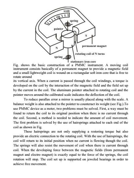
1 THREE PHASE vs SINGLE PHASE SUPPLY Presently 3-ø AC system is very popular and being used worldwide for power generation, power transmission, distribution and for electric motors. Three phase system has the following advantages as compare to single phase system: 1. Power to weight ratio of 3-ø alternator is high as compare to 1-ø alternator. Means for generation for same amount of Electric Power, the size of 3-ø alternator is small as compare to 1-ø Alternator. Hence, the overall cost of alternator is reduced for generation of same amount of power. Moreover, of due to reduction in weight, transportation and 1
2 installation alternator become convenient and less space is required to accommodate the alternator in power house. 2. For electric power transmission and distribution of same amount of power, the requirement of conductor material is less in 3-ø system as compare to 1-ø system. Hence, the 3-ø transmission and distribution system is economical as compare 1-ø system. 3. Let us consider the power produced by single phase supply and 3-phase supply at unity power factor. Wave form of power produce due 1-phase supply at unity power factor is shown in figure (C) and Wave form of power produced due to 3-phase supply is shown in figure (D) below. 2

3 From power wave forms shown in figure (C) and (D) above it is clear that in 3- phase system, the instantaneous power is always constant over the cycle results in smooth and vibration free operation of machine. Whereas in 1-ø system the instantaneous power is pulsating hence change over the cycle, which leads to vibrations in machines. Power to weight ratio of three phase induction motor is high as compare to single phase induction motor. Means for same amount of Mechanical Power, the size of three phase induction motor is small as compare to single phase induction motor. Hence, the overall cost of induction motor is reduced. Moreover, due to reduction in weight, transportation and installation of induction motor become convenient and less space is required to accommodate the Induction motor. 3-phase induction motor is self-started as the magnetic flux produced by 3- phase supply is rotating in nature with constant magnitude. Whereas 1-ø induction motor is not self-started as the magnetic flux produced by 1-ø supply is pulsating in nature. Hence, we have to make some arrangement to make the 1-ø induction motor self-started. Which further increase the cost of 1-ø induction motor. 3-phase motor is having better power factor and efficiency as compare to 1-ø motor. 3
4 Power to weight ratio of 3-phase transformer is high as compare to 1-ø transformer. Means for same amount of Electric Power, the size of 3-phase transformer is small as compare to 1-ø transformer. Hence, the overall cost of transformer is reduced. Moreover, due to reduction in weight, transportation and installation of transformer become convenient and less space is required to accommodate the transformer. If fault occurs in any winding of 3-phase transformer, the rest of two winding can be used in open delta to serve the 3-phase load which is not possible in 1-ø transformer. This ability of 3-phase transformer further increase the reliability of 3-phase transformer. A 3-phase system can be used to feed a 1-ø load, whereas vice-versa is not possible. DC rectified from 3-phase supply is having the ripple factor 4% and DC rectified from 1-ø supply is having the ripple factor 48.2 %. Mean DC rectified from 3-ø supply contains less ripples as compare to DC rectified from 1-ø supply. Hence the requirement of filter is reduced for DC rectified from 3-phase supply. Which reduce the overall cost of convector. From above it clear the 3-phase system is more economical, efficient, reliable and convenient as compare to 1-ø system. There are two types of system available in electric circuit, single phase and three phase system. In single phase circuit, there will be only one phase, i.e the current will flow through only one wire and there will be one return path called neutral line to complete the circuit. So in single phase minimum amount of power can be transported. Here the generating station and load station will also be single phase. This is an old system using from previous time. In 1882, new invention has been done on polyphase system, that more than one phase can be used for generating, transmitting and for load system. Three phase circuit is the polyphase system where three phases are send together from the generator to the load. Each phase are having a phase difference of 120, i.e 120 angle electrically. So from the total of 360, three phases are equally divided into 120 each. The power in three phase system is continuous as all the three phases are involved in generating the total power. The sinusoidal waves for 3 phase system is shown below- 4
5 The three phases can be used as single phase each. So if the load is single phase, then one phase can be taken from the three phase circuit and the neutral can be used as ground to complete the circuit. Why Three Phase is preferred Over Single Phase? There are various reasons for this question because there are numbers of advantages over single phase circuit. The three phase system can be used as three single phase line so it can act as three single phase system. The three phase generation and single phase generation is same in the generator except the arrangement of coil in the generator to get 120 phase difference. The conductor needed in three phase circuit is 75% that of conductor needed in single phase circuit. And also the instantaneous power in single phase system falls down to zero as in single phase we can see from the sinusoidal curve but in three phase system the net power from all the phases gives a continuous power to the load. Till now we can say that there are three voltage source connected together to form a three phase circuit. And actually it is inside the generator. The generator is having three voltage source s which are acting together in 120 phase difference. If we can arrange three single phase circuit with 120 phase difference, then it will become a three phase circuit. So 120 phase difference is must otherwise the circuit will not work, the three phase load will not be able to get active and it may also cause damage to the system. The size or metal quantity of three phase devices is not having much difference. Now if we consider the transformer, it will be almost same size for both single phase and three phase because transformer will make only the linkage of flux. So the three phase system will have higher efficiency compared to single phase because for the same or little difference in mass of transformer, three phase line will be out 5
6 whereas in single phase it will be only one. And losses will be minimum in three phase circuit. So overall in conclusion the three phase system will have better and higher efficiency compared to the single phase system. In three phase circuit, connections can be given in two types: 1. Star connection 2. Delta connection Star Connection In star connection, there is four wire, three wires are phase wire and fourth is neutral which is taken from the star point. Star connection is preferred for long distance power transmission because it is having the neutral point. In this we need to come to the concept of balanced and unbalanced current in power system. When equal current will flow through all the three phases, then it is called as balanced current. And when the current will not be equal in any of the phase, then it is unbalanced current. In this case, during balanced condition there will be no current flowing through the neutral line and hence there is no use of the neutral terminal. But when there will be unbalanced current flowing in the three phase circuit, neutral is having a vital role. It will take the unbalanced current through to the ground and protect the transformer. Unbalanced current affects transformer and it may also cause damage to the transformer and for this star connection is preferred for long distance transmission. The star connection is shown below- 6

7 In star connection, the line voltage is 3 times of phase voltage. Line voltage is the voltage between two phases in three phase circuit and phase voltage is the voltage between one phase to the neutral line. And the current is same for both line and phase. It is shown as expression below If a balance symmetrical load is connected across three phase voltage system in parallel, then the three currents will flow in neutral wire which quantities would be same, but they would be differ by 120 (out of phase), hence the vector sum of these three currents = 0. i.e. I R + I Y + I B = 0. Victorially The voltage between any two terminals or Voltage between Line and Neutral (Star Point) is called Phase voltage or Star voltage. And the voltage between two Lines is called Line to Line Voltage or Line Voltage 7
8 Voltage, Current and Power Values in Star Connection (Y) 1. Line Voltages and Phase Voltages in Star Connection We know that the Line Voltage between Line 1 and Line 2 (from fig 3a) is V RY = V R V Y. (Vector Difference) Thus, to find vector of V RY, increase the Vector of V Y in reverse direction as shown in the dotted form in the below fig 2. Similarly, on the both ends of vector V R and Vector V Y, make perpendicular dotted lines which look like a parallelogram as shown in fig (2). The Diagonal line which divides the parallelogram into two parts, showing the value of V RY. The angle between V Y and V R vectors is 60. Hence, if V R = V Y = V B = V PH, then V RY = 2 x V PH x Cos (60 /2) = 2 x V PH x Cos 30 = 2 x V PH x ( 3/2) Since Cos 30 = 3/2 = 3 V PH Similarly, V YB = V Y V B = 3 V PH And V BR = V B V R = 3 V PH Hence, it is proved that V RY = V YB = V BR is line voltages V L in Star Connection, Therefore, in Star Connection; V L = 3 V PH or V L = 3 E PH 8
9 It is seen from the fig 2 that; Line voltages are 120 apart from each other Line voltages are 30 leading from the corresponding phase voltages The angle Ф between line currents and respective line voltages are (30 +Ф), i.e. each line current is lagging (30 +Ф) from the corresponding line voltage. 2. Line Currents and Phase Currents in Star Connection It is seen from the fig (3a) that each line is in series with individual phase winding, therefore, the value of line current is same as in Phase windings to which the line is connected. i.e.; Current in Line 1 = I R Current in Line 2 = I Y Current in Line 3 = I B Since, the flowing currents in all three lines are same, and the individual current in each line is equal to the corresponding phase current, therefore; I R = I Y = I B = I PH. The phase current 9
10 Line Current = Phase Current I L = I PH In simple words, the value of Line Current and Phase Current is same in Star Connection. 3. Power in Star Connection In a three phase AC circuit, the total True or Active power is the sum of the three phase power. Or the sum of the all three phase powers is the Total Active or True Power. Hence, total active or true power in a three phase AC system; Total True or Active Power = 3 Phase Power Or P = 3 x V PH x I PH x CosФ.. Eq (1) Good to Know: Where Cos Φ = Power factor = the phase angle between Phase Voltage and Phase Current and not between Line current and line voltage. We know that the values of Phase Current and Phase Voltage in Star Connection; I L = I PH V PH = V L / 3.. (From V L = 3 V PH ) Putting these values in power eq. (1) P = 3 x (V L / 3) x I L x CosФ.. (V PH = V L / 3) 10
11 P = 3 x 3 x (V L / 3) x I L x CosФ. {3 = 3x 3} P = 3 x V L x I L x CosФ Hence proved; Power in Star Connection, P = 3 x V PH x I PH x CosФ or P = 3 x V L x I L x CosФ Similarly, Total Reactive Power = Q = 3 x V L x I L x SinФ Good to know: Reactive Power of Inductive coil is taken as Positive (+) and that of a Capacitor as Negative (-). Also, the total apparent power of the three phases Total Apparent Power = S = 3 x V L x I L Or, S = (P 2 + Q 2 ) Delta Connection In delta connection, there is three wires alone and no neutral terminal is taken. Normally delta connection is preferred for short distance due to the problem of unbalanced current in the circuit. The figure is shown below for delta connection. In the load station, ground can be used as neutral path if required. In this system of interconnection, the starting ends of the three phases or coils are connected to the finishing ends of the coil. Or the starting end of the first coil is connected to the finishing end of the second coil and so on (for all three coils) and it looks like a closed mesh or circuit as shown in fig In more clear words, all three coils are connected in series to form a close mesh or circuit. Three wires are taken out from three junctions and the all outgoing currents from junction assumed to be positive. 11
12 In Delta connection, the three windings interconnection looks like a short circuit, but this is not true, if the system is balanced, then the value of the algebraic sum of all voltages around the mesh is zero. When a terminal is open, then there is no chance of flowing currents with basic frequency around the closed mesh. Good to Remember: at any instant, the EMF value of one phase is equal to the resultant of the other two phases EMF values but in the opposite direction. Delta or Mesh Connection System is also called Three Phase Three Wire System (3-Phase 3 Wire) and it is the best and suitable system for AC Power Transmission. In delta connection, the line voltage is same with that of phase voltage. And the line current is 3 times of phase current. It is shown as expression below, 12
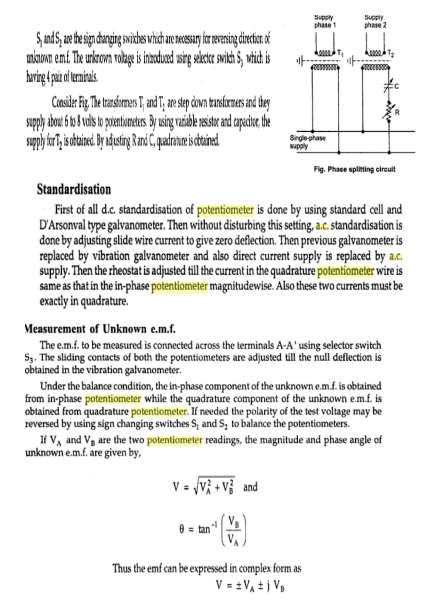
 two lines is equal to the phase voltage of the phase winding which is connected between two lines.")
13 Voltage, Current and Power Values in Delta Connection (Δ) 1. Line Voltages and Phase Voltages in Delta Connection It is seen from fig 2 that there is only one phase winding between two terminals (i.e. there is one phase winding between two wires). Therefore, in Delta Connection, the voltage between (any pair of) two lines is equal to the phase voltage of the phase winding which is connected between two lines. Since the phase sequence is R Y B, therefore, the direction of voltage from R phase towards Y phase is positive (+), and the voltage of R phase is leading by 120 from Y phase voltage. Likewise, the voltage of Y phase is leading by 120 from the phase voltage of B and its direction is positive from Y towards B. If the line voltage between; Line 1 and Line 2 = V RY Line 2 and Line 3 = V YB Line 3 and Line 1 = V BR Then, we see that V RY leads V YB by 120 and V YB leads V BR by 120. Let s suppose, V RY = V YB = V BR = V L (Line Voltage) Then V L = V PH I.e. in Delta connection, the Line Voltage is equal to the Phase Voltage. 2. Line Currents and Phase Currents in Delta Connection 13
14 It will be noted from the below (fig-2) that the total current of each Line is equal to the vector difference between two phase currents flowing through that line. i.e.; Current in Line 1= I 1 = I R I B Current in Line 2 =I 2 = I Y I R Current in Line 3 =I 3 = I B I Y {Vector Difference} The current of Line 1 can be found by determining the vector difference between I R and I B and we can do that by increasing the I B Vector in reverse, so that, I R and I B makes a parallelogram. The diagonal of that parallelogram shows the vector difference of I R and I B which is equal to Current in Line 1= I 1. Moreover, by reversing the vector of I B, it may indicate as (-I B ), therefore, the angle between I R and -I B (I B, when reversed = -I B ) is 60. If, I R = I Y = I B = I PH. The phase currents Then; The current flowing in Line 1 would be; I L or I 1 = 2 x I PH x Cos (60 /2) 14
15 = 2 x I PH x Cos 30 = 2 x I PH x ( 3/2) Since Cos 30 = 3/2 = 3 I PH i.e. In Delta Connection, The Line current is 3 times of Phase Current Similarly, we can find the reaming two Line currents as same as above. i.e., I 2 = I Y I R Vector Difference = 3 I PH I 3 = I B I Y Vector difference = 3 I PH As, all the Line current are equal in magnitude i.e. I 1 = I 2 = I 3 = I L Hence IL = 3 I PH It is seen from the fig above that; The Line Currents are 120 apart from each other Line currents are lagging by 30 from their corresponding Phase Currents The angle Ф between line currents and respective line voltages is (30 +Ф), i.e. each line current is lagging by (30 +Ф) from the corresponding line voltage. 3. Power in Delta Connection & GAIN We know that the power of each phase Power / Phase = V PH x I PH x CosФ And the total power of three phases; Total Power = P = 3 x V PH x I PH x CosФ.. (1) We know that the values of Phase Current and Phase Voltage in Delta Connection; BEAM 15
16 I PH = I L / / 3.. (From IL = 3 I PH ) V PH = V L Putting these values in power eq. (1) P = 3 x V L x ( I L / 3) x CosФ (I PH = I L / / 3) P = 3 x 3 x V L x ( I L / 3) x CosФ { 3 = 3x 3 } P = 3 x V L x I L x CosФ Hence proved; Power in Delta Connection, P = 3 x V PH x I PH x CosФ. or P = 3 x V L x I L x CosФ Good to Know: Where Cos Φ = Power factor = the phase angle between Phase Voltage and Phase Current and not between Line current and line voltage. Good to Remember: In both Star and Delta Connections, The total power on balanced load is same. I.e. total power in a Three Phase System = P = 3 x V L x I L x CosФ Good to know: Balanced System is a system where: All three phase voltages are equal in magnitude All phase voltages are in phase by each other i.e. 360 /3 = 120 All three phase Currents are equal in magnitude All phase Currents are in phase by each other i.e. 360 /3 = 120 A three phase balanced load is a system in which the load connected across three phases are identical. 16

17 In three phase circuit, star and delta connection can be arranged in four different ways- 1. Star-Star connection 2. Star-Delta connection 3. Delta-Star connection 4. Delta-Delta connection But the power is independent of the circuit arrangement of the three phase system. The net power in the circuit will be same in both star and delta connection. The power in three phase circuit can be calculated from the equation below, Since, there is three phases, so the multiple of 3 is made in the normal power equation and the PF is power factor. Power factor is a very important factor in three phase system and some times due to certain error, it is corrected by using capacitors. Comparison between Star and Delta Connections Star (Y) Connection In STAR connection, the starting or finishing ends (Similar ends) of three coils are connected together to form the neutral point. A common wire is taken out from the neutral point which is called Neutral. Delta (Δ) Connection In DELTA connection, the opposite ends of three coils are connected together. In other words, the end of each coil is connected with the start of another coil, and three wires are taken out from the coil joints There is a Neutral or Star Point Three phase four wire system is derived from Star Connections (3-Phase, 4 Wires System) We may Also derived 3 Phase 3 Wire System from Star No Neutral Point in Delta Connection Three phase three wire system is derived from Delta Connections (3-Phase, 3 Wires System) 17
18 Connection Line Current is Equal to Phase Current. i.e. Line Current = Phase Current I L = I PH Line Voltage is Equal to Phase Voltage. i.e. Line Voltage = Phase Voltage V L = V PH Line Voltage is 3 times of Phase Voltage. i.e. V L = 3 V PH The Total Power of three phases could be found by P = 3 x V L x I L x CosФ. Or P = 3 x V PH x I PH x CosФ The speeds of Star connected motors are slow as they receive 1/ 3 voltage. In Star Connection, the phase voltage is low as 1/ 3 of the line voltage, so, it needs low number of turns, hence, saving in copper. Low insulation required as phase voltage is low In Power Transmission, Star Connection system is general and typical to be used. Line Current is 3 times of Phase Current. i.e. I L = 3 I PH The Total Power of three phases could be found by P = 3 x V L x I L x CosФ or P = 3 x V PH x I PH x CosФ The speeds of Delta connected motors are high because each phase gets the total of line voltage In Delta connection, The phase voltage is equal to the line voltage, hence, it needs more number of turns. Heavy insulation required as Phase voltage = Line Voltage. In Power Distribution and industries, Delta Connection is general and typical to be used. 18

19 STAR DELTA TRANSFORMATIONS 19
20 20
21 21
22 22
23 23
24 24
25 25
26 26
27 27
28 28
29 29
30 30
31 31
32 32
33 33

34 34

35 35

36 36
37 37

38 38

39 39

40 40
41 41
42 42

43 43

44 44
45 45

46 46

47 47

48 48

49 49

50 50

51 51
52 52
53 53

54 54

55 55

56 56
57 57
58 58
59 59

60 60

61 61
62 62

63 63
64 64

65 65
66 66
67 67
68 68
69 69
70 PHASE CONTROLLED RECTIFIERS OR CONVERTERS 70

71 71
72 72
73 73
74 74
75 75
76 76

77 77
78 78
79 79
80 80
81 81
82 82
83 83
84 84

85 85
86 86
87 87
88 88
89 89
90 90
Three phase circuits
 Three phase circuits THREE PHASE CIRCUITS THREE-PHASE ADVANTAGES 1. The horsepower rating of three-phase motors and the kva rating of three-phase transformers are 150% greater than single-phase motors
The generation and supply of electricity within the U.K is achieved through the use of a 3-phase system.
 Three Phase Electricity Supplies and Systems The generation and supply of electricity within the U.K is achieved through the use of a 3-phase system. This consists of 3 separate phase conductors along
Chapter 24. Three-Phase Voltage Generation
 Chapter 24 Three-Phase Systems Three-Phase Voltage Generation Three-phase generators Three sets of windings and produce three ac voltages Windings are placed 120 apart Voltages are three identical sinusoidal
SAMPLE OF THE STUDY MATERIAL PART OF CHAPTER 3. Symmetrical Components & Faults Calculations
 SAMPLE OF THE STUDY MATERIAL PART OF CHAPTER 3 3.0 Introduction Fortescue's work proves that an unbalanced system of 'n' related phasors can be resolved into 'n' systems of balanced phasors called the
Power measurement in balanced 3 phase circuits and power factor improvement. 1 Power in Single Phase Circuits. Experiment no 1
 Experiment no 1 Power measurement in balanced 3 phase circuits and power factor improvement 1 Power in Single Phase Circuits Let v = m cos(ωt) = cos(ωt) is the voltage applied to a R-L circuit and i =
Prepared By: Sheilani Binti Shaari Department of Electrical Engineering/PKB
 Prepared By: Sheilani Binti Shaari Department of Electrical Engineering/ Course Learning Outcome (CLO) Upon completion of this course, students should be able to: Apply the principles of three phase systems,
(3 )Three Phase Alternating Voltage and Current
Three Phase Alternating Voltage and Current") EEE 2015 EECTRCS (3) Monophase 1 Three phase Three phase electric power is a common method of alternating current electric power generation, transmission, and distribution. t is a type of polyphase system
EEE 2015 EECTRCS (3) Monophase 1 Three phase Three phase electric power is a common method of alternating current electric power generation, transmission, and distribution. t is a type of polyphase system
COMPUTER AIDED ELECTRICAL DRAWING (CAED) 10EE65
 10EE65") COMPUTER AIDED ELECTRICAL DRAWING (CAED) EE Winding Diagrams: (i) DC Winding diagrams (ii) AC Winding Diagrams Terminologies used in winding diagrams: Conductor: An individual piece of wire placed in the
COMPUTER AIDED ELECTRICAL DRAWING (CAED) EE Winding Diagrams: (i) DC Winding diagrams (ii) AC Winding Diagrams Terminologies used in winding diagrams: Conductor: An individual piece of wire placed in the
DIRECT CURRENT GENERATORS
 DIRECT CURRENT GENERATORS Revision 12:50 14 Nov 05 INTRODUCTION A generator is a machine that converts mechanical energy into electrical energy by using the principle of magnetic induction. This principle
ElectroMagnetic Induction. AP Physics B
 ElectroMagnetic Induction AP Physics B What is E/M Induction? Electromagnetic Induction is the process of using magnetic fields to produce voltage, and in a complete circuit, a current. Michael Faraday
How To Understand And Understand The Theory Of Electricity
 DIRECT CURRENT AND ALTERNATING CURRENT SYSTEMS N. Rajkumar, Research Fellow, Energy Systems Group, City University Northampton Square, London EC1V 0HB, UK Keywords: Electrical energy, direct current, alternating
Coupled Inductors. Introducing Coupled Inductors
 Coupled Inductors From power distribution across large distances to radio transmissions, coupled inductors are used extensively in electrical applications. Their properties allow for increasing or decreasing
Network Theory Question Bank
 Network Theory Question Bank Unit-I JNTU SYLLABUS: Three Phase Circuits Three phase circuits: Phase sequence Star and delta connection Relation between line and phase voltages and currents in balanced
Digital Energy ITI. Instrument Transformer Basic Technical Information and Application
 g Digital Energy ITI Instrument Transformer Basic Technical Information and Application Table of Contents DEFINITIONS AND FUNCTIONS CONSTRUCTION FEATURES MAGNETIC CIRCUITS RATING AND RATIO CURRENT TRANSFORMER
Motor Fundamentals. DC Motor
 Motor Fundamentals Before we can examine the function of a drive, we must understand the basic operation of the motor. It is used to convert the electrical energy, supplied by the controller, to mechanical
EDEXCEL NATIONAL CERTIFICATE/DIPLOMA UNIT 5 - ELECTRICAL AND ELECTRONIC PRINCIPLES NQF LEVEL 3 OUTCOME 4 - ALTERNATING CURRENT
 EDEXCEL NATIONAL CERTIFICATE/DIPLOMA UNIT 5 - ELECTRICAL AND ELECTRONIC PRINCIPLES NQF LEVEL 3 OUTCOME 4 - ALTERNATING CURRENT 4 Understand single-phase alternating current (ac) theory Single phase AC
Basic Electrical Technology Dr. L. Umanand Department of Electrical Engineering Indian Institute of Science, Bangalore. Lecture - 33 3 phase System 4
 Basic Electrical Technology Dr. L. Umanand Department of Electrical Engineering Indian Institute of Science, Bangalore Lecture - 33 3 phase System 4 Hello everybody. So, in the last class we have been
Generator Stator Protection, under/over voltage, under /over frequency and unbalanced loading. Ramandeep Kaur Aujla S.NO 250447392
 1 Generator Stator Protection, under/over voltage, under /over frequency and unbalanced loading By Ramandeep Kaur Aujla S.NO 250447392 ES 586b: Theory and applications of protective relays Department of
Circuits with inductors and alternating currents. Chapter 20 #45, 46, 47, 49
 Circuits with inductors and alternating currents Chapter 20 #45, 46, 47, 49 RL circuits Ch. 20 (last section) Symbol for inductor looks like a spring. An inductor is a circuit element that has a large
Lesson 3 DIRECT AND ALTERNATING CURRENTS. Task. The skills and knowledge taught in this lesson are common to all missile repairer tasks.
 Lesson 3 DIRECT AND ALTERNATING CURRENTS Task. The skills and knowledge taught in this lesson are common to all missile repairer tasks. Objectives. When you have completed this lesson, you should be able
2. A conductor of length 2m moves at 4m/s at 30 to a uniform magnetic field of 0.1T. Which one of the following gives the e.m.f. generated?
 Extra Questions - 2 1. A straight length of wire moves through a uniform magnetic field. The e.m.f. produced across the ends of the wire will be maximum if it moves: a) along the lines of magnetic flux
Edmund Li. Where is defined as the mutual inductance between and and has the SI units of Henries (H).
.") INDUCTANCE MUTUAL INDUCTANCE If we consider two neighbouring closed loops and with bounding surfaces respectively then a current through will create a magnetic field which will link with as the flux passes
INDUCTANCE MUTUAL INDUCTANCE If we consider two neighbouring closed loops and with bounding surfaces respectively then a current through will create a magnetic field which will link with as the flux passes
NO LOAD & BLOCK ROTOR TEST ON THREE PHASE INDUCTION MOTOR
 INDEX NO. : M-142 TECHNICAL MANUAL FOR NO LOAD & BLOCK ROTOR TEST ON THREE PHASE INDUCTION MOTOR Manufactured by : PREMIER TRADING CORPORATION (An ISO 9001:2000 Certified Company) 212/1, Mansarover Civil
Principles of Adjustable Frequency Drives
 What is an Adjustable Frequency Drive? An adjustable frequency drive is a system for controlling the speed of an AC motor by controlling the frequency of the power supplied to the motor. A basic adjustable
Power Quality Paper #3
 The Effect of Voltage Dips On Induction Motors by: M D McCulloch 1. INTRODUCTION Voltage depressions caused by faults on the system affect the performance of induction motors, in terms of the production
Force on Moving Charges in a Magnetic Field
 [ Assignment View ] [ Eðlisfræði 2, vor 2007 27. Magnetic Field and Magnetic Forces Assignment is due at 2:00am on Wednesday, February 28, 2007 Credit for problems submitted late will decrease to 0% after
DHANALAKSHMI COLLEGE OF ENGINEERING DEPARTMENT OF ELECTRICAL AND ELECTRONICS ENGINEERING EE2302 - ELECTRICAL MACHINES II UNIT-I SYNCHRONOUS GENERATOR
 1 DHANALAKSHMI COLLEGE OF ENGINEERING DEPARTMENT OF ELECTRICAL AND ELECTRONICS ENGINEERING Constructional details Types of rotors EE2302 - ELECTRICAL MACHINES II UNIT-I SYNCHRONOUS GENERATOR PART A 1.
Line Reactors and AC Drives
 Line Reactors and AC Drives Rockwell Automation Mequon Wisconsin Quite often, line and load reactors are installed on AC drives without a solid understanding of why or what the positive and negative consequences
W03 Analysis of DC Circuits. Yrd. Doç. Dr. Aytaç Gören
 W03 Analysis of DC Circuits Yrd. Doç. Dr. Aytaç Gören ELK 2018 - Contents W01 Basic Concepts in Electronics W02 AC to DC Conversion W03 Analysis of DC Circuits (self and condenser) W04 Transistors and
AC Generators. Basic Generator
 AC Generators Basic Generator A basic generator consists of a magnetic field, an armature, slip rings, brushes and a resistive load. The magnetic field is usually an electromagnet. An armature is any number
Prof. Krishna Vasudevan, Prof. G. Sridhara Rao, Prof. P. Sasidhara Rao. x x. x x. Figure 10: Cross sectional view
 4 Armature Windings Main field Commutator & Brush Compole field haft v Compensating winding Armature winding Yoke Figure 10: Cross sectional view Fig. 10 gives the cross sectional view of a modern d.c.
3-Phase AC Calculations Revisited
 AN110 Dataforth Corporation Page 1 of 6 DID YOU KNOW? Nikola Tesla (1856-1943) came to the United States in 1884 from Yugosiavia. He arrived during the battle of the currents between Thomas Edison, who
Figure 1.1 Vector A and Vector F
 CHAPTER I VECTOR QUANTITIES Quantities are anything which can be measured, and stated with number. Quantities in physics are divided into two types; scalar and vector quantities. Scalar quantities have
Analog & Digital Electronics Course No: PH-218
 Analog & Digital Electronics Course No: PH-18 Lec 3: Rectifier and Clipper circuits Course nstructors: Dr. A. P. VAJPEY Department of Physics, ndian nstitute of Technology Guwahati, ndia 1 Rectifier Circuits:
Induced voltages and Inductance Faraday s Law
 Induced voltages and Inductance Faraday s Law concept #1, 4, 5, 8, 13 Problem # 1, 3, 4, 5, 6, 9, 10, 13, 15, 24, 23, 25, 31, 32a, 34, 37, 41, 43, 51, 61 Last chapter we saw that a current produces a magnetic
Chapter 12: Three Phase Circuits
 Chapter 12: Three Phase Circuits 12.1 What Is a Three Phase Circuit? 12.2 Balance Three Phase Voltages 12.3 Balance Three Phase Y to Y Connection 12.4 Other Balance Three Phase Connections 12.5 Power in
The following table shows approximate percentage wise the
 SHORT-CIRCUIT CALCULATION INTRODUCTION Designing an electrical system is easy and simple, if only the normal operation of the network is taken into consideration. However, abnormal conditions which are
Measurement of Power in single and 3-Phase Circuits. by : N.K.Bhati
 Measurement of Power in single and 3-Phase Circuits by : N.K.Bhati A specifically designed programme for Da Afghanistan Breshna Sherkat (DABS) Afghanistan 1 Areas Covered Under this Module 1. Power in
Power Systems Engineering Research Center
 Power Systems Engineering Research Center PSERC Background Paper What is Reactive Power? Peter W. Sauer Department of Electrical and Computer Engineering University of Illinois at Urbana-Champaign September
8 Speed control of Induction Machines
 8 Speed control of Induction Machines We have seen the speed torque characteristic of the machine. In the stable region of operation in the motoring mode, the curve is rather steep and goes from zero torque
45. The peak value of an alternating current in a 1500-W device is 5.4 A. What is the rms voltage across?
 PHYS Practice Problems hapters 8- hapter 8. 45. The peak value of an alternating current in a 5-W device is 5.4 A. What is the rms voltage across? The power and current can be used to find the peak voltage,
SYNCHRONOUS MACHINES
 SYNCHRONOUS MACHINES The geometry of a synchronous machine is quite similar to that of the induction machine. The stator core and windings of a three-phase synchronous machine are practically identical
1. The diagram below represents magnetic lines of force within a region of space.
 1. The diagram below represents magnetic lines of force within a region of space. 4. In which diagram below is the magnetic flux density at point P greatest? (1) (3) (2) (4) The magnetic field is strongest
Three-Phase Electric Power Distribution for Computer Data Centers
 Three-hase Electric ower Distribution for Computer Data Centers WHITE AER E901 Geist January 008 Summary This paper will describe the characteristics of three-phase power and outline the advantages of
The full wave rectifier consists of two diodes and a resister as shown in Figure
 The Full-Wave Rectifier The full wave rectifier consists of two diodes and a resister as shown in Figure The transformer has a centre-tapped secondary winding. This secondary winding has a lead attached
Chapter 22: Electric motors and electromagnetic induction
 Chapter 22: Electric motors and electromagnetic induction The motor effect movement from electricity When a current is passed through a wire placed in a magnetic field a force is produced which acts on
Three-phase AC circuits
 Three-phase AC circuits This worksheet and all related files are licensed under the Creative Commons Attribution License, version 1.0. To view a copy of this license, visit http://creativecommons.org/licenses/by/1.0/,
Lecture - 4 Diode Rectifier Circuits
 Basic Electronics (Module 1 Semiconductor Diodes) Dr. Chitralekha Mahanta Department of Electronics and Communication Engineering Indian Institute of Technology, Guwahati Lecture - 4 Diode Rectifier Circuits
PHASOR DIAGRAMS HANDS-ON RELAY SCHOOL WSU PULLMAN, WA. RON ALEXANDER - BPA
 PHASOR DIAGRAMS HANDS-ON RELAY SCHOOL WSU PULLMAN, WA. RON ALEXANDER - BPA What are phasors??? In normal practice, the phasor represents the rms maximum value of the positive half cycle of the sinusoid
Reading assignment: All students should read the Appendix about using oscilloscopes.
 10. A ircuits* Objective: To learn how to analyze current and voltage relationships in alternating current (a.c.) circuits. You will use the method of phasors, or the vector addition of rotating vectors
ELECTRIC FIELD LINES AND EQUIPOTENTIAL SURFACES
 ELECTRIC FIELD LINES AND EQUIPOTENTIAL SURFACES The purpose of this lab session is to experimentally investigate the relation between electric field lines of force and equipotential surfaces in two dimensions.
Lecture Notes ELE A6
 ecture Notes EE A6 Ramadan El-Shatshat Three Phase circuits 9/12/2006 EE A6 Three-phase Circuits 1 Three-phase Circuits 9/12/2006 EE A6 Three-phase Circuits 2 Advantages of Three-phase Circuits Smooth
Objectives. Electric Current
 Objectives Define electrical current as a rate. Describe what is measured by ammeters and voltmeters. Explain how to connect an ammeter and a voltmeter in an electrical circuit. Explain why electrons travel
5.3 The Cross Product in R 3
 53 The Cross Product in R 3 Definition 531 Let u = [u 1, u 2, u 3 ] and v = [v 1, v 2, v 3 ] Then the vector given by [u 2 v 3 u 3 v 2, u 3 v 1 u 1 v 3, u 1 v 2 u 2 v 1 ] is called the cross product (or
DC GENERATOR THEORY. LIST the three conditions necessary to induce a voltage into a conductor.
 DC Generators DC generators are widely used to produce a DC voltage. The amount of voltage produced depends on a variety of factors. EO 1.5 LIST the three conditions necessary to induce a voltage into
DIODE CIRCUITS LABORATORY. Fig. 8.1a Fig 8.1b
 DIODE CIRCUITS LABORATORY A solid state diode consists of a junction of either dissimilar semiconductors (pn junction diode) or a metal and a semiconductor (Schottky barrier diode). Regardless of the type,
Linear DC Motors. 15.1 Magnetic Flux. 15.1.1 Permanent Bar Magnets
 Linear DC Motors The purpose of this supplement is to present the basic material needed to understand the operation of simple DC motors. This is intended to be used as the reference material for the linear
VOLTAGE REGULATOR AND PARALLEL OPERATION
 VOLTAGE REGULATOR AND PARALLEL OPERATION Generator sets are operated in parallel to improve fuel economy and reliability of the power supply. Economy is improved with multiple paralleled generators by
Chapter 35 Alternating Current Circuits
 hapter 35 Alternating urrent ircuits ac-ircuits Phasor Diagrams Resistors, apacitors and nductors in ac-ircuits R ac-ircuits ac-ircuit power. Resonance Transformers ac ircuits Alternating currents and
FORCE ON A CURRENT IN A MAGNETIC FIELD
 7/16 Force current 1/8 FORCE ON A CURRENT IN A MAGNETIC FIELD PURPOSE: To study the force exerted on an electric current by a magnetic field. BACKGROUND: When an electric charge moves with a velocity v
Objectives. Capacitors 262 CHAPTER 5 ENERGY
 Objectives Describe a capacitor. Explain how a capacitor stores energy. Define capacitance. Calculate the electrical energy stored in a capacitor. Describe an inductor. Explain how an inductor stores energy.
Application Note AN- 1095
 Application Note AN- 1095 Design of the Inverter Output Filter for Motor Drives with IRAMS Power Modules Cesare Bocchiola Table of Contents Page Section 1: Introduction...2 Section 2 : Output Filter Design
Alternating Current and Direct Current
 K Hinds 2012 1 Alternating Current and Direct Current Direct Current This is a Current or Voltage which has a constant polarity. That is, either a positive or negative value. K Hinds 2012 2 Alternating
BASIC ELECTRONICS AC CIRCUIT ANALYSIS. December 2011
 AM 5-202 BASIC ELECTRONICS AC CIRCUIT ANALYSIS December 2011 DISTRIBUTION RESTRICTION: Approved for Pubic Release. Distribution is unlimited. DEPARTMENT OF THE ARMY MILITARY AUXILIARY RADIO SYSTEM FORT
Physics 221 Experiment 5: Magnetic Fields
 Physics 221 Experiment 5: Magnetic Fields August 25, 2007 ntroduction This experiment will examine the properties of magnetic fields. Magnetic fields can be created in a variety of ways, and are also found
See Horenstein 4.3 and 4.4
 EE 462: Laboratory # 4 DC Power Supply Circuits Using Diodes by Drs. A.V. Radun and K.D. Donohue (2/14/07) Department of Electrical and Computer Engineering University of Kentucky Lexington, KY 40506 Updated
Understanding Power Factor and How it Affects Your Electric Bill. Presented by Scott Peele PE
 Understanding Power Factor and How it Affects Your Electric Bill Presented by Scott Peele PE Understanding Power Factor Definitions kva, kvar, kw, Apparent Power vs. True Power Calculations Measurements
Eðlisfræði 2, vor 2007
 [ Assignment View ] [ Print ] Eðlisfræði 2, vor 2007 30. Inductance Assignment is due at 2:00am on Wednesday, March 14, 2007 Credit for problems submitted late will decrease to 0% after the deadline has
98% Efficient Single-Stage AC/DC Converter Topologies
 16 POWER CONVERTERS www.teslaco.com 98% Efficient Single-Stage AC/DC Converter Topologies A new Hybrid Switching Method is introduced in this article which for the first time makes possible AC/DC power
Magnetic Field of a Circular Coil Lab 12
 HB 11-26-07 Magnetic Field of a Circular Coil Lab 12 1 Magnetic Field of a Circular Coil Lab 12 Equipment- coil apparatus, BK Precision 2120B oscilloscope, Fluke multimeter, Wavetek FG3C function generator,
LABORATORY 10 TIME AVERAGES, RMS VALUES AND THE BRIDGE RECTIFIER. Bridge Rectifier
 LABORATORY 10 TIME AVERAGES, RMS VALUES AND THE BRIDGE RECTIFIER Full-wave Rectification: Bridge Rectifier For many electronic circuits, DC supply voltages are required but only AC voltages are available.
1 Introduction. 2 The Symmetrical Component Transformation. J.L. Kirtley Jr.
 Massachusetts Institute of Technology Department of Electrical Engineering and Computer Science 6.06 Introduction to Power Systems Class Notes Chapter 4 Introduction To Symmetrical Components J.L. Kirtley
Chapter 19 Operational Amplifiers
 Chapter 19 Operational Amplifiers The operational amplifier, or op-amp, is a basic building block of modern electronics. Op-amps date back to the early days of vacuum tubes, but they only became common
DIMENSIONING OF CURRENT TRANSFORMERS FOR PROTECTON APPLICATION
 ÿþ üûúùø öõöôùóùõò CT Dimensioning DIMENSIONING OF CURRENT TRANSFORMERS FOR PROTECTON APPLICATION Application note GER3973 1 CT Dimensioning ÿþ üûúùø öõöôùóùõò GER-3973 Application note ÿþ üûúùø öõöôùóùõò
Principles and Working of DC and AC machines
 BITS Pilani Dubai Campus Principles and Working of DC and AC machines Dr Jagadish Nayak Constructional features BITS Pilani Dubai Campus DC Generator A generator consists of a stationary portion called
TRANSFORMER: THREE PHASE
 CONTENTS Transformer : Three Phase 1211 C H A P T E R 33 Learning Objectives Three-phase Transformers Three-phase Transformer Connections Star/Star or Y/Y Connection Delta-Delta or Connection Wye/Delta
Semiconductor Diode. It has already been discussed in the previous chapter that a pn junction conducts current easily. Principles of Electronics
 76 6 Principles of Electronics Semiconductor Diode 6.1 Semiconductor Diode 6.3 Resistance of Crystal Diode 6.5 Crystal Diode Equivalent Circuits 6.7 Crystal Diode Rectifiers 6.9 Output Frequency of Half-Wave
Scholars Research Library
 Available online at www.scholarsresearchlibrary.com Scholars Research Library Archives of Applied Science Research, 2010, 2 (2):380-387 (http://scholarsresearchlibrary.com/archive.html) ISSN 0975-508X
The purposes of this experiment are to test Faraday's Law qualitatively and to test Lenz's Law.
 260 17-1 I. THEORY EXPERIMENT 17 QUALITATIVE STUDY OF INDUCED EMF Along the extended central axis of a bar magnet, the magnetic field vector B r, on the side nearer the North pole, points away from this
INDUCTION REGULATOR. Objective:
 INDUCTION REGULATOR Objective: Using a wound rotor induction motor an Induction Regulator, study the effect of rotor position on the output voltage of the regulator. Also study its behaviour under load
Motor Efficiency and Power Factor ME 416/516
 Motor Efficiency and Power Factor Motivation More than half of all electric energy generated goes to power electric motors. Electric motor converts electric power into shaft power. In thermodynamics terms,
Kirchhoff's Current Law (KCL)
") Kirchhoff's Current Law (KCL) I. Charge (current flow) conservation law (the Kirchhoff s Current law) Pipe Pipe Pipe 3 Total volume of water per second flowing through pipe = total volume of water per
Kirchhoff's Current Law (KCL) I. Charge (current flow) conservation law (the Kirchhoff s Current law) Pipe Pipe Pipe 3 Total volume of water per second flowing through pipe = total volume of water per
The Importance of the X/R Ratio in Low-Voltage Short Circuit Studies
 The Importance of the X/R Ratio in Low-Voltage Short Circuit Studies DATE: November 17, 1999 REVISION: AUTHOR: John Merrell Introduction In some short circuit studies, the X/R ratio is ignored when comparing
The electrical energy produced at the gen
 300 300 Principles of Power System CHAPTER CHAPTER 12 Distribution Systems General 12.1 Distribution System 12.2 Classification of Distribution Systems 12.3 A.C. Distribution 12.4 D.C. Distribution 12.5
S-Parameters and Related Quantities Sam Wetterlin 10/20/09
 S-Parameters and Related Quantities Sam Wetterlin 10/20/09 Basic Concept of S-Parameters S-Parameters are a type of network parameter, based on the concept of scattering. The more familiar network parameters
Current and Temperature Ratings
 Document 361-1 Current and Temperature Ratings Introduction This application note describes: How to interpret Coilcraft inductor current and temperature ratings Our current ratings measurement method and
Chapter 11. Inductors ISU EE. C.Y. Lee
 Chapter 11 Inductors Objectives Describe the basic structure and characteristics of an inductor Discuss various types of inductors Analyze series inductors Analyze parallel inductors Analyze inductive
Product Data Bulletin
 Product Data Bulletin Power System Harmonics Causes and Effects of Variable Frequency Drives Relative to the IEEE 519-1992 Standard Raleigh, NC, U.S.A. INTRODUCTION This document describes power system
TERMINAL MARKINGS AND INTERNAL WIRING DIAGRAMS SINGLE PHASE AND POLYPHASE MOTORS MEETING NEMA STANDARDS
 INTRODUCTION The following represents the most up-to-date information on motor terminal marking for proper connection to power source for all alternating current motors manufactured in accordance with
BSNL TTA Question Paper-Instruments and Measurement Specialization 2007
 BSNL TTA Question Paper-Instruments and Measurement Specialization 2007 (1) Instrument is a device for determining (a) the magnitude of a quantity (b) the physics of a variable (c) either of the above
13 ELECTRIC MOTORS. 13.1 Basic Relations
 13 ELECTRIC MOTORS Modern underwater vehicles and surface vessels are making increased use of electrical actuators, for all range of tasks including weaponry, control surfaces, and main propulsion. This
AC Induction Motor Slip What It Is And How To Minimize It
 AC Induction Motor Slip What It Is And How To Minimize It Mauri Peltola, ABB Oy, Helsinki, Finland The alternating current (AC) induction motor is often referred to as the workhorse of the industry because
PS-6.2 Explain the factors that determine potential and kinetic energy and the transformation of one to the other.
 PS-6.1 Explain how the law of conservation of energy applies to the transformation of various forms of energy (including mechanical energy, electrical energy, chemical energy, light energy, sound energy,
Ampere's Law. Introduction. times the current enclosed in that loop: Ampere's Law states that the line integral of B and dl over a closed path is 0
 1 Ampere's Law Purpose: To investigate Ampere's Law by measuring how magnetic field varies over a closed path; to examine how magnetic field depends upon current. Apparatus: Solenoid and path integral
Lab 8: DC generators: shunt, series, and compounded.
 Lab 8: DC generators: shunt, series, and compounded. Objective: to study the properties of DC generators under no-load and full-load conditions; to learn how to connect these generators; to obtain their
The DC Motor. Physics 1051 Laboratory #5 The DC Motor
 The DC Motor Physics 1051 Laboratory #5 The DC Motor Contents Part I: Objective Part II: Introduction Magnetic Force Right Hand Rule Force on a Loop Magnetic Dipole Moment Torque Part II: Predictions Force
CYCLOCONVERTERS. Fig.1 Block diagram of a cycloconverter
 CYCLOCONVERTERS Burak Ozpineci, Leon M. Tolbert Department of Electrical and Computer Engineering University of Tennessee-Knoxville Knoxville, TN 37996-2100 In industrial applications, two forms of electrical
FREQUENCY CONTROLLED AC MOTOR DRIVE
 FREQUENCY CONTROLLED AC MOTOR DRIVE 1.0 Features of Standard AC Motors The squirrel cage induction motor is the electrical motor motor type most widely used in industry. This leading position results mainly
Simple Analysis for Brushless DC Motors Case Study: Razor Scooter Wheel Motor
 Simple Analysis for Brushless DC Motors Case Study: Razor Scooter Wheel Motor At first glance, a brushless direct-current (BLDC) motor might seem more complicated than a permanent magnet brushed DC motor,
Electrical Fundamentals Module 3: Parallel Circuits
 Electrical Fundamentals Module 3: Parallel Circuits PREPARED BY IAT Curriculum Unit August 2008 Institute of Applied Technology, 2008 ATE310- Electrical Fundamentals 2 Module 3 Parallel Circuits Module