Abutment Design Example. Chris Byrum Doug Parmerlee
|
|
|
- Lucinda Sutton
- 7 years ago
- Views:
Transcription

1 Abutment Design Example Chris Byrum Doug Parmerlee
2
3
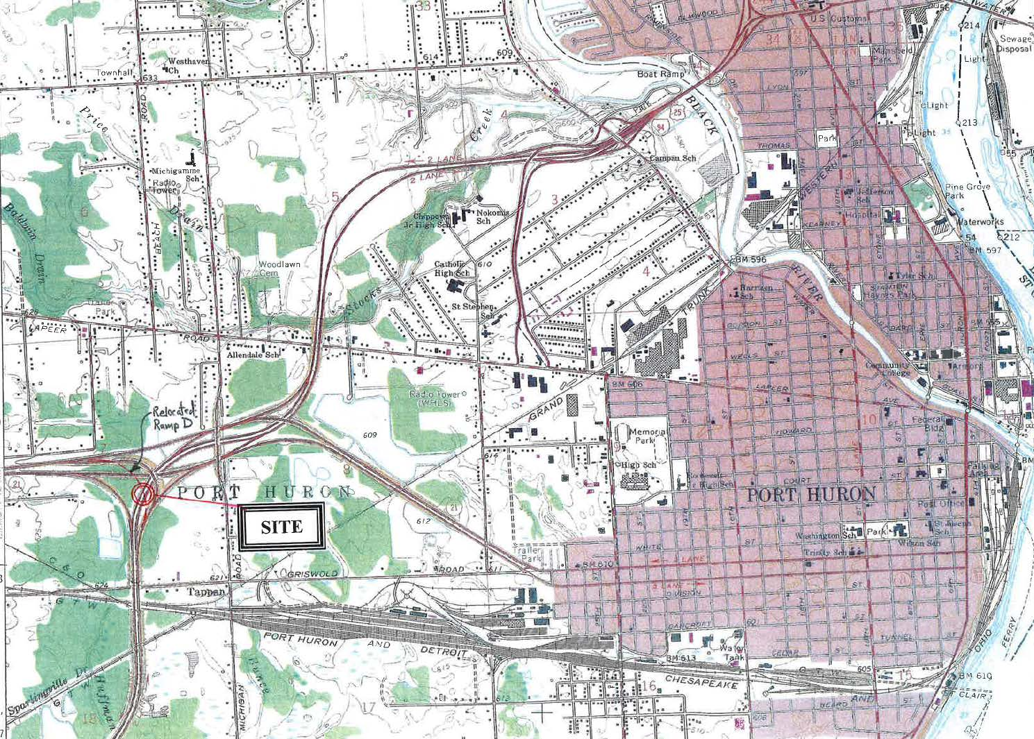
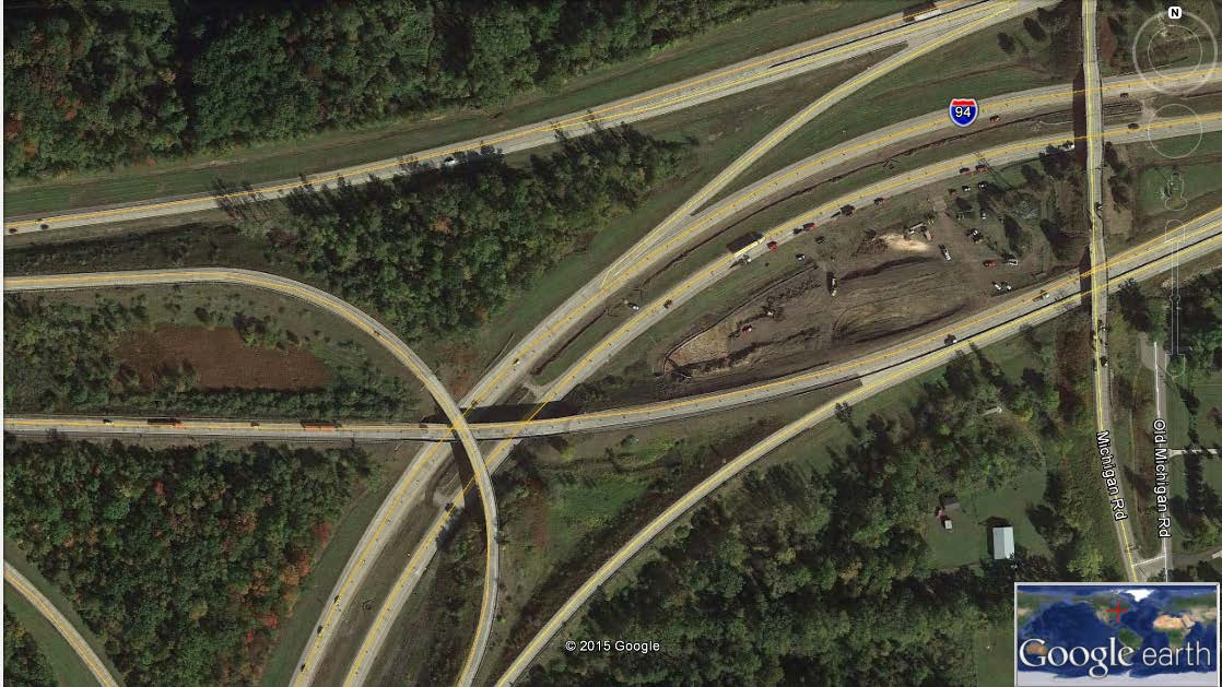
4 Example Bridge

5 Evaluate Existing Test Hole Data Not much before 1940 MDOT Housel Soil Mechanics s ASTM SPT N-modified values
6 Evaluate Existing Test Hole Data Not much before 1940 MDOT Housel Soil Mechanics s ASTM SPT N-modified values

7 Evaluate Existing Test Hole Data Not much before 1940 MDOT Housel Soil Mechanics s ASTM SPT N-modified values
8 New Test Holes
9 In-Situ Vane-shear and 3 Shelby Tubes
10
11
12 Design Shear Strength Profiles 4* Sc old MDOT Vane only Final Selection UC only Used for: Global Stability, Bearing Capacity, Piling Side Resistance, Pile Lateral..
13
14
15 Used for Piling Tip Resistance
16 External Stability Task 1: Lateral Squeeze Task 2: Global Stability Task 3: Settlement Analyses Task 4:Bearing Capacity
17 LATERAL SQUEEZE ANALYSIS FS = 2*Cu + (4.14*Cu) gama*ds*tan(theta) H*gama Also used in the past H*gama < 3Cu, or 4Cu Where, Cu = Undrained shear strength of soft layer, psf Ds = Thickness of soft soil layer, ft gama = Unit weight of fill soil, psf theta = Angle of fill slope, degrees H = Height of fill, ft

18 Primary Shear
19 Secondary/Sympathy Shear

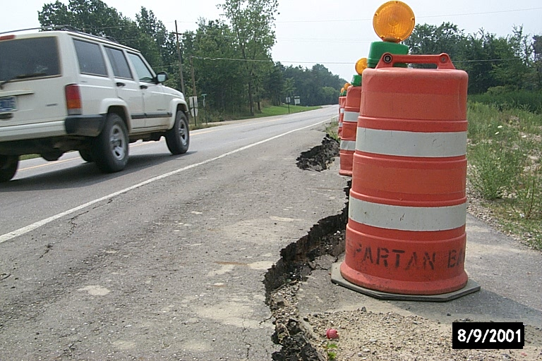
20 Edge of Recent Fill Laterally Squeezed Bulging Uplift Area
21 Previous Scenario H = 6 to 7 feet
22 Utility Contractor Adds Weight
23 Reaches F.S. = 1.0 Condition Road Centerline E.O.M.
24 Failure Backcalculation FS = 2*Cu + (4.14*Cu) gama*ds*tan(theta) H*gama Component 1 Component 2 FS Cu = 180 psf Ds = 30 ft For FS = 1 gama = 125 pcf 3*Cu = 540 theta = 45 degrees 4*Cu = 720 H = 6.5 ft gama*h = 812.5
25 Example Bridge
26 FS = 2*Cu + (4.14*Cu) gama*ds*tan(theta) H*gama Component 1 Component 2 FS Cu = 2100 psf Ds = 100 ft gama = 120 pcf 3*Cu = 6300 theta = 88 degrees 4*Cu = 8400 H = 46 ft gama*h = 5520 Cu FS Calculated F.S. Lateral Squeeze Abut. B Abut. A Undrained Shear strength, Cu, psf Where, Cu = Undrained shear strength of soft layer, psf Ds = Thickness of soft soil layer, ft gama = Unit weight of fill soil, psf theta = Angle of fill slope, degrees H = Height of fill, ft

27 Abutment A GLOBAL STABILITY ANALYSIS
28 Abutment A Set 2% strain force > 1.1 FS force

29 Abutment A Set ultimate force > 1.3 FS force

30 Abutment A Set Grid Limits > 1.54 FS force
31 Change in Plan Decided to add-a-span, use short pile-supported abutment, on 25+ feet of fill instead of the tall full-height abutment

32 Abutment A
33 Abutment B

34 Abutment B

35 Abutment B

36 Abutment B
37 ARE SPREAD FOOTINGS OK? Bearing Capacity
38 ARE SPREAD FOOTINGS OK? Bearing Capacity Factored B.C. = approx psf Approach Embankment Weight next to Abutment: Abut. A = 48*125 = 6000 psf not likely! Abut. B = 30 * 125 = 3750 psf maybe
39 ARE SPREAD FOOTINGS OK? Settlement Management Need to estimate settlement of footings caused by approach embankments And Footing pressures causing settlement serviceability-limit (1-inch and 1.5-inch limits) Pre-loads? Lightweight Fills? Pile Downdrag?

40 SETTLEMENT MANAGEMENT

41 SETTLEMENT MANAGEMENT
42 Elevation, ft Pressure, psf Groundwater Table Today s Condition P0, Overburden
43 615 Pressure, psf Lake Stanley Dry Period Elevation, ft 590 P0, Overburden Glacial Lake Stanley Groundwater Table 515
44 Elevation, ft Pressure, psf Pseudo-Pc P0, Overburden Preconsolidation Glacial Lake Stanley Pc Assumption Ice Weight on Hard Till 515
45 615 Pressure, psf Load Effects Elevation, ft P0, Overburden Glacial Lake Stanley Footing Pressure Pc Assumption P0 + DP
46 615 Pressure, psf Settlement, in Elevation, ft 590 P0, Overburden Glacial Lake Stanley Footing Pressure Pc Assumption P0 + DP Elevation, ft 590 Uc = 100% Uc = 75% Uc = 50% Uc = 25%
47

48 SETTLEMENT MANAGEMENT

49 Wick Drains

50 Wick Drains

51

52 Wick Drains
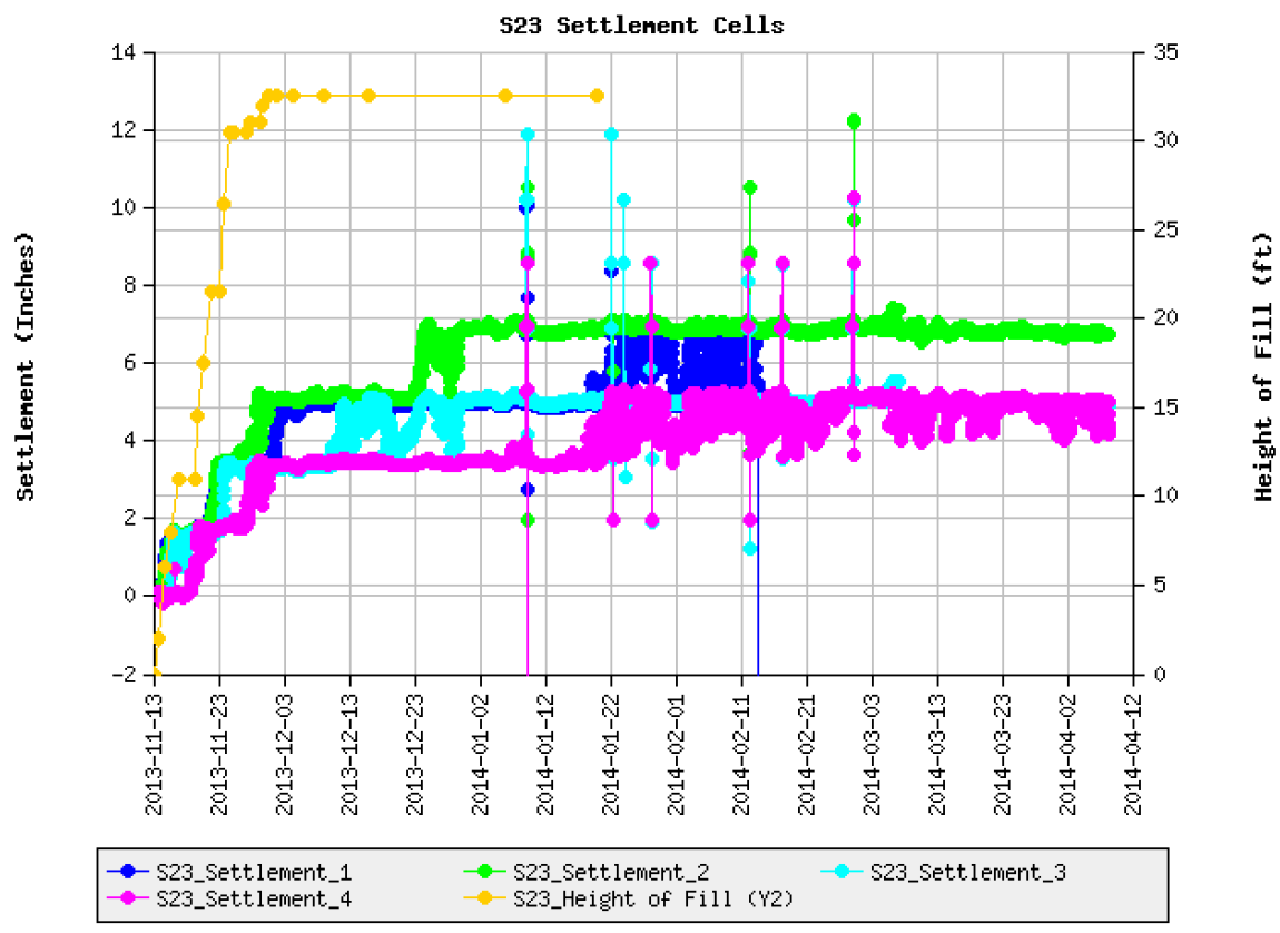
53 Example Bridge (5-20 years w/o wicks) 6 8 Settlement Estimates Soil Only, no footing pressures
54 Change in Plan Wick Drains Installed through Sand Drainage Layer
55 Change in Plan Pre-Load to this Elev. 7 (6 month wait for T90) Settlement Estimates
56 Change in Plan EPS Block H-Piles Less than 0.4 remains (ZERO Downdrag!!!!!) Settlement Estimates

57 Placement of EPS and Geogrid behind sheeting.
58 Example Bridge
59 Wick Drains Installed through Sand Drainage Layer
60 Pre-Load to Full Height (2 month wait) 7 Settlement Estimates
61 Remove Pre-Load, Piles, and Partial EPS EPS Block Est. Settlement =60% of all-sand pre-load

62
63
64 Piling Analyses Axial Resistance Lateral Resistance: batter vs COM624P Bridge Approach Fill Settlement Downdrag Negative Skin Friction
65 Axial Capacity: Driven into Shale Rock With about 400 Kip Side Resistance 100+ kip Tip/Bottom Resistance HP14x73

66
67
68
69
70 0.4 settlement
71 615 Pressure, psf " Settlement, in Elevation, ft 590 P0, Overburden Glacial Lake Stanley Footing Pressure Pc Assumption P0 + DP Elevation, ft 590 Uc = 100% Uc = 75% Uc = 50% Uc = 25% kip kip 350 kip 360 kip
72 615 Pressure, psf " 0.5" Settlement, in Elevation, ft 590 P0, Overburden Glacial Lake Stanley Footing Pressure Pc Assumption P0 + DP Elevation, ft 590 Uc = 100% Uc = 75% Uc = 50% Uc = 25% kip 250 kip kip 320 kip 340 kip 350 kip 355 kip 360 kip An extra 0.1 allowance for elastic pile shortening.
73
74 For R ndr = 500 kip HP14x73, 25% settlement remaining: R n = (250/400) = kips Q p = 0.75(362.5) 220 = 52 kips/pile OUCH!!!! Drive 500 kip pile, only 52 kip available for bridge weight!!! NO GO!!
75 PDA with Dynamic Signal Matching Dynamic Static Rs = 400 kips R sdd = 250/400(DD) reduced side resistance during driving
76 615 Pressure, psf " 0.5" Settlement, in Elevation, ft 590 P0, Overburden Glacial Lake Stanley Footing Pressure Pc Assumption P0 + DP Elevation, ft 590 Uc = 100% Uc = 75% Uc = 50% Uc = 25% kip 250 kip kip 320 kip 340 kip 350 kip 355 kip 360 kip An extra 0.1 allowance for elastic pile shortening.
77 180 Pile Lateral Resistance COM624P LPILE Depth Below Footing, in Lateral Deflection, in Lateral Load 9-kip 15-kip 20-kip kip 30-kip
78 From LPILE Technical Manual
79 P = soil pressure V Q M W p From LPILE Technical Manual
80 List of Recs Given To Bridge Engineer Global Stability Settlement Amounts and Rates Spreads versus Deep Foundations Lateral Resistances Special Provisions/Materials Specifications Construction Considerations Water control Surface preparation Temporary Walls Vibrations Geotechnical Instrumentation needed?
81 Doug Parmerlee Overview of Abutment Design Concepts
82 Geotechnical Engineering During Construction
83 Geotechnical Field Monitoring Pile Axial Capacity Settlement Rates and Amounts Geosynthetics: Limits/Continuity/Splicing Lightweight Fills: Limits/Materials
84 PDA with Dynamic Signal Matching

85 Static Pile Load Tests

86 Soil Pore Pressure Dissipation
87
88

89 Ancient Glacial Lake Beach on top of Grand Portal Point, Pictured Rocks Michigan s State Fossil: Mastodon M = EI d 2 z 2 dx
Geotechnical Measurements and Explorations Prof. Nihar Ranjan Patra Department of Civil Engineering Indian Institute of Technology, Kanpur
 Geotechnical Measurements and Explorations Prof. Nihar Ranjan Patra Department of Civil Engineering Indian Institute of Technology, Kanpur Lecture No. # 13 (Refer Slide Time: 00:18) So last class, it was
How to Design and Build a Fence/G traverse Bridge or Graffiti Project
 Outline Project Location Project Description Project History Site Constraints Geotechnical Investigation & Soil Profile Foundation Design Process Photos Project Location Project Limits: The Grand River
FOUNDATION DESIGN. Instructional Materials Complementing FEMA 451, Design Examples
 FOUNDATION DESIGN Proportioning elements for: Transfer of seismic forces Strength and stiffness Shallow and deep foundations Elastic and plastic analysis Foundation Design 14-1 Load Path and Transfer to
How To Model A Shallow Foundation
 Finite Element Analysis of Elastic Settlement of Spreadfootings Founded in Soil Jae H. Chung, Ph.D. Bid Bridge Software Institute t University of Florida, Gainesville, FL, USA Content 1. Background 2.
PILE FOUNDATIONS FM 5-134
 C H A P T E R 6 PILE FOUNDATIONS Section I. GROUP BEHAVIOR 6-1. Group action. Piles are most effective when combined in groups or clusters. Combining piles in a group complicates analysis since the characteristics
Use and Application of Piezocone Penetration Testing in Presumpscot Formation
 Use and Application of Piezocone Penetration Testing in Presumpscot Formation Craig W. Coolidge, P.E. Summit Geoengineering Services, Rockland, Maine ABSTRACT: This paper examines the advantages and limitations
Value of Instrumentation Systems and Real-Time Monitoring: An Owner s Perspective
 Value of Instrumentation Systems and Real-Time Monitoring: An Owner s Perspective FHWA NATIONAL GEOTECHNICAL PROGRAM www.fhwa.dot.gov/engineering/geotech Why Geotechnical Instrumentation? Provide warning
Kentucky Lake Bridge Pile Load Testing Overview Ohio Transportation Engineering Conference Columbus, Ohio 10/28/2015
 Kentucky Lake Bridge Pile Load Testing Overview Ohio Transportation Engineering Conference Columbus, Ohio 10/28/2015 Presented by: Jeff Dunlap, P.E. Terracon Consultants 1 Project Site Kentucky Official
ENCE 4610 Foundation Analysis and Design
 This image cannot currently be displayed. ENCE 4610 Foundation Analysis and Design Shallow Foundations Total and Differential Settlement Schmertmann s Method This image cannot currently be displayed. Strength
Table of Contents 16.1 GENERAL... 16.1-1. 16.1.1 Overview... 16.1-1 16.1.2 Responsibilities... 16.1-1
 Table of Contents Section Page 16.1 GENERAL... 16.1-1 16.1.1 Overview... 16.1-1 16.1.2 Responsibilities... 16.1-1 16.1.2.1 Geotechnical Section/Bridge Bureau Coordination... 16.1-1 16.1.2.2 Geotechnical
VERTICAL MICROPILE LATERAL LOADING. Andy Baxter, P.G.
 EFFICIENT DESIGN OF VERTICAL MICROPILE SYSTEMS TO LATERAL LOADING Dr. Jesús Gómez, P.E. PE Andy Baxter, P.G. Outline When are micropiles subject to lateral load? How do we analyze them? Shear Friction
Strength Determination of "Tooth-Paste" Like Sand and Gravel Washing Fines Using DMT
 Strength Determination of "Tooth-Paste" Like Sand and Gravel Washing Fines Using DMT David L. Knott, P.E. and James M. Sheahan, P.E. HDR Engineering, Inc. 3 Gateway Center Pittsburgh, PA 15222-1074 Phone:
Eurocode 7 - Geotechnical design - Part 2 Ground investigation and testing
 Brussels, 18-20 February 2008 Dissemination of information workshop 1 Eurocode 7 - Geotechnical design - Part 2 Ground investigation and testing Dr.-Ing. Bernd Schuppener, Federal Waterways Engineering
BRIDGE RESTORATION AND LANDSLIDE CORRECTION USING STRUCTURAL PIER AND GRADE BEAM
 BRIDGE RESTORATION AND LANDSLIDE CORRECTION USING STRUCTURAL PIER AND GRADE BEAM Swaminathan Srinivasan, P.E., M.ASCE H.C. Nutting/Terracon David Tomley, P.E., M.ASCE KZF Design Delivering Success for
Micropiles Reduce Costs and Schedule for Merchant RR Bridge Rehabilitation
 Micropiles Reduce Costs and Schedule for Merchant RR Bridge Rehabilitation Jeff R. Hill, P.E. Hayward Baker Inc. 111 W. Port Plaza Drive Suite 600 St. Louis, MO 63146 314-542-3040 JRHill@HaywardBaker.com
DESIGN OF PILES AND PILE GROUPS CONSIDERING CAPACITY, SETTLEMENT, AND NEGATIVE SKIN FRICTION
 DESIGN OF PILES AND PILE GROUPS CONSIDERING CAPACITY, SETTLEMENT, AND NEGATIVE SKIN FRICTION Introduction Bengt H. Fellenius, Dr.Tech., P.Eng. Background Notes for Demo Example for UniPile at www.unisoftltd.com
Dynamic Load Testing of Helical Piles
 Dynamic Load Testing of Helical Piles ANNUAL KANSAS CITY SPECIALTY SEMINAR 2014 JANUARY 10, 2014 Jorge Beim JWB Consulting LLC Pile Dynamics, Inc. Main Topics Brief description of the Dynamic Load Test
Earth Pressure and Retaining Wall Basics for Non-Geotechnical Engineers
 PDHonline Course C155 (2 PDH) Earth Pressure and Retaining Wall Basics for Non-Geotechnical Engineers Instructor: Richard P. Weber, P.E. 2012 PDH Online PDH Center 5272 Meadow Estates Drive Fairfax, VA
Outline MICROPILES SUBJECT TO LATERAL LOADING. Dr. Jesús Gómez, P.E.
 MICROPILES SUBJECT TO LATERAL LOADING Dr. Jesús Gómez, P.E. Micropile Design and Construction Seminar Las Vegas, NV April 3-4, 2008 Outline When are micropiles subject to lateral load? How do we analyze
PDCA Driven-Pile Terms and Definitions
 PDCA Driven-Pile Terms and Definitions This document is available for free download at piledrivers.org. Preferred terms are descriptively defined. Potentially synonymous (but not preferred) terms are identified
2009 Japan-Russia Energy and Environment Dialogue in Niigata S2-6 TANAKA ERINA
 Importance of the Site Investigation for Development of Methane Hydrate Hokkaido University Hiroyuki Tanaka Civil Engineer My Background Site Investigation Soil Parameters for Design Very Soft Clay and
vulcanhammer.net This document downloaded from
 This document downloaded from vulcanhammer.net since 1997, your source for engineering information for the deep foundation and marine construction industries, and the historical site for Vulcan Iron Works
Design, Testing and Automated Monitoring of ACIP Piles in Residual Soils
 Design, Testing and Automated Monitoring of ACIP Piles in Residual Soils Stephen W. Lacz 1, M. ASCE, P.E. and Richard C. Wells 2, F. ASCE, P.E. 1 Senior Professional, Trigon Kleinfelder, Inc., 313 Gallimore
STRUCTURES. 1.1. Excavation and backfill for structures should conform to the topic EXCAVATION AND BACKFILL.
 STRUCTURES 1. General. Critical structures may impact the integrity of a flood control project in several manners such as the excavation for construction of the structure, the type of foundation, backfill
EXAMPLE 1 DESIGN OF CANTILEVERED WALL, GRANULAR SOIL
 EXAMPLE DESIGN OF CANTILEVERED WALL, GRANULAR SOIL A sheet pile wall is required to support a 2 excavation. The soil is uniform as shown in the figure. To take into account the friction between the wall
REINFORCED CONCRETE. Reinforced Concrete Design. A Fundamental Approach - Fifth Edition. Walls are generally used to provide lateral support for:
 HANDOUT REINFORCED CONCRETE Reinforced Concrete Design A Fundamental Approach - Fifth Edition RETAINING WALLS Fifth Edition A. J. Clark School of Engineering Department of Civil and Environmental Engineering
5/1/2013. Topics. The challenge is to better maintain native characteristics of soils during and after construction
 PIN Foundations Topics Applications Design and Construction Flow Control Credits www.pinfoundations.com Copyright 2008, Pin Foundations, Inc. Curtis Hinman WSU Extension Faculty, Watershed Ecologist chinman@wsu.edu
Table of Contents. July 2015 12-1
 Table of Contents 12.1 General... 3 12.2 Abutment Types... 5 12.2.1 Full-Retaining... 5 12.2.2 Semi-Retaining... 6 12.2.3 Sill... 7 12.2.4 Spill-Through or Open... 7 12.2.5 Pile-Encased... 8 12.2.6 Special
CONCRETE SEGMENTAL RETAINING WALL SYSTEM
 CONCRETE SEGMENTAL RETAINING WALL SYSTEM PART 1: GENERAL SPECIFICATIONS 1.01 Work Included A. Work shall consist of furnishing and constructing a Rockwood Classic 8 with PCS unit segmental retaining wall
Engineered, Time-Tested Foundation Repairs for Settlement in Residential and Light Commercial Structures. The Leading Edge.
 TM TM Engineered, Time-Tested Foundation Repairs for Settlement in Residential and Light Commercial Structures. SM The Leading Edge. 10 One Major Causes of foundation settlement or more conditions may
GLOSSARY OF TERMINOLOGY
 GLOSSARY OF TERMINOLOGY AUTHORIZED PILE LENGTHS - (a.k.a. Authorized Pile Lengths letter) Official letter stating Engineer's recommended length of concrete piles to be cast for construction of foundation.
Instrumentations, Pile Group Load Testing, and Data Analysis Part II: Design & Analysis of Lateral Load Test. Murad Abu-Farsakh, Ph.D., P.E.
 Instrumentations, Pile Group Load Testing, and Data Analysis Part II: Design & Analysis of Lateral Load Test Murad Abu-Farsakh, Ph.D., P.E. Louisiana Transportation Research Center Louisiana State University
CONCRETE SEGMENTAL RETAINING WALL SYSTEM
 CONCRETE SEGMENTAL RETAINING WALL SYSTEM PART 1: GENERAL SPECIFICATIONS 1.01 Work Included A. Work shall consist of furnishing and constructing a Rockwood Vintage TM unit segmental retaining wall (SRW)
SPECIFICATIONS FOR PRECAST MODULAR BLOCK RETAINING WALL SYSTEM (revised 11/5/13)
") Page 1 of 7 STONE STRONG SYSTEMS SPECIFICATIONS FOR PRECAST MODULAR BLOCK RETAINING WALL SYSTEM (revised ) PART 1: GENERAL 1.01 Description A. Work includes furnishing and installing precast modular blocks
Page 1 of 7 STONE STRONG SYSTEMS SPECIFICATIONS FOR PRECAST MODULAR BLOCK RETAINING WALL SYSTEM (revised ) PART 1: GENERAL 1.01 Description A. Work includes furnishing and installing precast modular blocks
ANNEX D1 BASIC CONSIDERATIONS FOR REVIEWING STUDIES IN THE DETAILED RISK ASSESSMENT FOR SAFETY
 ANNEX D1 BASIC CONSIDERATIONS FOR REVIEWING STUDIES IN THE DETAILED RISK ASSESSMENT FOR SAFETY ANNEX D1: BASIC CONSIDERATIONS FOR REVIEWING STUDIES IN DRA FOR SAFETY D1-1 ANNEX D1 BASIC CONSIDERATIONS
Step 11 Static Load Testing
 Step 11 Static Load Testing Test loading is the most definitive method of determining load capacity of a pile. Testing a pile to failure provides valuable information to the design engineer and is recommended
High Strain Dynamic Load Testing of Drilled Shafts
 Supplemental Technical Specification for High Strain Dynamic Load Testing of Drilled Shafts SCDOT Designation: SC-M-712 (9/15) September 3, 2015 1.0 GENERAL This work shall consist of performing high-strain
c. Borehole Shear Test (BST): BST is performed according to the instructions published by Handy Geotechnical Instruments, Inc.
: BST is performed according to the instructions published by Handy Geotechnical Instruments, Inc.") Design Manual Chapter 6 - Geotechnical 6B - Subsurface Exploration Program 6B-2 Testing A. General Information Several testing methods can be used to measure soil engineering properties. The advantages,
Design Manual Chapter 6 - Geotechnical 6B - Subsurface Exploration Program 6B-2 Testing A. General Information Several testing methods can be used to measure soil engineering properties. The advantages,
EN 1997-1 Eurocode 7. Section 10 Hydraulic Failure Section 11 Overall Stability Section 12 Embankments. Trevor L.L. Orr Trinity College Dublin Ireland
 EN 1997 1: Sections 10, 11 and 12 Your logo Brussels, 18-20 February 2008 Dissemination of information workshop 1 EN 1997-1 Eurocode 7 Section 10 Hydraulic Failure Section 11 Overall Stability Section
CEEN 162 - Geotechnical Engineering Laboratory Session 7 - Direct Shear and Unconfined Compression Tests
 PURPOSE: The parameters of the shear strength relationship provide a means of evaluating the load carrying capacity of soils, stability of slopes, and pile capacity. The direct shear test is one of the
SECTION 5: SANITARY SEWER SYSTEM DESIGN
 SECTION 5: SANITARY SEWER SYSTEM DESIGN 5.01 GENERAL Sanitary sewer improvements shall be designed to serve the ultimate level of City development as defined in the General Plan and the Wastewater Facilities
DIRT DWELLING. and your. www.pinfoundations.com. Pin Foundations Inc., 2008
 DIRT and your DWELLING 2008 Pin Foundations Inc., 2008 If we accept that preserving soil in its native condition is necessary, then how do we build? Utilities? Roads? Foundations? Typical Strip, Transfer,
The demand for new roadway
 Designing strong walls on weak soils Civil engineers have options to remedy foundation soil problems and meet project cost and schedule requirements. By Fadi Faraj, P.E.; Michael H. Garrison, P.E.; and
CIVL451. Soil Exploration and Characterization
 CIVL451 Soil Exploration and Characterization 1 Definition The process of determining the layers of natural soil deposits that will underlie a proposed structure and their physical properties is generally
DFI CSCE Workshop April 12, 2013 Solutions for Embankments Over Soft Soils Embankments Over Soft Soils
 DFI CSCE Workshop April 12, 2013 Solutions for Embankments Over Soft Soils Embankments Over Soft Soils Construction over Unstable Soils focuses on methods to support embankment and embankment widening
REPORT OF GEOTECHNICAL EXPLORATION BRIDGE STRUCTURE REPORT
 REPORT OF GEOTECHNICAL EXPLORATION BRIDGE STRUCTURE REPORT New Wolf Pen Branch Road Bridge and Temporary Diversion Bridge LSIORBP Section 4 KY 841 Louisville, Jefferson County, Kentucky KSWA Project No.
CHAPTER 6 SETTLEMENT ANALYSES
 CHAPTER 6 SETTLEMENT ANALYSES This chapter provides information to use when analyzing the potential for failure due to settlement at an Ohio waste containment facility. It is important to account for settlement
METHOD OF STATEMENT FOR STATIC LOADING TEST
 Compression Test, METHOD OF STATEMENT FOR STATIC LOADING TEST Tension Test and Lateral Test According to the American Standards ASTM D1143 07, ASTM D3689 07, ASTM D3966 07 and Euro Codes EC7 Table of Contents
1. ASTM C 140 - Sampling and Testing Concrete Masonry Units 2. ASTM C 1372 Standard Specification for Dry-Cast Segmental Retaining Wall Units
 SPECIFICATION FOR SEGMENTAL RETAINING WALL SYSTEMS PART 1: GENERAL 1.01 Description A. Work shall consist of furnishing materials, labor, equipment and supervision to install a segmental retaining wall
Drained and Undrained Conditions. Undrained and Drained Shear Strength
 Drained and Undrained Conditions Undrained and Drained Shear Strength Lecture No. October, 00 Drained condition occurs when there is no change in pore water pressure due to external loading. In a drained
Comprehensive Design Example 2: Foundations for Bulk Storage Facility
 Comprehensive Design Example 2: Foundations for Bulk Storage Facility Problem The project consists of building several dry product storage silos near an existing rail siding in an open field presently
CHAPTER 9 FEM MODELING OF SOIL-SHEET PILE WALL INTERACTION
 391 CHAPTER 9 FEM MODELING OF SOIL-SHEET PILE WALL INTERACTION 9.1 OVERVIEW OF FE SOIL-STRUCTURE INTERACTION Clough and Denby (1969) introduced Finite Element analysis into the soil-structure interaction
COMPENDIUM OF INDIAN STANDARDS ON SOIL ENGINEERING PART 2
 (PREVIEW) SP 36 (Part 2) : 1988 COMPENDIUM OF INDIAN STANDARDS ON SOIL ENGINEERING PART 2 IS 1893 : 1979 (Reaffirmed 1987) CODE OF PRACTICE FOR SUBSURFACE INVESTIGATION FOR FOUNDATIONS 1.1 This code deals
vulcanhammer.net This document downloaded from
 This document downloaded from vulcanhammer.net since 1997, your source for engineering information for the deep foundation and marine construction industries, and the historical site for Vulcan Iron Works
Numerical Analysis of Texas Cone Penetration Test
 International Journal of Applied Science and Technology Vol. 2 No. 3; March 2012 Numerical Analysis of Texas Cone Penetration Test Nutan Palla Project Engineer, Tolunay-Wong Engineers, Inc. 10710 S Sam
SUPPLEMENTAL TECHNICAL SPECIFICATIONS BI-DIRECTIONAL STATIC LOAD TESTING OF DRILLED SHAFTS
 July 14, 2015 1.0 GENERAL BI-DIRECTIONAL STATIC LOAD TESTING OF DRILLED SHAFTS This work shall consist of furnishing all materials, equipment, labor, and incidentals necessary for conducting bi-directional
RECENT ADVANCES IN THE DESIGN OF PILES FOR AXIAL LOADS, DRAGLOADS, DOWNDRAG, AND SETTLEMENT
 RECENT ADVANCES IN THE DESIGN OF PILES FOR AXIAL LOADS, DRAGLOADS, DOWNDRAG, AND SETTLEMENT ASCE and Port of NY&NJ Seminar 1), April 22 and 23, 1998 Bengt H. Fellenius Urkkada Technology Ltd. Ottawa, Ontario
The Installation and Load Testing of Drilled Shafts
 Presentation to the North American Chinese Geotechnical Engineers Association The Installation and Load Testing of Drilled Shafts at Clarksville, Virginia by James M. Sheahan, P.E. HDR Engineering, Inc.
Lymon C. Reese & Associates LCR&A Consulting Services Tests of Piles Under Axial Load
 Lymon C. Reese & Associates LCR&A Consulting Services Tests of Piles Under Axial Load Nature of Services The company has a long history of performance of tests of piles and pile groups under a variety
Period #16: Soil Compressibility and Consolidation (II)
") Period #16: Soil Compressibility and Consolidation (II) A. Review and Motivation (1) Review: In most soils, changes in total volume are associated with reductions in void volume. The volume change of the
Period #16: Soil Compressibility and Consolidation (II) A. Review and Motivation (1) Review: In most soils, changes in total volume are associated with reductions in void volume. The volume change of the
1997 Uniform Administrative Code Amendment for Earthen Material and Straw Bale Structures Tucson/Pima County, Arizona
 for Earthen Material and Straw Bale Structures SECTION 70 - GENERAL "APPENDIX CHAPTER 7 - EARTHEN MATERIAL STRUCTURES 70. Purpose. The purpose of this chapter is to establish minimum standards of safety
Chapter 4 SUBSURFACE INVESTIGATION GUIDELINES
 Chapter 4 SUBSURFACE INVESTIGATION GUIDELINES Final SCDOT GEOTECHNICAL DESIGN MANUAL August 2008 Table of Contents Section Page 4.1 Introduction...4-1 4.2 Subsurface Investigation...4-2 4.2.1 Preliminary
CH. 2 LOADS ON BUILDINGS
 CH. 2 LOADS ON BUILDINGS GRAVITY LOADS Dead loads Vertical loads due to weight of building and any permanent equipment Dead loads of structural elements cannot be readily determined b/c weight depends
Design and Construction of Auger Cast Piles
 Design and Construction of Auger Cast Piles 101 th Annual Road School 2015 3/11/2015 Malek Smadi, Ph.D., P.E. Principal Engineer - GEOTILL - Fishers, IN msmadi@geotill.com - www.geotill.com CONTENTS 1.
Anirudhan I.V. Geotechnical Solutions, Chennai
 Anirudhan I.V. Geotechnical Solutions, Chennai Often inadequate In some cases, excess In some cases, disoriented Bad investigation Once in a while good ones Depends on one type of investigation, often
Ohio Department of Transportation Division of Production Management Office of Geotechnical Engineering. Geotechnical Bulletin PLAN SUBGRADES
 Ohio Department of Transportation Division of Production Management Office of Geotechnical Engineering Geotechnical Bulletin GB 1 PLAN SUBGRADES Geotechnical Bulletin GB1 was jointly developed by the Offices
FOUNDATION INVESTIGATIONS FOR STRUCTURES
 FOUNDATION INVESTIGATIONS FOR STRUCTURES 6 INDEX Page I. Overview of MoDOT Practice 1 A. Geotechnical Organization of MoDOT 1 B. Types of Reports 1 C. Special Investigations 2 II. Policy Manuals 3 A. Materials
Washington 98102-3699, mike.bailey@hartcrowser.com
 LESSONS LEARNED FROM A STONE COLUMN TEST PROGRAM IN GLACIAL DEPOSITS Barry S. Chen 1, P.E., Member, Geo-Institute and Michael J. Bailey 2, P.E., Member, Geo-Institute ABSTRACT A stone column test program
Emergency repair of Bridge B421
 Emergency repair of Bridge B421 over the Olifants River after fl ood damage INTRODUCTION AND BACKGROUND Bridge B421 is located on the R555 at km 5.03 on Section 01E between Witbank (now known as emalahleni)
Civil. 2. City of Seattle Supplement to the Specification for Road, Bridge and Municipal Construction, most current addition.
 Design Guide Basis of Design This section applies to the design and installation of earthwork and backfill. Design Criteria No stockpiling of excavation materials is allowed unless the Geotechnical Engineer
State of Illinois Department Of Transportation CONSTRUCTION INSPECTOR S CHECKLIST FOR STORM SEWERS
 State of Illinois Department Of Transportation CONSTRUCTION INSPECTOR S CHECKLIST FOR STORM SEWERS While its use is not required, this checklist has been prepared to provide the field inspector a summary
SECTION 1 GENERAL REQUIREMENTS
 Page 1 of 6 SECTION 1 GENERAL REQUIREMENTS 1. SCOPE OF WORK: The work to be performed under the provisions of these documents and the contract based thereon includes furnishing all labor, equipment, materials,
ALLOWABLE LOADS ON A SINGLE PILE
 C H A P T E R 5 ALLOWABLE LOADS ON A SINGLE PILE Section I. BASICS 5-1. Considerations. For safe, economical pile foundations in military construction, it is necessary to determine the allowable load capacity
UPDATED 14 JUN 12 3.1 DESIGN PROCEDURE FOR EARTHEN EMBANKMENTS
 3.0 GEOTECHNICAL 3.1 DESIGN PROCEDURE FOR EARTHEN EMBANKMENTS The following represents the typical procedure for the geotechnical design and analysis of levee embankments. The procedures stated herein,
CHAPTER 9 LONG TERM MONITORING AT THE ROUTE 351 BRIDGE
 CHAPTER 9 LONG TERM MONITORING AT THE ROUTE 351 BRIDGE 9.1 INTRODUCTION An important reason that composite piles have not gained wide acceptance in the civil engineering practice is the lack of a long
STANDARD REQUIREMENTS FOR BONDING OR MECHANICAL ATTACHMENT OF INSULATION PANELS AND MECHANICAL ATTACHMENT OF ANCHOR AND/OR BASE SHEETS TO SUBSTRATES
 ROOFING APPLICATION STANDARD (RAS) No. 117 STANDARD REQUIREMENTS FOR BONDING OR MECHANICAL ATTACHMENT OF INSULATION PANELS AND MECHANICAL ATTACHMENT OF ANCHOR AND/OR BASE SHEETS TO SUBSTRATES Scope 1.1.
Stability. Security. Integrity.
 Stability. Security. Integrity. PN #MBHPT Foundation Supportworks provides quality helical pile systems for both new construction and retrofit applications. 288 Helical Pile System About Foundation Supportworks
COSMOS 2012: Earthquakes in Action COSMOS 2012
 COSMOS 2012 What is SFSI and why is it important? Soil issues in Earthquakes Structures where SFSI important Retaining structures (lateral earth pressure) Foundations (spread and pile footings, bearing
INSITU TESTS! Shear Vanes! Shear Vanes! Shear Vane Test! Sensitive Soils! Insitu testing is used for two reasons:!
 In-situ Testing! Insitu Testing! Insitu testing is used for two reasons:! To allow the determination of shear strength or penetration resistance or permeability of soils that would be difficult or impossible
Design of pile foundations following Eurocode 7-Section 7
 Brussels, 18-20 February 2008 Dissemination of information workshop 1 Workshop Eurocodes: background and applications Brussels, 18-20 Februray 2008 Design of pile foundations following Eurocode 7-Section
System. Stability. Security. Integrity. 150 Helical Anchor
 Model 150 HELICAL ANCHOR System PN #MBHAT Stability. Security. Integrity. 150 Helical Anchor System About Foundation Supportworks is a network of the most experienced and knowledgeable foundation repair
Cone Penetration Testing in Geotechnical Practice. Tom Lunne Peter K. Robertson John J.M. Powell
 Cone Penetration Testing in Geotechnical Practice Tom Lunne Peter K. Robertson John J.M. Powell BLACKIE ACADEMIC & PROFESSIONAL An Imprint of Chapman & Hall London Weinheim New York Tokyo Melbourne Madras
New construction Repairing failed or old foundations Retrofit foundations Permanent battered piers Machinery/equipment foundations
 from New construction foundations don t have to be a headache. The CHANCE Helical Pier Foundation System gives you the performance of concrete without the drawbacks and liabilities of driven piles and
Formwork for Concrete
 UNIVERSITY OF WASHINGTON DEPARTMENT OF CONSTRUCTION MANAGEMENT CM 420 TEMPORARY STRUCTURES Winter Quarter 2007 Professor Kamran M. Nemati Formwork for Concrete Horizontal Formwork Design and Formwork Design
SETTLEMENT OF EMBANKMENT DAMS DON T FORGET ABOUT THE BEDROCK. Abstract
 SETTLEMENT OF EMBANKMENT DAMS DON T FORGET ABOUT THE BEDROCK By: Robert J. Huzjak, P.E. (1), and Adam B. Prochaska, Ph.D., E.I. (2) Abstract Predicting deformation of embankment dams and ancillary facilities
Laterally Loaded Piles
 Laterally Loaded Piles 1 Soil Response Modelled by p-y Curves In order to properly analyze a laterally loaded pile foundation in soil/rock, a nonlinear relationship needs to be applied that provides soil
load on the soil. For this article s examples, load bearing values given by the following table will be assumed.
 How Many Piers? By Gary Collins, P.E. A clear-cut guide to helical pier spacing Introduction Helical pier spacing is not an exact science. How many does it take to support a structure adequately or repair
USE OF MICROPILES IN TEXAS BRIDGES. by John G. Delphia, P.E. TxDOT Bridge Division Geotechnical Branch
 USE OF MICROPILES IN TEXAS BRIDGES by John G. Delphia, P.E. TxDOT Bridge Division Geotechnical Branch DEFINITION OF A MICROPILE A micropile is a small diameter (typically less than 12 in.), drilled and
Figure A-1. Figure A-2. continued on next page... HPM-1. Grout Reservoir. Neat Cement Grout (Very Flowable) Extension Displacement Plate
 Extension Displacement Plate") Addendum HELICAL PULLDOWN Micropile (HPM) Introduction The HPM is a system for constructing a grout column around the shaft of a standard Helical Screw Foundation (see Figure A1). To begin the process,
Addendum HELICAL PULLDOWN Micropile (HPM) Introduction The HPM is a system for constructing a grout column around the shaft of a standard Helical Screw Foundation (see Figure A1). To begin the process,
SPECIFICATION FOR DYNAMIC CONSOLIDATION / DYNAMIC REPLACEMENT
 SPECIFICATION FOR DYNAMIC CONSOLIDATION / DYNAMIC REPLACEMENT 1.0 SOIL IMPROVEMENT 1.1 General Soil Investigation Information are provided in Part B1 annex as a guide to the Contractor for his consideration
Soil Strength. Performance Evaluation of Constructed Facilities Fall 2004. Prof. Mesut Pervizpour Office: KH #203 Ph: x4046
 ENGR-627 Performance Evaluation of Constructed Facilities, Lecture # 4 Performance Evaluation of Constructed Facilities Fall 2004 Prof. Mesut Pervizpour Office: KH #203 Ph: x4046 1 Soil Strength 2 Soil
KWANG SING ENGINEERING PTE LTD
 KWANG SING ENGINEERING PTE LTD 1. INTRODUCTION This report represents the soil investigation works at Aljunied Road / Geylang East Central. The objective of the soil investigation is to obtain soil parameters
SAMPLE GUIDE SPECIFICATIONS FOR OSTERBERG CELL LOAD TESTING OF DEEP FOUNDATIONS
 Page 1 of 9 SAMPLE GUIDE SPECIFICATIONS FOR OSTERBERG CELL LOAD TESTING OF DEEP FOUNDATIONS 1. GENERAL REQUIREMENTS 1. Description of Work: This work consists of furnishing all materials, equipment and
Geotechnical Engineering: Slope Stability
 Geotechnical Engineering: Slope Stability Course No: G06-001 Credit: 6 PDH Yun Zhou, PhD, PE Continuing Education and Development, Inc. 9 Greyridge Farm Court Stony Point, NY 10980 P: (877) 322-5800 F:
Stabilenka HUESKER. and Separation. Engineering with Geosynthetics SKER HUESKER HUESKER HUESKER HUESKERHUES
 HUESKER Engineering with Geosynthetics rhuesker HUESKER HUESKER HUESKER HUESKER HUESKERr rhuesker HUESKER Woven HUESKER HUESKER Fabrics HUESKER HUESKERr SKER HUESKER HUESKER HUESKER HUESKERHUES rhuesker
Multi-stage Pseudo-static Analysis
 Multi-stage Pseudo-static Analysis GEO-SLOPE International Ltd. www.geo-slope.com 14, 633-6th Ave SW, Calgary, AB, Canada T2P 2Y5 Main: +1 43 269 22 Fax: +1 43 266 4851 Introduction It is generally assumed
Dams and Extreme Events Reducing Risk of Aging Infrastructure under Extreme Loading Conditions
 Dams and Extreme Events Reducing Risk of Aging Infrastructure under Extreme Loading Conditions 34th Annual USSD Conference San Francisco, California, April 7-11, 2014 Hosted by San Francisco Public Utilities
How To Design A Foundation
 The Islamic university - Gaza Faculty of Engineering Civil Engineering Department CHAPTER (2) SITE INVESTIGATION Instructor : Dr. Jehad Hamad Definition The process of determining the layers of natural
Site Investigation. Some unsung heroes of Civil Engineering. buried right under your feet. 4. Need good knowledge of the soil conditions
 This is an attempt to create a stand alone self learning module on site investigation. Fasten your seat belts. Sit back, relax and enjoy. 1 2 Site Investigation Some unsung heroes of Civil Engineering
Up-Down Construction Utilizing Steel Sheet Piles and Drilled Shaft Foundations
 Up-Down Construction Utilizing Steel Sheet Piles and Drilled Shaft Foundations Nathan A. Ingraffea, P.E., S.E. Associate, KPFF Consulting Engineers, Portland, Oregon, USA Abstract The use of steel sheet