Analytical Forward Projection for Axial Non-Central Dioptric and Catadioptric Cameras
|
|
|
- Garey Dennis
- 7 years ago
- Views:
Transcription
1 Analytical Forward Projection for Axial Non-Central Dioptric and Catadioptric Cameras Amit Agrawal Yuichi Taguchi Srikumar Ramalingam Mitsubishi Electric Research Labs (MERL)
 Single")
2 Perspective Cameras (Central) Perspective Camera Single Viewpoint (Central) Single Viewpoint
 Hyperbolic Mirror Virtual")
3 Single-Viewpoint Catadioptric Cameras Mirror + Perspective Camera Wide Field of View Perspective Camera Single Viewpoint (Central) Hyperbolic Mirror Virtual Viewpoint
4 Single-Viewpoint Catadioptric Cameras [Baker & Nayar 99] Camera Foci Hyperbola/Parabola/Ellipse Virtual Viewpoint Only a few single-viewpoint configurations Other configurations lead to non-single viewpoint Spherical mirror Camera not on foci Multiple mirrors
 Can we analytically model the projection of 3D points to")
5 Non-Central Catadioptric Cameras Perspective Camera Camera looking into four spherical mirrors Spherical Mirror Locus of Viewpoint (Caustic) Can we analytically model the projection of 3D points to pixels?
6 Yuichi
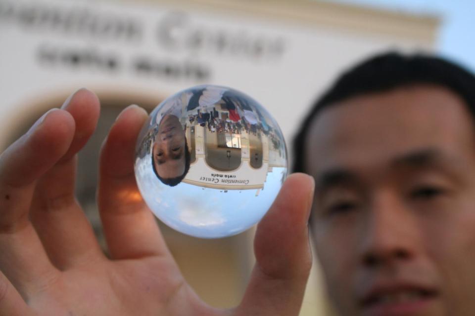
7 Non-Central Dioptric Camera Looking through a refractive glass sphere Google Crystal Ball Photography Refractive Sphere Perspective Camera
 approximation Yu and McMillan, ECCV 2004 Fast processing Similar computational complexity as perspective")
8 Goal Exact modeling of non-central cameras Rotationally Symmetric Conic Mirrors & Refractive Sphere Axial configuration: Camera placed on the axis Avoid approximations in modeling Central Approximation General linear cameras (GLC) approximation Yu and McMillan, ECCV 2004 Fast processing Similar computational complexity as perspective camera
9 Why are non-central cameras difficult to model? Following two operations are essential for any camera Back Projection What is the 3D ray corresponding to a pixel? Generic Camera Calibration Grossberg and Nayar, ICCV 2001 Sturm & Ramalingam, ECCV 2004 Ramalingam et al. CVPR 2005 Forward Projection What is the projection of a 3D point? Inverse Ray Tracing camera Compute the Light-Path pixel p 3D point P
10 Forward Projection: Easy for Perspective Camera P = [X,Y,Z] x,y x = f*x/z y = f*y/z COP Imaging Plane
11 Easy for Central Catadioptric Camera Pinhole Pixel p P = [X,Y,Z] Mirror Intersection Point Effective COP
12 But, difficult for Non-Central Camera No effective COP Pinhole Pixel p P = [X,Y,Z] How to find the Mirror Intersection Point?
13 Forward Projection for Non-Central Camera Given a 3D point P What is the corresponding image pixel p? Difficult, no closed form solution Can do optimization (Micusik and Pajdla, CVPR 2004) Iterative Forward Projection Slow Can we obtain analytical solution for forward projection for non-central cameras?
14 Analytical Forward Projection for Non-Central Cameras Axial Configuration Camera lies on the axis of rotationally symmetric mirror For conic mirrors Solve 6 th degree equation in one unknown Reduces to 4 th degree equation for spherical mirror Closed Form Solution For refractive sphere Solve 10 th degree equation in one unknown 100 times speed up 3D reconstruction using bundle adjustment
15 Finding the Mirror Intersection Point Mirror Equation
16 [x,y] lies on the mirror Constraints Mirror Equation
17 Constraints Planarity Incoming ray (v i ), normal (n) and reflected ray (v r ) lie on same plane Angle constraint θ 1 = θ 2 Use vector form of law of reflection θ 1 θ 2
18 Constraint The reflected ray should pass through the given point Cross(v r, p m) = 0
19 Solution Mirror Equation
20 Solution 6 th degree equation in y 6 solutions Get the correct solution by checking law of reflection Obtain x using 20 lines of Matlab Code
21 Mirror Shape Degree of Forward Projection Equation for Various Configurations
22 25 20 Normal COP P 5 Mirror Intersection Point Visualization for Spherical Mirror
23 COP 15 P Normal 10 5 Mirror Axis 0 Mirror Intersection Point Visualization for Hyperbolic Mirror
24 Forward Projection for Spherical Mirror Also known as Alhazen problem or Circular Billiard Problem One of the classical problem in geometry Can be traced back to Ptolemy Optics (AD 150) Described in Book of Optics (~1000 A.D) by Alhazen References Marcus Baker, Alhazen problem, American Journal of Mathematics, Vol. 4, No. 1, 1881, pp Heinrich Dorrie, 100 Great Problems of Elementary Mathematics Four solutions Intersection of circle and hyperbola Forward projection for general mirrors Extension of Alhazen problem
25 Related Work Optimization for Forward Projection Micusik and Pajdla, CVPR 2004 Iterative Forward Projection (IFP) Local perturbation method Chen and Arvo, SIGGRAPH 2000 Approximation for fast rendering GLC Approximation Ding et al. ICCV 2009 Bertrand Vandeportaele Thesis, 2006 (in French) Analysis in 3D Higher degree (8 th degree) equation for ellipsoid
26 Results: Fast Projection of 3D Points Project randomly generated 100,000 points (spherical mirror) Matlab on standard PC 1120 seconds for IFP 13.8 seconds for AFP Speed up ~80 Similar speed up for hyperbolic, elliptical and parabolic mirrors
27 Sparse 3D Reconstruction: Simulation Single perspective camera looking at 4 spherical mirrors Perturb sphere centers and add image noise Bundle Adjustment of sphere centers and 3D points

28 Sparse 3D Reconstruction: PovRay Simulation Feature extraction using SIFT Iterate bundle adjustment and outlier removal

29 Sparse 3D Reconstruction: Real Data Stainless Steel Balls
30 Epipolar Curves (Spherical Mirror) Perspective Cameras Epipolar geometry Epipolar lines Central Catadioptric Cameras Epipolar curves (2 nd order) Svoboda & Pajdla, IJCV 2002 Non-central Catadioptric Camera (Spherical Mirror) Projection of a line == 4 th order curve (Quartic curves) Derivation similar to Strum & Barreto, ECCV 2008 Back-projection matrix using lifted image coordinates
31 Forward Projection for Refractive Sphere Refractive index μ Key idea 1: Analysis can be done in a plane
32 Key idea 2 v i θ 1 n Snells Law: μ 1 sin(θ 1 ) = μ 2 sin(θ 2 ) Medium 1 Medium 2 θ 2 v r Use vector form of the refraction equation
33 Solution
34 Solution 10 th degree equation in y
35 Visualizing Solutions Radius r=1 Refractive Index μ = 1.5 D = 5 (distance of camera from refractive sphere) 8 real solutions Removing invalid refraction points Checking Snell s Law
36 3D Reconstruction using Refractive Sphere Single camera looking through 4 refractive spheres Perturb sphere centers and add image noise Jointly optimize sphere centers and 3D points

37 Summary Analytical Forward Projection Axial Non-Central Catadioptric cameras Hyperbolic, Elliptical, Spherical and Parabolic Mirrors Refractive Sphere Poor man s fish-eye lens Avoid central and GLC approximation Can use exact non-central model 100 times speed up over iterative approach Sparse 3D reconstruction using bundle adjustment Epipolar curves Quartic curves for Spherical Mirror
38 Acknowledgments Peter Sturm, INRIA MERL Jay Thornton, Keisuke Kojima, John Barnwell Mitsubishi Electric, Japan Haruhisa Okuda, Kazuhiko Sumi


39 Analytical Forward Projection for Non-Central Cameras Axial Catadioptric Camera Solve 6 th degree Equation Refractive Sphere Solve 10 th degree Equation
Relating Vanishing Points to Catadioptric Camera Calibration
 Relating Vanishing Points to Catadioptric Camera Calibration Wenting Duan* a, Hui Zhang b, Nigel M. Allinson a a Laboratory of Vision Engineering, University of Lincoln, Brayford Pool, Lincoln, U.K. LN6
Using Many Cameras as One
 Using Many Cameras as One Robert Pless Department of Computer Science and Engineering Washington University in St. Louis, Box 1045, One Brookings Ave, St. Louis, MO, 63130 pless@cs.wustl.edu Abstract We
42 CHAPTER 1. VECTORS AND THE GEOMETRY OF SPACE. Figure 1.18: Parabola y = 2x 2. 1.6.1 Brief review of Conic Sections
 2 CHAPTER 1. VECTORS AND THE GEOMETRY OF SPACE Figure 1.18: Parabola y = 2 1.6 Quadric Surfaces 1.6.1 Brief review of Conic Sections You may need to review conic sections for this to make more sense. You
Geometric Optics Converging Lenses and Mirrors Physics Lab IV
 Objective Geometric Optics Converging Lenses and Mirrors Physics Lab IV In this set of lab exercises, the basic properties geometric optics concerning converging lenses and mirrors will be explored. The
Reflection and Refraction
 Equipment Reflection and Refraction Acrylic block set, plane-concave-convex universal mirror, cork board, cork board stand, pins, flashlight, protractor, ruler, mirror worksheet, rectangular block worksheet,
Convex Mirrors. Ray Diagram for Convex Mirror
 Convex Mirrors Center of curvature and focal point both located behind mirror The image for a convex mirror is always virtual and upright compared to the object A convex mirror will reflect a set of parallel
We can display an object on a monitor screen in three different computer-model forms: Wireframe model Surface Model Solid model
 CHAPTER 4 CURVES 4.1 Introduction In order to understand the significance of curves, we should look into the types of model representations that are used in geometric modeling. Curves play a very significant
PHOTOGRAMMETRIC TECHNIQUES FOR MEASUREMENTS IN WOODWORKING INDUSTRY
 PHOTOGRAMMETRIC TECHNIQUES FOR MEASUREMENTS IN WOODWORKING INDUSTRY V. Knyaz a, *, Yu. Visilter, S. Zheltov a State Research Institute for Aviation System (GosNIIAS), 7, Victorenko str., Moscow, Russia
Aspherical Lens Design by Using a Numerical Analysis
 Journal of the Korean Physical Society, Vol. 51, No. 1, July 27, pp. 93 13 Aspherical Lens Design by Using a Numerical Analysis Gyeong-Il Kweon Department of Optoelectronics, Honam University, Gwangju
Epipolar Geometry. Readings: See Sections 10.1 and 15.6 of Forsyth and Ponce. Right Image. Left Image. e(p ) Epipolar Lines. e(q ) q R.
 Epipolar Lines. e(q ) q R.") Epipolar Geometry We consider two perspective images of a scene as taken from a stereo pair of cameras (or equivalently, assume the scene is rigid and imaged with a single camera from two different locations).
Epipolar Geometry We consider two perspective images of a scene as taken from a stereo pair of cameras (or equivalently, assume the scene is rigid and imaged with a single camera from two different locations).
Lecture 2: Homogeneous Coordinates, Lines and Conics
 Lecture 2: Homogeneous Coordinates, Lines and Conics 1 Homogeneous Coordinates In Lecture 1 we derived the camera equations λx = P X, (1) where x = (x 1, x 2, 1), X = (X 1, X 2, X 3, 1) and P is a 3 4
An introduction to Global Illumination. Tomas Akenine-Möller Department of Computer Engineering Chalmers University of Technology
 An introduction to Global Illumination Tomas Akenine-Möller Department of Computer Engineering Chalmers University of Technology Isn t ray tracing enough? Effects to note in Global Illumination image:
Determine whether the following lines intersect, are parallel, or skew. L 1 : x = 6t y = 1 + 9t z = 3t. x = 1 + 2s y = 4 3s z = s
 Homework Solutions 5/20 10.5.17 Determine whether the following lines intersect, are parallel, or skew. L 1 : L 2 : x = 6t y = 1 + 9t z = 3t x = 1 + 2s y = 4 3s z = s A vector parallel to L 1 is 6, 9,
1 of 9 2/9/2010 3:38 PM
 1 of 9 2/9/2010 3:38 PM Chapter 23 Homework Due: 8:00am on Monday, February 8, 2010 Note: To understand how points are awarded, read your instructor's Grading Policy. [Return to Standard Assignment View]
ENGN 2502 3D Photography / Winter 2012 / SYLLABUS http://mesh.brown.edu/3dp/
 ENGN 2502 3D Photography / Winter 2012 / SYLLABUS http://mesh.brown.edu/3dp/ Description of the proposed course Over the last decade digital photography has entered the mainstream with inexpensive, miniaturized
Camera geometry and image alignment
 Computer Vision and Machine Learning Winter School ENS Lyon 2010 Camera geometry and image alignment Josef Sivic http://www.di.ens.fr/~josef INRIA, WILLOW, ENS/INRIA/CNRS UMR 8548 Laboratoire d Informatique,
Name Class. Date Section. Test Form A Chapter 11. Chapter 11 Test Bank 155
 Chapter Test Bank 55 Test Form A Chapter Name Class Date Section. Find a unit vector in the direction of v if v is the vector from P,, 3 to Q,, 0. (a) 3i 3j 3k (b) i j k 3 i 3 j 3 k 3 i 3 j 3 k. Calculate
INVERSION AND PROBLEM OF TANGENT SPHERES
 South Bohemia Mathematical Letters Volume 18, (2010), No. 1, 55-62. INVERSION AND PROBLEM OF TANGENT SPHERES Abstract. The locus of centers of circles tangent to two given circles in plane is known to
Interactive 3D Scanning Without Tracking
 Interactive 3D Scanning Without Tracking Matthew J. Leotta, Austin Vandergon, Gabriel Taubin Brown University Division of Engineering Providence, RI 02912, USA {matthew leotta, aev, taubin}@brown.edu Abstract
Procedure: Geometrical Optics. Theory Refer to your Lab Manual, pages 291 294. Equipment Needed
 Theory Refer to your Lab Manual, pages 291 294. Geometrical Optics Equipment Needed Light Source Ray Table and Base Three-surface Mirror Convex Lens Ruler Optics Bench Cylindrical Lens Concave Lens Rhombus
DOING PHYSICS WITH MATLAB COMPUTATIONAL OPTICS RAYLEIGH-SOMMERFELD DIFFRACTION INTEGRAL OF THE FIRST KIND
 DOING PHYSICS WITH MATLAB COMPUTATIONAL OPTICS RAYLEIGH-SOMMERFELD DIFFRACTION INTEGRAL OF THE FIRST KIND THE THREE-DIMENSIONAL DISTRIBUTION OF THE RADIANT FLUX DENSITY AT THE FOCUS OF A CONVERGENCE BEAM
waves rays Consider rays of light from an object being reflected by a plane mirror (the rays are diverging): mirror object
: mirror object") PHYS1000 Optics 1 Optics Light and its interaction with lenses and mirrors. We assume that we can ignore the wave properties of light. waves rays We represent the light as rays, and ignore diffraction.
PHYS1000 Optics 1 Optics Light and its interaction with lenses and mirrors. We assume that we can ignore the wave properties of light. waves rays We represent the light as rays, and ignore diffraction.
IMAGE ACQUISITION CONSTRAINTS FOR PANORAMIC FRAME CAMERA IMAGING
 IMAGE ACQUISITION CONSTRAINTS FOR PANORAMIC FRAME CAMERA IMAGING H. Kauhanen a, *, P. Rönnholm a a Aalto University School of Engineering, Department of Surveying and Planning, Finland (heikki.kauhanen,
Computational Optical Imaging - Optique Numerique. -- Deconvolution --
 Computational Optical Imaging - Optique Numerique -- Deconvolution -- Winter 2014 Ivo Ihrke Deconvolution Ivo Ihrke Outline Deconvolution Theory example 1D deconvolution Fourier method Algebraic method
INTRODUCTION TO RENDERING TECHNIQUES
 INTRODUCTION TO RENDERING TECHNIQUES 22 Mar. 212 Yanir Kleiman What is 3D Graphics? Why 3D? Draw one frame at a time Model only once X 24 frames per second Color / texture only once 15, frames for a feature
Lecture Notes for Chapter 34: Images
 Lecture Notes for hapter 4: Images Disclaimer: These notes are not meant to replace the textbook. Please report any inaccuracies to the professor.. Spherical Reflecting Surfaces Bad News: This subject
Size Of the Image Nature Of the Image At Infinity At the Focus Highly Diminished, Point Real and Inverted
 CHAPTER-10 LIGHT REFLECTION AND REFRACTION Light rays; are; electromagnetic in nature, and do not need material medium for Propagation Speed of light in vacuum in 3*10 8 m/s When a light ray falls on a
8.9 Intersection of Lines and Conics
 8.9 Intersection of Lines and Conics The centre circle of a hockey rink has a radius of 4.5 m. A diameter of the centre circle lies on the centre red line. centre (red) line centre circle INVESTIGATE &
The Geometry of Perspective Projection
 The Geometry o Perspective Projection Pinhole camera and perspective projection - This is the simplest imaging device which, however, captures accurately the geometry o perspective projection. -Rays o
ANALYTICAL ANALYSIS OF BLOOD SPATTER TRAJECTORY FOR CRIME SCENE INVESTIGATION
 ANALYTICAL ANALYSIS OF BLOOD SPATTER TRAJECTORY FOR CRIME SCENE INVESTIGATION 1 NUSRAT JAHAN SHOUMY, 2 SHAHRUL NIZAM YAAKOB, 3 PHAKLEN EHKAN 1, 2, 3 School of Computer and Communication Engineering, Universiti
Chapter 23. The Reflection of Light: Mirrors
 Chapter 23 The Reflection of Light: Mirrors Wave Fronts and Rays Defining wave fronts and rays. Consider a sound wave since it is easier to visualize. Shown is a hemispherical view of a sound wave emitted
Introduction Epipolar Geometry Calibration Methods Further Readings. Stereo Camera Calibration
 Stereo Camera Calibration Stereo Camera Calibration Stereo Camera Calibration Stereo Camera Calibration 12.10.2004 Overview Introduction Summary / Motivation Depth Perception Ambiguity of Correspondence
From 3D to 2D: Orthographic and Perspective Projection Part 1
 From 3D to 2D: Orthographic and Perspective Projection Part 1 History Geometrical Constructions Types of Projection Projection in Computer Graphics Andries van Dam September 13, 2001 3D Viewing I 1/34
Joao Pedro Barreto. Dept. of Electrical and Computer Engineering R: Antonio Jose de Almeida, 295, 1Esq. University of Coimbra telf: +351 938469263
 Joao Pedro Barreto jpbar@deec.uc.pt www.deec.uc.pt/ jpbar Dept. of Electrical and Computer Engineering R: Antonio Jose de Almeida, 295, 1Esq Faculty of Science and Technology 3000-045 Coimbra, Portugal
Designing and Drawing a Sprocket Visualizing ideas through the creation of CAD solid models is a key engineering skill.
 05 Webster St. Hanover Massachusetts 0339 Tel. 78 878 5 Fax 78 878 6708 Designing and Drawing a Sprocket Visualizing ideas through the creation of CAD solid models is a key engineering skill. The following
Lecture 12: Cameras and Geometry. CAP 5415 Fall 2010
 Lecture 12: Cameras and Geometry CAP 5415 Fall 2010 The midterm What does the response of a derivative filter tell me about whether there is an edge or not? Things aren't working Did you look at the filters?
Section 12.6: Directional Derivatives and the Gradient Vector
 Section 26: Directional Derivatives and the Gradient Vector Recall that if f is a differentiable function of x and y and z = f(x, y), then the partial derivatives f x (x, y) and f y (x, y) give the rate
ME 111: Engineering Drawing
 ME 111: Engineering Drawing Lecture 4 08-08-2011 Engineering Curves and Theory of Projection Indian Institute of Technology Guwahati Guwahati 781039 Eccentrici ty = Distance of the point from the focus
Intersection of a Line and a Convex. Hull of Points Cloud
 Applied Mathematical Sciences, Vol. 7, 213, no. 13, 5139-5149 HIKARI Ltd, www.m-hikari.com http://dx.doi.org/1.12988/ams.213.37372 Intersection of a Line and a Convex Hull of Points Cloud R. P. Koptelov
Essential Mathematics for Computer Graphics fast
 John Vince Essential Mathematics for Computer Graphics fast Springer Contents 1. MATHEMATICS 1 Is mathematics difficult? 3 Who should read this book? 4 Aims and objectives of this book 4 Assumptions made
Double Tangent Circles and Focal Properties of Sphero-Conics
 Journal for Geometry and Graphics Volume 12 (2008), No. 2, 161 169. Double Tangent Circles and Focal Properties of Sphero-Conics Hans-Peter Schröcker Unit Geometry and CAD, University Innsbruck Technikerstraße
TEXTURE AND BUMP MAPPING
 Department of Applied Mathematics and Computational Sciences University of Cantabria UC-CAGD Group COMPUTER-AIDED GEOMETRIC DESIGN AND COMPUTER GRAPHICS: TEXTURE AND BUMP MAPPING Andrés Iglesias e-mail:
C) D) As object AB is moved from its present position toward the left, the size of the image produced A) decreases B) increases C) remains the same
 D) As object AB is moved from its present position toward the left, the size of the image produced A) decreases B) increases C) remains the same") 1. For a plane mirror, compared to the object distance, the image distance is always A) less B) greater C) the same 2. Which graph best represents the relationship between image distance (di) and object
1. For a plane mirror, compared to the object distance, the image distance is always A) less B) greater C) the same 2. Which graph best represents the relationship between image distance (di) and object
SolidWorks Implementation Guides. Sketching Concepts
 SolidWorks Implementation Guides Sketching Concepts Sketching in SolidWorks is the basis for creating features. Features are the basis for creating parts, which can be put together into assemblies. Sketch
Geometric Camera Parameters
 Geometric Camera Parameters What assumptions have we made so far? -All equations we have derived for far are written in the camera reference frames. -These equations are valid only when: () all distances
Anamorphic imaging with three mirrors: a survey
 Anamorphic imaging with three mirrors: a survey Joseph M. Howard Optics Branch (Code 551), NASA Goddard Space Flight Center, Greenbelt, MD 20771 Ph: 301-286-0690 Fax: 301-286-0204 Joseph.M.Howard@nasa.gov
RAY OPTICS II 7.1 INTRODUCTION
 7 RAY OPTICS II 7.1 INTRODUCTION This chapter presents a discussion of more complicated issues in ray optics that builds on and extends the ideas presented in the last chapter (which you must read first!)
12.5 Equations of Lines and Planes
 Instructor: Longfei Li Math 43 Lecture Notes.5 Equations of Lines and Planes What do we need to determine a line? D: a point on the line: P 0 (x 0, y 0 ) direction (slope): k 3D: a point on the line: P
1051-232 Imaging Systems Laboratory II. Laboratory 4: Basic Lens Design in OSLO April 2 & 4, 2002
 05-232 Imaging Systems Laboratory II Laboratory 4: Basic Lens Design in OSLO April 2 & 4, 2002 Abstract: For designing the optics of an imaging system, one of the main types of tools used today is optical
A Generic Camera Model and Calibration Method for Conventional, Wide-Angle, and Fish-Eye Lenses
 1 A Generic Camera Model and Calibration Method for Conventional, Wide-Angle, and Fish-Eye Lenses Juho Kannala and Sami S. Brandt Abstract Fish-eye lenses are convenient in such applications where a very
Metric Measurements on a Plane from a Single Image
 TR26-579, Dartmouth College, Computer Science Metric Measurements on a Plane from a Single Image Micah K. Johnson and Hany Farid Department of Computer Science Dartmouth College Hanover NH 3755 Abstract
MEASUREMENT OF END FACE GEOMETRY ON FIBER OPTIC TERMINI...2
 MEASUREMENT OF END FACE GEOMETRY ON FIBER OPTIC TERMINI...2 IMPORTANCE OF END FACE GEOMETRY...2 FIBER OPTIC CONNECTOR END FACE GEOMETRY MEASUREMENT TECHNIQUES...2 INTERFEROMETRIC MICROSCOPE TYPES...3 MEASUREMENT
Tracking in flussi video 3D. Ing. Samuele Salti
 Seminari XXIII ciclo Tracking in flussi video 3D Ing. Tutors: Prof. Tullio Salmon Cinotti Prof. Luigi Di Stefano The Tracking problem Detection Object model, Track initiation, Track termination, Tracking
3D Model based Object Class Detection in An Arbitrary View
 3D Model based Object Class Detection in An Arbitrary View Pingkun Yan, Saad M. Khan, Mubarak Shah School of Electrical Engineering and Computer Science University of Central Florida http://www.eecs.ucf.edu/
Algebra 1 Course Title
 Algebra 1 Course Title Course- wide 1. What patterns and methods are being used? Course- wide 1. Students will be adept at solving and graphing linear and quadratic equations 2. Students will be adept
BEZIER CURVES AND SURFACES
 Department of Applied Mathematics and Computational Sciences University of Cantabria UC-CAGD Group COMPUTER-AIDED GEOMETRIC DESIGN AND COMPUTER GRAPHICS: BEZIER CURVES AND SURFACES Andrés Iglesias e-mail:
Cabri Geometry Application User Guide
 Cabri Geometry Application User Guide Preview of Geometry... 2 Learning the Basics... 3 Managing File Operations... 12 Setting Application Preferences... 14 Selecting and Moving Objects... 17 Deleting
Calculation of Source-detector Solid Angle, Using Monte Carlo Method, for Radioactive Sources with Various Geometries and Cylindrical Detector
 International Journal of Pure and Applied Physics ISSN 0973-1776 Volume 3, Number 2 (2007), pp. 201 208 Research India Publications http://www.ripublication.com/ijpap.htm Calculation of Source-detector
Curves and Surfaces. Goals. How do we draw surfaces? How do we specify a surface? How do we approximate a surface?
 Curves and Surfaces Parametric Representations Cubic Polynomial Forms Hermite Curves Bezier Curves and Surfaces [Angel 10.1-10.6] Goals How do we draw surfaces? Approximate with polygons Draw polygons
A PHOTOGRAMMETRIC APPRAOCH FOR AUTOMATIC TRAFFIC ASSESSMENT USING CONVENTIONAL CCTV CAMERA
 A PHOTOGRAMMETRIC APPRAOCH FOR AUTOMATIC TRAFFIC ASSESSMENT USING CONVENTIONAL CCTV CAMERA N. Zarrinpanjeh a, F. Dadrassjavan b, H. Fattahi c * a Islamic Azad University of Qazvin - nzarrin@qiau.ac.ir
Volumes of Revolution
 Mathematics Volumes of Revolution About this Lesson This lesson provides students with a physical method to visualize -dimensional solids and a specific procedure to sketch a solid of revolution. Students
Catadioptric Sensor for a Simultaneous Tracking of the Driver s Face and the Road Scene
 Catadioptric Sensor for a Simultaneous Tracking of the Driver s Face and the Road Scene Jean-Francois Layerle, Xavier Savatier, Jean-Yves Ertaud, El Mustapha Mouaddib To cite this version: Jean-Francois
Optical Systems Design with Zemax OpticStudio. Lecture 1
 Optical Systems Design with Zemax OpticStudio Lecture 1 Why Optical Systems Design Optical system design is no longer a skill reserved for a few professionals. With readily available commercial optical
Algebra 2 Chapter 1 Vocabulary. identity - A statement that equates two equivalent expressions.
 Chapter 1 Vocabulary identity - A statement that equates two equivalent expressions. verbal model- A word equation that represents a real-life problem. algebraic expression - An expression with variables.
Section 2.4: Equations of Lines and Planes
 Section.4: Equations of Lines and Planes An equation of three variable F (x, y, z) 0 is called an equation of a surface S if For instance, (x 1, y 1, z 1 ) S if and only if F (x 1, y 1, z 1 ) 0. x + y
3 Image-Based Photo Hulls. 2 Image-Based Visual Hulls. 3.1 Approach. 3.2 Photo-Consistency. Figure 1. View-dependent geometry.
 Image-Based Photo Hulls Greg Slabaugh, Ron Schafer Georgia Institute of Technology Center for Signal and Image Processing Atlanta, GA 30332 {slabaugh, rws}@ece.gatech.edu Mat Hans Hewlett-Packard Laboratories
Specular reflection. Dielectrics and Distribution in Ray Tracing. Snell s Law. Ray tracing dielectrics
 Specular reflection Dielectrics and Distribution in Ray Tracing CS 465 Lecture 22 Smooth surfaces of pure materials have ideal specular reflection (said this before) Metals (conductors) and dielectrics
Wii Remote Calibration Using the Sensor Bar
 Wii Remote Calibration Using the Sensor Bar Alparslan Yildiz Abdullah Akay Yusuf Sinan Akgul GIT Vision Lab - http://vision.gyte.edu.tr Gebze Institute of Technology Kocaeli, Turkey {yildiz, akay, akgul}@bilmuh.gyte.edu.tr
New York State Student Learning Objective: Regents Geometry
 New York State Student Learning Objective: Regents Geometry All SLOs MUST include the following basic components: Population These are the students assigned to the course section(s) in this SLO all students
(a) We have x = 3 + 2t, y = 2 t, z = 6 so solving for t we get the symmetric equations. x 3 2. = 2 y, z = 6. t 2 2t + 1 = 0,
 We have x = 3 + 2t, y = 2 t, z = 6 so solving for t we get the symmetric equations. x 3 2. = 2 y, z = 6. t 2 2t + 1 = 0,") Name: Solutions to Practice Final. Consider the line r(t) = 3 + t, t, 6. (a) Find symmetric equations for this line. (b) Find the point where the first line r(t) intersects the surface z = x + y. (a) We
Name: Solutions to Practice Final. Consider the line r(t) = 3 + t, t, 6. (a) Find symmetric equations for this line. (b) Find the point where the first line r(t) intersects the surface z = x + y. (a) We
Arrangements And Duality
 Arrangements And Duality 3.1 Introduction 3 Point configurations are tbe most basic structure we study in computational geometry. But what about configurations of more complicated shapes? For example,
Astromechanics Two-Body Problem (Cont)
") 5. Orbit Characteristics Astromechanics Two-Body Problem (Cont) We have shown that the in the two-body problem, the orbit of the satellite about the primary (or vice-versa) is a conic section, with the
5. Orbit Characteristics Astromechanics Two-Body Problem (Cont) We have shown that the in the two-body problem, the orbit of the satellite about the primary (or vice-versa) is a conic section, with the
1. You stand two feet away from a plane mirror. How far is it from you to your image? a. 2.0 ft c. 4.0 ft b. 3.0 ft d. 5.0 ft
 Lenses and Mirrors 1. You stand two feet away from a plane mirror. How far is it from you to your image? a. 2.0 ft c. 4.0 ft b. 3.0 ft d. 5.0 ft 2. Which of the following best describes the image from
Announcements. Active stereo with structured light. Project structured light patterns onto the object
 Announcements Active stereo with structured light Project 3 extension: Wednesday at noon Final project proposal extension: Friday at noon > consult with Steve, Rick, and/or Ian now! Project 2 artifact
Cissoid. History. From Robert C. Yates Curves and their properties (1952):
:") History Cissoid Diocles ( 250 100 BC) invented this curve to solve the doubling of the cube problem (also know as the the Delian problem). The name cissoid (ivy-shaped) derives from the shape of the curve.
History Cissoid Diocles ( 250 100 BC) invented this curve to solve the doubling of the cube problem (also know as the the Delian problem). The name cissoid (ivy-shaped) derives from the shape of the curve.
Visualization and Feature Extraction, FLOW Spring School 2016 Prof. Dr. Tino Weinkauf. Flow Visualization. Image-Based Methods (integration-based)
") Visualization and Feature Extraction, FLOW Spring School 2016 Prof. Dr. Tino Weinkauf Flow Visualization Image-Based Methods (integration-based) Spot Noise (Jarke van Wijk, Siggraph 1991) Flow Visualization:
Visualization and Feature Extraction, FLOW Spring School 2016 Prof. Dr. Tino Weinkauf Flow Visualization Image-Based Methods (integration-based) Spot Noise (Jarke van Wijk, Siggraph 1991) Flow Visualization:
Refraction of Light at a Plane Surface. Object: To study the refraction of light from water into air, at a plane surface.
 Refraction of Light at a Plane Surface Object: To study the refraction of light from water into air, at a plane surface. Apparatus: Refraction tank, 6.3 V power supply. Theory: The travel of light waves
Projection Center Calibration for a Co-located Projector Camera System
 Projection Center Calibration for a Co-located Camera System Toshiyuki Amano Department of Computer and Communication Science Faculty of Systems Engineering, Wakayama University Sakaedani 930, Wakayama,
LIGHT REFLECTION AND REFRACTION
 QUESTION BANK IN SCIENCE CLASS-X (TERM-II) 10 LIGHT REFLECTION AND REFRACTION CONCEPTS To revise the laws of reflection at plane surface and the characteristics of image formed as well as the uses of reflection
Numerical Methods for Differential Equations
 Numerical Methods for Differential Equations Course objectives and preliminaries Gustaf Söderlind and Carmen Arévalo Numerical Analysis, Lund University Textbooks: A First Course in the Numerical Analysis
Feature Tracking and Optical Flow
 02/09/12 Feature Tracking and Optical Flow Computer Vision CS 543 / ECE 549 University of Illinois Derek Hoiem Many slides adapted from Lana Lazebnik, Silvio Saverse, who in turn adapted slides from Steve
Metrics on SO(3) and Inverse Kinematics
 and Inverse Kinematics") Mathematical Foundations of Computer Graphics and Vision Metrics on SO(3) and Inverse Kinematics Luca Ballan Institute of Visual Computing Optimization on Manifolds Descent approach d is a ascent direction
Mathematical Foundations of Computer Graphics and Vision Metrics on SO(3) and Inverse Kinematics Luca Ballan Institute of Visual Computing Optimization on Manifolds Descent approach d is a ascent direction
Image Formation. 7-year old s question. Reference. Lecture Overview. It receives light from all directions. Pinhole
 Image Formation Reerence http://en.wikipedia.org/wiki/lens_(optics) Reading: Chapter 1, Forsyth & Ponce Optional: Section 2.1, 2.3, Horn. The slides use illustrations rom these books Some o the ollowing
( 1)2 + 2 2 + 2 2 = 9 = 3 We would like to make the length 6. The only vectors in the same direction as v are those
2 + 2 2 + 2 2 = 9 = 3 We would like to make the length 6. The only vectors in the same direction as v are those") 1.(6pts) Which of the following vectors has the same direction as v 1,, but has length 6? (a), 4, 4 (b),, (c) 4,, 4 (d), 4, 4 (e) 0, 6, 0 The length of v is given by ( 1) + + 9 3 We would like to make
1.(6pts) Which of the following vectors has the same direction as v 1,, but has length 6? (a), 4, 4 (b),, (c) 4,, 4 (d), 4, 4 (e) 0, 6, 0 The length of v is given by ( 1) + + 9 3 We would like to make
2.1 Three Dimensional Curves and Surfaces
 . Three Dimensional Curves and Surfaces.. Parametric Equation of a Line An line in two- or three-dimensional space can be uniquel specified b a point on the line and a vector parallel to the line. The
Understanding astigmatism Spring 2003
 MAS450/854 Understanding astigmatism Spring 2003 March 9th 2003 Introduction Spherical lens with no astigmatism Crossed cylindrical lenses with astigmatism Horizontal focus Vertical focus Plane of sharpest
Dhiren Bhatia Carnegie Mellon University
 Dhiren Bhatia Carnegie Mellon University University Course Evaluations available online Please Fill! December 4 : In-class final exam Held during class time All students expected to give final this date
Lecture 17. Image formation Ray tracing Calculation. Lenses Convex Concave. Mirrors Convex Concave. Optical instruments
 Lecture 17. Image formation Ray tracing Calculation Lenses Convex Concave Mirrors Convex Concave Optical instruments Image formation Laws of refraction and reflection can be used to explain how lenses
Introduction to Computer Graphics. Reading: Angel ch.1 or Hill Ch1.
 Introduction to Computer Graphics Reading: Angel ch.1 or Hill Ch1. What is Computer Graphics? Synthesis of images User Computer Image Applications 2D Display Text User Interfaces (GUI) - web - draw/paint
CATIA Wireframe & Surfaces TABLE OF CONTENTS
 TABLE OF CONTENTS Introduction... 1 Wireframe & Surfaces... 2 Pull Down Menus... 3 Edit... 3 Insert... 4 Tools... 6 Generative Shape Design Workbench... 7 Bottom Toolbar... 9 Tools... 9 Analysis... 10
How does the Kinect work? John MacCormick
 How does the Kinect work? John MacCormick Xbox demo Laptop demo The Kinect uses structured light and machine learning Inferring body position is a two-stage process: first compute a depth map (using structured
The Wide Field Cassegrain: Exploring Solution Space
 The Wide Field Cassegrain: Exploring Solution Space Peter Ceravolo Ceravolo Optical Systems www.ceravolo.com peter@ceravolo.com Abstract This article illustrates the use of an internal aperture stop in
High-resolution Imaging System for Omnidirectional Illuminant Estimation
 High-resolution Imaging System for Omnidirectional Illuminant Estimation Shoji Tominaga*, Tsuyoshi Fukuda**, and Akira Kimachi** *Graduate School of Advanced Integration Science, Chiba University, Chiba
Chapter 17: Light and Image Formation
 Chapter 17: Light and Image Formation 1. When light enters a medium with a higher index of refraction it is A. absorbed. B. bent away from the normal. C. bent towards from the normal. D. continues in the
Physics 25 Exam 3 November 3, 2009
 1. A long, straight wire carries a current I. If the magnetic field at a distance d from the wire has magnitude B, what would be the the magnitude of the magnetic field at a distance d/3 from the wire,
Computer Graphics Global Illumination (2): Monte-Carlo Ray Tracing and Photon Mapping. Lecture 15 Taku Komura
: Monte-Carlo Ray Tracing and Photon Mapping. Lecture 15 Taku Komura") Computer Graphics Global Illumination (2): Monte-Carlo Ray Tracing and Photon Mapping Lecture 15 Taku Komura In the previous lectures We did ray tracing and radiosity Ray tracing is good to render specular
Computer Graphics Global Illumination (2): Monte-Carlo Ray Tracing and Photon Mapping Lecture 15 Taku Komura In the previous lectures We did ray tracing and radiosity Ray tracing is good to render specular
Computer Graphics. Geometric Modeling. Page 1. Copyright Gotsman, Elber, Barequet, Karni, Sheffer Computer Science - Technion. An Example.
 An Example 2 3 4 Outline Objective: Develop methods and algorithms to mathematically model shape of real world objects Categories: Wire-Frame Representation Object is represented as as a set of points
Geometry: Unit 1 Vocabulary TERM DEFINITION GEOMETRIC FIGURE. Cannot be defined by using other figures.
 Geometry: Unit 1 Vocabulary 1.1 Undefined terms Cannot be defined by using other figures. Point A specific location. It has no dimension and is represented by a dot. Line Plane A connected straight path.
Activity Set 4. Trainer Guide
 Geometry and Measurement of Solid Figures Activity Set 4 Trainer Guide Mid_SGe_04_TG Copyright by the McGraw-Hill Companies McGraw-Hill Professional Development GEOMETRY AND MEASUREMENT OF SOLID FIGURES
Optics and Geometry. with Applications to Photography Tom Davis tomrdavis@earthlink.net http://www.geometer.org/mathcircles November 15, 2004
 Optics and Geometry with Applications to Photography Tom Davis tomrdavis@earthlink.net http://www.geometer.org/mathcircles November 15, 2004 1 Useful approximations This paper can be classified as applied