λ = l f = ( m) ( Hz) λ = l f = ( m) ( Hz) λ = l f = ( m) ( Hz)
|
|
|
- Oscar Jacobs
- 7 years ago
- Views:
Transcription
1 Problem 2.1 A transmission line of length l connects a load to a sinusoidal voltage source with an oscillation frequency f. Assuming the velocity of wave propagation on the line is c, for which of the following situations is it reasonable to ignore the presence of the transmission line in the solution of the circuit: (a) l = 20 cm, f = 20 khz, (b) l = 50 km, f = 60 Hz, (c) l = 20 cm, f = 600 MHz, (d) l = 1 mm, f = 100 GHz. Solution: A transmission line is negligible when l/λ (a) l λ = l f = ( m) ( Hz) u p = (negligible). m/s (b) l λ = l f = ( m) ( Hz) u p = 0.01 (borderline). m/s (c) l λ = l f = ( m) ( Hz) u p = 0.40 (nonnegligible). m/s (d) l λ = l f = ( m) ( Hz) u p = 0.33 (nonnegligible). m/s
2 Problem 2.2 A two-wire copper transmission line is embedded in a dielectric material with ε r = 2.6 and σ = S/m. Its wires are separated by 3 cm and their radii are 1 mm each. (a) Calculate the line parameters R, L, G, and C at 2 GHz. (b) Compare your results with those based on CD Module 2.1. Include a printout of the screen display. Solution: (a) Given: From Table 2-1: f = Hz, d = m, D = m, σ c = S/m (copper), ε r = 2.6, σ = S/m, µ = µ c = µ 0. R s = π f µ c /σ c = [π π 10 7 / ] 1/2 = Ω, R = 2R s = πd 2π 10 3 = 3.71 Ω/m, L = µ ] [(D/d)+ π ln (D/d) 2 1 = H/m, G πσ = ln[(d/d)+ (D/d) 2 1] = S/m, C = G ε σ (b) Solution via Module 2.1: = = F/m.
3
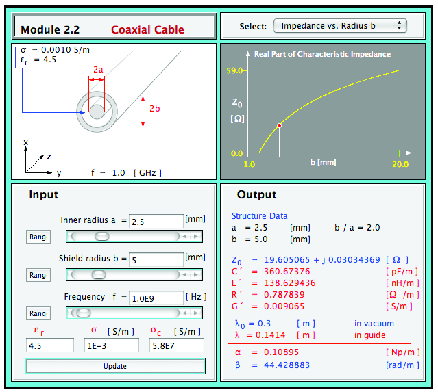
4 Problem 2.6 A coaxial line with inner and outer conductor diameters of 0.5 cm and 1 cm, respectively, is filled with an insulating material with ε r = 4.5 and σ = 10 3 S/m. The conductors are made of copper. (a) Calculate the line parameters at 1 GHz. (b) Compare your results with those based on CD Module 2.2. Include a printout of the screen display. Solution: (a) Given a = (0.5/2) cm = m, b = (1.0/2) cm = m, combining Eqs. (2.5) and (2.6) gives R = 1 ( π f µc 1 2π σ c a + 1 ) b = 1 π(10 9 Hz)(4π 10 7 H/m) 2π S/m = Ω/m. From Eq. (2.7), From Eq. (2.8), From Eq. (2.9), C = L = µ 2π ln ( b a ) ( ) m m = 4π 10 7 H/m ln2 = 139 nh/m. 2π G = 2πσ ln(b/a) = 2π 10 3 S/m = 9.1 ms/m. ln2 2πε ln(b/a) = 2πε rε 0 ln(b/a) = 2π 4.5 ( F/m) = 362 pf/m. ln2 (b) Solution via Module 2.2:
5
6 Problem 2.7 Find α, β, u p, and Z 0 for the two-wire line of Problem 2.2. Compare results with those based on CD Module 2.1. Include a printout of the screen display. Solution: From Problem 2.2: At 2 GHz: Hence R = 3.71 Ω/m, L = H/m, G = S/m, C = F/m. γ = (R + jωl )(G + jωc ) = j α = Np/m, β = rad/m. u p = ω 2π = = m/s, β R Z 0 = + jωl G = 253 Ω. + jωc
7
8 Problem 2.9 A lossless microstrip line uses a 1-mm wide conducting strip over a 1-cm thick substrate with ε r = 2.5. Determine the line parameters, ε eff, Z 0, and β at 10 GHz. Compare your results with those obtained by using CD Module 2.3. Include a printout of the screen display. Solution: Given w = 10 3 m, h = 10 2 m, ε r = 2.5, f = Hz, s = w h = 0.1. From Eq. (2.36), with ε eff = ε r ( εr )( ) xy s ] 0.05 [ εr 0.9 x = 0.56 ε r + 3 [ ] = 0.56 = 0.526, ( s s 2 ) y = ln s ln( s 3 ) 0.83, which leads to By Eq. (2.39), with Hence, ε eff { } Z 0 = 60 6+(2π 6)e t ln s εeff s 2 ( ) t = = s ( ) = Z 0 = Ω.

9 Also, β = ω c εeff = 2π = rad/m.
10 Problem 2.16 A transmission line operating at 125 MHz has Z 0 = 40 Ω, α = 0.02 (Np/m), and β = 0.75 rad/m. Find the line parameters R, L, G, and C. Solution: Given an arbitrary transmission line, f = 125 MHz, Z 0 = 40 Ω, α = 0.02 Np/m, and β = 0.75 rad/m. Since Z 0 is real and α 0, the line is distortionless. From Problem 2.13, β = ω L C and Z 0 = L /C, therefore, L = βz 0 ω = = 38.2 nh/m. 2π Then, from Z 0 = L /C, C = L Z 2 0 = From α = R G and R C = L G, 38.2 nh/m 40 2 = 23.9 pf/m. and R = R G R G = R G L C = αz 0 = 0.02 Np/m 40 Ω = 0.6 Ω/m G = α2 (0.02 Np/m)2 R = = 0.5 ms/m. 0.8 Ω/m
11 Problem 2.18 Polyethylene with ε r = 2.25 is used as the insulating material in a lossless coaxial line with characteristic impedance of 50 Ω. The radius of the inner conductor is 1.2 mm. (a) What is the radius of the outer conductor? (b) What is the phase velocity of the line? Solution: Given a lossless coaxial line, Z 0 = 50 Ω, ε r = 2.25, a = 1.2 mm: (a) From Table 2-2, Z 0 = (60/ ε r )ln(b/a) which can be rearranged to give (b) Also from Table 2-2, b = ae Z 0 εr /60 = (1.2 mm)e /60 = 4.2 mm. u p = c = m/s = m/s. εr 2.25
12 Problem 2.19 A 50-Ω lossless transmission line is terminated in a load with impedance Z L = (30 j50) Ω. The wavelength is 8 cm. Find: (a) the reflection coefficient at the load, (b) the standing-wave ratio on the line, (c) the position of the voltage maximum nearest the load, (d) the position of the current maximum nearest the load. (e) Verify quantities in parts (a) (d) using CD Module 2.4. Include a printout of the screen display. Solution: (a) From Eq. (2.59), (b) From Eq. (2.73), (c) From Eq. (2.70) Γ = Z L Z 0 (30 j50) 50 j79.8 = = 0.57e. Z L + Z 0 (30 j50)+50 S = 1+ Γ 1 Γ = = d max = θ rλ 4π + nλ 2 = cm π rad 4π n 8 cm 2 = 0.89 cm+4.0 cm = 3.11 cm. (d) A current maximum occurs at a voltage minimum, and from Eq. (2.72), d min = d max λ/4 = 3.11 cm 8 cm/4 = 1.11 cm. (e) The problem statement does not specify the frequency, so in Module 2.4 we need to select the combination of f and ε r such that λ = 5 cm. With ε r chosen as 1, f = c λ = = 3.75 GHz The generator parameters are irrelevant to the problem. The results listed in the output screens are very close to those given in parts (a) through (d).
")
13 Figure P2.19(a)
")
14 Figure P2.19(b)
15 Problem 2.21 On a 150-Ω lossless transmission line, the following observations were noted: distance of first voltage minimum from the load = 3 cm; distance of first voltage maximum from the load = 9 cm; S = 3. Find Z L. Solution: Distance between a minimum and an adjacent maximum = λ/4. Hence, 9 cm 3 cm = 6 cm = λ/4, or λ = 24 cm. Accordingly, the first voltage minimum is at d min = 3 cm = λ 8. Application of Eq. (2.71) with n = 0 gives which gives θ r = π/2. Hence, Γ = 0.5e jπ/2 = j0.5. Finally, θ r 2 2π λ λ 8 = π, Γ = S 1 S+1 = = 2 4 = 0.5. [ ] 1+Γ Z L = Z 0 = Γ [ ] 1 j0.5 = (90 j120) Ω. 1+ j0.5
16 Problem 2.24 A 50-Ω lossless line terminated in a purely resistive load has a voltage standing-wave ratio of 3. Find all possible values of Z L. Solution: Γ = S 1 S+1 = = 0.5. For a purely resistive load, θ r = 0 or π. For θ r = 0, ] = 50 Z L = Z 0 [ 1+Γ 1 Γ [ ] = 150 Ω. For θ r = π, Γ = 0.5 and Z L = 50 [ ] = 15 Ω
A wave lab inside a coaxial cable
 INSTITUTE OF PHYSICS PUBLISHING Eur. J. Phys. 25 (2004) 581 591 EUROPEAN JOURNAL OF PHYSICS PII: S0143-0807(04)76273-X A wave lab inside a coaxial cable JoãoMSerra,MiguelCBrito,JMaiaAlves and A M Vallera
PHY3128 / PHYM203 (Electronics / Instrumentation) Transmission Lines. Repeated n times I L
 Transmission Lines. Repeated n times I L") Transmission Lines Introduction A transmission line guides energy from one place to another. Optical fibres, waveguides, telephone lines and power cables are all electromagnetic transmission lines. are
Transmission Lines Introduction A transmission line guides energy from one place to another. Optical fibres, waveguides, telephone lines and power cables are all electromagnetic transmission lines. are
COAX Cables Radio Frequency Cables
 COAX Cables Radio Frequency Cables Contents Page Table of contents Pictographs General information Introduction Types and abbreviations Temparature range Construction Characteristics Special constructions
45. The peak value of an alternating current in a 1500-W device is 5.4 A. What is the rms voltage across?
 PHYS Practice Problems hapters 8- hapter 8. 45. The peak value of an alternating current in a 5-W device is 5.4 A. What is the rms voltage across? The power and current can be used to find the peak voltage,
Experiments Using the HP8714 RF Network Analyzer
 Experiments Using the HP8714 RF Network Analyzer Purpose: The purpose of this set of experiments is two folded: to get familiar with the basic operation of a RF network analyzer, and to gain a physical
DRAFT. University of Pennsylvania Moore School of Electrical Engineering ESE319 Electronic Circuits - Modeling and Measurement Techniques
 University of Pennsylvania Moore School of Electrical Engineering ESE319 Electronic Circuits - Modeling and Measurement Techniques 1. Introduction. Students are often frustrated in their attempts to execute
2/20/2009 3 Transmission Lines and Waveguides.doc 1/3. and Waveguides. Transmission Line A two conductor structure that can support a TEM wave.
 2/20/2009 3 Transmission Lines and Waveguides.doc 1/3 Chapter 3 Transmission Lines and Waveguides First, some definitions: Transmission Line A two conductor structure that can support a TEM wave. Waveguide
Commercial Coaxial Cable
 Commercial Coaxial Cable For the Best in COMMERCIAL TV Reception Solutions! Do you require a Digital TV reception system for your next project? Matchmaster can supply For The Best Design and supply of
The Quality Connection. Cable Solutions for Mobile Networks Business Unit Telecom
 The Quality Connection Cable Solutions for Mobile Networks Business Unit Telecom Connection Technology for Wireless Communication Systems A consistent focus on the market, in-depth sector and product knowledge,
Software for Design NMR Probes Using the Shielded Split Ring and the Shielded Symmetrical Band Resonators
 Software for Design NMR Probes Using the Shielded Split Ring and the Shielded Symmetrical Band Resonators Nasreddine Benahmed University of Tlemcen, Algeria ABSTRACT This article presents a software (NMR
TFC/U-JIN Coaxial Cable Product Information Sheet Type: TU6T60-JVB
 Type: TU6T60-JVB Dielectric 2nd Outer (w/optional Floodant) Series 6 Coaxial Cable Copper Clad Steel Foamed Polyethylene Dielectric Bonded AP Laminate Shield 60% Aluminum Braid "Life Time" compound AP
Module 1 : Conduction. Lecture 5 : 1D conduction example problems. 2D conduction
 Module 1 : Conduction Lecture 5 : 1D conduction example problems. 2D conduction Objectives In this class: An example of optimization for insulation thickness is solved. The 1D conduction is considered
I-PEX MHF4 Micro Coaxial Connector
 PRODUCT SPECIFICATION I-PEX MHF4 Micro Coaxial Connector Plug P/N 20448-001R-81 Receptacle P/N 20449-001E RF Connector, RF Cable & Antenna Manufacturer E-mail: sales@wellshow.com.tw Tel: +886-2-24239376
Application Note. So You Need to Measure Some Inductors?
 So You Need to Measure Some nductors? Take a look at the 1910 nductance Analyzer. Although specifically designed for production testing of inductors and coils, in addition to measuring inductance (L),
RF data receiver super-reactive ASK modulation, low cost and low consumption ideal for Microchip HCS KEELOQ decoder/encoder family. 0.
 Receiver AC-RX2/CS RF data receiver super-reactive ASK modulation, low cost and low consumption ideal for Microchip HCS KEELOQ decoder/encoder family. Pin-out 38.1 3 Component Side 1 2 3 7 11 13 14 15
PHY114 S11 Term Exam 3
 PHY4 S Term Exam S. G. Rajeev Mar 2 20 2:0 pm to :45 pm PLEASE write your workshop number and your workshop leader s name at the top of your book, so that you can collect your graded exams at the workshop.
LOW COST MOTOR PROTECTION FILTERS FOR PWM DRIVE APPLICATIONS STOPS MOTOR DAMAGE
 LOW COST MOTOR PROTECTION FILTERS FOR PWM DRIVE APPLICATIONS STOPS MOTOR DAMAGE Karl M. Hink, Executive Vice President Originally presented at the Power Quality 99 Conference ABSTRACT Motor protection
Understanding SWR by Example
 Understanding SWR by Example Take the mystery and mystique out of standing wave ratio. Darrin Walraven, K5DVW It sometimes seems that one of the most mysterious creatures in the world of Amateur Radio
Cable Analysis and Fault Detection using the Bode 100
 Cable Analysis and Fault Detection using the Bode 100 By Stephan Synkule 2014 by OMICRON Lab V1.3 Visit www.omicron-lab.com for more information. Contact support@omicron-lab.com for technical support.
Communication, Signal & Data Cables
 Communication, Signal & Data Cables Used for indoor installation and interconnection of transmission, telephone, telegraph and electronic equipment as well as media equipments www.alfanar.com Communication
MICROCABLES. A complete vision of your connectivity needs. Catalogue
 MICROCABLES A complete vision of your connectivity needs Catalogue ELECTRONIC Filotex Introduction Application Nexans s line of microcables is designed towards the increasing requirements of electronics
Oscar E. Morel UtilX Corporation
 Oscar E. Morel UtilX Corporation Time Domain Reflectometry (TDR) has been the preferred technique to assess: Cable length Splice number and spatial location, and Metallic neutral condition Tests for neutral
Cable Solutions for Servo and Variable Frequency Drives (VFD)
") Cable Solutions for Servo and Variable Frequency Drives (VFD) Electric drive systems with continuous torque and speed control are widespread today. They allow an optimal adjustment of the drive with respect
Cable Solutions for Servo and Variable Frequency Drives (VFD) Electric drive systems with continuous torque and speed control are widespread today. They allow an optimal adjustment of the drive with respect
Coaxial Cables for Medium-Frequency Applications
 Coaxial Cables for Medium-Frequency Applications Coaxial Cables for Medium-Frequency Applications Introduction Telecommunications technology is moving forward rapidly and the need for fast and reliable
RLC Resonant Circuits
 C esonant Circuits Andrew McHutchon April 20, 203 Capacitors and Inductors There is a lot of inconsistency when it comes to dealing with reactances of complex components. The format followed in this document
Transmission Lines in Communication Systems FACET
 Computer-Based Electronics Training System Transmission Lines in Communication Systems FACET 36970- Order no.: 36970-00 First Edition Revision level: 02/2015 By the staff of Festo Didactic Festo Didactic
Determining wave propagation characteristics of MV XLPE power cable using time domain reflectometry technique
 Turk J Elec Eng & Comp Sci, Vol.19, No.2, 2011, c TÜBİTAK doi:10.3906/elk-1001-371 Determining wave propagation characteristics of MV XLPE power cable using time domain reflectometry technique Ghulam Murtaza
Trunk Cables. www.teletronik.com
 Trunk Cables www.teletronik.com Brief Introduction Teletronik TC series coaxial cable was developed to meet the increasing demand of tomorrow's broadband networks. TC series cable has the highest reliability
Transmission Line Transformers
 Radio Frequency Circuit Design. W. Alan Davis, Krishna Agarwal Copyright 2001 John Wiley & Sons, Inc. Print ISBN 0-471-35052-4 Electronic ISBN 0-471-20068-9 CHAPTER SIX Transmission Line Transformers 6.1
WAVEGUIDE-COAXIAL LINE TRANSITIONS
 WAVEGUIDE-COAXIAL LINE TRANSITIONS 1. Overview Equipment at microwave frequencies is usually based on a combination of PCB and waveguide components. Filters and antennas often use waveguide techniques,
Digital Systems Ribbon Cables I CMPE 650. Ribbon Cables A ribbon cable is any cable having multiple conductors bound together in a flat, wide strip.
 Ribbon Cables A ribbon cable is any cable having multiple conductors bound together in a flat, wide strip. Each dielectric configuration has different high-frequency characteristics. All configurations
TECHNICAL SPECIFICATION
 TECHNICAL SPECIFICATION 4 PAIR UTP CABLE (ENHANCED CATEGORY 5) PVC (CM Grade) Page 1 of 6 1. SCOPE This specification is based on the specifications of UL 444, ANSI/TIA/EIA-568-B.2, UL 1685 and covers
EECC694 - Shaaban. Transmission Channel
 The Physical Layer: Data Transmission Basics Encode data as energy at the data (information) source and transmit the encoded energy using transmitter hardware: Possible Energy Forms: Electrical, light,
Transmission Lines. Smith Chart
 Smith Chart The Smith chart is one of the most useful graphical tools for high frequency circuit applications. The chart provides a clever way to visualize complex functions and it continues to endure
Six-Port Reflectometer: an Alternative Network Analyzer for THz Region. Guoguang Wu
 Six-Port Reflectometer: an Alternative Network Analyzer for THz Region Guoguang Wu Outline General Background of Network Analyzer Principles of Six-Port Reflectometer WR-15 Six-port Reflectometer Design,
CC-Link Ver.1.10 Compatible
 Model Title CC-Link Ver.1.10 Compatible CC-Link Flexible Cable Conformance Test Specifications Management number : BAP-C0401-009 CC-Link Partner Association (1/12) Revisions Revision item Revision Description
Human Exposure to Outdoor PLC System
 1602 PIERS Proceedings, Marrakesh, MOROCCO, March 20 23, 2011 Human Exposure to Outdoor PLC System Vicko Doric 1, Dragan Poljak 1, and Khalil El Khamlichi Drissi 2 1 University of Split, Croatia 2 Blaise
Investigation of the Residual-charge Technique for Diagnosis of Water-tree Deteriorated Cross-linked Polyethylene Cable
 Investigation of the Residual-charge Technique for Diagnosis of Water-tree Deteriorated Cross-linked Polyethylene Cable Dr. Uchida Katsumi*, Youichi Katou*, Dr. Hiroyuki Kon, Dr. Kazuo Watanabe and Takenori
coaxial cable coaxial Cable CERTIFIED 100% certified coaxial cable A cable that is marked Televés, no doubt is a certified cable
 COAXIAL CABLE coaxial Cable 100% certified coaxial cable coaxial cable CERTIFIED The step ahead undertaken by Televés to improve its service and technical excellence, is now reflected in this new challenge.
WHITEPAPER. Cable and Connector for Hiperface dsl motor drive applications
 WHITEPAPER Cable and Connector for Hiperface dsl motor drive applications information for cable manufacturers Version 02 Content Information for cable manufacturers...3 Communication...3 Crosstalk & shielding...3
Solution. (Chapters 5-6-7-8) Dr. Hasan Qunoo. The Islamic University of Gaza. Faculty of Engineering. Computer Engineering Department
 Dr. Hasan Qunoo. The Islamic University of Gaza. Faculty of Engineering. Computer Engineering Department") The Islamic University of Gaza Faculty of Engineering Computer Engineering Department Data Communications ECOM 4314 Solution (Chapters 5-6-7-8) Dr. Hasan Qunoo Eng. Wafaa Audah Eng. Waleed Mousa 1. A cable
The Islamic University of Gaza Faculty of Engineering Computer Engineering Department Data Communications ECOM 4314 Solution (Chapters 5-6-7-8) Dr. Hasan Qunoo Eng. Wafaa Audah Eng. Waleed Mousa 1. A cable
Semi-rigid Coaxial Cables
 50 Ohm RF Coaxial Cables Semi-rigid Coaxial Cables SR034 SR047/M17 SR086 /M17 SR086-25 SR086-75 SR090-25 SR141 SR141-25 SR141-35 SR141-75 SR250 SR250-75 147 Semi-rigid Coaxial Cabless SR034 Inner conductor
Times Microwave Systems Hermetically Sealed Assemblies
 SCOPE This Specification details the Electrical, Mechanical and Environmental Characteristics of Times Microwave Systems MILTECH 340.34 Diameter Hermetically Sealed Coaxial Transmission Lines. This product
75 Ω Transmission System
 NRAO NTC-DSL Laboratory Report Dynamic Spectroscopy Laboratory Report Series Report 03 September, 2006 75 Ω Transmission System Chaitali R. Parashare Department of Electrical and Computer Engineering,
Selecting a Transmission Line for Your Broadcast System
 Selecting a Transmission Line for Your Broadcast System Introduction This Bulletin presents the procedures broadcasters need for calculating attenuation and power handling parameters to properly design
CAVEL VS80205 MADE IN ITALY 1000 V
 0,05 9,00 x 7,20 (Pet) (LSZH) Attached CE01 CE02 Sheath Colour black black red Non-migrating Polyester tape longitudinally overlapped (Pet) 25 x 23 µm Outer sheath of Thermoplastic material - black - halogen-free,
Physics 25 Exam 3 November 3, 2009
 1. A long, straight wire carries a current I. If the magnetic field at a distance d from the wire has magnitude B, what would be the the magnitude of the magnetic field at a distance d/3 from the wire,
Single Transistor FM Transmitter Design
 Single Transistor FM Transmitter Design In telecommunications, frequency modulation (FM) conveys information over a carrier wave by varying its frequency. FM is commonly used at VHF radio frequencies for
ELECTRICAL CHARACTERISATION OF SEMI-RIGID COAXIAL CABLES WITH SMA AND K CONNECTORS. Carmen Diez Rafael García Juan Daniel Gallego.
 ELECTRICAL CHARACTERISATION OF SEMI-RIGID COAXIAL CABLES WITH SMA AND K CONNECTORS March 2005 TECHNICAL REPORT C.A.Y. 2005-4 ABSTRACT Semi-rigid coaxial transitions are normally used in closed cycle refrigerators
Engineering Sciences 151. Electromagnetic Communication Laboratory Assignment 3 Fall Term 1998-99
 Engineering Sciences 151 Electromagnetic Communication Laboratory Assignment 3 Fall Term 1998-99 WAVE PROPAGATION II: HIGH FREQUENCY SLOTTED LINE AND REFLECTOMETER MEASUREMENTS OBJECTIVES: To build greater
EVOline Multimedia Modules
 243 EVOline VGA cable EVOline DVI-A cable EVOline DVI-D cable EVOline HDMI cable Cable properties Flame retardant self extinguishing VW-1 Halogen free yes yes yes Colour Black Black Outer diameter 7,2
EARTHING SYSTEM CALCULATION
 BAZIAN STEAL FACTORY S/S 132/11kV, 1x30/40MVA EARTHING SYSTEM CALCULATION Kurdistan Region Sulaimani May 2011 Bazian Steal Factory S/S 132/11kV, 1x30/40 MVA Contents: 1. Introduction... 3 2. List of references
RX-AM4SF Receiver. Pin-out. Connections
 RX-AM4SF Receiver The super-heterodyne receiver RX-AM4SF can provide a RSSI output indicating the amplitude of the received signal: this output can be used to create a field-strength meter capable to indicate
Broadband Slotted Coaxial Broadcast Antenna Technology
 Broadband Slotted Coaxial Broadcast Antenna Technology Summary Slotted coaxial antennas have many advantages over traditional broadband panel antennas including much smaller size and wind load, higher
CHAPTER4 GENERAL ASPECTS OF MUTUAL
 CHAPTER4 GENERAL ASPECTS OF MUTUAL ADMITTANCE OF CPW-FED TWIN SLOTS ON CONDUCTOR-BACKED TWO-LAYER SUBSTRATES 4.1 INTRODUCTORY REMARKS The present chapter is concerned with an exploratory investigation
Network Standard Advice No. 1420C 9/6/2011
 Network Standard Advice No. 1420C 9/6/2011 TO: Customers, Service Providers and Ausgrid Staff. Advisory Note on Changes to the Use of 11kV Cable Types. Introduction This Network Standard Advice (NSA) provides
SICK AG WHITEPAPER. Information for cable manufacturers Note-2_03
 SICK AG WHITEPAPER Cable and connector for HIPERFACE DSL motor drive applications Information for cable manufacturers Note-2_03 Juergen Funkhaenel Application Engineer at SICK STEGMANN GmbH Donaueschingen
Current Probes. User Manual
 Current Probes User Manual ETS-Lindgren L.P. reserves the right to make changes to any product described herein in order to improve function, design, or for any other reason. Nothing contained herein shall
For a shielded cable, an approximate
 Simple Method for Predicting a Cable Shielding Factor, Based on Transfer Impedance MICHEL MARDIGUIAN EMC Consultant St. Remy les Chevreuse, France For a shielded cable, an approximate relationship valid
Features. Applications. Transmitter. Receiver. General Description MINIATURE MODULE. QM MODULATION OPTIMAL RANGE 1000m
 Features MINIATURE MODULE QM MODULATION OPTIMAL RANGE 1000m 433.05 434.79 ISM BAND 34 CHANNELS AVAILABLE SINGLE SUPPLY VOLTAGE Applications IN VEHICLE TELEMETRY SYSTEMS WIRELESS NETWORKING DOMESTIC AND
SMA Interface Mating Dimensions (Per MIL-STD-348)
") SMA Series SMA 6 SMA Interface Mating Dimensions (Per MIL-STD-348) SMA Interface Dimensions MALE Inches/Millimeters 3 Minimum Nominal Maximum LTR in. mm in. mm in. mm A.250 6.35.263 6.68.. B.1790 4.55.1808
SMA Series SMA 6 SMA Interface Mating Dimensions (Per MIL-STD-348) SMA Interface Dimensions MALE Inches/Millimeters 3 Minimum Nominal Maximum LTR in. mm in. mm in. mm A.250 6.35.263 6.68.. B.1790 4.55.1808
If you want to get an official version of this User Network Interface Specification, please order it by sending your request to:
 This specification describes the situation of the Proximus network and services. It will be subject to modifications for corrections or when the network or the services will be modified. Please take into
Shielding Effectiveness Test Method. Harbour s LL, SB, and SS Coaxial Cables. Designs for Improved Shielding Effectiveness
 Shielding Effectiveness Test Method Harbour s LL, SB, and SS Coaxial Cables Designs for Improved Shielding Effectiveness Harbour Industries 4744 Shelburne Road Shelburne Vermont 05482 USA 802-985-3311
Antenna Trainer EAN. www.edibon.com. Technical Teaching Equipment INTRODUCTION
 Antenna Trainer EAN Technical Teaching Equipment Products Products range Units 3.-Communications INTRODUCTION Antennas are the main element of aerial communications. They are the transition between a transmission
AS COMPETITION PAPER 2007 SOLUTIONS
 AS COMPETITION PAPER 2007 Total Mark/50 SOLUTIONS Section A: Multiple Choice 1. C 2. D 3. B 4. B 5. B 6. A 7. A 8. C 1 Section B: Written Answer Question 9. A mass M is attached to the end of a horizontal
Changes PN532_Breakout board
 Changes PN532_Breakout board Document: Changes PN532_Breakout board Department / Faculty : TechnoCentrum - Radboud University Nijmegen Contact: René Habraken Date: 17 May 2011 Doc. Version: 1.0 Contents
An equivalent circuit of a loop antenna.
 3.2.1. Circuit Modeling: Loop Impedance A loop antenna can be represented by a lumped circuit when its dimension is small with respect to a wavelength. In this representation, the circuit parameters (generally
Standex-Meder Electronics. Custom Engineered Solutions for Tomorrow
 Standex-Meder Electronics Custom Engineered Solutions for Tomorrow RF Reed Relays Part II Product Training Copyright 2013 Standex-Meder Electronics. All rights reserved. Introduction Purpose Designing
Connectivity in a Wireless World. Cables Connectors 2014. A Special Supplement to
 Connectivity in a Wireless World Cables Connectors 204 A Special Supplement to Signal Launch Methods for RF/Microwave PCBs John Coonrod Rogers Corp., Chandler, AZ COAX CABLE MICROSTRIP TRANSMISSION LINE
Eatman Associates 2014 Rockwall TX 800-388-4036 rev. October 1, 2014. Striplines and Microstrips (PCB Transmission Lines)
") Eatman Associates 2014 Rockwall TX 800-388-4036 rev. October 1, 2014 Striplines and Microstrips (PCB Transmission Lines) Disclaimer: This presentation is merely a compilation of information from public
Eatman Associates 2014 Rockwall TX 800-388-4036 rev. October 1, 2014 Striplines and Microstrips (PCB Transmission Lines) Disclaimer: This presentation is merely a compilation of information from public
Subject: Glenair MIL-PRF 24758 Conduit Surface Transfer Impedance Test
 Lothar O. Hoeft, Ph.D. Consultant, Electromagnetic Effects 5012 San Pedro Ct., NE Albuquerque, New Mexico 87109-2515 Phone: (505)-889-9705 E-mail: bud.hoeft@ieee.org 1 February 24, 2006 Subject: Glenair
Chapter 15: Transformer design
 Chapter 15 Transformer Design Some more advanced design issues, not considered in previous chapter: : n Inclusion of core loss + + Selection of operating flux i 1 density to optimize total loss v 1 v Multiple
1. A wire carries 15 A. You form the wire into a single-turn circular loop with magnetic field 80 µ T at the loop center. What is the loop radius?
 CHAPTER 3 SOURCES O THE MAGNETC ELD 1. A wire carries 15 A. You form the wire into a single-turn circular loop with magnetic field 8 µ T at the loop center. What is the loop radius? Equation 3-3, with
EEL303: Power Engineering I - Tutorial 4
 1. Determine the voltage at the generating station and the efficiency of the following system (Figure 1): Both transformers have ratio of 2kV/11kV. The resistance on LV side of both Figure 1: transformers
SECTION 2 Transmission Line Theory
 SEMICONDUCTOR DESIGN GUIDE Transmission Line Theory SECTION 2 Transmission Line Theory Introduction The ECLinPS family has pushed the world of ECL into the realm of picoseconds. When output transitions
Fundamentals of Electromagnetic Fields and Waves: I
 Fundamentals of Electromagnetic Fields and Waves: I Fall 2007, EE 30348, Electrical Engineering, University of Notre Dame Mid Term II: Solutions Please show your steps clearly and sketch figures wherever
FM Radio Transmitter & Receiver Modules
 FM Radio Transmitter & Receiver Modules T5 / R5 Features MINIATURE SIL PACKAGE FULLY SHIELDED DATA RATES UP TO 128KBITS/S RANGE UPTO 300 METRES SINGLE SUPPLY VOLTAGE INDUSTRY PIN COMPATIBLE QFMT5-434 TEMP
6 ELECTRICAL PARAMETERS
 6 ELECTRICAL PARAMETERS For power, low voltage and medium voltage cables, cross section nominal areas are calculated in taking into account several parameters as: permissible current carrying capacities
Earthing Resistance Tester developed using Resonant Circuit Technology with No Auxiliary Electrodes
 Earthing Resistance Tester developed using Resonant Circuit Technology with No Auxiliary Electrodes Kazuo MURAKAWA, Masanobu MACHIDA, Hideshi OHASHI, Hitoshi KIJIMA Electrical Department Polytechnic University
AMP CO Plus Insert for Cat. 6 A Applications
 Product Specification 108-93039 10/Mar/2011 Rev F AMP CO Plus Insert for Cat. 6 A Applications 1. SCOPE 1.1 Content This specification covers performance, tests and quality requirements for AMP* CO Plus
PHASED OUT. Digital dimmable ballasts for fluorescent lamps EXCEL one4all series. PCA TCL EXCEL one4all, 18 80 W Compact and T5c fluorescent lamps
 EXCEL oneall series Product description Noise-free precise control via DSI signal, switchdim, corridorfunction or DALI DALI-MEMORY Extended DALI commands CELMA energy class A1 1) Interfaces DALI DSI switchdim
As edge speeds increase, wires become transmission lines
 designfeature By James Sutherland, California Micro Devices EEs MUST LEARN WHEN INTERCONNECTIONS AMONG CIRCUITS BEHAVE AS TRANSMISSION LINES, WHICH CAN UNEXPECTEDLY ALTER SIGNALS SYSTEMS WHOSE DESIGNS
LOW LOSS CABLE PAG. 1
 LOW LOSS CABLE PAG. 1 INTRODUCTION Following many requests we received regarding the need for low-loss custom cable assemblies, we have set up a special production of high performance coaxial cable assemblies
CONCEPT-II. Overview of demo examples
 CONCEPT-II CONCEPT-II is a frequency domain method of moment (MoM) code, under development at the Institute of Electromagnetic Theory at the Technische Universität Hamburg-Harburg (www.tet.tuhh.de). Overview
Top Microsystems Proprietary Specification P/N: W090015HK-XP 022410RB-082709V.A0 SPECIFICATION
 SPECIFICATION High Quality Switching Wallmount Adapter Interchangeable AC Plugs 90-264VAC Input 13.5W 9VDC 1.5A Output P/N: W090015HK-XP ** Specification Approval** This specification (total 11 pages including
COAXICON Contacts. RF Coax Connectors. Product Facts
 COXICON Contacts Product Facts Tyco Electronics provides a variety of contacts for coaxial connectors Contacts are available in a range of sizes that may be used with the various types of coaxial cable
Impedance Matching and Matching Networks. Valentin Todorow, December, 2009
 Impedance Matching and Matching Networks Valentin Todorow, December, 2009 RF for Plasma Processing - Definition of RF What is RF? The IEEE Standard Dictionary of Electrical and Electronics Terms defines
ipimms is an industry primary impedance measurement service supplied and maintained by UK s National Physical Laboratory. [4]
![ipimms is an industry primary impedance measurement service supplied and maintained by UK s National Physical Laboratory. [4]](/thumbs/39/18479752.jpg "ipimms is an industry primary impedance measurement service supplied and maintained by UK s National Physical Laboratory. [4]") Page: 1 of 25 LABORATORY LOCATION: (PERMANENT LABORATORY) AGILENT TECHNOLOGIES MICROWAVE PRODUCTS (M) SDN. BHD. BAYAN LEPAS FREE INDUSTRIAL ZONE 11900 PENANG, MALAYSIA This laboratory accredited under
Page: 1 of 25 LABORATORY LOCATION: (PERMANENT LABORATORY) AGILENT TECHNOLOGIES MICROWAVE PRODUCTS (M) SDN. BHD. BAYAN LEPAS FREE INDUSTRIAL ZONE 11900 PENANG, MALAYSIA This laboratory accredited under
Capacitor Self-Resonance
 Capacitor Self-Resonance By: Dr. Mike Blewett University of Surrey United Kingdom Objective This Experiment will demonstrate some of the limitations of capacitors when used in Radio Frequency circuits.
THERMAL ANEMOMETRY ELECTRONICS, SOFTWARE AND ACCESSORIES
 TSI and TSI logo are registered trademarks of TSI Incorporated. SmartTune is a trademark of TSI Incorporated. THERMAL ANEMOMETRY ELECTRONICS, SOFTWARE AND ACCESSORIES IFA 300 Constant Temperature Anemometry
3.3 Calibration standards
 C ALIBRATION STANDARDS Fig. 3.2.3 Location of the reference plane in the N-type connector. Fig. 3.2.4 Location of the reference plane in the connector types PC3.5, 2.4 mm and 1.85 mm. 3.3 Calibration standards
CABLE SPECIFICATION CAN CAB RJ45-SUBD9
 CABLE SPECIFICATION All technical information contained in this document is the exclusive property of STI and may neither be used nor disclosed without its prior written consent. AAV 33801 1/8 Connector
1. The Slotted Line. ECE 584 Microwave Engineering Laboratory Experiments. Introduction:
 ECE 584 Microwave Engineering Laboratory Experiments 1. The Slotted Line Introduction: In this experiment we will use a waveguide slotted line to study the basic behavior of standing waves and to measure
Planar versus conventional transformer
 Planar versus conventional transformer Majid Dadafshar, Principal Engineer Gerard Healy, Field Application Engineer Pulse, a Technitrol Company Power Division Usually the first step on any power supply
Sound absorption and acoustic surface impedance
 Sound absorption and acoustic surface impedance CHRISTER HEED SD2165 Stockholm October 2008 Marcus Wallenberg Laboratoriet för Ljud- och Vibrationsforskning Sound absorption and acoustic surface impedance
3x cinch/s-video socket Order no.: 33 1532 xx. USB/3.5 mm audio socket Order no.: 33 1539 xx. VGA socket Order no.: 33 1540 xx
 3x cinch/s-video socket Order no.: 33 1532 xx USB/3.5 mm audio socket Order no.: 33 1539 xx VGA socket Order no.: 33 1540 xx VGA socket with screw-in lift terminals Order no.: 33 1541 xx High definition
EMC Expert System for Architecture Design
 EMC Expert System for Architecture Design EMC Expert System for Architecture Design Marcel van Doorn marcel.van.doorn@philips.com Philips Electromagnetics Competence Center High Tech Campus 26, 5656 AE
Directory chapter 04
 M Directory chapter 04 D-Sub Mixed subminiature D connectors New Page D-Sub mixed connector system general information................... 04.02 Contact arrangements............................................
How To Read A Pipe From A Sensor
 Liquid Level Sensor Installation on pipes. Sensing by means electrostatic capacity and is not influenced by the color of the pipe or liquid. Available in 8 to mm dia. and to mm dia. models to enable sensing
APPLICATION NOTE AP050830
 APPLICATION NOTE AP050830 Selection and use of Ultrasonic Ceramic Transducers Pro-Wave Electronics Corp. E-mail: sales@pro-wave.com.tw URL: http://www.prowave.com.tw The purpose of this application note