Planning a Microwave Link: It s Not Just Line of Sight!
|
|
|
- Ronald Terry
- 7 years ago
- Views:
Transcription

1 Planning a Microwave Link: It s Not Just Line of Sight! Ben Evans, P.E. Evans Engineering Solutions Broadcasters Clinic, Middleton, WI October 10, 2012
2 Topics we will cover: Some theory Making sure you have a clear path (including the Fresnel Zone!) Accounting for propagation conditions Setting your fade margin Adding up your gains and losses What to watch out for A few ways to improve performance
3 Types of Radio Link Waves Source: Lehpamer, H., Microwave Transmission Networks: Planning, Design, and Deployment (Second Edition), McGraw-Hill, 2010.
4 Consider a signal from a transmit point to a receive point: The free space path loss (FSL) is: FSL db = log D km + 20 log f GHz or FSL db = log D mi + 20 log f GHz
5 For Fresnel clearance of a microwave link, we consider the calculated 1 st Fresnel Zone: Optical line-of-sight Radius of F.Z. at any point along the path (in meters): R = 17.3 SQRT[d 1 d 2 /f GHz (d 1 +d 2 )] F.Z. Radius at the path midpoint (where it s at maximum): R max = 8.66 SQRT(D km /f GHz ) Rule of thumb for clearance is 60% of the F.Z. Radius. To simplify, we can use R max over entire path (e.g., for map overlays).
6 The path and F.Z. should be plotted on a terrain profile graph with earth curvature. There are many software programs available for this. Path profile for a 950 MHz link, using earth radius factor (K) of 4/3
7 What s this K-factor in path studies about? The K-factor takes into account the refractivity in the atmosphere which bends the beam either up or down. K = effective earth radius/true earth radius In effect, the bending of the beam either up or down makes it appear as though the radius of the earth is less than or greater than the true radius. A K-factor of >1.0 means the beam is bent towards the earth, <1.0 means the beam is bent upwards.
8 K-Factor Considerations For K>1, the radio horizon is longer than the optical horizon, which allows shorter towers. K-factor of 4/3 (or 1.33) is used is most cases for planning a link. In wet coastal areas, however, K can be as low as 0.5. Lower K requires higher antennas.
9 Going back to our STL path, with K = 4/3
10 Path is re-drawn for K=1 (true earth radius).
11 Now plotted for K = (flat earth)
12 It s also possible to plot a microwave link in Google Earth.

13 Microwave beam shown as cylinder with radius of 1 st F.Z.
14 If possible, the microwave antenna should be clear of any RFconductive objects within a horizontal spacing equal to the distance to the end of the near-field. R FF = 2D 2 /λ [ft] Where D is the largest dimension of the antenna in feet and λ is the wavelength in feet. For example, a 4-ft dish operating at 6 GHz has a near-field distance of 195 feet.
15 Fading A random increase in path loss caused by unusual propagation conditions Multipath Fading the dominant fading factor < 10 GHz and is dependent on the following factors: Distance of path Frequency Climate Terrain
16 Characteristics of multipath fading in different regions: Least amount of fading over dry, mountainous areas. Worst fading over hot and humid coastal areas. Inland temperate regions are somewhere in between. Higher fading in flat terrain (such as deserts & lakes) due to increased incidence of reflections. Less fading in irregular, hilly terrain or forests (less reflections).
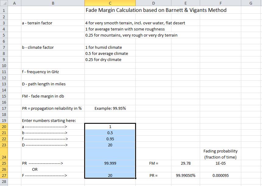
17 How to set a multipath fade margin (MFM)? First, decide on a propagation reliability (PR) over time. This is only one factor in overall system reliability however. From Barnett/Vigants model: Where: MFM = -10LOG[(1-PR)/(2.5x10-6 abfd 3 )] PR = fraction of time of path unavailability a = terrain factor b = climate factor f = frequency in GHz D = path length in miles
18
19
20
21 Other factors added to the fade margin Rain fade significant for >6 GHz and long paths, very complex problem to quantify Equipment aging includes antenna misalignment, DoD recommends 6 db though more would be appropriate for higher-gain dishes Atmospheric absorption only consider water vapor between 15 and 30 GHz, peaks at 22 GHz, estimate 0.2 db/km Use of multipath fade margin alone (plus allowance for rain > 10 GHz) is usually appropriate for gross planning below 20 GHz.
22 Estimated Rain Attenuation (RA) at Specific Frequencies for 1 /hr Rainfall Freq. (GHz) RA (db/km)
23 If your path has obstacles in the F.Z. and you can t increase the antenna heights to avoid them, how do you estimate the diffraction losses? From the path profile, determine the level of penetration of the 60% 1 st F.Z. of each obstacle and add the losses according to the diagram. Source: Lehpamer, H., Microwave Transmission Networks: Planning, Design, and Deployment (Second Edition), McGraw-Hill, 2010.
24 Putting together the radio link budget, with gains and losses Source: Lehpamer, H., Microwave Transmission Networks: Planning, Design, and Deployment (Second Edition), McGraw-Hill, 2010.
25 Calculation of Received Signal (RSL) with Fading RSL = P o -L tx + G atx -FSL -MFM -RA -L rc + G rc -L m P o = Transmitter power output (dbm) L tx = All losses between transmitter and its antenna (db) G atx = Gain of transmitting antenna (dbi) FSL = Free space loss (db) MFM = Multipath fade margin (db) RA = Rain attenuation (db) L rc = All losses between receiver and its antenna (db) G rc = Gain of receiving antenna (dbi) L m = Miscellaneous losses (obstacle, misalignment, aging) (db)
26 Example A digital QAM modulated radio link is to be built with a path distance of 25.5 km. Frequency is 11.0 GHz. Transmitter power is 23.0 dbm. Gain of both transmitting and receiving antennas is 37.6 dbi. The receiver threshold level is -75 dbm. Assume no combiner or transmission line losses. Rain attenuation is estimated to be 0.3 db/km for ½ rain per hour, or 7.7 db over the entire path. Assume no obstacle losses. A propagation reliability of 99.95% is desired. The MFM is calculated as 20.4 db for that reliability, assuming a terrain factor of 2 and a climate factor of Miscellaneous loss is assumed to be 6.0 db. RSL = = This is 2.3 db below the receiver threshold level.
27 A few things to watch out for The reliability (or availability) calculation does not include equipment failure or the reliability of your telecom company or ISP that delivers content to your microwave site. These have to be taken into account.
, McGraw-Hill, 2010.")
28 A radio link path mostly over water is a received signal cancellation hazard due to reflections from the surface. Antenna heights should be adjusted so that the 2 nd F.Z. is below the surface. Also, use vertical polarization instead of horizontal polarization. Source: Lehpamer, H., Microwave Transmission Networks: Planning, Design, and Deployment (Second Edition), McGraw-Hill, 2010.
29 Way to improve performance Adaptive modulation automatically reduces modulation rate as fading increases, so link is uninterrupted. Source: Lehpamer, H., Microwave Transmission Networks: Planning, Design, and Deployment (Second Edition), McGraw-Hill, 2010.
30 Ways to improve propagation reliability Frequency Diversity The signals are transmitting on two frequencies usually separated by 2%. Reduces fading by up to 15 db. Source: Lehpamer, H., Microwave Transmission Networks: Planning, Design, and Deployment (Second Edition), McGraw-Hill, 2010.
31 Space Diversity Two receiving antennas separated vertically by a spacing that creates two paths not simultaneously affected by fading. Separation can be between 100 and 200 wavelengths (e.g., for 6 GHz, between 16.5 and 33 feet). Source: Lehpamer, H., Microwave Transmission Networks: Planning, Design, and Deployment (Second Edition), McGraw-Hill, 2010.
32 Thanks for listening! Ben Evans, P.E. Evans Engineering Solutions
An Introduction to Microwave Radio Link Design
 An Introduction to Microwave Radio Link Design Table of Contents 1 Introduction... 3 2 Radio Link Engineering main steps... 3 2.1 Make Path profile... 3 2.2 Calculate Free Space Loss (FSL)... 4 2.3 Calculate
Understanding Range for RF Devices
 Understanding Range for RF Devices October 2012 White Paper Understanding how environmental factors can affect range is one of the key aspects to deploying a radio frequency (RF) solution. This paper will
This Antenna Basics reference guide includes basic information about antenna types, how antennas work, gain, and some installation examples.
 Antenna Basics This Antenna Basics reference guide includes basic information about antenna types, how antennas work, gain, and some installation examples. What Do Antennas Do? Antennas transmit radio
WiFi Long Shots Get the latest copy at www.scii.nl/~elektra. Elektra Wagenrad
 WiFi Long Shots Get the latest copy at www.scii.nl/~elektra Elektra Wagenrad Why? Building cheap infrastructure wherever ISP's don't see the chance of quick return of investment. Community Networks Add
AN INTRODUCTION TO TELEMETRY PART 1: TELEMETRY BASICS
 AN INTRODUCTION TO TELEMETRY PART 1: TELEMETRY BASICS Telemetry is defined as the sensing and measuring of information at some remote location and then transmitting that information to a central or host
Antennas & Propagation. CS 6710 Spring 2010 Rajmohan Rajaraman
 Antennas & Propagation CS 6710 Spring 2010 Rajmohan Rajaraman Introduction An antenna is an electrical conductor or system of conductors o Transmission - radiates electromagnetic energy into space o Reception
RECOMMENDATION ITU-R P.1546-1. Method for point-to-area predictions for terrestrial services in the frequency range 30 MHz to 3 000 MHz
 Rec. ITU-R P.546- RECOMMENDATION ITU-R P.546- Method for point-to-area predictions for terrestrial services in the frequency range 30 MHz to 3 000 MHz (200-2003) The ITU Radiocommunication Assembly, considering
Radio Physics for Wireless Devices and Networking. The Radio Physics of WiFi. By Ron Vigneri
 Radio Physics for Wireless Devices and Networking By Ron Vigneri The Radio Physics of WiFi The standard for wireless LANs (WLANs) was completed in 1997 with the release of the IEEE 802.11 specification
Antenna Deployment Technical Brief
 ProCurve Networking Antenna Deployment Technical Brief Introduction... 2 Antenna types... 2 Omni directional antennas... 2 Directional antennas... 2 Diversity antennas... 3 High gain directional antennas...
EE4367 Telecom. Switching & Transmission. Prof. Murat Torlak
 Path Loss Radio Wave Propagation The wireless radio channel puts fundamental limitations to the performance of wireless communications systems Radio channels are extremely random, and are not easily analyzed
Introduction to RF Engineering. Andrew CLEGG
 Introduction to RF Engineering Andrew CLEGG 1 Comparing the Lingo Radio Astronomers Speak a Unique Vernacular We are receiving interference from your transmitter at a level of 10 janskys What the ^#$&
Pointers on using the 5GHz WiFi bands
 Pointers on using the 5GHz WiFi bands Legalities In the UK, there are two main types of radio devices that use the 5GHz frequency bands. The most common are those devices that conform to the 11a standard.
Basics of Radio Wave Propagation
 Basics of Radio Wave Propagation Iulian Rosu, YO3DAC / VA3IUL, http://www.qsl.net/va3iul/ Propagation Modes Ground-wave propagation o Follows contour of the earth o Can Propagate considerable distances
Avaya WLAN 9100 External Antennas for use with the WAO-9122 Access Point
 Avaya WLAN 9100 External Antennas for use with the WAO-9122 Access Point Overview To optimize the overall performance of a WLAN in an outdoor deployment it is important to understand how to maximize coverage
Planning Terrestrial Radio Networks
 Planning Terrestrial Radio Networks Lab Exercise Manual IK2500 - Radio Communication, Basic Course September 23, 2008 Short Summary The scope of this lab is to help students to develop basic skills in
The Application of Land Use/ Land Cover (Clutter) Data to Wireless Communication System Design
 Data to Wireless Communication System Design") Technology White Paper The Application of Land Use/ Land Cover (Clutter) Data to Wireless Communication System Design The Power of Planning 1 Harry Anderson, Ted Hicks, Jody Kirtner EDX Wireless, LLC Eugene,
Technology White Paper The Application of Land Use/ Land Cover (Clutter) Data to Wireless Communication System Design The Power of Planning 1 Harry Anderson, Ted Hicks, Jody Kirtner EDX Wireless, LLC Eugene,
ITRAINONLINE MMTK BASIC RADIO PHYSICS HANDOUT
 ITRAINONLINE MMTK BASIC RADIO PHYSICS HANDOUT Developed by: Sebastian Buettrich, wire.less.dk Edited by: Alberto Escudero Pascual, IT +46 Table of Contents 1. About this document...1 1.1 Copyright information...2
RF Path Loss & Transmission Distance Calculations
 RF Path Loss & Transmission Distance Calculations By Walter Debus Director of Engineering Axonn, LLC Technical Memorandum August 4, 2006 INTRODUCTION DOC# 8545-0003-01 For radio transmission systems that
Wireless Networking over Extended Range
 Wireless Networking over Extended Range Technology options for optimizing long range wireless connectivity Technical Note This paper has been compiled using real life data collected over the last 5 years
Potential Effects of Wind Turbine Generators on Pre-Existing RF Communication Networks SEAN YUN. June 2009. Software Solutions in Radiocommunications
 Potential Effects of Wind Turbine Generators on Pre-Existing RF Communication Networks June 2009 SEAN YUN 2 2 Abstract In an effort to help preserve the ozone and the availability of diminishing natural
DVB-SH. Radio Network Planning Tool. (Release 4.2)
") DVB-SH Radio Network Planning Tool (Release 4.2) by AWE Communications GmbH. All rights reserved 1 1 Introduction 1.1 Overview Digital Video Broadcasting Satellite to Handheld (DVB-SH) aims to provide
DVB-SH Radio Network Planning Tool (Release 4.2) by AWE Communications GmbH. All rights reserved 1 1 Introduction 1.1 Overview Digital Video Broadcasting Satellite to Handheld (DVB-SH) aims to provide
SHARING BETWEEN TERRESTRIAL FLIGHT TELEPHONE SYSTEM (TFTS) AND RADIO ASTRONOMY IN THE 1.6 GHz BAND. Paris, May 1992
 AND RADIO ASTRONOMY IN THE 1.6 GHz BAND. Paris, May 1992") European Radiocommunications Committee (ERC) within the European Conference of Postal and Telecommunications Administrations (CEPT) SHARING BETWEEN TERRESTRIAL FLIGHT TELEPHONE SYSTEM (TFTS) AND RADIO
European Radiocommunications Committee (ERC) within the European Conference of Postal and Telecommunications Administrations (CEPT) SHARING BETWEEN TERRESTRIAL FLIGHT TELEPHONE SYSTEM (TFTS) AND RADIO
Cellular Wireless Antennas
 Cellular Wireless Antennas A Technical Brief GarrettCom Inc., November 2010 Overview The Cellular Wireless Antenna Technical brief is provided to assist with the design and deployment of the DX940 Cellular
Antenna Properties and their impact on Wireless System Performance. Dr. Steven R. Best. Cushcraft Corporation 48 Perimeter Road Manchester, NH 03013
 Antenna Properties and their impact on Wireless System Performance Dr. Steven R. Best Cushcraft Corporation 48 Perimeter Road Manchester, NH 03013 Phone (603) 627-7877 FAX: (603) 627-1764 Email: sbest@cushcraft.com
communication over wireless link handling mobile user who changes point of attachment to network
 Wireless Networks Background: # wireless (mobile) phone subscribers now exceeds # wired phone subscribers! computer nets: laptops, palmtops, PDAs, Internet-enabled phone promise anytime untethered Internet
Omni Antenna vs. Directional Antenna
 Omni Antenna vs. Directional Antenna Document ID: 82068 Contents Introduction Prerequisites Requirements Components Used Conventions Basic Definitions and Antenna Concepts Indoor Effects Omni Antenna Pros
COLLATED QUESTIONS: ELECTROMAGNETIC RADIATION
 COLLATED QUESTIONS: ELECTROMAGNETIC RADIATION 2011(2): WAVES Doppler radar can determine the speed and direction of a moving car. Pulses of extremely high frequency radio waves are sent out in a narrow
Just a Dipole. Gary Wescom N0GW July 16, 2007
 Just a Dipole Gary Wescom N0GW July 16, 2007 Often we will hear people describing their antennas as just a dipole. After all, a coax cable fed, half wavelength dipole is one of the simplest antennas to
WiFi Antenna Installation Best Practices Design Guide
 WiFi Antenna Installation Best Practices Design Guide Choosing the right antenna The first step to building a wireless network is choosing the correct antenna for your application. Coverage and range will
FURTHER READING: As a preview for further reading, the following reference has been provided from the pages of the book below:
 FURTHER READING: As a preview for further reading, the following reference has been provided from the pages of the book below: Title: Cellular/PCS Management Author: Paul Beddel Publisher: McGraw-Hill
Signal directionality Lower frequency signals are omnidirectional Higher frequency signals can be focused in a directional beam
 Transmission Media Transmission medium Physical path between transmitter and receiver May be guided (wired) or unguided (wireless) Communication achieved by using em waves Characteristics and quality of
Basic Outdoor WiFi Network Planning
 Basic Outdoor WiFi Network Planning Michael E Fox, N6MEF Santa Clara County ARES /RACES SIG Meeting 15 May 2014 Revised: 16 May 2014 ARES and Amateur Radio Emergency Service are registered service marks
UHF Wave Propagation Losses Beyond 40 Percent Fresnel Zone Radius in South-South, Nigeria
 UHF Wave Propagation Losses Beyond 40 Percent Fresnel Zone Radius in South-South, Nigeria D. E. Bassey 1, Aniefiok O. Akpan 2, E Udoeno 3 1 Electronics and Computer Technology Unit, Department of Physics,
Regional Emergency Communications. John Walters W8CX Alpena RACES
 Regional Emergency Communications John Walters W8CX Alpena RACES Regional Communications Needs 400 mile radius No skip zone; no dead spots No interference with or from broadcasters Reliable day/night coverage
You will need the following pieces of equipment to complete this experiment:
 UNIVERSITY OF TORONTO FACULTY OF APPLIED SCIENCE AND ENGINEERING The Edward S. Rogers Sr. Department of Electrical and Computer Engineering ECE422H1S: RADIO AND MICROWAVE WIRELESS SYSTEMS EXPERIMENT 3:
Technician Licensing Class
 Technician Licensing Class Antennas Presented by Amateur Radio Technician Class Element 2 Course Presentation ELEMENT 2 SUB-ELEMENTS (Groupings) About Ham Radio Call Signs Control Mind the Rules Tech Frequencies
Radio Network Planning Tools Basics, Practical Examples & Demonstration on NGN Network Planning Part I
 Radio Network Planning Tools Basics, Practical Examples & Demonstration on NGN Network Planning Part I Roland Götz LS telcom AG Regional Seminar on evolving network infrastructures to NGN and related Planning
Antenna Diversity in Wireless Local Area Network Devices
 Antenna Diversity in Wireless Local Area Network Devices Frank M. Caimi, Ph.D. Kerry L. Greer Jason M. Hendler January 2002 Introduction Antenna diversity has been used in wireless communication systems
International Civil Aviation Organization
 CNS/MET SG/16 IP/30 (Rev.) Agenda Item 7 (3) 23/07/12 International Civil Aviation Organization SIXTEENTH MEETING OF THE COMMNICATIONS/NAVIGATION/SRVEILLANCE AND METEOROLOGY SB-GROP (CNS/MET SG/16) OF
Remarkable achievements
 Remarkable achievements 149.2 km link over water providing 8E1 throughput with 99,99% annual availability Radio link transmitting data from 25km height in Stratosphere to 149km ground station Largest MW
Wireless Internet. Is an system to provide connectivity to customers to the Internet. Service Provider (WISP) TECHNICAL INFO.
 TECHNICAL INFO.") Description The Service Provider System (WISP) is an integrated Metropolitan Area Network (MAN) system of connecting customers to the. High-speed wireless data links are used to provide access on a point-to-point
Description The Service Provider System (WISP) is an integrated Metropolitan Area Network (MAN) system of connecting customers to the. High-speed wireless data links are used to provide access on a point-to-point
Part I: Wireless System Characteristics
 Part I: Wireless System Characteristics Smart grid technology holds great promise of cleaner air, more efficient power, and lower greenhouse gas emissions. In a smart grid system, the system itself will
FADE MARGINS PREDICTION FOR BROADBAND FIXED WIRELESS ACCESS (BFWA) FROM MEASURE- MENTS IN TROPICS
 FROM MEASURE- MENTS IN TROPICS") Progress In Electromagnetics Research C, Vol. 11, 199 212, 2009 FADE MARGINS PREDICTION FOR BROADBAND FIXED WIRELESS ACCESS (BFWA) FROM MEASURE- MENTS IN TROPICS M. R. Ul Islam, T. A. Rahman, S. K. A.
Progress In Electromagnetics Research C, Vol. 11, 199 212, 2009 FADE MARGINS PREDICTION FOR BROADBAND FIXED WIRELESS ACCESS (BFWA) FROM MEASURE- MENTS IN TROPICS M. R. Ul Islam, T. A. Rahman, S. K. A.
Amplification of the Radiation from Two Collocated Cellular System Antennas by the Ground Wave of an AM Broadcast Station
 Amplification of the Radiation from Two Collocated Cellular System Antennas by the Ground Wave of an AM Broadcast Station Dr. Bill P. Curry EMSciTek Consulting Co., W101 McCarron Road Glen Ellyn, IL 60137,
RADIO WAVE TRANSMISSION PRINCIPLES. What Are Radio Waves? 74 Chapter 3 How Wireless Works
 3 C H A P T E R T H R E E HOW WIRELESS WORKS Copyright 2005 by Course Technology. All rights reserved.this publication is protected by federal copyright law. No part of this publication 73 74 Chapter 3
COMPATIBILITY AND SHARING ANALYSIS BETWEEN DVB T AND RADIO MICROPHONES IN BANDS IV AND V
 European Radiocommunications Committee (ERC) within the European Conference of Postal and Telecommunications Administrations (CEPT) COMPATIBILITY AND SHARING ANALYSIS BETWEEN DVB T AND RADIO MICROPHONES
GSM frequency planning
 GSM frequency planning Band : 890-915 and 935-960 MHz Channel spacing: 200 khz (but signal bandwidth = 400 khz) Absolute Radio Frequency Channel Number (ARFCN) lower band: upper band: F l (n) = 890.2 +
Module 13 : Measurements on Fiber Optic Systems
 Module 13 : Measurements on Fiber Optic Systems Lecture : Measurements on Fiber Optic Systems Objectives In this lecture you will learn the following Measurements on Fiber Optic Systems Attenuation (Loss)
Alternative Wireless Access Technologies. Heinz Willebrand, CEO & President
 Alternative Wireless Access Technologies Heinz Willebrand, CEO & President The Mobile Wireless Backhaul Dilemma Backhaul Capacity Requirements Increasing Single 4G/LTE base station capacity requirement
An Algorithm for Automatic Base Station Placement in Cellular Network Deployment
 An Algorithm for Automatic Base Station Placement in Cellular Network Deployment István Törős and Péter Fazekas High Speed Networks Laboratory Dept. of Telecommunications, Budapest University of Technology
Hang Em High: Options for antennas, masts and towers
 Hang Em High: Options for antennas, masts and towers Antennas play an important role in radio broadcasting. The antenna is the piece of equipment which gets your signal out to the audience you want to
ABHELSINKI UNIVERSITY OF TECHNOLOGY
 Basic of Propagation Theory S-72.333 Physical Layer Methods in Wireless Communication Systems Fabio Belloni Helsinki University of Technology Signal Processing Laboratory fbelloni@wooster.hut.fi 23 November
is the power reference: Specifically, power in db is represented by the following equation, where P0 P db = 10 log 10
 RF Basics - Part 1 This is the first article in the multi-part series on RF Basics. We start the series by reviewing some basic RF concepts: Decibels (db), Antenna Gain, Free-space RF Propagation, RF Attenuation,
VHF/UHF/Microwave Radio Propagation: A Primer for Digital Experimenters
 VHF/UHF/Microwave Radio Propagation: A Primer for Digital Experimenters Barry McLarnon, VE3JF 2696 Regina St. Ottawa, ON K2B 6Yl ve3jfatapr.org Abstract This paper attempts to provide some insight into
High Performance Wireless Networking and Weather
 High Performance Wireless Networking and Weather Jose Otero, Pavana Yalamanchili, Hans-Werner Braun Abstract High performance wireless networking is effected by a number of internal and external variables.
102 26-m Antenna Subnet Telecommunications Interfaces
 DSMS Telecommunications Link Design Handbook 26-m Antenna Subnet Telecommunications Interfaces Effective November 30, 2000 Document Owner: Approved by: Released by: [Signature on file in TMOD Library]
MICROWAVE ANTENNA PATTERN WITH DIFFERENT PARAMETER EVALUATION IN MOBILE ENVIRONMENT
 www.arpapress.com/volumes/vol9issue1/ijrras_9_1_07.pdf MICROWAVE ANTENNA PATTERN WITH DIFFERENT PARAMETER EVALUATION IN MOBILE ENVIRONMENT 1,* D.S. Ramkiran, 2 A.RamaKrishna, 1 Ch.Radhika & 1 B.T.P.Madhav
The road and the buildings on each side of the road can
 Alternative RF Planning Solutions for Coverage Deficiency Aleksey A. Kurochkin aakuroch@bechtel.com Issue Date: December 2002 INTRODUCTION This paper introduces a few of the more common alternatives to
Chapter 4 Solution to Problems
 Chapter 4 Solution to Problems Question #1. A C-band earth station has an antenna with a transmit gain of 54 db. The transmitter output power is set to 100 W at a frequency of 6.100 GHz. The signal is
1. Introduction. FER-Zagreb, Satellite communication systems 2011/12
 1. Introduction Topics History Characteristics of satellite communications Frequencies Application 1 History Arthur C. Clark suggested in 1945. Earth coverage with 3 geostationary satellites. On 4th of
Electronic Communications Committee (ECC) within the Conference of Postal and Telecommunications Administrations (CEPT)
 within the Conference of Postal and Telecommunications Administrations (CEPT)") Page 1 Electronic Communications Committee (ECC) within the Conference of Postal and Telecommunications Administrations (CEPT) ECC RECOMMENDATION (05)08 (replacing recommendations T/R 20-08 and 22-07)
Page 1 Electronic Communications Committee (ECC) within the Conference of Postal and Telecommunications Administrations (CEPT) ECC RECOMMENDATION (05)08 (replacing recommendations T/R 20-08 and 22-07)
I. Wireless Channel Modeling
 I. Wireless Channel Modeling April 29, 2008 Qinghai Yang School of Telecom. Engineering qhyang@xidian.edu.cn Qinghai Yang Wireless Communication Series 1 Contents Free space signal propagation Pass-Loss
Preview of Period 3: Electromagnetic Waves Radiant Energy II
 Preview of Period 3: Electromagnetic Waves Radiant Energy II 3.1 Radiant Energy from the Sun How is light reflected and transmitted? What is polarized light? 3.2 Energy Transfer with Radiant Energy How
RF Communication System. EE 172 Systems Group Presentation
 RF Communication System EE 172 Systems Group Presentation RF System Outline Transmitter Components Receiver Components Noise Figure Link Budget Test Equipment System Success Design Remedy Transmitter Components
Title: "Fixed-link wind-turbine exclusion zone method" Author: D F Bacon Status: released 28 Oct '02 Version: 1.1
 Title: "Fixed-link wind-turbine exclusion zone method" Author: D F Bacon Status: released 8 Oct '0 Version: 1.1 A proposed method for establishing an exclusion zone around a terrestrial fixed radio link
Microwave QSOs with the aid of airplane reflection. Wolf-Henning Rech DF9IC in JN48iw http://www.df9ic.de
 Microwave QSOs with the aid of airplane reflection Wolf-Henning Rech DF9IC in JN48iw http://www.df9ic.de Content Some theory Observations on beacons Experience from QSOs Airplane tracking with ADS-B A
Motion Sensing without Sensors: Information. Harvesting from Signal Strength Measurements
 Motion Sensing without Sensors: Information Harvesting from Signal Strength Measurements D. Puccinelli and M. Haenggi Department of Electrical Engineering University of Notre Dame Notre Dame, Indiana,
Human Exposure Limits
 Human Exposure Limits Session 3 0 Version December 2014 Learning objectives In this session we will: Learn about the international exposure limits for workers and the public Learn about methods for assessing
ENTERPRISE. Functionality chart
 ENTERPRISE Functionality chart Cellular Expert Enterprise module features Tasks Network data management Site, sector, construction, customer, repeater management: Add Edit Move Copy Delete Site re-use
RF Propagation: A Study of WiFi Design for the Department of Veterans
 Leveraging People, Processes, and Technology RF Propagation: A Study of WiFi Design for the Department of Veterans Affairs A White Paper Author: Damon House, Program Manager 11 Canal Center Plaza, Floor
General GPS Antenna Information APPLICATION NOTE
 General GPS Antenna Information APPLICATION NOTE General GPS Antenna Information Global Positioning System and Precise Time & Frequency The Global Positioning System (GPS) is a worldwide radio-navigation
Rain Attenuation Prediction for Terrestrial Microwave Link in Bangladesh
 Journal of Electrical and Electronics Engineering 63 Rain Attenuation Prediction for Terrestrial Microwave Link in Bangladesh HOSSAIN Sakir International Islamic University Chittagong, Bangladesh, Department
ElvaLink PPC-100 Series of mm-wave digital radios are designed to provide 100 Mbps connectivity to a wide variety of applications.
 ElvaLink PPC-1 Series of mm-wave digital radios are designed to provide 1 Mbps connectivity to a wide variety of applications. As an IP-packet transparent wireless bridge ElvaLink is easily deployed in
Optical Fibres. Introduction. Safety precautions. For your safety. For the safety of the apparatus
 Please do not remove this manual from from the lab. It is available at www.cm.ph.bham.ac.uk/y2lab Optics Introduction Optical fibres are widely used for transmitting data at high speeds. In this experiment,
Radio Frequency Propagation Mechanisms and Empirical Models for Hilly Areas
 International Journal of Electrical and Computer Engineering (IJECE) Vol. 3, No. 3, June 2013, pp. 372~376 ISSN: 2088-8708 372 Radio Frequency Propagation Mechanisms and Empirical Models for Hilly Areas
Method for point-to-area predictions for terrestrial services in the frequency range 30 MHz to 3 000 MHz
 Recommendation ITU-R P.546-5 (09/203) Method for point-to-area predictions for terrestrial services in the frequency range 30 MHz to 3 000 MHz P Series Radiowave propagation ii Rec. ITU-R P.546-5 Foreword
Design Considerations for RF Energy Harvesting Devices
 Design Considerations for RF Energy Harvesting Devices Harry Ostaffe Director, Marketing & Business Development 1 Overview RF energy is generally very low Direct-power at close range to a transmitter Energy
A Rural Broadband Model
 A simplified guide to assist those in rural America to determine the feasibility, costs, and technologies available for a rural broadband project. Created by the Yurok Tribe Information Services Department
Design and Certification of ASH Radio Systems for Japan
 Design and Certification of ASH Radio Systems for Japan RFM s second-generation ASH radio hybrids are being used in a wide variety of applications in Japan, operating under the Japanese BIJAKU radio regulations.
Outdoor Propagation Prediction in Wireless Local Area Network (WLAN)
") Outdoor Propagation Prediction in Wireless Local Area Network (WLAN) Akpado K.A 1, Oguejiofor O.S 1, Abe Adewale 2, Femijemilohun O.J 2 1 Department of Electronic and Computer Engineering, Nnamdi Azikiwe
Outdoor Propagation Prediction in Wireless Local Area Network (WLAN) Akpado K.A 1, Oguejiofor O.S 1, Abe Adewale 2, Femijemilohun O.J 2 1 Department of Electronic and Computer Engineering, Nnamdi Azikiwe
Attaching the PA-A1-ATM Interface Cables
 CHAPTER 4 Attaching the PA-A1-ATM Interface Cables To continue your PA-A1-ATM port adapter installation, you must attach the port adapter cables. The instructions that follow apply to all supported platforms.
Spectrum Compact: Revolutionary 6-40GHz Spectrum Analyzer
 Spectrum Compact: Revolutionary 6-40GHz Spectrum Analyzer #$%&"'(")*+,&-./"01/*%,&2"! An ultra light and easy to use measurement solution for the 6-40 GHz licensed and license-free microwave frequency
Analysis of radio wave propagation in Lagos environs
 AMERICAN JOURNAL OF SCIENTIFIC AND INDUSTRIAL RESEARCH 2011, Science Huβ, http://www.scihub.org/ajsir ISSN: 2153-649X doi:10.5251/ajsir.2011.2.3.438.455 Analysis of radio wave propagation in Lagos environs
Antenna Height and Communications Effectiveness
 Antenna Height and Communications Effectiveness Second Edition A Guide for City Planners and Amateur Radio Operators By R. Dean Straw, N6BV, and Gerald L. Hall, K1TD Senior Assistant Technical Editor and
RECOMMENDATION ITU-R F.1113. (Question ITU-R 157/9) b) that systems using this mode of propagation are already in service for burst data transmission,
 b) that systems using this mode of propagation are already in service for burst data transmission,") Rec. ITU-R F.1113 1 RECOMMENDATION ITU-R F.1113 RADIO SYSTEMS EMPLOYING METEOR-BURST PROPAGATION (Question ITU-R 157/9) (1994) Rec. ITU-R F.1113 The ITU Radiocommunication Assembly, considering a) that
Rec. ITU-R F.1113 1 RECOMMENDATION ITU-R F.1113 RADIO SYSTEMS EMPLOYING METEOR-BURST PROPAGATION (Question ITU-R 157/9) (1994) Rec. ITU-R F.1113 The ITU Radiocommunication Assembly, considering a) that
Lecture 3: Fibre Optics
 Lecture 3: Fibre Optics Lecture aims to explain: 1. Fibre applications in telecommunications 2. Principle of operation 3. Single- and multi-mode fibres 4. Light losses in fibres Fibre is a transparent
RECOMMENDATION ITU-R S.524-5. (Questions ITU-R 48/4 and ITU-R 70/4)
") Rec. ITU-R S.524-5 1 RECOMMENDATION ITU-R S.524-5 MAXIMUM PERMISSIBLE LEVELS OF OFF-AXIS e.i.r.p. DENSITY FROM EARTH STATIONS IN THE FIXED-SATELLITE SERVICE TRANSMITTING IN THE 6 AND 14 GHz FREQUENCY BANDS
Rec. ITU-R S.524-5 1 RECOMMENDATION ITU-R S.524-5 MAXIMUM PERMISSIBLE LEVELS OF OFF-AXIS e.i.r.p. DENSITY FROM EARTH STATIONS IN THE FIXED-SATELLITE SERVICE TRANSMITTING IN THE 6 AND 14 GHz FREQUENCY BANDS
Internal GPS Active Patch Antenna Application Note
 Internal GPS Active Patch Antenna Application Note APN-13-8-002/A Page 1 of 14 1. BASICS 2. APPLICATIONS 3. SIZE 4. SHAPE 5. GROUND PLANE 6. IMPEDANCE 7. BANDWIDTH 8. VSWR 9. LINK BUDGET 10. GAIN 11. NOISE
Selecting Receiving Antennas for Radio Tracking
 Selecting Receiving Antennas for Radio Tracking Larry B Kuechle, Advanced Telemetry Systems, Inc. Isanti, Minnesota 55040 lkuechle@atstrack.com The receiving antenna is an integral part of any radio location
What is the Real Cost of Poor Quality Antennas?
 White Paper What is the Real Cost of Poor Quality Antennas? Jim Syme Product Line Manager, Microwave Systems October 2015 Contents Introduction 3 The Theory behind Compliance 3 The Real World 4 Conclusion
Nigerian Communications Commission
 Nigerian Communications Commission REGULATORY GUIDELINES FOR THE USE OF 2.4 GHz ISM BAND FOR COMMERCIAL TELECOM SERVICES Introduction The use of broadband for last mile access or for final distribution
Antenna Basic Concepts
 ANTENNA An antenna is a device to transmit and/or receive electromagnetic waves. Electromagnetic waves are often referred to as radio waves. Most antennas are resonant devices, which operate efficiently
AS COMPETITION PAPER 2008
 AS COMPETITION PAPER 28 Name School Town & County Total Mark/5 Time Allowed: One hour Attempt as many questions as you can. Write your answers on this question paper. Marks allocated for each question
FIRERAY 2000 Installation Guide
 FIRERAY 2000 Installation Guide Features Range 33ft to 330 ft. 24Vdc operation Selectable alarm thresholds Low current consumption Ground level electronics Manual or Automatic reset System Description
BMS Primer on Microwave Downlinks for Public Safety & Law Enforcement
 BMS Primer on Microwave Downlinks for Public Safety & Law Enforcement Prepared by: Steve Yanke Broadcast Microwave Services, Inc. P.O. Box 84630 San Diego, CA 92138 Phone: 1.858.391.3050 Web: www.bms-inc.com
Characteristics of terrestrial IMT-Advanced systems for frequency sharing/ interference analyses
 Report ITU-R M.2292-0 (12/2013) Characteristics of terrestrial IMT-Advanced systems for frequency sharing/ interference analyses M Series Mobile, radiodetermination, amateur and related satellite services
OUTLOOK. Considerations in the Choice of Suitable Spectrum for Mobile Communications. Visions and research directions for the Wireless World
 OUTLOOK Visions and research directions for the Wireless World November 2008, No 2 Considerations in the Choice of Suitable Spectrum for Mobile Communications WG8 White Paper Considerations in the Choice
Engineering Sciences 151. Electromagnetic Communication Laboratory Assignment 3 Fall Term 1998-99
 Engineering Sciences 151 Electromagnetic Communication Laboratory Assignment 3 Fall Term 1998-99 WAVE PROPAGATION II: HIGH FREQUENCY SLOTTED LINE AND REFLECTOMETER MEASUREMENTS OBJECTIVES: To build greater
Feedback Alarm and Its Troubleshooting For Improvement of Microwave Link
 IOSR Journal of Electronics and Communication Engineering (IOSR-JECE) e-issn: 2278-2834,p- ISSN: 2278-8735.Volume 9, Issue 2, Ver. VIII (Mar - Apr. 2014), PP 15-24 Feedback Alarm and Its Troubleshooting
Features of Corona 2.4GHz transmitting module and receiver. The new lightweight, advanced technology unit has the following features:
 Instruction Manual Corona 2.4GHz RF module & Receiver Thank you for purchasing our Corona 2.4Ghz RF transmitter module & receiver. In order to fully utilize the performance potential of this system, we