Week 11 - Lecture Dynamic Motion Simulation. ME Introduction to CAD/CAE Tools
|
|
|
- Betty Simmons
- 7 years ago
- Views:
Transcription
1 Week 11 - Lecture Dynamic Motion Simulation
2 Lecture Topics Dynamic Simulation Overview Common Use Cases and Terms Dynamic Simulation Workflow Joint Properties and Types Dynamic Simulation Results Autodesk Inventor Professional
3 Product Lifecycle Week 11 Requirements Portfolio Management Conceptual Design Product Engineering Manufacturing Engineering Simulation & Validation Build & Produce Disposal & Recycling Maintenance & Repair Sales & Distribution Test & Quality

4 Dynamic Simulation Creation of motion simulations based on position, velocity, acceleration, and torque as functions of time with external loads on rigid body assembly mechanisms.

5 Dynamic Simulation Benefits Reduce Physical Prototypes Explore Design Options (Early) Improve / Optimize Design Performance Validate Designs Gain Insights for Additional Analysis (FEA)

6 Use Case Examples What is the time to complete an operation? Will this force be able to lift the object? What size motor should we use? Will this shape provide the correct motion? How much force is required? What is the force being applied to this part?

7 Terms Kinematics Describes the motion of objects without consideration of forces. Dynamic Simulation Study of masses and inertial forces acting on a mechanism. Rigid Body Dynamics Objects that have geometrical properties like center of mass and moments of inertia that characterize motion in six degrees of freedom.
8 Dynamic Simulation Workflow The common dynamic simulation workflow is as follows: Step 1 = Preparation Step 2 = Creation of Joints Step 3 = Add External Forces Step 4 = Simulate and Analyze Results

9 Step 1 - Preparation Group components that have no relative motion between them. Manage using assembly structure like subassemblies in main design environment. Manage welding components together into groups within just the simulation environment. Ensure all components have proper materials properties assigned.

10 Joint Description Joints are links between two rigid components. A joint applies force from the first component on the second component. Joint coordinate systems are used to define motions and efforts in the joint.
11 Step 2 - Creating Joints Creating joints is the most important element of dynamic simulation. Time consuming process. Joints control the Degree of Freedom and assign properties like friction and damping.

12 Standard Mechanical Joint Revolution Joint 0 Translation DOF 1 Rotation DOF


13 Special Joints Belts Gears Springs Contacts


14 Difference between Constraints and Joints An assembly constraint only respects geometry where as joints contain information like velocity, acceleration, and loads.

15 Kinematic Chain Series of components linked by joints. An open chain is attached at only one end. A closed chain, or a loop, is attached to a component at both ends.

16 Kinematic Model Group containing at least one kinematic chain beginning from a grounded part. A kinematic model can contain any number of kinematic chains, open or closed.

17 Common Joint Properties Restitution Indicates the normal velocity of two components after shock. A value of 1 would indicate the object is completely elastic where 0 would be inelastic. Friction The coefficient of friction is the ratio that defines the force that resists the motion of one body in contact with another. The most common values are between 0 and 0.2

18 Step 3 External Forces External forces need to be taken into account to ensure all factors are defined that control movement in the simulation. Common external forces are: Gravity Force Load Torque Load
19 Step 4 Review Results Once the simulation is completed you can analyze and compare results like: Reaction forces Velocities Acceleration Moments Displacement

20 Autodesk Inventor Professional Dynamic Simulation Environment Rigid Body Dynamics Linear Dynamic Analysis Standard and Special Joints Output data for FEA
21 Standard Joints Dynamic Simulation Joints D.O.F. Revolution No Translation Rotation around the Z Axis 1 Prismatic Translation along the Z Axis No Rotation 1 Cylindrical Translation along the Z Axis Rotation around the Z Axis 2 Spherical No Translation Rotation along all 3 Axis 3 Planar Translation along the X and Z Axis Rotation about the Y Axis 3
22 Standard Joints Dynamic Simulation Joints D.O.F. Point - Line Translation along the Z axis Rotation around all 3 Axis 4 Line - Plane Point - Plane Translation along the X and Z Axis Rotation about the Y Axis Translation along the X and Z Axis Rotation around all 3 Axis 3 5 Spatial Welding Translation along all 3 Axis Rotation about all 3 Axis No Translation No Rotation 6 0
23 Rolling Joints RI Cylinder on Plane Dynamic Simulation Joints This allows motion between a cylinder and plane D.O.F. N/A RI Cylinder on Cylinder RI Cylinder in Cylinder RI Cylinder Curve Belt RI Cone on Plane RI Cone in Cone Screw Worm Gear This allows motion between two primitive cylindrical components in opposite directions. This allows motion between a rotating cylinder inside another non rotating cylinder. This allows motion between a rotating cylinder and a rotating CAM. This creates motion of two cylinders with the same speed. This allows motion between a conical face and a planar face. This allows motion of a rotating conical component within a stationary conical component. This is the same as a cylindrical component but allows the user to specify pitch. This allows motion between a worm gear component and a helical gear component. N/A N/A N/A N/A N/A N/A N/A N/A

24 Sliding & Special Joints
25 Output Grapher Primary location for reviewing and comparing result data.
26 Computer-Cluster Projects (CP11)

27 Guided Lab Project 1 Guides instructions for completing a dynamic simulation on a cam and value assembly.

28 Guided Lab Project 2 Guided instructions for creating mechanical joints in the dynamic simulation.

29 Guided Lab Project 3 Guided instructions for completing a study of the windshield wiper assembly in dynamic simulation.

30 Problem Set Assignment Simulation the automotive seat lift mechanism to determine changes required to utilize a new motor.
31 Demo Topics

32 User Interface Dynamic Simulation tab Dynamic Simulation panels Dynamic Simulation tool Dynamic Simulation browser Simulation Player
33 Dynamic Simulation Panels
34 Dynamic Simulation Browser

35 Joint Redundancies
36 Joint Properties

37 External Forces Force Location Load Direction Magnitude of the Load Fixed / Associative Load Direction Vector Based Load Direction Display Load Glyph

38 Input Grapher Graph Region Reference button Command Buttons Starting Point End Point Property of the Select Sector
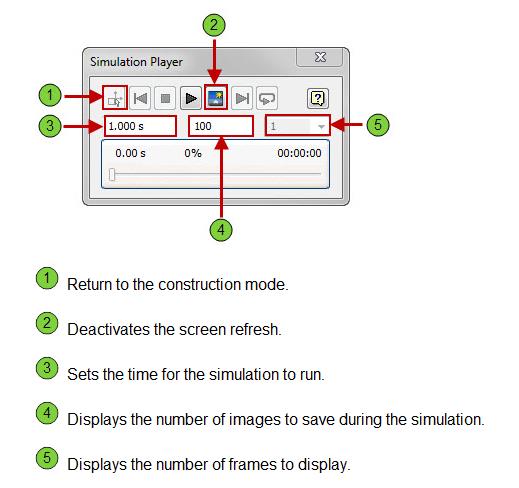
39 Simulation Player

40 Output Grapher
ME 24-688 Week 11 Introduction to Dynamic Simulation
 The purpose of this introduction to dynamic simulation project is to explorer the dynamic simulation environment of Autodesk Inventor Professional. This environment allows you to perform rigid body dynamic
Chapter. 4 Mechanism Design and Analysis
 Chapter. 4 Mechanism Design and Analysis 1 All mechanical devices containing moving parts are composed of some type of mechanism. A mechanism is a group of links interacting with each other through joints
How To Understand The Relationship Between A Body And A Joint
 Degree of Freedom No. of independent coordinates needed to define position of body How many DOF does a body in three-space (3-D) have? Definitions All of the above contain linkages which consist of: Links
Using Design Accelerators in Autodesk Inventor
 Using Design Accelerators in Autodesk Inventor Ravi Akella Autodesk, Inc. Ales Ricar Autodesk, Inc. MA 201-3P Getting things in gear are easy with the Design Accelerators in Autodesk Inventor. Find out
Computer Aided Design (CAD), ME 530.414, JHU Professor Dan Stoianovici, dss@jhu.edu
, ME 530.414, JHU Professor Dan Stoianovici, dss@jhu.edu") Computer Aided Design (CAD), ME 530.414, JHU Professor Dan Stoianovici, dss@jhu.edu COURSE DESCRIPTION: The course outlines modern solid modeling design, analysis, simulation, and manufacturing of mechanical
Computer Aided Design (CAD), ME 530.414, JHU Professor Dan Stoianovici, dss@jhu.edu COURSE DESCRIPTION: The course outlines modern solid modeling design, analysis, simulation, and manufacturing of mechanical
Figure 3.1.2 Cartesian coordinate robot
 Introduction to Robotics, H. Harry Asada Chapter Robot Mechanisms A robot is a machine capable of physical motion for interacting with the environment. Physical interactions include manipulation, locomotion,
CATIA V5 Tutorials. Mechanism Design & Animation. Release 18. Nader G. Zamani. University of Windsor. Jonathan M. Weaver. University of Detroit Mercy
 CATIA V5 Tutorials Mechanism Design & Animation Release 18 Nader G. Zamani University of Windsor Jonathan M. Weaver University of Detroit Mercy SDC PUBLICATIONS Schroff Development Corporation www.schroff.com
Animations in Creo 3.0
 Animations in Creo 3.0 ME170 Part I. Introduction & Outline Animations provide useful demonstrations and analyses of a mechanism's motion. This document will present two ways to create a motion animation
Physics 9e/Cutnell. correlated to the. College Board AP Physics 1 Course Objectives
 Physics 9e/Cutnell correlated to the College Board AP Physics 1 Course Objectives Big Idea 1: Objects and systems have properties such as mass and charge. Systems may have internal structure. Enduring
Week 4 - Lecture Assemblies. ME 24-688 Introduction to CAD/CAE Tools
 Week 4 - Lecture Assemblies Lecture Topics Assemblies and Product Structure Bill of Materials PLM Role and Definition Design for Assembly Overview Case Study Examples Product Lifecycle Week 4 Requirements
Lecture L22-2D Rigid Body Dynamics: Work and Energy
 J. Peraire, S. Widnall 6.07 Dynamics Fall 008 Version.0 Lecture L - D Rigid Body Dynamics: Work and Energy In this lecture, we will revisit the principle of work and energy introduced in lecture L-3 for
Design and Modeling of Fluid Power Systems ME 597/ABE 591 Lecture 5
 Systems ME 597/ABE 591 Lecture 5 Dr. Monika Ivantysynova MAHA Professor Fluid Power Systems MAHA Fluid Power Research Center Purdue University Displacement Machines Study different design principles and
Simulation-News in Creo 1.0. Urs Simmler MCAD Simulation Specialist
 Simulation-News in Creo 1.0 Urs Simmler MCAD Simulation Specialist MECHANICA-News in Creo 1.0 Urs Simmler MCAD Simulation Specialist Creo Simulation App Standalone Mechanica Application > Dedicated User
Véronique PERDEREAU ISIR UPMC 6 mars 2013
 Véronique PERDEREAU ISIR UPMC mars 2013 Conventional methods applied to rehabilitation robotics Véronique Perdereau 2 Reference Robot force control by Bruno Siciliano & Luigi Villani Kluwer Academic Publishers
Manufacturing Equipment Modeling
 QUESTION 1 For a linear axis actuated by an electric motor complete the following: a. Derive a differential equation for the linear axis velocity assuming viscous friction acts on the DC motor shaft, leadscrew,
Precise Modelling of a Gantry Crane System Including Friction, 3D Angular Swing and Hoisting Cable Flexibility
 Precise Modelling of a Gantry Crane System Including Friction, 3D Angular Swing and Hoisting Cable Flexibility Renuka V. S. & Abraham T Mathew Electrical Engineering Department, NIT Calicut E-mail : renuka_mee@nitc.ac.in,
Selecting and Sizing Ball Screw Drives
 Selecting and Sizing Ball Screw Drives Jeff G. Johnson, Product Engineer Thomson Industries, Inc. Wood Dale, IL 540-633-3549 www.thomsonlinear.com Thomson@thomsonlinear.com Fig 1: Ball screw drive is a
MET 306. Activity 8a. Mechanism Design Creo 2.0 Level 7 POINT A GROUND LINK LINK 1 LINK 2 LINK 3 POINT B 10/15/2010 1
 Mechanism Design Creo 2.0 Level 7 POINT A LINK 1 GROUND LINK LINK 2 LINK 3 POINT B 10/15/2010 1 Download parts ground, key, link_1, link_2, link_3 and pulley from the V:/MET_306/Activity_8_Creo drive.
Practice Exam Three Solutions
 MASSACHUSETTS INSTITUTE OF TECHNOLOGY Department of Physics Physics 8.01T Fall Term 2004 Practice Exam Three Solutions Problem 1a) (5 points) Collisions and Center of Mass Reference Frame In the lab frame,
COMPUTATIONAL ENGINEERING OF FINITE ELEMENT MODELLING FOR AUTOMOTIVE APPLICATION USING ABAQUS
 International Journal of Advanced Research in Engineering and Technology (IJARET) Volume 7, Issue 2, March-April 2016, pp. 30 52, Article ID: IJARET_07_02_004 Available online at http://www.iaeme.com/ijaret/issues.asp?jtype=ijaret&vtype=7&itype=2
Lecture L2 - Degrees of Freedom and Constraints, Rectilinear Motion
 S. Widnall 6.07 Dynamics Fall 009 Version.0 Lecture L - Degrees of Freedom and Constraints, Rectilinear Motion Degrees of Freedom Degrees of freedom refers to the number of independent spatial coordinates
Modeling Mechanical Systems
 chp3 1 Modeling Mechanical Systems Dr. Nhut Ho ME584 chp3 2 Agenda Idealized Modeling Elements Modeling Method and Examples Lagrange s Equation Case study: Feasibility Study of a Mobile Robot Design Matlab
HW Set VI page 1 of 9 PHYSICS 1401 (1) homework solutions
 homework solutions") HW Set VI page 1 of 9 10-30 A 10 g bullet moving directly upward at 1000 m/s strikes and passes through the center of mass of a 5.0 kg block initially at rest (Fig. 10-33 ). The bullet emerges from the
HW Set VI page 1 of 9 10-30 A 10 g bullet moving directly upward at 1000 m/s strikes and passes through the center of mass of a 5.0 kg block initially at rest (Fig. 10-33 ). The bullet emerges from the
Mechanics lecture 7 Moment of a force, torque, equilibrium of a body
 G.1 EE1.el3 (EEE1023): Electronics III Mechanics lecture 7 Moment of a force, torque, equilibrium of a body Dr Philip Jackson http://www.ee.surrey.ac.uk/teaching/courses/ee1.el3/ G.2 Moments, torque and
Academic Crosswalk to Common Core Standards. REC ELA.RST.11-12.3 LA.12.1.6.k LA.12.3.2
 Introduction to Robotics Course Description NHT Introduction to Robotics (IR) is designed to explore the current and future use of automation technology in industry and everyday use. Students will receive
Physics 2A, Sec B00: Mechanics -- Winter 2011 Instructor: B. Grinstein Final Exam
 Physics 2A, Sec B00: Mechanics -- Winter 2011 Instructor: B. Grinstein Final Exam INSTRUCTIONS: Use a pencil #2 to fill your scantron. Write your code number and bubble it in under "EXAM NUMBER;" an entry
UNIT II Robots Drive Systems and End Effectors Part-A Questions
 UNIT II Robots Drive Systems and End Effectors Part-A Questions 1. Define End effector. End effector is a device that is attached to the end of the wrist arm to perform specific task. 2. Give some examples
Up and Running with Autodesk Inventor Professional Simulation in 90 Minutes!
 Up and Running with Autodesk Inventor Professional Simulation in 90 Minutes! Wasim Younis - Author of Up and Running Inventor Professional Simulation books MA2038 - This class will present a workflow for
Salem Community College Course Syllabus. Course Title: Physics I. Course Code: PHY 101. Lecture Hours: 2 Laboratory Hours: 4 Credits: 4
 Salem Community College Course Syllabus Course Title: Physics I Course Code: PHY 101 Lecture Hours: 2 Laboratory Hours: 4 Credits: 4 Course Description: The basic principles of classical physics are explored
Center of Gravity. We touched on this briefly in chapter 7! x 2
 Center of Gravity We touched on this briefly in chapter 7! x 1 x 2 cm m 1 m 2 This was for what is known as discrete objects. Discrete refers to the fact that the two objects separated and individual.
Physics 1A Lecture 10C
 Physics 1A Lecture 10C "If you neglect to recharge a battery, it dies. And if you run full speed ahead without stopping for water, you lose momentum to finish the race. --Oprah Winfrey Static Equilibrium
ME 24-688 Week 9-16 Team Analysis Project Assignment
 1 Production Ready Seat Handle Release Based upon your teams CAD project to create an initial seat handle release design the client would like to order 100,000 completely assembled seats. Now that the
Force. Force as a Vector Real Forces versus Convenience The System Mass Newton s Second Law. Outline
 Force Force as a Vector Real Forces versus Convenience The System Mass Newton s Second Law Outline Force as a Vector Forces are vectors (magnitude and direction) Drawn so the vector s tail originates at
Robot coined by Karel Capek in a 1921 science-fiction Czech play
 Robotics Robot coined by Karel Capek in a 1921 science-fiction Czech play Definition: A robot is a reprogrammable, multifunctional manipulator designed to move material, parts, tools, or specialized devices
Chapter 10 Rotational Motion. Copyright 2009 Pearson Education, Inc.
 Chapter 10 Rotational Motion Angular Quantities Units of Chapter 10 Vector Nature of Angular Quantities Constant Angular Acceleration Torque Rotational Dynamics; Torque and Rotational Inertia Solving Problems
Design-Simulation-Optimization Package for a Generic 6-DOF Manipulator with a Spherical Wrist
 Design-Simulation-Optimization Package for a Generic 6-DOF Manipulator with a Spherical Wrist MHER GRIGORIAN, TAREK SOBH Department of Computer Science and Engineering, U. of Bridgeport, USA ABSTRACT Robot
Setting up the DeskCNC controller.
 1) Determine the steps to linear motion ratios for each axis. 2 2) Determine Maximum velocity (speed). 3 3) Setting up the software Machine Tab 4 4) Setting up the software DeskCNC Setup Tab 5 5) Setting
Awell-known lecture demonstration1
 Acceleration of a Pulled Spool Carl E. Mungan, Physics Department, U.S. Naval Academy, Annapolis, MD 40-506; mungan@usna.edu Awell-known lecture demonstration consists of pulling a spool by the free end
Name: Partners: Period: Coaster Option: 1. In the space below, make a sketch of your roller coaster.
 1. In the space below, make a sketch of your roller coaster. 2. On your sketch, label different areas of acceleration. Put a next to an area of negative acceleration, a + next to an area of positive acceleration,
Physics 125 Practice Exam #3 Chapters 6-7 Professor Siegel
 Physics 125 Practice Exam #3 Chapters 6-7 Professor Siegel Name: Lab Day: 1. A concrete block is pulled 7.0 m across a frictionless surface by means of a rope. The tension in the rope is 40 N; and the
Robotics & Automation
 Robotics & Automation Levels: Grades 10-12 Units of Credit: 1.0 CIP Code: 21.0117 Core Code: 38-01-00-00-130 Prerequisite: None Skill Test: 612 COURSE DESCRIPTION Robotics & Automation is a lab-based,
Autodesk Fusion 360: Assemblies. Overview
 Overview In this module you will learn how different components can be put together to create an assembly. We will use several tools in Fusion 360 to make sure that these assemblies are constrained appropriately
Force measurement. Forces VECTORIAL ISSUES ACTION ET RÉACTION ISOSTATISM
 Force measurement Forces VECTORIAL ISSUES In classical mechanics, a force is defined as "an action capable of modifying the quantity of movement of a material point". Therefore, a force has the attributes
Design of a Universal Robot End-effector for Straight-line Pick-up Motion
 Session Design of a Universal Robot End-effector for Straight-line Pick-up Motion Gene Y. Liao Gregory J. Koshurba Wayne State University Abstract This paper describes a capstone design project in developing
11.1. Objectives. Component Form of a Vector. Component Form of a Vector. Component Form of a Vector. Vectors and the Geometry of Space
 11 Vectors and the Geometry of Space 11.1 Vectors in the Plane Copyright Cengage Learning. All rights reserved. Copyright Cengage Learning. All rights reserved. 2 Objectives! Write the component form of
Electric Motors and Drives
 EML 2322L MAE Design and Manufacturing Laboratory Electric Motors and Drives To calculate the peak power and torque produced by an electric motor, you will need to know the following: Motor supply voltage,
Equivalent Spring Stiffness
 Module 7 : Free Undamped Vibration of Single Degree of Freedom Systems; Determination of Natural Frequency ; Equivalent Inertia and Stiffness; Energy Method; Phase Plane Representation. Lecture 13 : Equivalent
MECHANICAL PRINCIPLES OUTCOME 4 MECHANICAL POWER TRANSMISSION TUTORIAL 1 SIMPLE MACHINES
 MECHANICAL PRINCIPLES OUTCOME 4 MECHANICAL POWER TRANSMISSION TUTORIAL 1 SIMPLE MACHINES Simple machines: lifting devices e.g. lever systems, inclined plane, screw jack, pulley blocks, Weston differential
Slide 10.1. Basic system Models
 Slide 10.1 Basic system Models Objectives: Devise Models from basic building blocks of mechanical, electrical, fluid and thermal systems Recognize analogies between mechanical, electrical, fluid and thermal
Scooter, 3 wheeled cobot North Western University. PERCRO Exoskeleton
 Scooter, 3 wheeled cobot North Western University A cobot is a robot for direct physical interaction with a human operator, within a shared workspace PERCRO Exoskeleton Unicycle cobot the simplest possible
Newton s Laws. Physics 1425 lecture 6. Michael Fowler, UVa.
 Newton s Laws Physics 1425 lecture 6 Michael Fowler, UVa. Newton Extended Galileo s Picture of Galileo said: Motion to Include Forces Natural horizontal motion is at constant velocity unless a force acts:
Dynamics of Rotational Motion
 Chapter 10 Dynamics of Rotational Motion PowerPoint Lectures for University Physics, Twelfth Edition Hugh D. Young and Roger A. Freedman Lectures by James Pazun Modified by P. Lam 5_31_2012 Goals for Chapter
User orientated simulation strategy to analyse large drive trains in SIMPACK
 User orientated simulation strategy to analyse large drive trains in SIMPACK SIMPACK User Meeting / Dipl.-Ing. Thomas Hähnel / Dipl.-Ing. Mathias Höfgen 21. / 22. November 2007 Content Motivation, state
Computer Graphics. Geometric Modeling. Page 1. Copyright Gotsman, Elber, Barequet, Karni, Sheffer Computer Science - Technion. An Example.
 An Example 2 3 4 Outline Objective: Develop methods and algorithms to mathematically model shape of real world objects Categories: Wire-Frame Representation Object is represented as as a set of points
REHAB 442: Advanced Kinesiology and Biomechanics INTRODUCTION - TERMS & CONCEPTS
 Rehab 442: Introduction - Page 1 REHAB 442: Advanced Kinesiology and Biomechanics INTRODUCTION - TERMS & CONCEPTS Readings: Norkin & Levangie, Chapters 1 & 2 or Oatis, Ch. 1 & 2 (don't get too bogged down
Servo Motor Selection Flow Chart
 Servo otor Selection Flow Chart START Selection Has the machine Been Selected? YES NO Explanation References etermine the size, mass, coefficient of friction, and external forces of all the moving part
SOLID MECHANICS TUTORIAL MECHANISMS KINEMATICS - VELOCITY AND ACCELERATION DIAGRAMS
 SOLID MECHANICS TUTORIAL MECHANISMS KINEMATICS - VELOCITY AND ACCELERATION DIAGRAMS This work covers elements of the syllabus for the Engineering Council exams C105 Mechanical and Structural Engineering
KERN COMMUNITY COLLEGE DISTRICT CERRO COSO COLLEGE PHYS C111 COURSE OUTLINE OF RECORD
 KERN COMMUNITY COLLEGE DISTRICT CERRO COSO COLLEGE PHYS C111 COURSE OUTLINE OF RECORD 1. DISCIPLINE AND COURSE NUMBER: PHYS C111 2. COURSE TITLE: Mechanics 3. SHORT BANWEB TITLE: Mechanics 4. COURSE AUTHOR:
Notes on Elastic and Inelastic Collisions
 Notes on Elastic and Inelastic Collisions In any collision of 2 bodies, their net momentus conserved. That is, the net momentum vector of the bodies just after the collision is the same as it was just
Stirling Paatz of robot integrators Barr & Paatz describes the anatomy of an industrial robot.
 Ref BP128 Anatomy Of A Robot Stirling Paatz of robot integrators Barr & Paatz describes the anatomy of an industrial robot. The term robot stems from the Czech word robota, which translates roughly as
APPLIED MATHEMATICS ADVANCED LEVEL
 APPLIED MATHEMATICS ADVANCED LEVEL INTRODUCTION This syllabus serves to examine candidates knowledge and skills in introductory mathematical and statistical methods, and their applications. For applications
Pre-requisites 2012-2013
 Pre-requisites 2012-2013 Engineering Computation The student should be familiar with basic tools in Mathematics and Physics as learned at the High School level and in the first year of Engineering Schools.
Virtual Prototyping of Aerospace Systems Using Integrated LMS Virtual.Lab and IMAGINE AMESim
 Virtual Prototyping of Aerospace Systems Using Integrated LMS Virtual.Lab and IMAGINE AMESim Joel Tollefson Imagine Inc. Aerospace Business Development Hans Van den Wijngaert LMS Product Manager Motion
Simulation of Trajectories and Comparison of Joint Variables for Robotic Manipulator Using Multibody Dynamics (MBD)
") Simulation of Trajectories and Comparison of Joint Variables for Robotic Manipulator Using Multibody Dynamics (MBD) Jatin Dave Assistant Professor Nirma University Mechanical Engineering Department, Institute
Simulation of Trajectories and Comparison of Joint Variables for Robotic Manipulator Using Multibody Dynamics (MBD) Jatin Dave Assistant Professor Nirma University Mechanical Engineering Department, Institute
Active Vibration Isolation of an Unbalanced Machine Spindle
 UCRL-CONF-206108 Active Vibration Isolation of an Unbalanced Machine Spindle D. J. Hopkins, P. Geraghty August 18, 2004 American Society of Precision Engineering Annual Conference Orlando, FL, United States
PHY231 Section 2, Form A March 22, 2012. 1. Which one of the following statements concerning kinetic energy is true?
 1. Which one of the following statements concerning kinetic energy is true? A) Kinetic energy can be measured in watts. B) Kinetic energy is always equal to the potential energy. C) Kinetic energy is always
Blender Notes. Introduction to Digital Modelling and Animation in Design Blender Tutorial - week 9 The Game Engine
 Blender Notes Introduction to Digital Modelling and Animation in Design Blender Tutorial - week 9 The Game Engine The Blender Game Engine This week we will have an introduction to the Game Engine build
Proprietary and restricted rights notice
 Proprietary and restricted rights notice This software and related documentation are proprietary to Siemens Product Lifecycle Management Software Inc. 2012 Siemens Product Lifecycle Management Software
Fluid Mechanics Prof. S. K. Som Department of Mechanical Engineering Indian Institute of Technology, Kharagpur
 Fluid Mechanics Prof. S. K. Som Department of Mechanical Engineering Indian Institute of Technology, Kharagpur Lecture - 20 Conservation Equations in Fluid Flow Part VIII Good morning. I welcome you all
A Simulation Study on Joint Velocities and End Effector Deflection of a Flexible Two Degree Freedom Composite Robotic Arm
 International Journal of Advanced Mechatronics and Robotics (IJAMR) Vol. 3, No. 1, January-June 011; pp. 9-0; International Science Press, ISSN: 0975-6108 A Simulation Study on Joint Velocities and End
Pro/ENGINEER Wildfire 4.0 Basic Design
 Introduction Datum features are non-solid features used during the construction of other features. The most common datum features include planes, axes, coordinate systems, and curves. Datum features do
CosmosWorks Centrifugal Loads
 CosmosWorks Centrifugal Loads (Draft 4, May 28, 2006) Introduction This example will look at essentially planar objects subjected to centrifugal loads. That is, loads due to angular velocity and/or angular
Research on Vehicle Dynamics Simulation for Driving Simulator Fang Tang a, Yanding Wei b, Xiaojun Zhou c, Zhuhui Luo d, Mingxiang Xie e, Peixin Li f
 Advanced Materials Research Vols. 308-310 (2011) pp 1946-1950 Online available since 2011/Aug/16 at www.scientific.net (2011) Trans Tech Publications, Switzerland doi:10.4028/www.scientific.net/amr.308-310.1946
Rotational Inertia Demonstrator
 WWW.ARBORSCI.COM Rotational Inertia Demonstrator P3-3545 BACKGROUND: The Rotational Inertia Demonstrator provides an engaging way to investigate many of the principles of angular motion and is intended
FRICTION, WORK, AND THE INCLINED PLANE
 FRICTION, WORK, AND THE INCLINED PLANE Objective: To measure the coefficient of static and inetic friction between a bloc and an inclined plane and to examine the relationship between the plane s angle
Sample Questions for the AP Physics 1 Exam
 Sample Questions for the AP Physics 1 Exam Sample Questions for the AP Physics 1 Exam Multiple-choice Questions Note: To simplify calculations, you may use g 5 10 m/s 2 in all problems. Directions: Each
Week 15 - Lecture Manufacturing and Service. ME 24-688 Introduction to CAD/CAE Tools
 Week 15 - Lecture Manufacturing and Service Lecture Topics CNC Manufacturing Product Documentation Autodesk Inventor Publisher Future of Design Review Course Summary Product Lifecycle Week 15 Requirements
HYDRAULIC ARM MODELING VIA MATLAB SIMHYDRAULICS
 Engineering MECHANICS, Vol. 16, 2009, No. 4, p. 287 296 287 HYDRAULIC ARM MODELING VIA MATLAB SIMHYDRAULICS Stanislav Věchet, Jiří Krejsa* System modeling is a vital tool for cost reduction and design
Fric-3. force F k and the equation (4.2) may be used. The sense of F k is opposite
 may be used. The sense of F k is opposite") 4. FRICTION 4.1 Laws of friction. We know from experience that when two bodies tend to slide on each other a resisting force appears at their surface of contact which opposes their relative motion. The
4. FRICTION 4.1 Laws of friction. We know from experience that when two bodies tend to slide on each other a resisting force appears at their surface of contact which opposes their relative motion. The
Lab 7: Rotational Motion
 Lab 7: Rotational Motion Equipment: DataStudio, rotary motion sensor mounted on 80 cm rod and heavy duty bench clamp (PASCO ME-9472), string with loop at one end and small white bead at the other end (125
Behavioral Animation Simulation of Flocking Birds
 Behavioral Animation Simulation of Flocking Birds Autonomous characters determine their actions Simulating the paths of individuals in: flocks of birds, schools of fish, herds of animals crowd scenes 1.
Football Learning Guide for Parents and Educators. Overview
 Overview Did you know that when Victor Cruz catches a game winning touchdown, the prolate spheroid he s holding helped the quarterback to throw a perfect spiral? Wait, what? Well, the shape of a football
Lecture L6 - Intrinsic Coordinates
 S. Widnall, J. Peraire 16.07 Dynamics Fall 2009 Version 2.0 Lecture L6 - Intrinsic Coordinates In lecture L4, we introduced the position, velocity and acceleration vectors and referred them to a fixed
Simple Machines. Figure 2: Basic design for a mousetrap vehicle
 Mousetrap Vehicles Figure 1: This sample mousetrap-powered vehicle has a large drive wheel and a small axle. The vehicle will move slowly and travel a long distance for each turn of the wheel. 1 People
Torque Analyses of a Sliding Ladder
 Torque Analyses of a Sliding Ladder 1 Problem Kirk T. McDonald Joseph Henry Laboratories, Princeton University, Princeton, NJ 08544 (May 6, 2007) The problem of a ladder that slides without friction while
Tutorial for Assignment #2 Gantry Crane Analysis By ANSYS (Mechanical APDL) V.13.0
 V.13.0") Tutorial for Assignment #2 Gantry Crane Analysis By ANSYS (Mechanical APDL) V.13.0 1 Problem Description Design a gantry crane meeting the geometry presented in Figure 1 on page #325 of the course textbook
Tutorial for Assignment #2 Gantry Crane Analysis By ANSYS (Mechanical APDL) V.13.0 1 Problem Description Design a gantry crane meeting the geometry presented in Figure 1 on page #325 of the course textbook
Unit 4 Practice Test: Rotational Motion
 Unit 4 Practice Test: Rotational Motion Multiple Guess Identify the letter of the choice that best completes the statement or answers the question. 1. How would an angle in radians be converted to an angle
Working Model 2D Exercise Problem 14.111. ME 114 Vehicle Design Dr. Jose Granda. Performed By Jeffrey H. Cho
 Working Model 2D Exercise Problem 14.111 ME 114 Vehicle Design Dr. Jose Granda Performed By Jeffrey H. Cho Table of Contents Problem Statement... 1 Simulation Set-Up...2 World Settings... 2 Gravity...
Abaqus Technology Brief. Automobile Roof Crush Analysis with Abaqus
 Abaqus Technology Brief Automobile Roof Crush Analysis with Abaqus TB-06-RCA-1 Revised: April 2007. Summary The National Highway Traffic Safety Administration (NHTSA) mandates the use of certain test procedures
Progettazione Funzionale di Sistemi Meccanici e Meccatronici
 Camme - Progettazione di massima prof. Paolo Righettini paolo.righettini@unibg.it Università degli Studi di Bergamo Mechatronics And Mechanical Dynamics Labs November 3, 2013 Timing for more coordinated
ACTUATOR DESIGN FOR ARC WELDING ROBOT
 ACTUATOR DESIGN FOR ARC WELDING ROBOT 1 Anurag Verma, 2 M. M. Gor* 1 G.H Patel College of Engineering & Technology, V.V.Nagar-388120, Gujarat, India 2 Parul Institute of Engineering & Technology, Limda-391760,
8.012 Physics I: Classical Mechanics Fall 2008
 MIT OpenCourseWare http://ocw.mit.edu 8.012 Physics I: Classical Mechanics Fall 2008 For information about citing these materials or our Terms of Use, visit: http://ocw.mit.edu/terms. MASSACHUSETTS INSTITUTE
CFD ANALYSIS OF CONTROLLABLE PITCH PROPELLER USED IN MARINE VEHICLE
 CFD ANALYSIS OF CONROLLABLE PICH PROPELLER USED IN MARINE VEHICLE Aditya Kolakoti 1,.V.K.Bhanuprakash 2 & H.N.Das 3 1 M.E in Marine Engineering And Mechanical Handling, Dept of Marine Engineering, Andhra
How To Design A Bevel And Hypoid Gear Drive
 New Developments in Tooth Contact Analysis (TCA) and Loaded TCA for Spiral Bevel and Hypoid Gear Drives Dr. Qi Fan and Dr. Lowell Wilcox This article is printed with permission of the copyright holder
A Study of Durability Analysis Methodology for Engine Valve Considering Head Thermal Deformation and Dynamic Behavior
 A Study of Durability Analysis Methodology for Engine Valve Considering Head Thermal Deformation and Dynamic Behavior Kum-Chul, Oh 1, Sang-Woo Cha 1 and Ji-Ho Kim 1 1 R&D Center, Hyundai Motor Company
THEORETICAL MECHANICS
 PROF. DR. ING. VASILE SZOLGA THEORETICAL MECHANICS LECTURE NOTES AND SAMPLE PROBLEMS PART ONE STATICS OF THE PARTICLE, OF THE RIGID BODY AND OF THE SYSTEMS OF BODIES KINEMATICS OF THE PARTICLE 2010 0 Contents
Chapter 6 Work and Energy
 Chapter 6 WORK AND ENERGY PREVIEW Work is the scalar product of the force acting on an object and the displacement through which it acts. When work is done on or by a system, the energy of that system
The simulation of machine tools can be divided into two stages. In the first stage the mechanical behavior of a machine tool is simulated with FEM
 1 The simulation of machine tools can be divided into two stages. In the first stage the mechanical behavior of a machine tool is simulated with FEM tools. The approach to this simulation is different
Force on Moving Charges in a Magnetic Field
 [ Assignment View ] [ Eðlisfræði 2, vor 2007 27. Magnetic Field and Magnetic Forces Assignment is due at 2:00am on Wednesday, February 28, 2007 Credit for problems submitted late will decrease to 0% after
Online Courses for High School Students 1-888-972-6237
 Online Courses for High School Students 1-888-972-6237 PHYSICS Course Description: This course provides a comprehensive survey of all key areas: physical systems, measurement, kinematics, dynamics, momentum,