Light Wave CERTIFICATE
|
|
|
- Pearl Sherman
- 7 years ago
- Views:
Transcription
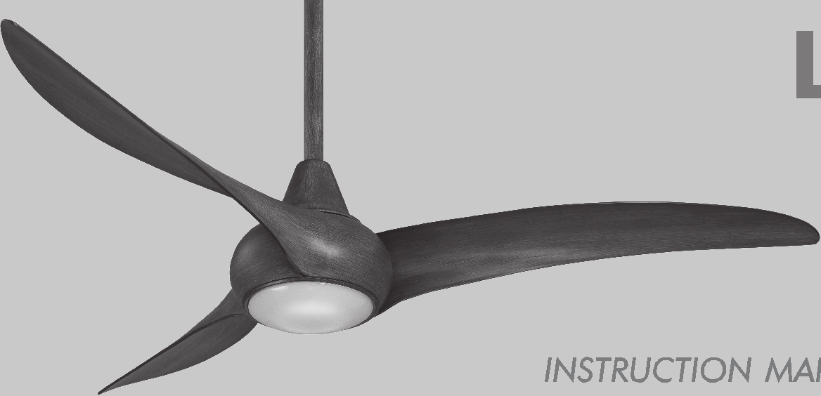
1 Light Wave CERTIFICATE
2 Manual design and all elements of manual design are protected by U.S. Federal and/or State Law, including Patent, Trademark and/or Copyright laws.
3 The Minka-Aire warranty is for one (1) year from the date of purchase from an authorized Minka-Aire dealer. This warranty is only valid to the original purchaser or user against all defects in material and workmanship ( light bulbs excluded ) for one (1) full year. Additionally, Minka-Aire warrants the motor only for the lifetime of the Minka Aire ceiling fan ( excluding wall controls and electrical components ), to the original purchaser or user. * The warranty is voided with the use of any non- Minka-Aire electrical devices, E.g., wall controls or electrical dimmer switches, etc * The warranty is void once the original purchaser or user ceases to own the fan or the fan is moved from its original point of installation. * The warranty is void with the use of any hanger bracket (non-minka Aire or non-fan specific ) other than the hanger bracket supplied & installed with this specific fan.
4 Warranty Service Information To obtain warranty service during the warranty period, the purchaser should return the fan with the sales receipt to the original place of purchase. The authorized Minka-Aire dealer, at its sole discretion, will either repair or replace the fan after verifying the legitimacy of the warranty claim. Replacement is subject to availability of the same model. If the model is unavailable it will be replaced by one of equal value. This is a limited warranty; the original purchaser or user is responsible for the cost of removal and reinstallation of repaired or replacement product. To obtain the name of the Minka-Aire authorized dealer nearest you call the Minka-Aire customer care department at , or contact Minka-Aire through and select FAQ to answer any questions or if you require additional assistance submit the question from found there. Date Purchased Store Purchased Model Number F844 Serial Number
5 CONTENTS SAFETY RULES... 1 PACKAGE CONTENTS... 2 INSTALLING THE FAN... 3 BLADE INSTALLATION... 4 HANGING THE FAN... 5 ELECTRICAL CONNECTIONS... 6 FINISHING THE INSTALLATION... 7 INSTALLING THE 17W LED ASSEMBLY... 8 OPERATING THE REMOTE CONTROL/WALL CONTROL... 9 CARE OF YOUR FAN TROUBLESHOOTING SPECIFICATIONS... 12
6 1 SAFETY RULES 1. Before you begin installing the fan, shut power off the circuit breaker of the fuse box. 2. Be cautious! Read all instructions and safety information before installing your new fan. Review accompanying assembly diagrams. 3. Make sure that all electrical connections comply with local codes, ordinance, or National Electrical Codes. Hire a qualified electrician or consult a do-it-your self wiring handbook if you are unfamiliar with installing electrical wiring. 4. Make sure the installation site you choose allows the fan blades to rotate without any obstructions. Allow a minimum clearance of 7 feet from the floor and 18 inches from the top of the blades to the wall. 5. If you are mounting the fan to a ceiling fan outlet box, use a U.L Listed metal octagonal outlet box marked"acceptable For Fan Support". Secure the box directly to the building structure. The outlet box and its support must be able to support the moving weight of the fan (at least 50 pounds). Do not use a plastic box. 6. Caution: To reduce the risk of injury use only the screws provided with the outlet box in conjunction with the lock washers provided with the fan. 7. If you are mounting the fan to a joist, make sure it is able to support the moving weight of the fan (at least 50 pounds). 8. After you install the fan, make sure that all mounting components are secured to prevent the fan from falling. 9. Do not insert anything into the fan blades while the fan is operating. 10. Turn the fan off and wait for the blades to stop completely before performing any maintenance or cleaning.
7 NOTE: The important safeguards and instructions appearing in this manual are not meant to cover all possible conditions and situations that may occur. It must be understood that common sense, caution and care are factors which can not be built into this product. These factors must be supplied by the person(s) installing, caring for and operating the unit. NOTE: READ AND SAVE ALL INSTRUCTIONS! WARNING TO REDUCE THE RISK OF FIRE,ELECTRIC SHOCK OR OTHER PERSONAL INJURY, MOUNT FAN ONLY TO A U.L LISTED OUTLET BOX OR SUPPORTING SYSTEM MARKED ACCEPTABLE FOR FAN SUPPORT AND USE MOUNTING SCREWS PROVIDED WITH THE OUTLET BOX IN CONJUCTION WITH THE LOCK WASHERS PROVIDED WITH THE FAN. MOST OUTLET BOXS COMMONLY USED FOR THE SUPPORT OF LIGHTING FIXTURES ARE NOT ACCEPTABLE FOR FAN SUPPORT AND MAY NEED TO BE REPLACED. CONSULT A QUALIFIDE ELECTRICIAN IF IN DOUBT. TO REDUCE THE RISK OF PERSONAL INJURY, DO NOT BEND THE BLADE HOLDERS WHILE INSTALLING BALANCING THE BLADES OR CLEANING THE FAN. DO NOT INSERT FOREIGN OBJECTS BETWEEN ROTATING FAN BLADES. TO REDUCE THE RISK OF FIRE OR ELECTRONIC SHOCK, THIS FAN ONLY CAN USE DL-1167RYS-02 SOLID-STATE SPEED CONTROL WITH DL-4111G-01 REMOTE CONTROL ONLY.
8 2 PACKAGE CONTENTS Unpack your fan and check the contents. You should have the following items: 1. Fan blades(3) 2. Hanger bracket 3. Canopy 4. Canopy cover 5. Standard downrod assembly (6") Minimum-length downrod (4.5") 6. Coupling cover 7. Fan motor/housing assembly 8. Flywheel 9. 17W LED assembly 10. Receiver with 6 wire nuts 11. Transmitter+holder+2 mounting screws A. Mounting hardware: #8x3/4 Machine screws (2) #10x1.5 Wood screws (2) 4mm Star washers (2) Metal washers (2) Lock washers (2) B. Blade attachment hardware: 1/4 x15.8mm screws with lock washers(10) C. Flywheel attachment hardware: 1/4 x9.5mm screws with lock washers(6) A B C
9 Tools Required: Philips screw driver, slotted screw driver, step-ladder, wire cutters, electrical tape. MOUNTING OPTIONS If there isn't an existing mounting box, then read the following instructions. Disconnect the power by removing fuses or turning off circuit breakers. Secure the outlet box directly to the building structure. Use appropriate fasteners and building materials. The outlet box and its support must be able to fully support the moving weight of the fan (at least 50 lbs.).use a UL listed metal outlet box. Do not use a plastic outlet box. Figure1,2 and 3 are examples of different ways to mount the outlet box. Note: You may need a longer downrod to maintain proper blade clearance when installing on R a steep, sloped ceiling. Longer downrods are available from your Minka-Aire dealer. To hang your fan where there is an existing fixture but no ceiling joist, you may need to R install a hanger bar as shown in Fig.4(available at your Minka Aire dealer or local hardware store). INSTALLING THE FAN CROSS BRACE CEILING joist FIG. 1 ANGLED CEILING MAXIMUM 18 ANGLE RECESSED OUTLET BOX CEILING JOIST OUTLET BOX PROVIDE STRONG SUPPORT HANGER OPENING must be FACING UPSIDE CEILING JOIST OR CROSS BRACE FIG. 2 OUTLET BOX PARALLEL WOOD BRACE (MIN. 2 THICK) HANGER BAR (OPTIONAL) OUTLET BOX CEILING JOIST HANGER BRACKET 3 FIG. 3 FIG. 4
10 4 BLADE INSTALLATION Step 1. Align the 3 holes from the blade to the fan motor. Secure blade with 3 blade screws with locked washer provided. Follow the same process for the remaining two blades. (Fig. 5) All blade sets are grouped together by weight. Fan motor Screw Flywheel Fan motor Screw Step 2. Align holes in the flywheel and the fan motor assembly, and secure with the screw. Ensure all the screws are tightened. (Fig. 6) Fig. 5 Blade Fig. 6
11 HANGING THE FAN 5 WARNING: All of the parts, hardware and components such as the hanger bracket and hanger ball have been provided for your safety and the proper installation of your new ceiling fan. The use of other R parts,hardware or components not supplied by Minka Aire with the fan R will void the Minka Aire Warranty. REMEMBER to turn off the power. Follow the steps below to hang your fan properly: Step 1.Secure the hanger bracket to the ceiling outlet box using screws and washers included with mounting hardware.(fig.7) Stpe 2.Lossen the two set screws and remove the hitch pin and lock pin from the top coupling of the motor assembly.(fig. 8) Step 3.Remove hanger ball from downrod assembly by loosening set screw,removing the cross pin, and sliding ball off rod.(fig. 9) Step 4.Carefully feed fan wires up through the downrod(fig 10). Thread the rod into the coupling, next line up holes and replace lock pin and hitch pin. Tighten set screws. Step5.Slip coupling cover, canopy cover, and canopy onto downrod (Fig.11). Carefully reinstall hanger ball onto rod being sure that cross pin is in the correct position, set screws are tighten and wires are not twisted. NOTE:DO NOT INSTALL THE COUPLING COVER IF YOU PLAN TO USE THE MINIMUM LENGTH DOWNROD. Step 6. Now lift motor assembly into position and place hanger ball into hanger bracket. Rotate until the check groove has dropped into the registration slot and seats firmly.(fig 12)Rod should not rotate if this is done correctly.
12 OUTLET BOX HITCH PIN SET SCREWS LOCK PIN HANGER BALL CROSS PIN SET SCREW DOWNROD SUPPLY WIRES DOWNROD CANOPY CANOPY COVER COUPLING COVER REGISTRATION SLOT HANGER BRACKET DOWNROD LOCK PIN SCREWS HITCH PIN Fig. 7 Fig. 8 Fig. 9 Fig. 10 Fig. 12 Fig. 11
13 WARNING:To avoid possible electrical shock be sure electricity is turned off at the main fuse or breaker box before wiring. R NOTE: The Aire Control System is equipped with a learning frequency function which has 256 code combinations to prevent potential interference from other remote units.the frequency on your Receiver and Transmitter units have been preset at the factory. (Fig.13) No frequency change is necessary, should you desire to install another fan whithin the same home or area with a separate frequency code please see the frequency interference troubleshooting section of this instruction manual to learn how to change the frequency. Step 1. Insert Receiver into Hanger Bracket with the flat side of the Receiver facing the ceiling.(fig.14) ELECTRICAL CONNECTIONS Step 2. Motor to Receiver Electrical Connections: Connect the WHITE wire from the fan to the WHITE wire marked TO MOTOR N from the Receiver. Connect the BLACK wire from the fan to the BLACK wire marked TO MOTOR L from the Receiver. Connect the BLUE wire from the fan to the BLUE wire marked For Light from the Receiver. NOTE: If your ceiling fan features an UP Light: Connect the ORANGE wire from the fan to the ORANGE wire marked For Up Light from the Receiver. Otherwise disregard this step and proceed to secure all wire connections with the plastic wire nuts provided.(fig.15) Note: Fan must be installed from a maximum distance of 40 feet from the transmitting unit for proper signal transmission between the transmitting unit and the fan s receiving unit. 6
14 Step 3.Receiver to House Supply Wires Electrical connections: Connect the WHITE wire(neutral) from the outlet box to the WHITE wire marked AC in N from the receiver. Connect the BLACK wire(hot) from the outlet box to the BLACK wire marked AC in L from the receiver. Secure all wire connections with the plastic wire nuts provided.(fig.15) Step 4.If your outlet box has a GROUND wire (Green or Bare Copper) connect this wire to the Hanger Ball and Hanger Bracket Ground wires. If your outlet box does not have a Ground Wire, then connect the Hanger Ball and Hanger Bracket Ground Wire together. Secure wire connection with the plastic wire nut provided.(fig. 15) After all splices are made, check to make sure there are no loose strands. As an additional precaution we suggest to secure the plastic wire connectors to the wires with electrical tape. Fig. 13 RECEIVER Fig. 14 HANGER BRACKET
15 OUTLET BOX BLACK (HOT) BLACK (" AC IN L ") WHITE (NEUTRAL) GREEN OR BARE COPPER (GROUND) WHITE (" AC IN N ") RECEIVER BLACK (" TO MOTOR L ") BLUE (FOR LIGHT) ORANGE (FOR UPPER LIGHT) BLUE (FOR LIGHT) BLACK (MOTOR) ORANGE (FOR UPPER LIGHT) WHITE (" TO MOTOR N ") GROUND-(CONNECT TO (GREEN) GROUND WIRE ON HANGER BRACKE IF NO HOUSE GROUND WIRE EXISTS.) WHITE (NEUTRAL) Fig. 15
16 7 FINISHING THE INSTALLATION Step 1. Tuck connections neatly into ceiling outlet box. Step 2. Remove one screw from the hanger bracket and loosen the other screw around 1/4. Step 3. Align the canopy up to ceiling and over the loose screw. Place the canopy into key hole and rotate canopy clockwise. (Figure 16) Step 4. Secure the canopy by use previous removed screw. Step 5. Place the canopy cover to the canopy and rotate canopy cover clockwise until it is locked into right position.(figure 16) OUTLET BOX HANGER BRACKET HANGER BALL CANOPY Fig. 16 CANOPY COVER
17 Step 1. While holding the 17W LED assembly under your fan, firmly snap the wire connection plugs together. (Fig.17) INSTALLING THE 17W LED ASSEMBLY 8 Step 2. Attach the 17W LED assembly to the switch box by twisting tightly.(fig.17) Note: This is a integrated LED light kit assembly and can not be disassembled to provent electronical shock. Switch box Connection plug 17W LED assembly Fig. 17
18 9 OPERATING THE REMOTE CONTROL/WALL CONTROL Remote Control only: Install a A23 12volt battery (included). To prevent damage to transmitter remove the battery if not used for long periods of time. Restore Power to Ceiling Fan. A. Buttons: These buttons are used to set the fan speeds as follows; = Low Speed = Medium Speed = High Speed B. Button: This button turns the fan off. C. Button: These buttons turn the light ON or OFF and also control the brightness settings of the light. The following instructions apply to ceiling fans that feature a DOWN light ( button) only or ceiling fans that feature an UP light ( button) and a DOWN light ( button) that are controlled independent of each other; Press and release the button for the desired light to turn the light ON or OFF. Press and hold the button to set the desired light brightness. The light will cycle between bright and dim settings as long as the button is pressed. The light key has an automatic auto-resume feature that allows the light to remain at the same brightness as the last time it was turned off. D. OFF-ON Slide Button (Wall Control Fans Only) This button turns the power Off and On to the Fan and Light(s). E. Button: (Full Function Remote Control Units Only) This button is used to change the direction of the rotation of the blades; forward for warm weather or reverse for cool weather. NOTE: If your Remote Control or Wall Control does not have a " " button, Please look for a slide reverse switch on the switch housing.
19 Speed settings for warm or cool weather depend on factors such as the room size. Ceiling height, number of fans, etc. The Reverse switch is located on the coupling. Slide the switch to the down for warm weather operation. Slide the switch to the up for cool weather operation.(fig. 18) NOTE: Wait for fan to stop before changing the setting of the slide switch. Warm Weather(forward) A DOWNWARD airflow creates a cooling effect as shown in Figure 19. This allows you to set your air conditioner on a warmer setting without affecting your comfort. Cool Weather(Reverse) An UPWARD airflow moves warmer air off the ceiling area as shown in Figure 20. This allows you to set your heating unit on a cooler setting without affecting your comfort. Warm weather Fig. 18 Reverse switch Cool weather
20 SUMMER OPERATION WINTER OPERATION Fig. 19 Fig. 20
21 Here are some suggestions to help maintain your fan. 1.Because of the fan s natural movement some connections may become loose. Check the support connections, brackets and blade attachment twice a year. Make sure they are secure.(it is not necessary to remove fan from the ceiling). 2.Clean your fan periodically to help maintain its new appearance over the years. Use only a soft brush or lint free cloth to avoid scratching the finish. Plated finishes are sealed with lacquer to minimize discoloration or tarnishing. Do not use water when cleaning, this could damage the motor, wood blades or possibly cause an electrical shock. 3.Use a lint free lightly damp cloth or duster to remove dust from the blades. CARE OF YOUR FAN 10 4.There is no need to oil your fan. The motor has permanently lubricated bearings. 5.If your fan is provided with glass shades, clean with lukewarm soapy water and a soft cloth or sponge.do NOT IMMERSE GLASS SHADES IN HOT WATER. DO NOT PUT GLASS SHADES INTO AN AUTOMATIC DISHWASHER. WARNING MAKE SURE THE POWER IS OFF AT THE ELECTRICAL PANEL BOX BEFORE YOU ATTEMPT ANY REPAIRS. REFER TO THE SECTION ELECTRICAL CONNECTIONS.
22 11 TROUBLESHOOTING SYMPTOM Fan will not start SOLUTION Check to make sure the wall switch is turned on. Check circult fuses or breakers. Caution! Make sure the power is turned off before performing the following steps. Remove canopy and check wire connections. Check wall control transmitter connections(if applicable). Note:fan must be installed at a maximum distance of 40 feet from the transmitting unit for proper signal transmission between the transmitting unit and the fan s receiving unit. SYMPTOM Fan Sounds Noisy SOLUTION Allow a 24 - hour break in period. Most noises associated with a new fan will go away during this time. Make sure the screws that attach the fan blade holder to the motor hub is tight. Make sure outlet box is secured to building structure, if necessary use the wood screws provided to fruther secure outlet box to joist. Make sure hanger bracket is secure to the outlet box,screws are tight.
23 SYMPTOM Fan Wobble SOLUTION NOTE: All blade sets are grouped by weight. Make sure outlet box is secured to building structure, if necessary use the wood screws provided to further secure outlet box to joist. Make sure hanger bracket is secure to the outlet box, screws are tight. If a Balancing kit is provided follow the instructions included with the balancing kit to help correct any excessive wobble. SYMPTOM Fans/Light Turn on and Off Unexpectedly SOLUTION This is caused by interference. Please see Freduency interference for step to charge the frequency.
24 SYMPTOM Frequency Interference SOLUTION 1.Turn the power off to your ceiling fan. 2.Please use a small size tool to change the frequency settings on the control system. 3.Returm power to the unit. Note: After the AC power is on, do not press any other button on the transmitter before pressing the Stop button, doing so will cause the procedure to fail. 4.Within 60 seconds of turning the fan s AC power ON. Press the transmitter s Stop button and hold the Stop button for 10 seconds. 5.Once the receiver has detected the set frequency, the down light of your fan will blink twice and the fan will begin to rotate for a short period and then shut off. 6.The receiver has now learn the frequency which has been selected on the transmitter. After completing the steps above, you should be able to operate the ceiling fan and light. If the fan is not responding to the transmitter. please turn the power off to the receiver, and repeat the process.
25 R SPECIFICATIONS 12 These are typical readings. Your actual fan may vary. They do not include amps and wattage used by the light (s). For any additional information about your R Minka Aire Ceiling fan, please write to:
26
SAN FRANCISCO. U.S. Patents: 5,951,253; 6,158,964; 6,171,060; 6,250,885 INSTRUCTION MANUAL WARRANTY CERTIFICATE
 SAN FRANCISCO BY U.S. Patents: 5,951,253; 6,158,964; 6,171,060; 6,250,885 INSTRUCTION MANUAL WARRANTY CERTIFICATE This product is protected by United States Federal and/or State Law, including Patent,
1. SAFETY RULES. 8. Avoid placing objects in the path of the blades.
 1 1. SAFETY RULES 1. To reduce the risk of electric shock, insure electricity has been turned off at the circuit breaker or fuse box before beginning. 2. All wiring must be in accordance with the National
Table of Contents. www.hunterfan.com. What to Expect with. Preparation. Tools Needed. Wiring. Hanging the Fan. Blades. Motor Housing.
 www.hunterfan.com Table of Contents What to Expect with Your Installation 30 inches Hanging the Fan Wiring 8 Maintenance, Operation & Cleaning Light Kit 13??? 14 1 9 Troubleshooting 11 5 Blades Motor Housing
1. SAFETY RULES WARNING TO REDUCE THE RISK OF FIRE, ELECTRIC SHOCK OR PERSONAL INJURY, MOUNT FAN TO OUTLET BOX MARKED "ACCEPTABLE FOR FAN SUPPORT".
 1 1. SAFETY RULES 1. To reduce the risk of electric shock, insure electricity has been turned off at the circuit breaker or fuse box before beginning. 2. All wiring must be in accordance with the National
Scottsdale 52 in Ceiling Fan Owne r s manual. Scottsdale Ventilador de Techo de 1,32 Manual del Propietario
 538 855 Scottsdale 52 in Ceiling Fan Owne r s manual Scottsdale Ventilador de Techo de 1,32 Manual del Propietario m Scottsdale by Hampton Bay 56 Scottsdale Thank you for purchasing our ceiling fan. This
60" TulleTM. Instruction Manual. A Kichler Select ceiling fan
 60" TulleTM A Kichler Select ceiling fan Kichler Lighting 7711 East Pleasant Valley Road P.O. Box 318010 Cleveland, Ohio 44131-8010 Customer Service 866.558.5706 8:30 AM to 5:00 PM EST, Monday - Friday
Owners & Installation Manual for the Sheridan, Mountainair, Pine Valley and Old Forge Ceiling Fan Family
 Owners & Installation Manual for the Sheridan, Mountainair, Pine Valley and Old Forge Ceiling Fan Family Part of the Kiva Lighting Family Custom Lighting and Fans Since 1992 1312 12th St NW Albuquerque,
CortezTM A Kichler Décor Ceiling Fan
 CortezTM A Kichler Décor Ceiling Fan Kichler Lighting 7711 East Pleasant Valley Road P.O. Box 318010 Cleveland, Ohio 44131-8010 Customer Service 866.558.5706 8:30 AM to 5:00 PM EST, Monday - Friday Instruction
54 LinkTM. Instruction Manual. Includes our new CoolTouch Control System Looks permanent, but goes wherever you go! U.S.
 54 LinkTM Includes our new CoolTouch Control System TM Looks permanent, but goes wherever you go! U.S. Patent Pending A Kichler Décor ceiling fan HIGH EFFICIENCY DC MOTOR Kichler Lighting 7711 East Pleasant
LUCCI AIRFUSION QUEST II CEILING FAN
 LUCCI AIRFUSION QUEST II CEILING FAN WITH IR REMOTE INSTALLATION OPERATION MAINTENANCE WARRANTY INFORMATION CAUTION READ INSTRUCTIONS CAREFULLY FOR SAFE INSTALLATION AND FAN OPERATION. V1.0 QUEST II IR
Owner s Guide and Installation Manual. Vancouver Model Name. 21321, 21328 Model No. English Español
 For Your Records and Warranty Assistance For reference, also attach your receipt or a copy of your receipt to the manual. Vancouver Model Name 21321, 21328 Model No. Type A Models Owner s Guide and Installation
Ceiling Fan Installation Instructions
 Ceiling Fan Installation Instructions 1525..series OWNER S MANUAL READ AND SAVE THESE INSTRUCTIONS Total fan wieght with light kit 1-1525-CUL-English INSTALLATION CH-545 Safety Tips WARNING: TO REDUCE
Atlanta CAUTION READ INSTRUCTIONS CAREFULLY FOR SAFE INSTALLATION AND FAN OPERATION. IF UNSURE CONSULT A QUALIFIED ELECTRICIAN
 OWNERS INSTRUCTION MANUAL 30 /76cm Atlanta INSTALLATION OPERATION MAINTENANCE CAUTION READ INSTRUCTIONS CAREFULLY FOR SAFE INSTALLATION AND FAN OPERATION. IF UNSURE CONSULT A QUALIFIED ELECTRICIAN PAGE
ChicagoTM. Instruction Manual. Includes our new CoolTouch TM Control System Looks permanent, but goes wherever you go! U.S.
 ChicagoTM A Kichler Décor ceiling fan Designed to coordinate with a popular Kichler Lighting collection. Includes our new CoolTouch TM Control System Looks permanent, but goes wherever you go! U.S. Patent
AerAtron. Ceiling fans
 AerAtron Ceiling fans User Manual & Technical Specifications Models: e502 & e503 Australian edition 2011 Instructions...3 General precautions...3 Location and installation requirements for your fan...3
AerAtron. Ceiling fans
 AerAtron Ceiling fans User Manual & Technical Specifications Models: e502 & e503 Electricians PLEASE FOLLOW THESES INSTRUCTIONS CAREFULLY & PAY SPECIAL ATTENTION TO THE NOTES NOTES WILL ASSIST WITH AN
READ AND SAVE THESE INSTRUCTIONS
 READ AND SAVE THESE INSTRUCTIONS SUMMER NIGHT 52 Damp Location Ceiling Fan Owner's Manual Net Weight: 1.5 Lbs. ENERGY STAR Model No. CF52AW01 CF52ORB01 CF52BQ01 CF52WB01 CF52CK01 CF52WW01 CF52SCB01 LIMITED
READ AND SAVE THESE INSTRUCTIONS HIGHRISE. 50 Ceiling Fan Owner's Manual. Model Numbers CF430SW00. Satin White. Net Weight: 24.3 Lbs.
 READ AND SAVE THESE INSTRUCTIONS HIGHRISE 50 Ceiling Fan Owner's Manual CF430BS00 Brushed Steel Model Numbers CF430SW00 Satin White Net Weight: 24.3 Lbs. CF430ORB00 Oil Rubbed Bronze Questions, problems,
READ AND SAVE THESE INSTRUCTIONS PORTLAND. 54 Ceiling Fan Owner's Manual
 READ AND SAVE THESE INSTRUCTIONS PORTLAND 54 Ceiling Fan Owner's Manual Model Numbers CF965BS00 - Brushed Steel CF965VNB00 - Venetian Bronze Net Weight: 25.9 Lbs. Questions, problems, missing parts: Before
LED MOTION ACTIVATED FLOOD LIGHT
 Utilitech & UT Design are registered trademarks of LF, LLC. All Rights Reserved. ITEM #0611551, #0611550 LED MOTION ACTIVATED FLOOD LIGHT MODEL #SE1036-BP2-02LF0-U, SE1036-WH3-02LF0-U Français p. 10 Español
Portable Air Conditioner. OWNER S MANUAL Read these instructions before use. Model: MM14CCS. Voltage rating: 115V~60Hz Power rating : 1400W
 Portable Air Conditioner OWNER S MANUAL Read these instructions before use Model: MM14CCS Customer Support : 1-800-474-2147 Voltage rating: 115V~60Hz Power rating : 1400W For product inquiries or support
4.3-inch Back-Up Camera
 TM 4.-inch Back-Up Camera Model No.: PKC0BU4 Owner s Manual and Warranty Information Read these instructions completely before using this product. Retain this Owner s Manual for future reference. INTRODUCTION
INSTALLATION INSTRUCTION SPEC. SHEET 7/00. City of New York Calendar #40747 ETL LISTED UNDER U.L. STD. 2108 LOW VOLTAGE TRACK LIGHTING SYSTEM
 7/00 INSTALLATION INSTRUCTION SPEC. SHEET 99052 99063 City of New York Calendar #40747 Copyright c 2000 ALFA Lighting, Inc. All rights reserved. Call:1-415-975-8080 QUICK JACK QJS R LISTED 9901483 ETL
Installation Guide A0 www.haikufan.com 2013 Delta T Corporation
 Installation Guide A0 Installation Guide: April 2013 Rev. J Model Number: K3150-A0 S3150-A0 May be protected by one or more of the following patents: Australian Registered Design No. 325331, 328015; U.S.
Cooktop Low-Profile Ventilation Hoods
 INSTALLATION GUIDE Cooktop Low-Profile Ventilation Hoods Contents Wolf Cooktop Low-Profile Ventilation Hoods........ 3 Cooktop Low-Profile Hood Specifications.......... 4 Cooktop Low-Profile Hood Installation............
Portable Air Conditioner. OWNER S MANUAL Read these instructions before use. Model: MN12CES / MN10CESWW
 Portable Air Conditioner OWNER S MANUAL Read these instructions before use 8 Model: MN12CES / MN10CESWW Voltage rating: 120V~60Hz Power rating : 1100W (MN12CES) Power rating : 900W (MN10CESWW) Customer
Roof Top Air Conditioner INSTALLATION AND OPERATING INSTRUCTIONS
 Roof Top Air Conditioner INSTALLATION AND OPERATING INSTRUCTIONS Ducted System RECORD THIS UNIT INFORMATION FOR FUTURE REFERENCE: Model Number: Serial Number: Date Purchased: This manual must be read and
Andersen Electric Window Opener for Andersen Awning and Roof Windows
 W A Electric Window Opener Electric Window Opener for Awning and Roof Windows Congratulations! You have just purchased one of the many fine products. For ease of installation and continued enjoyment of
Installation Guide X0 www.haikufan.com 2013 Delta T Corporation
 Installation Guide X0 Installation Guide: April 2013 Rev. E Model Number: K3150-X0 S3150-X0 May be protected by one or more of the following patents: Australian Registered Design No. 325331, 328015; U.S.
BUILT-IN DISHWASHER INSTALLATION INSTRUCTIONS
 BUILT-IN DISHWASHER INSTALLATION INSTRUCTIONS PLEASE READ COMPLETE INSTRUCTIONS BEFORE YOU BEGIN LEAVE INSTALLATION INSTRUCTIONS AND USER'S GUIDE WITH OWNER ALL ELECTRIC WIRING AND PLUMBING MUST BE DONE
INSTALLATION INSTRUCTIONS
 INSTALLATION INSTRUCTIONS VOLT LED Edge-Lit Flat Panel VFP-22 and VFP-24 Series Help Hotline: 1-813-978-3700 Mon-Fri 8am-8pm Sat-Sun 10am - 6pm (EST) Specifications and product details subject to change
GreenWay Solar LED Path and Trail Lighting System. Installation and Owner s Manual
 GreenWay Solar LED Path and Trail Lighting System Installation and Owner s Manual Important Notes and Warnings This installation and instruction manual provides installation, operation, and maintenance
Basic Spring Motor Roller Shades
 Comprehensive Roller Shade Installation Guide Basic Spring Motor Roller Shades ATTENTION!!! READ CAREFULLY! This shade has a reliable long-lasting Spring Motor. The Spring Motor must have proper tension
Portable Air Conditioner. OWNER S MANUAL Read these instructions before use. Model: MF08CESWW. Voltage rating: 115V~60Hz Power rating : 800W
 MODE ALARM Portable Air Conditioner OWNER S MANUAL Read these instructions before use 8 Model: MF08CESWW Voltage rating: 115V~60Hz Power rating : 800W Customer Support : 1-800-474-2147 For product inquiries
LED Security Spotlight User Manual
 MOT ION-TR ACKING LED Security Spotlight User Manual www.jascoproducts.com 1-800-654-8483 2 TABLE OF CONTENTS Parts List 3 Questions? Missing Parts? 4 Installation (Wall mount) 6-9 Installation (Eave mount)
Tablet 30W Tablet 92W
 Tablet 30W Tablet 92W Owner s Manual 1 CONTENTS TABLE OF CONTENTS Important Safety Instructions 3-4 Parts Exploded View & Identification Tablet 30 5 Tablet 92 6 Introduction Tablet 30 7-8 Tablet 92 9-10
OPL BASIC. Dosing System for Professional Laundry machines. Contents
 OPL BASIC Dosing System for Professional Laundry machines Contents 1 Getting Started. Page 2 2 Installation. Page 4 3 Set Up & Operation. Page 8 4 Maintenance & Accessories. Page 10 5 Troubleshooting Page
LED MOTION ACTIVATED FLOOD LIGHT
 Utilitech & UT Design are registered trademarks of LF, LLC. All Rights Reserved. ITEM #0460794, 0459228 LED MOTION ACTIVATED FLOOD LIGHT MODEL #SE1019-WH3-02LF0-U, SE1019-TBZ-02LF0-U Français p. 8 Español
Operating Instructions
 Operating Instructions Series L 000 Cord Reels Model Numbers: L 000 L 0 0 L 0 B L 0 X L 00 L A X L 0 L 0 0 L 00 L 0 L 0 B L 0 0 X L 00 L 0 A L 0 X IMPORTANT Read this manual carefully before installing,
IMPORTANT SAFETY INSTRUCTIONS WARNING READ AND SAVE THESE OPERATING AND SAFETY INSTRUCTIONS BEFORE USING THIS HEATER.
 THERMAWAVE CERAMIC HEATER Model HZ-850 Series Model HZ-860 Series IMPORTANT SAFETY INSTRUCTIONS WARNING READ AND SAVE THESE OPERATING AND SAFETY INSTRUCTIONS BEFORE USING THIS HEATER. Warning Failure to
Networkfleet 3500 Product Line Installation Guide
 Networkfleet 3500 Product Line Installation Guide Light/Medium Duty (L3500) Heavy Duty (H3500) Universal (U3500) www.networkcar.com/fleet Customer Care: (866) 227-7323 customercare@networkcar.com Table
UB1 AIR CONDITIONING UNIT INSTALLATION INSTRUCTIONS
 UB1 AIR CONDITIONING UNIT INSTALLATION INSTRUCTIONS INSTALLATION INSTRUCTIONS: Carefully read these instructions before installing your new air-conditioner. AUSTRALIAN AUTOMOTIVE AIR AL00500054E 1 Table
Installation Manual. Features SMART SWITCH OCCUPANCY SENSOR. Maximum Energy savings
 Features SMART SWITCH OCCUPANCY SENSOR Installation Manual Maximum Energy savings Sensitive 180º view passive infrared motion detector keeps lights on only when rooms are in use. No ON switch so lights
Pet hair clipper. Model 96822. Diagrams within this manual may not be drawn proportionally.
 Pet hair clipper Model 96822 Cleaning And Operation Instructions Diagrams within this manual may not be drawn proportionally. Due to continuing improvements, actual product may differ slightly from the
BATHROOM HEATER. User's Manual. Page 2...A515 Page 9...A716
 BATHROOM HEATER User's Manual Page 2...A515 Page 9...A716 BATHROOM HEATER User's Manual A515 SAVE THESE INSTRUCTIONS AND READ ALL INSTRUCTIONS BEFORE USING THE HEATER. Dear customers, Thank you for selecting
ATS Overhead Table Shelf System INSTRUCTION MANUAL
 ATS Overhead Table Shelf System INSTRUCTION MANUAL ATS Overhead Table Shelf System Instruction Manual Warranty Newport Corporation warrants this product to be free of defects in material and workmanship
Installation & Maintenance Instructions
 (400mm) 15-3/4" (35mm) 1-3/8" (95mm) 3-3/4" K Series (Model A) Fan Forced Wall Heaters (485mm) 19-1/8" (463mm) 18-1/4" FILE #E21609 Installation & Maintenance Instructions Dear Owner, Congratulations Thank
USER MANUAL. Bottom Loading Bottled Water Dispenser SAVE THIS MANUAL FOR FUTURE USE. Model # 900172
 Model # 900172: Page 1 USER MANUAL Bottom Loading Bottled Water Dispenser Model # 900172 TO REDUCE THE RISK OF INJURY AND PROPERTY DAMAGE, USER MUST READ THIS MANUAL BEFORE ASSEMBLING, INSTALLING & OPERATING
Portable Air Conditioner
 Portable Air Conditioner Owner's Manual Model:3 in 1 12,000 Btu/h Series 3 Please read this owner s manual carefully before operation and retain it for future reference. CONTENTS 1. SUMMARY...1 2. PORTABLE
Multi-Pitch Pitching Machine USER MANUAL
 Multi-Pitch Pitching Machine USER MANUAL TABLE OF CONTENTS Thank you for purchasing the Cimarron Multi-Pitch Pitching Machine. The Cimarron Multi-Pitch Pitching Machine is a high performance pitching machine
Ducoterra Radiant Heating Panel Installation Manual
 Ducoterra Radiant Heating Panel Installation Manual 1. Introduction Your new radiant heating panels are designed to heat living and working spaces rapidly and efficiently by radiant heating. Like the sun,
User Manual. Instructions for installing the Sure Stitch on the Next Generation Quilting Frame. Parts Included:
 User Manual Instructions for installing the Sure Stitch on the Next Generation Quilting Frame. Parts Included: 1: Display Console 1: Control Box 2: Encoder (Wires attached) (Not Shown) 1: 5v Power Supply
Wiper Motor Marinco 2.5. Installation Instructions
 Wiper Motor Marinco 2.5 Installation Instructions Wiper Motor Marinco-2.5 The Marinco 2.5 Wiper Motor Offers the Following Features: Fully sealed base and housing which allows installation in outdoor wet
Installation Instructions
 520 Installation Instructions Thank you very much for purchasing PIAA product. Please read this entire manual before installation and use of this product. For Installers Please give this Installation Manual
OWNER S MANUAL Table Tennis Table Patent Pending
 OWNER S MANUAL Table Tennis Table Patent Pending Be sure to write your model number and serial number here for future reference. You can find these numbers printed on the bottom of the table. MODEL # T8179
Control Box Wiring For PRSstandard Tool
 888-680-4466 ShopBotTools.com Control Box Wiring For PRSstandard Tool Copyright 2016 ShopBot Tools, Inc. page 1 Copyright 2016 ShopBot Tools, Inc. page 2 Table of Contents Introduction:...5 Installation:...5
Model 2300DR Installation Guide
 Model 2300DR Installation Guide POWER ACCESS CORPORATION P.O. BOX 1050 170 MAIN STREET NEW HARTFORD, CT 06057 800-344-0088 WEBSITE: www.power-access.com EMAIL: salesinfo@power-access.com 1 STANDARD PARTS
3 IN 1 BATHROOM HEATER
 3 IN 1 BATHROOM HEATER MODEL NO.: A515 - SH MINI FUNCTION: HEATER, EXHAUST FAN AND LIGHT Dear customers, Thank you for selecting the AUPU 3 in 1 Bathroom Heater. Please read all instructions before commencing
JANUS INTERNATIONAL CORPORATION INSTALLATION INSTRUCTIONS Pantheon Mini Operator
 JANUS INTERNATIONAL CORPORATION INSTALLATION INSTRUCTIONS Pantheon Mini Operator The Janus Pantheon mini operator does not typically require the provision of any additional site requirements other than
GPS AutoSteer System Installation Manual
 GPS AutoSteer System Installation Manual Supported Vehicles John Deere Sprayers 4720 4630 4730 4830 AutoTrac Ready PN: 602-0227-01-A LEGAL DISCLAIMER Note: Read and follow ALL instructions in this manual
Installation Instructions For Slider Casement Air Conditioners
 Installation Instructions For Slider Casement Air Conditioners NOTE: These instructions describe installation in a typical wood framed window with a wood SLIDE-BY sash, or installation in a metal CASEMENT
2&3 SECTION LOFT LADDER
 TWIST CATCH ASSEMBLY A4 A2 A1 A3 A7 A6 A5 2&3 SECTION LOFT LADDER Images feature the 3 section loft ladder, but the same instructions apply to both 2 & 3 section ladders Installation and Operating Instructions
DTM04 TANK MONITOR DTM08 TANK MONITOR Dtm12 TANK MONITOR. Installation and Operation Manual
 DTM04 TANK MONITOR DTM08 TANK MONITOR Dtm12 TANK MONITOR Installation and Operation Manual 1 ENGLISH Safety Instructions 2 Features 2-3 Specifications 3 Installation 4-5 Wiring Diagrams 6-7 Warranty 8
GENUINE PARTS INSTALLATION INSTRUCTIONS
 GENUINE PARTS INSTALLATION INSTRUCTIONS DESCRIPTION: Illuminated Kick Plate APPLICATION: Rogue (2011) PART NUMBER: 999G6 GX010 KIT CONTENTS: Item A B C G H QTY 1 1 1 D 1 E 1 F 3 15 6 Description Kick Plate,
Speed-Mat Rectangle Cutter
 Speed-Mat Rectangle Cutter 1 Honeycomb baseboard. 2 Left hold down. 14 3 Bottom hold down. 4 4 Left / right rule. 8 5 8 5 Left / right rule pointer. 1 6 Top / bottom rule. 7 Top / bottom rule pointer.
Electric Meat Grinder
 Electric Meat Grinder OWNER S MANUAL WARNING: Read carefully and understand all INSTRUCTIONS before operating. Failure to follow the safety rules and other basic safety precautions may result in serious
OWNER S MANUAL. Permolock C3. Docking system for Power wheelchair in vehicle
 OWNER S MANUAL US Permolock C3 Docking system for Power wheelchair in vehicle How to contact Permobil Head Office of the Permobil group Permolock C3 Docking system for electric wheelchair in vehicle Produced
BBWX1 Satellite Weather Receiver. Installation and Maintenance Guide
 BBWX1 Satellite Weather Receiver Installation and Maintenance Guide Rev FUSA 15JUL2007 Table of Contents Safety Precautions 3 Disclaimer. 3 Contents of Package. 4 Tools Required..4 Installation General
LiteAide OWNER'S MANUAL PREASSEMBLED AUTOMATIC SECURITY FLOODLIGHTS MOTION SENSOR SECURITY LIGHTING SYSTEMS
 OWNER'S MANUAL PREASSEMBLED AUTOMATIC SECURITY FLOODLIGHTS MOTION SENSOR SECURITY LIGHTING SYSTEMS LiteAide HE-100B HE-100BW HE-112 HE-112W HE-117 HE-117W HE-117-2B OWNER'S MANUAL FLOOD LAMPS (BULBS) Your
Wall-Mounting your HP computer. User Guide
 Wall-Mounting your HP computer User Guide The only warranties for Hewlett-Packard products and services are set forth in the express statements accompanying such products and services. Nothing herein should
GNOME PELLET E.I. Pellet Heater Owner's Manual Installation and Operating Instructions. Please read this entire manual before installation.
 Pellet Heater Owner's Manual Installation and Operating Instructions Please read this entire manual before installation. Save these instructions. SAFETY NOTICE HEATER MUST BE PROPERLY INSTALLED AND MAINTAINED
INFRARED QUARTZ WALL HEATER
 INFRARED QUARTZ WALL HEATER MODEL NO: IQ2000 PART NO: 6939004 MOUNTING & OPERATION INSTRUCTIONS GC0715 INTRODUCTION Thank you for purchasing this CLARKE Infrared Wall Heater. Before attempting to use this
Operation Manual. 150 Watt Halogen Light Source for Endoscopy Model # s ESS-150, ESS-150A ESS-220, ESS-220A
 Operation Manual 150 Watt Halogen Light Source for Endoscopy Model # s ESS-150, ESS-150A ESS-220, ESS-220A Endoscopy Support Services, Inc. Croton River Executive Park Route 22, Bldg. 3 Brewster, NY 10509
Installation Instructions
 Installation Instructions SELECTRONIC DC POWERED PROXIMITY EXPOSED TOILET FLUSH VALVE.,.8,.,./. &.8/. GPF Certified to comply with ASME A.9. 0 AS America, Inc. Exposed Flushometer for -/" Top Spud Bowls
R O A D M A S T E R, I N C.
 R O A D M A S T E R, I N C. ROADMASTER, Inc. 6110 NE 127th Ave. Vancouver, WA 98682 4 MOUNTING BRACKET KIT 1 2 3 360-896-0407 fax 360-735-9300 www.roadmasterinc.com ITEM QTY NAME PART # 1...2... #10 x
Owner s Manual Read and keep this manual. Patents World Wide
 Owner s Manual Read and keep this manual. Patents World Wide S & S Industries, Inc., Sarasota, FL, USA www.trail-gator.com Copyright 2008 All Rights Reserved The following manual is provided to assist
Triple Threat 3-in-1 Game Table 3 IN 1 GAME TABLE
 NG0M Triple Threat 3-in- Game Table 3 IN GAME TABLE Thank 3 in Y Game Table Thank you for your purchase of our product. We work around the clock and around the globe to ensure that our products maintain
Overview PARTS LIST. B. Lever mounting base C. Flush handle assembly D. Grey/Blue float stop E. Grey float (Full Flush) F. Flush valve washer
 F. Flush valve washer") Overview READ ENTIRE INSTRUCTIONS BEFORE STARTING INSTALLATION PARTS LIST A. Flush valve B. Lever mounting base C. Flush handle assembly D. Grey/Blue float stop E. Grey float (Full Flush) F. Flush valve
Overview READ ENTIRE INSTRUCTIONS BEFORE STARTING INSTALLATION PARTS LIST A. Flush valve B. Lever mounting base C. Flush handle assembly D. Grey/Blue float stop E. Grey float (Full Flush) F. Flush valve
TABLE OF CONTENTS. I. TROUBLESHOOTING... 2 - Section 1.01: Common Problems/Solutions... 2
 BAL Accu-Slide System I. Table of Contents TABLE OF CONTENTS I. TROUBLESHOOTING... 2 - Section 1.01: Common Problems/Solutions... 2 II. GETTING STARTED... 5 - Section 2.01: Tools You Will Need... 5 - Section
1000-LB. TRAILER JACK OWNER S MANUAL
 1000-LB. TRAILER JACK OWNER S MANUAL WARNING: Read carefully and understand all INSTRUCTIONS before operating. Failure to follow the safety rules and other basic safety precautions may result in serious
Awning Instructions. Full Cassette 1.5m to 6m
 Awning Instructions Full Cassette 1.5m to 6m English Full Cassette Manual & Electric Instructions Contents Warning 1.5m - 3.5m Awnings 8 x Expansion bolts ** 2 x brackets 1 x Awning 1 x Winder 4.0m -
Installation Instructions
 READ BEFORE INSTALLING UNIT For Slider Casement Air Conditioners To avoid risk of personal injury, property damage, or product damage due to the weight of this device and sharp edges that may be exposed:
Wireless Indoor/ Outdoor Thermometer
 Wireless Indoor/ Outdoor Thermometer Owner s Manual Please read before using this equipment. ˆ Contents FCC Information... 3 FCC Declaration of Conformity... 5 Preparation... 5 Installing Batteries...
758 Heavy-duty Ratchet Guy Wire Cutter
 INSTRUCTION MANUAL 758 Heavy-duty Ratchet Guy Wire Cutter Read and understand all of the instructions and safety information in this manual before operating or servicing this tool. Register this product
PGL5/6 - Parking Garage Luminaire Installation Instructions
 P.O. Box 60080 16555 East Gale Ave. City of Industry, California 91716-0080 626/968-5666 FAX 626/330-3861 PGL5/6 - Parking Garage Luminaire Installation Instructions PGL51/61 PGL52/62 PGL53/63 PGL54/64
Part Name/Description Part Number Quantity. Power Cable 4000950-5 1
 Note: Indented items indicate parts included in an assembly listed above Part Name/Description Part Number Quantity Power Cable 4000950-5 1 Raven Harness Adapter Kit 4100525 1 Installation Instructions
R O A D M A S T E R, I N C.
 R O A D M A S T E R, I N C. ROADMASTER, Inc. 6110 NE 127th Ave. Vancouver, WA 98682 6 13 11 MOUNTING BRACKET KIT Cable Tab 14 12 7 15 9 Cable Tab 360-896-0407 fax 360-735-9300 www.roadmasterinc.com ITEM
Select Radiators Installation Guide
 Select Radiators Installation Guide Table of Contents Informational Symbols...3 Before You Begin...4 Select Rough-In... 5 Connection Installation...6 Optional Piping Arrangements...7 Conventional Wall
FIXTURE INSTALLATION GUIDE Model T21T (Low Voltage Pendant Set 120V)
") FIXTURE INSTALLATION GUIDE Model T21T (Low Voltage Pendant Set 120V) 21T, Rev.4 6-13 IMPORTANT: Before proceeding, retrieve the GLASS SHADE INSTALLATION GUIDE, which is included with the pendant cord set
FIXTURE INSTALLATION GUIDE Model T21T (Low Voltage Pendant Set 120V) 21T, Rev.4 6-13 IMPORTANT: Before proceeding, retrieve the GLASS SHADE INSTALLATION GUIDE, which is included with the pendant cord set
ALL WEATHER W-SERIES QUARTZ TUBE ELECTRIC INFRARED RADIANT HEATER INSTALLATION USE & CARE MANUAL
 ALL WEATHER W-SERIES QUARTZ TUBE ELECTRIC INFRARED RADIANT HEATER TABLE OF CONTENTS: INSTALLATION USE & CARE MANUAL IMPORTANT INFORMATION Assembly Instructions 2 Wiring Instructions 2 Outdoor Installation
Elo Touch Solutions Wall-mounting Kit for the 5501L IDS Touchmonitors
 Installation Manual Elo Touch Solutions Wall-mounting Kit for the 5501L IDS Touchmonitors SW602206 Rev B Table of Contents Chapter 1: Safety Warning... 3 Chapter 2: Kit Contents... 4 Included in Kit...
Safety, Operation and Maintenance Manual with Parts List
 Safety, Operation and Maintenance Manual with Parts List 20-Gallon Wet/Dry Vac Important Information and Safety Instructions PLEASE READ BEFORE USE! # 961130020 9/10-Rev 1 20-Gallon Wet/Dray Vac TABLE
Assembly and Usage Instructions
 Assembly and Usage Instructions A Product 5885 West Van Horn Tavern Road Columbia, MO 65203 www.caldwellshooting.com Instruction #1001667 Limited Warranty Every Caldwell product is warrantied to be free
2 Mega-Pixel PoE Plus Speed Dome Internet Camera ICA-HM620. Quick Installation Guide
 2 Mega-Pixel PoE Plus Speed Dome Internet Camera ICA-HM620 Quick Installation Guide Table of Contents Verify The Contents Inside Package Box... 3 Physical Installation... 4 Further Configuration...12 Verify
NewAir AC-10000E, AC-10000H Portable Air Conditioner Owner s Manual PLEASE READ AND SAVE THESE INSTRUCTIONS
 NewAir AC-10000E, AC-10000H Portable Air Conditioner Owner s Manual PLEASE READ AND SAVE THESE INSTRUCTIONS BEFORE USE GENERAL SAFETY INSTRUCTIONS: ALWAYS OPERATE THE UNIT IN AN UPRIGHT POSITION AND PLACE
INSTALLATION USE & CARE MANUAL ALL WEATHER SL-SERIES QUARTZ TUBE ELECTRIC INFRARED RADIANT HEATER
 INSTALLATION USE & CARE MANUAL ALL WEATHER SL-SERIES QUARTZ TUBE ELECTRIC INFRARED RADIANT HEATER TABLE OF CONTENTS IMPORTANT INFORMATION Warnings 2 Installation Instructions 3 Wiring Instructions 3 Outdoor
Name of Equipment Silver King Model SKMCD1P/C1. This equipment chapter is to be inserted in the appropriate section of the Equipment Manual.
 Name of Equipment Silver King Model SKMCD1P/C1 This equipment chapter is to be inserted in the appropriate section of the Equipment Manual. Manufactured exclusively for McDonald s By Silver King Refrigeration,
MCR1900 Media Converter 19-Slot Chassis
 MCR1900 Media Converter 19-Slot Chassis Installation Guide Part #5500304-11 Copyright Statement This document must not be reproduced in any way whatsoever, either printed or electronically, without the
Operating Manual Color Changing Fountains
 Operating Manual Color Changing Fountains 1-877-80-PONDS www.atlanticwatergardens.com Introduction Thank you for purchasing Atlantic s Color Changing Fountains overflowing features that glow from within.