Features. Operating Voltage: 5V Input Voltage (recommended): 7-12V Input Voltage (limits): 6-20V
|
|
|
- Lesley Bailey
- 7 years ago
- Views:
Transcription
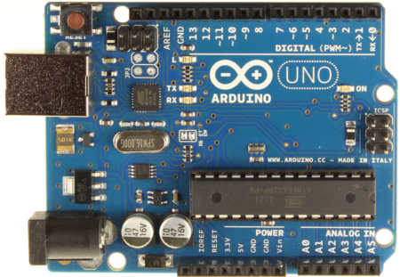
1 ARDUINO UNO
2 Features Microcontroller: ATmega328 Operating Voltage: 5V Input Voltage (recommended): 7-12V Input Voltage (limits): 6-20V Digital I/O Pins: 14 (of which 6 provide PWM output) Analog Input Pins: 6 DC Current per I/O Pin: 40 ma DC Current for 3.3V Pin: 50 ma Flash Memory 32 KB (ATmega328) of which 0.5 KB used by bootloader SRAM: 2 KB (ATmega328) EEPROM: 1 KB (ATmega328) Clock Speed: 16 MHz
3 Digital I/O Digital pins on an Arduino board can be used for general purpose I/O via pinmode, digitalread and digitalwrite functions. Arduino (Atmega) pins are by default inputs, so they don't need to be explicitly declared as inputs with pinmode. Pins configured as inputs are said to be in a high-impedance state. One way of explaining this is that input pins make extremely small demands on the circuit that they are sampling, say equivalent to a series resistor of 100 megohm in front of the pin.
4 Digital I/O Often it is useful to steer an input pin to a known state if no input is present. This can be done by adding a pullup resistor (to +5V), or a pulldown resistor (resistor to ground) on the input, with 10K being a common value. There are also convenient 20K pullup resistors built into the Atmega chip that can be accessed from software. These built-in pullup resistors are accessed in the following manner. pinmode(pin, INPUT); // set pin to input digitalwrite(pin, HIGH); // turn on pullup resistors
5 Digital I/O Pins configured as OUTPUT with pinmode are said to be in a low-impedance state. This means that they can provide a substantial amount of current to other circuits. Atmega pins can source (provide positive current) or sink (provide negative current) up to 40 ma (milliamps) of current to other devices/circuits. This is enough current to brightly light up a LED (don't forget the series resistor), or run many sensors, for example, but not enough current to run most relays, solenoids, or motors.
6 Digital I/O Digital pins on Arduino have also specific functionalities: Pin 0 (RX) and 1 (TX) can be used to receive (RX) and transmit (TX) TTL serial data. These pins are connected to the corresponding pins of the ATmega8U2 USB-to-TTL Serial chip. Pin 2 and 3 can be configured to trigger an interrupt on a LOW value, a rising or falling edge, or a change in value. See the attachinterrupt function for details.
7 Digital I/O Pin 3, 5, 6, 9, 10, and 11 can provide 8-bit PWM output through analogwrite function. They are marked in the board with the symbol ~. Pin 10 (SS), 11 (MOSI), 12 (MISO) and 13 (SCK) support SPI communication, which, although provided by the underlying hardware, is not currently included in the Arduino language. Pin 13 is connected to a built-in LED. When the pin value is HIGH (/LOW), the LED is ON (/OFF).
8 Analog Input The analog input pins support 10-bit analog-to-digital conversion (ADC) using the analogread function. In this board the analog pins can also be used as digital pins: analog input 0 as digital pin 14, analog input 1 as digital pin 15, and so on through analog input 5 as digital pin 19. Analog pin 4 (SDA) and 5 (SCL) support I 2 C (TWI) communication using the Wire library.
9 The board
10 Arduino UNO Basic Reference Source:
11 Program Structure #include... // vars declaration void setup() { // initialization instructions } void loop() { } // main program
12 I/O: pinmode pinmode function, configures the specified pin to behave either as an input or an output. As of Arduino 1.0.1, it is possible to enable the internal pullup resistors with the mode INPUT_PULLUP. Additionally, the INPUT mode explicitly disables the internal pullups.
13 I/O: pinmode pinmode(pin, mode) Params: pin: the number of the pin whose mode you wish to set. mode: n INPUT n OUTPUT n INPUT_PULLUP Returns: Nothing
14 I/O: digitalread Reads the value from a specified digital pin, either HIGH or LOW. Note that if the pin isn't connected to anything, digitalread can return either HIGH or LOW (and this can change randomly).
15 I/O: digitalread digitalread(pin) Params: pin: the number of the pin whose value you wish to read. Returns: HIGH LOW
16 I/O: digitalwrite Write a HIGH or a LOW value to a digital pin. If the pin has been configured as an OUTPUT with pinmode, its voltage will be set to the corresponding value: 5V (or 3.3V on 3.3V boards) for HIGH, 0V (ground) for LOW. If the pin is configured as an INPUT, writing a HIGH value with digitalwrite will enable an internal 20K pullup resistor. Writing LOW will disable the pullup.
17 I/O: digitalwrite digitalwrite(pin, value) Params: pin: the number of the pin whose value you wish to write. value: the value to set HIGH or LOW. Returns: Nothing
18 Example 1 // Sets pin 13 to the same value as pin 7, // declared as an input. int ledpin = 13; // LED connected to pin 13 int inpin = 7; // pushbutton connected to digital pin 7 int val = 0; // variable to store the read value void setup() { pinmode(ledpin, OUTPUT); // sets the pin 13 as output pinmode(inpin, INPUT); // sets the pin 7 as input }
19 Example 1 void loop() { val = digitalread(inpin); // read the input pin digitalwrite(ledpin, val); // sets the LED to the // button's value }
20 I/O: analogread Reads the value from the specified analog pin. The Arduino board contains a 6 channel (8 channels on the Mini and Nano, 16 on the Mega), 10-bit analog to digital converter. This means that it will map input voltages between 0 and 5 volts into integer values between 0 and This yields a resolution between readings of: 5 volts / 1024 units or,.0049 volts (4.9 mv) per unit. It takes about 100 microseconds ( s) to read an analog input, so the maximum reading rate is about 10,000 times a second.
21 I/O: analogread analogread(pin) Params: pin: the number of the analog input pin to read (from 0 to 5) Returns: int (0 to 1023)
22 I/O: analogwrite Writes an analog value (PWM wave) to a pin. Can be used to light a LED at varying brightnesses or drive a motor at various speeds. After a call to analogwrite, the pin will generate a steady square wave of the specified duty cycle until the next call to analogwrite (or a call to digitalread or digitalwrite on the same pin). The frequency of the PWM signal is approximately 490 Hz. You do not need to call pinmode to set the pin as an output before calling analogwrite.
23 I/O: analogwrite analogwrite(pin, value) Params: pin: the number of the pin whose value you wish to write. value: the duty cycle which is between 0 (always off) and 255 (always on). Returns: Nothing
24 I/O: analogwrite - PWM Pulse Width Modulation, or PWM, is a technique for getting analog results with digital means. Digital control is used to create a square wave, a signal switched between on and off. This on-off pattern can simulate voltages in between full on (5 Volts) and off (0 Volts) by changing the portion of the time the signal spends on versus the time that the signal spends off. The duration of "on time" is called the pulse width.

25 I/O: analogwrite - PWM In this graphic, the green lines represent a regular time period. This duration or period is the inverse of the PWM frequency. In other words, with Arduino's PWM frequency at about 500Hz, the green lines would measure 2 milliseconds each.
26 Example 2 // This example shows how to fade an LED using the // analogwrite() function. int ledpin = 9; // LED connected to digital pin 9 void setup() { } // nothing happens in setup void loop() { // fade in from min to max in increments of 5 points: for(int fadevalue=0;fadevalue<=255;fadevalue+=5){ // sets the value (range from 0 to 255): analogwrite(ledpin, fadevalue); // wait for 30 milliseconds to see the dimming effect delay(30); }
27 Example 2 // fade out from max to min in increments of 5 points: for(int fadevalue=255;fadevalue>=0;fadevalue-=5){ // sets the value (range from 0 to 255): analogwrite(ledpin, fadevalue); // wait for 30 milliseconds to see the dimming effect delay(30); } }
28 Advanced I/O: tone Generates a square wave of the specified frequency (and 50% duty cycle) on a pin. A duration can be specified, otherwise the wave continues until a call to notone. The pin can be connected to a piezo buzzer or other speaker to play tones. Only one tone can be generated at a time. If a tone is already playing on a different pin, the call to tone() will have no effect. If the tone is playing on the same pin, the call will set its frequency.
29 Advanced I/O: tone Use of the tone function will interfere with PWM output on pins 3 and 11 (on boards other than the Mega). Note that it is not possible to generate tones lower than 31Hz and if you want to play different pitches on multiple pins, you need to call notone on one pin before calling tone on the next pin.
30 Advanced I/O: tone tone(pin, frequency) tone(pin, frequency, duration) Params: pin: the pin on which to generate the tone. frequency: the frequency of the tone in hertz - unsigned int. duration: (optional) the duration of the tone in milliseconds - unsigned long Returns: Nothing
31 Advanced I/O: notone Stops the generation of a square wave triggered by tone. Has no effect if no tone is being generated. Note that if you want to play different pitches on multiple pins, you need to call notone on one pin before calling tone on the next pin.
32 Advanced I/O: notone notone(pin) Params: pin: the pin on which to stop generating the tone. Returns: Nothing
33 Time: delay Pauses the program for the amount of time (in miliseconds) specified as parameter. delay(ms) Params: ms: the number of milliseconds to pause (unsigned long). Returns: Nothing
34 Serial Used for communication between the Arduino board and a computer or other devices. All Arduino boards have at least one serial port (also known as a UART or USART): Serial. It communicates on digital pins 0 (RX) and 1 (TX) as well as with the computer via USB. Thus, if you use these functions, you cannot also use pins 0 and 1 for digital input or output.
35 Serial You can use the Arduino environment's built-in serial monitor to communicate with an Arduino board. Click the serial monitor button in the toolbar and select the same baud rate used in the call to begin.
36 Serial: Serial.begin Sets the data rate in bits per second (baud) for serial data transmission. For communicating with the computer, use one of these rates: 300, 600, 1200, 2400, 4800, 9600, 14400, 19200, 28800, 38400, 57600, or You can, however, specify other rates - for example, to communicate over pins 0 and 1 with a component that requires a particular baud rate. An optional second argument configures the data, parity, and stop bits. The default is 8 data bits, no parity, one stop bit.
37 Serial: Serial.begin Serial.begin(speed) Serial.begin(speed, config) Params: speed: in bits per second (baud) - long config: (optional) sets data, parity, and stop bits. Valid values are: n SERIAL_5N1 n SERIAL_6N1 n SERIAL_7N1 n SERIAL_8N1 (the default)
38 Serial: Serial.begin n SERIAL_5N2 n SERIAL_6N2 n SERIAL_7N2 n SERIAL_8N2 n SERIAL_5E1 n SERIAL_6E1 n SERIAL_7E1 n SERIAL_8E1 n SERIAL_5E2 n SERIAL_6E2 n SERIAL_7E2 n SERIAL_8E2 n SERIAL_5O1 n SERIAL_6O1 n SERIAL_7O1 n SERIAL_8O1 n SERIAL_5O2 n SERIAL_6O2 n SERIAL_7O2 n SERIAL_8O2 Returns: Nothing
39 Serial: Serial.available Get the number of bytes (characters) available for reading from the serial port. This is data that's already arrived and stored in the serial receive buffer (which holds 64 bytes). Serial.available() Params: None Returns: The number of bytes available to read
40 Serial: Serial.read Reads incoming serial data. Serial.read() Params: None Returns: The first byte of incoming serial data available (or -1 if no data is available) int
41 Serial: Serial.write Writes binary data to the serial port. This data is sent as a byte or series of bytes. To send the characters representing the digits of a number use the print function instead.
42 Serial: Serial.write Serial.write(val) Serial.write(str) Serial.write(buf, len) Params: val: a value to send as a single byte str: a string to send as a series of bytes buf: an array to send as a series of bytes len: the length of the buffer Returns: the number of bytes written
43 Serial: Serial.print Prints data to the serial port as human-readable ASCII text. This command can take many forms. Numbers are printed using an ASCII character for each digit. Floats are similarly printed as ASCII digits, defaulting to two decimal places. Bytes are sent as a single character. Characters and strings are sent as is. For example: Serial.print(78); // gives "78" Serial.print( ); // gives "1.23" Serial.print('N'); // gives "N" Serial.print("Hello world."); // gives "Hello world."
44 Serial: Serial.print An optional second parameter specifies the base (format) to use; permitted values are BIN (binary, or base 2), OCT (octal, or base 8), DEC (decimal, or base 10), HEX (hexadecimal, or base 16). For floating point numbers, this parameter specifies the number of decimal places to use. For example: Serial.print(78, BIN); // gives " " Serial.print(78, OCT); // gives "116" Serial.print(78, DEC); // gives "78" Serial.print(78, HEX); // gives "4E" Serial.print( , 0); // gives "1" Serial.print( , 4); // gives "1.2346"
45 Serial: Serial.print Serial.print(val) Serial.print(val, format) Params: val: the value to print - any data type. format: specifies the number base (for integral data types) or number of decimal places (for floating point types). Returns: the number of bytes written - size_t (long).
46 Serial: Serial.println Prints data to the serial port as human-readable ASCII text followed by a carriage return character (ASCII 13, or '\r') and a newline character (ASCII 10, or '\n'). This command takes the same forms as Serial.print.
47 Serial: Serial.println Serial.println(val) Serial.println(val, format) Params: val: the value to print - any data type. format: specifies the number base (for integral data types) or number of decimal places (for floating point types). Returns: the number of bytes written - size_t (long).
48 SoftwareSerial The Arduino hardware has built-in support for serial communication on pins 0 and 1 (which also goes to the computer via the USB connection). The native serial support happens via a piece of hardware (built into the chip) called a UART. This hardware allows the Atmega chip to receive serial communication even while working on other tasks, as long as there room in the 64 byte serial buffer.
49 SoftwareSerial The SoftwareSerial library has been developed to allow serial communication on other digital pins of the Arduino, using software to replicate the functionality (hence the name "SoftwareSerial"). It is possible to have multiple software serial ports with speeds up to bps. A parameter enables inverted signaling for devices which require that protocol.
50 SoftwareSerial The SoftwareSerial library has been developed to allow serial communication on other digital pins of the Arduino, using software to replicate the functionality (hence the name "SoftwareSerial"). It is possible to have multiple software serial ports with speeds up to bps. A parameter enables inverted signaling for devices which require that protocol. The library has some known limitations for example when using multiple software serial ports, only one can receive data at a time.
51 Example 4 #include<softwareserial.h> const int rx = 3; const int tx = 2; const int led = 13; // Built-in Led SoftwareSerial bt(rx, tx); void setup() { pinmode(led, OUTPUT); bt.begin(115200); Serial.begin(9600); }
52 Example 4 void loop() { if (bt.available()) { char c = (char)bt.read(); Serial.println(c); if (c=='1') { digitalwrite(led, HIGH); } else { digitalwrite(led, LOW); } } }
53 Example 5 #include<softwareserial.h> const int rx = 3; const int tx = 2; const int led = 11; // Pin 11 supports PWM SoftwareSerial bt(rx, tx); void setup() { pinmode(led, OUTPUT); bt.begin(115200); Serial.begin(9600); }
54 Example 5 void loop() { if (bt.available()) { int i = bt.read(); Serial.println(i); analogwrite(led, (i - 48) * 10); } }
55 Interrupts: attachinterrupt Specifies a function to call when an external interrupt occurs. Replaces any previous function that was attached to the interrupt. Most Arduino boards (as Arduino UNO) have two external interrupts: numbers 0 (on digital pin 2) and 1 (on digital pin 3).
56 Interrupts: attachinterrupt attachinterrupt(interrupt, function, mode) Params: interrupt can have values: n 0 to consider interrupts on pin 2 n 1 to consider interrupts on pin 3. function: the function to call when an interrupt (0 or 1) occurrs. This function must take no parameters and return nothing.
57 Interrupts: attachinterrupt mode can have values: n LOW n CHANGE n RISING n FALLING Returns: Nothing
58 Interrupts: detachinterrupt Turns off the given interrupt. detachinterrupt(interrupt) Params: Interrupt: the number of the interrupt to disable.
Microcontroller Programming Beginning with Arduino. Charlie Mooney
 Microcontroller Programming Beginning with Arduino Charlie Mooney Microcontrollers Tiny, self contained computers in an IC Often contain peripherals Different packages availible Vast array of size and
Arduino project. Arduino board. Serial transmission
 Arduino project Arduino is an open-source physical computing platform based on a simple microcontroller board, and a development environment for writing software for the board. Open source means that the
Basic Pulse Width Modulation
 EAS 199 Fall 211 Basic Pulse Width Modulation Gerald Recktenwald v: September 16, 211 gerry@me.pdx.edu 1 Basic PWM Properties Pulse Width Modulation or PWM is a technique for supplying electrical power
Arduino ADK Back. For information on using the board with the Android OS, see Google's ADK documentation.
 Arduino ADK Arduino ADK R3 Front Arduino ADK R3 Back Arduino ADK Front Arduino ADK Back Overview The Arduino ADK is a microcontroller board based on the ATmega2560 (datasheet). It has a USB host interface
Lab 6 Introduction to Serial and Wireless Communication
 University of Pennsylvania Department of Electrical and Systems Engineering ESE 111 Intro to Elec/Comp/Sys Engineering Lab 6 Introduction to Serial and Wireless Communication Introduction: Up to this point,
Arduino Due Back. Warning: Unlike other Arduino boards, the Arduino Due board runs at 3.3V. The maximum. Overview
 R Arduino Due Arduino Due Front Arduino Due Back Overview The Arduino Due is a microcontroller board based on the Atmel SAM3X8E ARM Cortex-M3 CPU (datasheet). It is the first Arduino board based on a 32-bit
Data Acquisition Module with I2C interface «I2C-FLEXEL» User s Guide
 Data Acquisition Module with I2C interface «I2C-FLEXEL» User s Guide Sensors LCD Real Time Clock/ Calendar DC Motors Buzzer LED dimming Relay control I2C-FLEXEL PS2 Keyboards Servo Motors IR Remote Control
User s Manual of Board Microcontroller ET-MEGA2560-ADK ET-MEGA2560-ADK
 User s Manual of Board Microcontroller ET-MEGA2560-ADK ET-MEGA2560-ADK Because Arduino that is the development project on AVR MCU as Open Source has been published, it is popular and widespread shortly.
Theory and Practice of Tangible User Interfaces. Thursday Week 2: Digital Input and Output. week. Digital Input and Output. RGB LEDs fade with PWM
 week 02 Digital Input and Output RGB LEDs fade with PWM 1 Microcontrollers Output Transducers actuators (e.g., motors, buzzers) Arduino Input Transducers sensors (e.g., switches, levers, sliders, etc.)
Using Arduino Microcontrollers to Sense DC Motor Speed and Position
 ECE480 Design Team 3 Using Arduino Microcontrollers to Sense DC Motor Speed and Position Tom Manner April 4, 2011 page 1 of 7 Table of Contents 1. Introduction ----------------------------------------------------------
Computer Architectures
 Implementing the door lock with Arduino Gábor Horváth 2015. március 9. Budapest associate professor BUTE Dept. Of Networked Systems and Services ghorvath@hit.bme.hu Outline Aim of the lecture: To show
TURBO PROGRAMMER USB, MMC, SIM DEVELOPMENT KIT
 TURBO PROGRAMMER USB, MMC, SIM DEVELOPMENT KIT HARDWARE GUIDE This document is part of Turbo Programmer documentation. For Developer Documentation, Applications and Examples, see http:/// PRELIMINARY (C)
Servo Motor API nxt_motor_get_count nxt_motor_set_count nxt_motor_set_speed
 Servo Motor API int nxt_motor_get_count(u32 n) gets Servo Motor revolution count in degree. n: NXT_PORT_A, NXT_PORT_B, NXT_PORT_C Servo Motors revolution in degree void nxt_motor_set_count(u32 n, int count)
Serial Communications
 April 2014 7 Serial Communications Objectives - To be familiar with the USART (RS-232) protocol. - To be able to transfer data from PIC-PC, PC-PIC and PIC-PIC. - To test serial communications with virtual
PHYS 2P32 Project: MIDI for Arduino/ 8 Note Keyboard
 PHYS 2P32 Project: MIDI for Arduino/ 8 Note Keyboard University April 13, 2016 About Arduino: The Board Variety of models of Arduino Board (I am using Arduino Uno) Microcontroller constructd similarly
Software Manual RS232 Laser Merge Module. Document # SU-256521-09 Rev A
 Laser Merge Module Document # SU-256521-09 Rev A The information presented in this document is proprietary to Spectral Applied Research Inc. and cannot be used for any purpose other than that for which
Work with Arduino Hardware
 1 Work with Arduino Hardware Install Support for Arduino Hardware on page 1-2 Open Block Libraries for Arduino Hardware on page 1-9 Run Model on Arduino Hardware on page 1-12 Tune and Monitor Models Running
DS1621 Digital Thermometer and Thermostat
 www.maxim-ic.com FEATURES Temperature measurements require no external components Measures temperatures from -55 C to +125 C in 0.5 C increments. Fahrenheit equivalent is -67 F to 257 F in 0.9 F increments
[F/T] [5] [KHz] [AMP] [3] [V] 4 ) To set DC offset to -2.5V press the following keys [OFS] [+/-] [2] [.] [5] [V]
![[F/T] [5] [KHz] [AMP] [3] [V] 4 ) To set DC offset to -2.5V press the following keys [OFS] [+/-] [2] [.] [5] [V]](/thumbs/40/20623504.jpg "[F/T] [5] [KHz] [AMP] [3] [V] 4 ) To set DC offset to -2.5V press the following keys [OFS] [+/-] [2] [.] [5] [V]") FG085 minidds Function Generator Manual of Operation Applicable Models: 08501, 08501K, 08502K, 08503, 08503K Applicable Firmware Version: 1 ) 113-08501-100 or later (for U5) 2 ) 113-08502-030 or later
FG085 minidds Function Generator Manual of Operation Applicable Models: 08501, 08501K, 08502K, 08503, 08503K Applicable Firmware Version: 1 ) 113-08501-100 or later (for U5) 2 ) 113-08502-030 or later
KTA-223 Arduino Compatible Relay Controller
 8 Relay Outputs 5A 250VAC 4 Opto-Isolated Inputs 5-30VDC 3 Analog Inputs (10 bit) Connections via Pluggable Screw Terminals 0-5V or 0-20mA Analog Inputs, Jumper Selectable 5A Relay Switching Power Indicator
How To Control A Car With A Thermostat
 :» : :.:35152, 2013 2 5 1: 6 1.1 6 1.2 7 1.3 7 1.4 7 1.5 8 1.6 8 1.7 10 1.8 11 1.9 11 2: 14 2.1 14 2.2 14 2.2.1 14 2.2.2 16 2.2.3 19 2.2.4 20 2.2.5 21 2.2.6 Reed Relay 23 2.2.7 LCD 2x16 5VDC 23 2.2.8 RGB
Eric Mitchell April 2, 2012 Application Note: Control of a 180 Servo Motor with Arduino UNO Development Board
 Eric Mitchell April 2, 2012 Application Note: Control of a 180 Servo Motor with Arduino UNO Development Board Abstract This application note is a tutorial of how to use an Arduino UNO microcontroller to
Lab Experiment 1: The LPC 2148 Education Board
 Lab Experiment 1: The LPC 2148 Education Board 1 Introduction The aim of this course ECE 425L is to help you understand and utilize the functionalities of ARM7TDMI LPC2148 microcontroller. To do that,
Arduino Lesson 5. The Serial Monitor
 Arduino Lesson 5. The Serial Monitor Created by Simon Monk Last updated on 2013-06-22 08:00:27 PM EDT Guide Contents Guide Contents Overview The Serial Monitor Arduino Code Other Things to Do 2 3 4 7 10
USART and Asynchronous Communication
 The USART is used for synchronous and asynchronous serial communication. USART = Universal Synchronous/Asynchronous Receiver Transmitter Our focus will be on asynchronous serial communication. Asynchronous
Your Multimeter. The Arduino Uno 10/1/2012. Using Your Arduino, Breadboard and Multimeter. EAS 199A Fall 2012. Work in teams of two!
 Using Your Arduino, Breadboard and Multimeter Work in teams of two! EAS 199A Fall 2012 pincer clips good for working with breadboard wiring (push these onto probes) Your Multimeter probes leads Turn knob
USER GUIDE EDBG. Description
 USER GUIDE EDBG Description The Atmel Embedded Debugger (EDBG) is an onboard debugger for integration into development kits with Atmel MCUs. In addition to programming and debugging support through Atmel
- 35mA Standby, 60-100mA Speaking. - 30 pre-defined phrases with up to 1925 total characters.
 Contents: 1) SPE030 speech synthesizer module 2) Programming adapter kit (pcb, 2 connectors, battery clip) Also required (for programming) : 4.5V battery pack AXE026 PICAXE download cable Specification:
CanSat Program. Stensat Group LLC
 CanSat Program Stensat Group LLC Legal Stuff Stensat Group LLC assumes no responsibility and/or liability for the use of the kit and documentation. There is a 90 day warranty for the Lander kit against
Surveillance System Using Wireless Sensor Networks
 Surveillance System Using Wireless Sensor Networks Dan Nguyen, Leo Chang Computer Engineering, Santa Clara University Santa Clara, California, USA dantnguyen84@gmail.com chihshun@gmail.com Abstract The
Ultrasonic Distance Measurement Module
 Ultrasonic Distance Measurement Module General Description Distance measurement sensor is a low cost full functionality solution for distance measurement applications. The module is based on the measurement
IR Communication a learn.sparkfun.com tutorial
 IR Communication a learn.sparkfun.com tutorial Available online at: http://sfe.io/t33 Contents Getting Started IR Communication Basics Hardware Setup Receiving IR Example Transmitting IR Example Resources
DS1621 Digital Thermometer and Thermostat
 Digital Thermometer and Thermostat www.dalsemi.com FEATURES Temperature measurements require no external components Measures temperatures from 55 C to +125 C in 0.5 C increments. Fahrenheit equivalent
The Answer to the 14 Most Frequently Asked Modbus Questions
 Modbus Frequently Asked Questions WP-34-REV0-0609-1/7 The Answer to the 14 Most Frequently Asked Modbus Questions Exactly what is Modbus? Modbus is an open serial communications protocol widely used in
Introduction to Arduino
 Introduction to Arduino // Basic Arduino reference sheet: Installation: Arduino: http://www.arduino.cc/en/guide/homepage Fritzing: http://fritzing.org/download/ Support: Arduino: http://www.arduino.cc,
Arduino Microcontroller Guide W. Durfee, University of Minnesota ver. oct-2011 Available on-line at www.me.umn.edu/courses/me2011/arduino/
 Arduino Microcontroller Guide W. Durfee, University of Minnesota ver. oct-2011 Available on-line at www.me.umn.edu/courses/me2011/arduino/ 1 Introduction 1.1 Overview The Arduino microcontroller is an
Embedded Systems Design Course Applying the mbed microcontroller
 Embedded Systems Design Course Applying the mbed microcontroller Serial communications with SPI These course notes are written by R.Toulson (Anglia Ruskin University) and T.Wilmshurst (University of Derby).
C4DI Arduino tutorial 4 Things beginning with the letter i
 C4DI Arduino tutorial 4 Things beginning with the letter i If you haven t completed the first three tutorials, it might be wise to do that before attempting this one. This tutorial assumes you are using
UniPi technical documentation REV 1.1
 technical documentation REV 1.1 Contents Overview... 2 Description... 3 GPIO port map... 4 Power Requirements... 5 Connecting Raspberry Pi to UniPi... 5 Building blocks... 5 Relays... 5 Digital Inputs...
Timer A (0 and 1) and PWM EE3376
 and PWM EE3376") Timer A (0 and 1) and PWM EE3376 General Peripheral Programming Model Each peripheral has a range of addresses in the memory map peripheral has base address (i.e. 0x00A0) each register used in the peripheral
Timer A (0 and 1) and PWM EE3376 General Peripheral Programming Model Each peripheral has a range of addresses in the memory map peripheral has base address (i.e. 0x00A0) each register used in the peripheral
Introduction to Arduino
 Introduction to Arduino With ArduBlock & LilyPad Dev Brian Huang Education Engineer brian.huang@sparkfun.com Pre-Class Survey http://bit.ly/14xk3ek Resources This PPT ArduBlock Download & Installation
ARDUINO SEVERINO SERIAL SINGLE SIDED VERSION 3 S3v3 (REVISION 2) USER MANUAL
 USER MANUAL") ARDUINO SEVERINO SERIAL SINGLE SIDED VERSION 3 S3v3 (REVISION 2) USER MANUAL X1: DE-9 serial connector Used to connect computer (or other devices) using RS-232 standard. Needs a serial cable, with at least
ARDUINO SEVERINO SERIAL SINGLE SIDED VERSION 3 S3v3 (REVISION 2) USER MANUAL X1: DE-9 serial connector Used to connect computer (or other devices) using RS-232 standard. Needs a serial cable, with at least
AVR151: Setup and Use of the SPI. Introduction. Features. Atmel AVR 8-bit Microcontroller APPLICATION NOTE
 Atmel AVR 8-bit Microcontroller AVR151: Setup and Use of the SPI APPLICATION NOTE Introduction This application note describes how to set up and use the on-chip Serial Peripheral Interface (SPI) of the
Part Number Description Packages available
 Features 3 digital I/O Serial Data output Connects directly to RF Modules Easy Enc / Dec Pairing Function Minimal External Components Required Performs all encoding/decoding of data for Reliable Operation.
http://www.abacom-online.de/div/setup_usb_µpio.exe
 USB-µPIO USB AVR board Compact AVR board with Atmel ATmega168-20 High speed clock frequency 18.432000 MHz 100% error free High baud rates Screw-terminal and pin connections 6 pin ISP connector Power supply
Arduino Internet Connectivity: Maintenance Manual Julian Ryan Draft No. 7 April 24, 2015
 Arduino Internet Connectivity: Maintenance Manual Julian Ryan Draft No. 7 April 24, 2015 CEN 4935 Senior Software Engineering Project Instructor: Dr. Janusz Zalewski Software Engineering Program Florida
Arduino Lesson 16. Stepper Motors
 Arduino Lesson 16. Stepper Motors Created by Simon Monk Last updated on 2013-11-22 07:45:14 AM EST Guide Contents Guide Contents Overview Parts Part Qty Breadboard Layout Arduino Code Stepper Motors Other
ET-BASE AVR ATmega64/128
 ET-BASE AVR ATmega64/128 ET-BASE AVR ATmega64/128 which is a Board Microcontroller AVR family from ATMEL uses MCU No.ATmega64 and ATmega128 64PIN. Board ET-BASE AVR ATmega64/128 uses MCU s resources on
Implementing SPI Master and Slave Functionality Using the Z8 Encore! F083A
 Application Note Implementing SPI Master and Slave Functionality Using the Z8 Encore! F083A AN026701-0308 Abstract This application note demonstrates a method of implementing the Serial Peripheral Interface
Arduino DUE + DAC MCP4922 (SPI)
") Arduino DUE + DAC MCP4922 (SPI) v101 In this document it will described how to connect and let a Digital/Analog convert work with an Arduino DUE. The big difference between and Arduino DUE and other Arduinos
Arduino DUE + DAC MCP4922 (SPI) v101 In this document it will described how to connect and let a Digital/Analog convert work with an Arduino DUE. The big difference between and Arduino DUE and other Arduinos
GTS-4E Hardware User Manual. Version: V1.1.0 Date: 2013-12-04
 GTS-4E Hardware User Manual Version: V1.1.0 Date: 2013-12-04 Confidential Material This document contains information highly confidential to Fibocom Wireless Inc. (Fibocom). Fibocom offers this information
Working with microcontroller-generated audio frequencies (adapted from the Machine Science tutorial)
") Working with microcontroller-generated audio frequencies (adapted from the Machine Science tutorial) If we attach a speaker between a microcontroller output pin and ground, we can click the speaker in
Working with microcontroller-generated audio frequencies (adapted from the Machine Science tutorial) If we attach a speaker between a microcontroller output pin and ground, we can click the speaker in
Connecting Arduino to Processing a
 Connecting Arduino to Processing a learn.sparkfun.com tutorial Available online at: http://sfe.io/t69 Contents Introduction From Arduino......to Processing From Processing......to Arduino Shaking Hands
CHAPTER 11: Flip Flops
 CHAPTER 11: Flip Flops In this chapter, you will be building the part of the circuit that controls the command sequencing. The required circuit must operate the counter and the memory chip. When the teach
Single channel data transceiver module WIZ2-434
 Single channel data transceiver module WIZ2-434 Available models: WIZ2-434-RS: data input by RS232 (±12V) logic, 9-15V supply WIZ2-434-RSB: same as above, but in a plastic shell. The WIZ2-434-x modules
Web Site: www.parallax.com Forums: forums.parallax.com Sales: sales@parallax.com Technical: support@parallax.com
 Web Site: www.parallax.com Forums: forums.parallax.com Sales: sales@parallax.com Technical: support@parallax.com Office: (916) 624-8333 Fax: (916) 624-8003 Sales: (888) 512-1024 Tech Support: (888) 997-8267
Part 1. MAX 525 12BIT DAC with an Arduino Board. MIDI to Voltage Converter Part1
 MIDI to Voltage Converter Part 1 MAX 525 12BIT DAC with an Arduino Board 1 What you need: 2 What you need : Arduino Board (Arduino Mega 2560) 3 What you need : Arduino Board (Arduino Mega 2560) Digital
Experiments: Labview and RS232
 Experiments: Labview and RS232 September 2013 Dušan Ponikvar Faculty of Mathematics and Physics Jadranska 19, Ljubljana, Slovenia There are many standards describing the connection between a PC and a microcontroller
Display Message on Notice Board using GSM
 Advance in Electronic and Electric Engineering. ISSN 2231-1297, Volume 3, Number 7 (2013), pp. 827-832 Research India Publications http://www.ripublication.com/aeee.htm Display Message on Notice Board
Using Xbee 802.15.4 in Serial Communication
 Using Xbee 802.15.4 in Serial Communication Jason Grimes April 2, 2010 Abstract Instances where wireless serial communication is required to connect devices, Xbee RF modules are effective in linking Universal
2.0 Command and Data Handling Subsystem
 2.0 Command and Data Handling Subsystem The Command and Data Handling Subsystem is the brain of the whole autonomous CubeSat. The C&DH system consists of an Onboard Computer, OBC, which controls the operation
Develop a Dallas 1-Wire Master Using the Z8F1680 Series of MCUs
 Develop a Dallas 1-Wire Master Using the Z8F1680 Series of MCUs AN033101-0412 Abstract This describes how to interface the Dallas 1-Wire bus with Zilog s Z8F1680 Series of MCUs as master devices. The Z8F0880,
RS-485 Protocol Manual
 RS-485 Protocol Manual Revision: 1.0 January 11, 2000 RS-485 Protocol Guidelines and Description Page i Table of Contents 1.0 COMMUNICATIONS BUS OVERVIEW... 1 2.0 DESIGN GUIDELINES... 1 2.1 Hardware Design
Objectives. Basics of Serial Communication. Simplex vs Duplex. CMPE328 Microprocessors (Spring 2007-08) Serial Interfacing. By Dr.
 Serial Interfacing. By Dr.") CMPE328 Microprocessors (Spring 27-8) Serial Interfacing By Dr. Mehmet Bodur Objectives Upon completion of this chapter, you will be able to: List the advantages of serial communication over parallel communication
CMPE328 Microprocessors (Spring 27-8) Serial Interfacing By Dr. Mehmet Bodur Objectives Upon completion of this chapter, you will be able to: List the advantages of serial communication over parallel communication
Lecture 7: Programming for the Arduino
 Lecture 7: Programming for the Arduino - The hardware - The programming environment - Binary world, from Assembler to C - - Programming C for the Arduino: more - Programming style Lect7-Page1 The hardware
NTE2053 Integrated Circuit 8 Bit MPU Compatible A/D Converter
 NTE2053 Integrated Circuit 8 Bit MPU Compatible A/D Converter Description: The NTE2053 is a CMOS 8 bit successive approximation Analog to Digital converter in a 20 Lead DIP type package which uses a differential
Using the HT46R46 I/O Ports to Implement Half-Duplex SPI Communication
 Using the HT46R46 I/O Ports to Implement Half-Duplex SPI Communication D/N: HA0150E Introduction This application explains how to use two I/O lines on the HT46R46 to implement half-duplex SPI communication.
SUDT AccessPort TM Advanced Terminal / Monitor / Debugger Version 1.37 User Manual
 SUDT AccessPort TM Advanced Terminal / Monitor / Debugger Version 1.37 User Manual Version 1.0 - January 20, 2015 CHANGE HISTORY Version Date Description of Changes 1.0 January 20, 2015 Initial Publication
PCAN-MicroMod Universal I/O Module with CAN Interface. User Manual. Document version 2.1.0 (2014-01-16)
") PCAN-MicroMod Universal I/O Module with CAN Interface User Manual Document version 2.1.0 (2014-01-16) Products taken into account Product Name Part number Model PCAN-MicroMod IPEH-002080 with firmware
PCAN-MicroMod Universal I/O Module with CAN Interface User Manual Document version 2.1.0 (2014-01-16) Products taken into account Product Name Part number Model PCAN-MicroMod IPEH-002080 with firmware
IO Expansion Module User & Installation Manual
 IO Expansion Module User & Installation Manual For FreeWave products: IOE-X-4422P IOE-X-4422PC December 10, 2009 1 User Manual Table of Contents Regulatory... 3 UL: Underwriters Laboratories... 3 General
Arduino Shield Manual
 Arduino Shield Manual Version 1.4 www.dfrobot.com Copyright 2010 by DFRobot.com Table of Contents Arduino I/O Expansion Shield... 4 Introduction... 4 Diagram... 4 Sample Code... 4 Arduino Motor Shield...
DEPARTMENT OF ELECTRONICS ENGINEERING
 UNIVERSITY OF MUMBAI A PROJECT REPORT ON Home Security Alarm System Using Arduino SUBMITTED BY- Suman Pandit Shakyanand Kamble Vinit Vasudevan (13103A0011) (13103A0012) (13103A0018) UNDER THE GUIDANCE
EARTH PEOPLE TECHNOLOGY SERIAL GRAPH TOOL FOR THE ARDUINO UNO USER MANUAL
 EARTH PEOPLE TECHNOLOGY SERIAL GRAPH TOOL FOR THE ARDUINO UNO USER MANUAL The Serial Graph Tool for the Arduino Uno provides a simple interface for graphing data to the PC from the Uno. It can graph up
Fingerprint Based Biometric Attendance System
 Fingerprint Based Biometric Attendance System Team Members Vaibhav Shukla Ali Kazmi Amit Waghmare Ravi Ranka Email Id awaghmare194@gmail.com kazmiali786@gmail.com Contact Numbers 8097031667 9167689265
Arduino Wifi shield And reciever. 5V adapter. Connecting wifi module on shield: Make sure the wifi unit is connected the following way on the shield:
 the following parts are needed to test the unit: Arduino UNO R3 Arduino Wifi shield And reciever 5V adapter Connecting wifi module on shield: Make sure the wifi unit is connected the following way on the
SYMETRIX SOLUTIONS: TECH TIP August 2015
 String Output Modules The purpose of this document is to provide an understanding of operation and configuration of the two different String Output modules available within SymNet Composer. The two different
Allows the user to protect against inadvertent write operations. Device select and address bytes are Acknowledged Data Bytes are not Acknowledged
 Write Protect CAT24WCxxx I 2 C Serial EEPROMs. Allows the user to protect against inadvertent write operations. WP = V CC : Write Protected Device select and address bytes are Acknowledged Data Bytes are
Wireless Communication With Arduino
 Wireless Communication With Arduino Using the RN-XV to communicate over WiFi Seth Hardy shardy@asymptotic.ca Last Updated: Nov 2012 Overview Radio: Roving Networks RN-XV XBee replacement : fits in the
PROGRAMMABLE LOGIC CONTROLLERS Unit code: A/601/1625 QCF level: 4 Credit value: 15 TUTORIAL OUTCOME 2 Part 1
 UNIT 22: PROGRAMMABLE LOGIC CONTROLLERS Unit code: A/601/1625 QCF level: 4 Credit value: 15 TUTORIAL OUTCOME 2 Part 1 This work covers part of outcome 2 of the Edexcel standard module. The material is
AN601 I2C 2.8 Communication Protocol. SM130 SM130 - Mini APPLICATION NOTE
 AN601 I2C 2.8 Communication Protocol SM130 SM130 - Mini APPLICATION NOTE 2 1. INTRODUCTION This application note explains I2C communication protocol with SM130 or SM130-Mini Mifare module based on the
Introduction the Serial Communications Huang Sections 9.2, 10.2 SCI Block User Guide SPI Block User Guide
 Introduction the Serial Communications Huang Sections 9.2, 10.2 SCI Block User Guide SPI Block User Guide Parallel Data Transfer Suppose you need to transfer data from one HCS12 to another. How can you
http://arduino.cc/en/main/robot?action=print
 Pagina 1 di 7 Arduino : Main / Robot Arduino Robot Robot Top Robot Bottom Overview The Arduino Robot is the first official Arduino on wheels. The robot has two processors, one on each of its two boards.
ARM Thumb Microcontrollers. Application Note. Software ISO 7816 I/O Line Implementation. Features. Introduction
 Software ISO 7816 I/O Line Implementation Features ISO 7816-3 compliant (direct convention) Byte reception and transmission with parity check Retransmission on error detection Automatic reception at the
USB2.0 <=> I2C V4.4. Konverter Kabel und Box mit Galvanischetrennung
 USB2.0 I2C V4.4 Konverter Kabel und Box mit Galvanischetrennung USB 2.0 I2C Konverter Kabel V4.4 (Prod. Nr. #210) USB Modul: Nach USB Spezifikation 2.0 & 1.1 Unterstützt automatisch "handshake
Pmod peripheral modules are powered by the host via the interface s power and ground pins.
 Digilent Pmod Interface Specification Revision: November 20, 2011 1300 NE Henley Court, Suite 3 Pullman, WA 99163 (509) 334 6306 Voice (509) 334 6300 Fax Introduction The Digilent Pmod interface is used
Computers. Hardware. The Central Processing Unit (CPU) CMPT 125: Lecture 1: Understanding the Computer
 CMPT 125: Lecture 1: Understanding the Computer") Computers CMPT 125: Lecture 1: Understanding the Computer Tamara Smyth, tamaras@cs.sfu.ca School of Computing Science, Simon Fraser University January 3, 2009 A computer performs 2 basic functions: 1.
Computers CMPT 125: Lecture 1: Understanding the Computer Tamara Smyth, tamaras@cs.sfu.ca School of Computing Science, Simon Fraser University January 3, 2009 A computer performs 2 basic functions: 1.
AirCasting Particle Monitor Bill of Materials
 AirCasting Particle Monitor Bill of Materials Shinyei PPD42NS Seeed http://www.seeedstudio.com/depot/grove- dust- sensor- p- 1050.html?cPath=25_27 JY- MCU HC- 06 Bluetooth Wireless Serial Port Module FastTech
ABACOM - netpio. http://www.abacom-online.de/div/setup_netpio.exe
 ABACOM - netpio Download http://www.abacom-online.de/div/setup_netpio.exe The ABACOM netpio board is a 10Mbit network interface designed for measurement and control applications. The board is available
INTRODUCTION TO SERIAL ARM
 INTRODUCTION TO SERIAL ARM A robot manipulator consists of links connected by joints. The links of the manipulator can be considered to form a kinematic chain. The business end of the kinematic chain of
WA Manager Alarming System Management Software Windows 98, NT, XP, 2000 User Guide
 WA Manager Alarming System Management Software Windows 98, NT, XP, 2000 User Guide Version 2.1, 4/2010 Disclaimer While every effort has been made to ensure that the information in this guide is accurate
cs281: Introduction to Computer Systems Lab08 Interrupt Handling and Stepper Motor Controller
 cs281: Introduction to Computer Systems Lab08 Interrupt Handling and Stepper Motor Controller Overview The objective of this lab is to introduce ourselves to the Arduino interrupt capabilities and to use
ENGI E1112 Departmental Project Report: Computer Science/Computer Engineering
 ENGI E1112 Departmental Project Report: Computer Science/Computer Engineering Daniel Estrada Taylor, Dev Harrington, Sekou Harris December 2012 Abstract This document is the final report for ENGI E1112,
Disturbance Recoder SPCR 8C27. Product Guide
 Issued: April 1999 Status: Updated Version: C/26.04.2006 Data subject to change without notice Features Versatile digital disturbance recorder module for recording various phenomena in the electric power
PN532 NFC RFID Module User Guide
 PN532 NFC RFID Module User Guide Version 3 Introduction NFC is a popular technology in recent years. We often heard this word while smart phone company such as Samsung or HTC introduces their latest high-end
Controlling a Dot Matrix LED Display with a Microcontroller
 Controlling a Dot Matrix LED Display with a Microcontroller By Matt Stabile and programming will be explained in general terms as well to allow for adaptation to any comparable microcontroller or LED matrix.
Table 1 below is a complete list of MPTH commands with descriptions. Table 1 : MPTH Commands. Command Name Code Setting Value Description
 MPTH: Commands Table 1 below is a complete list of MPTH commands with descriptions. Note: Commands are three bytes long, Command Start Byte (default is 128), Command Code, Setting value. Table 1 : MPTH
Software User Guide UG-461
 Software User Guide UG-461 One Technology Way P.O. Box 9106 Norwood, MA 02062-9106, U.S.A. Tel: 781.329.4700 Fax: 781.461.3113 www.analog.com ezlinx icoupler Isolated Interface Development Environment
MODULE BOUSSOLE ÉLECTRONIQUE CMPS03 Référence : 0660-3
 MODULE BOUSSOLE ÉLECTRONIQUE CMPS03 Référence : 0660-3 CMPS03 Magnetic Compass. Voltage : 5v only required Current : 20mA Typ. Resolution : 0.1 Degree Accuracy : 3-4 degrees approx. after calibration Output
LCD I 2 C/Serial RX Backpack. Data Sheet. LCD to I2C/Serial RX Backpack I2C or Serial RX communication with Standard 16 Pin LCD modules
 LCD I 2 C/Serial RX Backpack Data Sheet LCD to I2C/Serial RX Backpack I2C or Serial RX communication with Standard 16 Pin LCD modules Version 203 Sep 2013 Contents Contents 2 Introduction3 Voltage Levels3
User Manual. AS-Interface Programmer
 AS-Interface Programmer Notice: RESTRICTIONS THE ZMD AS-INTERFACE PROGRAMMER HARDWARE AND ZMD AS-INTERFACE PROGRAMMER SOFTWARE IS DESIGNED FOR IC EVALUATION, LABORATORY SETUP AND MODULE DEVELOPMENT ONLY.