Introduction to VEX Robotics
|
|
|
- Jordan Arnold
- 7 years ago
- Views:
Transcription
1 Using the VEX Robotics System Introduction to VEX Robotics Archbishop McCarthy High School Robotics Team
2 Types Of Control Remote Control Wireless using some type of joystick Uses radio frequencies to communicate Autonomous Performs without human guidance A computer program tells it what to do Has sensors to respond to its environment Tethered Remote but wired control
3 Power Our primary power source will be a battery Portable Heavy Steady DC voltage Needs to be recharged or replaced May need multiple batteries with different voltages One for propulsion and microcontroller and one for the controller (joystick)
4 Movement Wheels and pulleys use DC motors A DC motor continuously rotates (360⁰) Speed is controlled by the amount of DC voltage Direction is controlled by polarity of DC voltage Arms and grippers can use servo s A servo goes to a position and holds there Typically minus 90 degrees to plus ninety degrees Position is controlled by an electronic signal
5 DC Motor Voltage amount given by pulse width modulation Longer on time means higher voltage Higher voltage equals higher speed Direction of rotation controlled by polarity
6 VEX Motor 2 wire motor connects directly to the Cortex ports 1 and 10 2-Wire Motor 269 Requires a motor controller to connect to any 3 wire port Motor Controller 29 3 wire ports produce a servo type RC signal output Ports 2-9 on the VEX Cortex
7 Motor Specs Free Speed: 100 rpm Stall Torque: 8.6 in-lbs Stall Current: 2.6A Free Current: 0.18A All motor specifications are at 7.2 volts Custom designed to connect to the VEX structural system Square drive shaft 2 screw connections Note that screw connections are 6-32, not the more common 8-32
8 Servo A servo is a motor connected to a built-in electronic control unit The control unit coverts the input signal to a position The input signal is a form of pulse width modulation
9 More Servo s Pulses are always 20 ms apart 50 pulses per second Pulse width varies between 1 and 2 ms ms of dead time A DC motor getting this signal would spin very slowly, if at all The pulse width determines the servo position 1 ms = full ccw (usually - 90⁰) 1.5 ms = middle (or null) position 2 ms = full cw (usually + 90⁰)
10 VEX Servo 3 wire servo connection Orange wire is +5 VDC power ALWAYS the middle wire Black wire is ground (0 VDC) White wire is PWM signal Connects directly to ports 2-9 on the VEX Cortex
11 Servo Specs Rotation: 100 degrees Stall Torque: 6.5 in-lbs Voltage: Volts Motor life will be reduced operating outside this range Current Draw: 20mA to 1.5 A per Servo 2 screw connections Square drive shaft Requires a clutch so gears don t strip
12 VEX Cortex Controller More powerful than the PIC Advanced STMicroelectronics ARM Cortex-M3 microprocessor Programmable with EasyC V4 VEXnet wireless technology Ethernet communications protocol b/g USB Adapter Keys
13 Cortex Controller Specs Built-in VEXnet Technology Wireless driving, wireless debugging, and wireless program downloading (8) standard 3-wire Motor or Servo ports (2) high current 2-wire Motor ports (8) high-res Analog Inputs, (12) fast Digital I/Os All can be used as interrupts Support for two 75 MHz transmitters and receivers Rx1 and Rx2 Ports I2C Smart Sensor Port Will connect to multiple new smart sensors in the future
14 VEXnet Joystick Joystick communicates with Cortex controller via wireless g Two X/Y joysticks plus 12 programmable buttons Ports on the back are: - Partner phone cord to another Joystick shares control (buddy system) - Program programming cable from PC USB port - Competition port On/Off power switch Adapter Top view Back-side view
15 Cortex M3 VEXnet Controller Adapter 8 Analog ports Two UART (data) ports One 12C (sensor) port 12 Digital I/O ports 2 built-in speed controllers 2 external speed controllers 10 motor/servo ports Backup power port (9V battery) Rx 2 Rx1 7.2 V battery port On/Off Switch
16 Cortex Controller Wiring Plan Black, - Gnd Red, +5 White, control/signal - Gnd + 5 V Rx (clock for 12C Tx (Data for 12C Black, - Gnd Red, + White, Control/Signal Two Wire Black Red +
17 Gears Gears are used for several things: To increase the speed of rotation To increase the torque, or the rotating force applied to a load Gears trade one for the other If you use gears to increase speed, torque will decrease If you use gears to increase torque, speed will decrease
18 More Gear Info Gears use teeth to transmit torque Teeth must be the same size, even on different size gears The number of teeth varies for different size gears A smaller gear has fewer teeth A larger gear has more teeth A big gear driving a small gear increases speed A small gear driving a big gear increases torque

19 Gear calculations
20 Structural System The structural subsystem of the robot is responsible for physical support. Holds everything in place The durable skeleton of the robot to which all the other subsystems are attached. The Structure and Motion subsystems are tightly integrated to form the chassis of the robot.
21


22 Additional Info 2 types of screw 6-32 and 8-32 Keps nuts Square drive shaft Bearing flat Spacers and friction reducers Metal sized by number of holes 5 X 15 1 X 25
23 Programming To program the robot you need both software and hardware The software is the computer program we use to write the program that goes into the VEX The hardware has two pieces: The VEX controller itself The cable that connects the computer to the controller so you can download the program you write into the microcontroller
24 Programming The VEX Cortex is programmed with easyc V4 easyc uses graphics based drag and drop programming Includes a full C text editor for advanced programming Download to the robot wirelessly over VEXnet or directly using USB
25 EasyC V4 The programs you write are a form of user code called project files A robot only does what the program tells it to do Select new project to create a brand new program Select open project to open an existing project VEX includes a couple of programs built in to EasyC The default code and the test code These programs will set up or restore your robot to an out of box condition
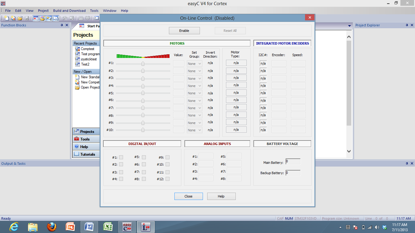
26 Opens IFI/Intelitek Loader window Screenshot of easyc V4 startup window


27 C Code Window Shows code in text format Function Block Window Drag and drop these into the programming window Block Programming Window Shows your code in a graphic block diagram format
 -127 = full cw (servo) or full speed forward (motor) 0 = null (servo) or off")
28 Mapping Your Robot This is the full range of speed control for both motors and servo s 127 = full ccw (servo) or full speed reverse (motor) -127 = full cw (servo) or full speed forward (motor) 0 = null (servo) or off (motor)
29
Servo Info and Centering
 Info and Centering A servo is a mechanical motorized device that can be instructed to move the output shaft attached to a servo wheel or arm to a specified position. Inside the servo box is a DC motor
Downloading a Sample Program over USB
 Downloading a Sample Program over USB This document is a guide for downloading and running programs on the VEX Cortex using the USB A-to-A cable. You will need: 1 VEX Cortex Microcontroller with one 7.2V
INTRODUCTION TO SERIAL ARM
 INTRODUCTION TO SERIAL ARM A robot manipulator consists of links connected by joints. The links of the manipulator can be considered to form a kinematic chain. The business end of the kinematic chain of
EasyC. Programming Tips
 EasyC Programming Tips PART 1: EASYC PROGRAMMING ENVIRONMENT The EasyC package is an integrated development environment for creating C Programs and loading them to run on the Vex Control System. Its Opening
Six-servo Robot Arm. DAGU Hi-Tech Electronic Co., LTD www.arexx.com.cn. Six-servo Robot Arm
 Six-servo Robot Arm 1 1, Introduction 1.1, Function Briefing Servo robot, as the name suggests, is the six servo motor-driven robot arm. Since the arm has a few joints, we can imagine, our human arm, in
Bluetooth + USB 16 Servo Controller [RKI-1005 & RKI-1205]
![Bluetooth + USB 16 Servo Controller [RKI-1005 & RKI-1205]](/thumbs/40/21161302.jpg "Bluetooth + USB 16 Servo Controller [RKI-1005 & RKI-1205]") Bluetooth + USB 16 Servo Controller [RKI-1005 & RKI-1205] Users Manual Robokits India info@robokits.co.in http://www.robokitsworld.com Page 1 Bluetooth + USB 16 Servo Controller is used to control up to
Bluetooth + USB 16 Servo Controller [RKI-1005 & RKI-1205] Users Manual Robokits India info@robokits.co.in http://www.robokitsworld.com Page 1 Bluetooth + USB 16 Servo Controller is used to control up to
ROBOTC Software Inspection Guide with Additional Help Documentation
 VEX ROBOTICS COMPETITION ROBOTC Software Inspection Guide with Additional Help Documentation VEX Cortex Software Inspection Steps: 1. Cortex Firmware Inspection using ROBOTC 2. Testing Cortex Robots using
Using the VEX Cortex with ROBOTC
 Using the VEX Cortex with ROBOTC This document is a guide for downloading and running programs on the VEX Cortex using ROBOTC for Cortex 2.3 BETA. It is broken into four sections: Prerequisites, Downloading
Testing Robots Using the VEXnet Upgrade
 Testing Robots Using the VEXnet Upgrade This document is an inspection guide for VEX v1.5 microcontroller-based robots. Use this document to test if a robot using the VEXnet Upgrade is competition ready.
Wireless Security Camera
 Wireless Security Camera Technical Manual 12/14/2001 Table of Contents Page 1.Overview 3 2. Camera Side 4 1.Camera 5 2. Motion Sensor 5 3. PIC 5 4. Transmitter 5 5. Power 6 3. Computer Side 7 1.Receiver
Radio Control System
 Radio Control System The Radio Control System consists of the control transmitter unit held by the operator and the receiver with its associated components in the robot. The Radio Control Transmitter converts
Programming the VEX Robot
 Preparing for Programming Setup Before we can begin programming, we have to set up the computer we are using and the robot/controller. We should already have: Windows (XP or later) system with easy-c installed
Radio Control System
 Radio Control System The Radio Control System consists of the control transmitter unit held by the operator and the receiver with its associated components in the robot. The Radio Control Transmitter converts
Eric Mitchell April 2, 2012 Application Note: Control of a 180 Servo Motor with Arduino UNO Development Board
 Eric Mitchell April 2, 2012 Application Note: Control of a 180 Servo Motor with Arduino UNO Development Board Abstract This application note is a tutorial of how to use an Arduino UNO microcontroller to
B0099 - Robo Claw 2 Channel 5A Motor Controller Data Sheet
 B0099 - Robo Claw 2 Channel 5A Motor Controller Feature Overview: 2 Channel at 5A, Peak 7A Hobby RC Radio Compatible Serial Mode TTL Input Analog Mode 2 Channel Quadrature Decoding Thermal Protection Lithium
Talon and Talon SR User Manual
 Talon and Talon SR User Manual Brushed DC motor controller Version 1.3 Cross the Road Electronics, LLC www.crosstheroadelectronics.com Cross The Road Electronics, LLC Page 1 4/2/2013 Device Overview Clear,
Selecting and Implementing H-Bridges in DC Motor Control. Daniel Phan A37005649
 Selecting and Implementing H-Bridges in DC Motor Control Daniel Phan A37005649 ECE 480 Design Team 3 Spring 2011 Abstract DC motors can be used in a number of applications that require automated movements.
VEHICLE SPEED CONTROL SYSTEM
 PL VEHICLE SPEED CONTROL SYSTEM 8H - 1 VEHICLE SPEED CONTROL SYSTEM TABLE OF CONTENTS page DESCRIPTION AND SPEED CONTROL SYSTEM...1 SPEED CONTROL SERVO-PCM OUTPUT....2 SPEED CONTROL SWITCHES PCM INPUT...2
Servo Motors (SensorDAQ only) Evaluation copy. Vernier Digital Control Unit (DCU) LabQuest or LabPro power supply
 Evaluation copy. Vernier Digital Control Unit (DCU) LabQuest or LabPro power supply") Servo Motors (SensorDAQ only) Project 7 Servos are small, relatively inexpensive motors known for their ability to provide a large torque or turning force. They draw current proportional to the mechanical
Servo Motors (SensorDAQ only) Project 7 Servos are small, relatively inexpensive motors known for their ability to provide a large torque or turning force. They draw current proportional to the mechanical
Hand Crank Generator (9 May 05) Converting a Portable Cordless Drill to a Hand Crank DC Generator
 Converting a Portable Cordless Drill to a Hand Crank DC Generator") Converting a Portable Cordless Drill to a Hand Crank DC Generator The unit is light weight (2.5 lb), portable, low cost ($10-$20) and can be used to recharge single cell batteries at from 1-3.5 amps. It
Converting a Portable Cordless Drill to a Hand Crank DC Generator The unit is light weight (2.5 lb), portable, low cost ($10-$20) and can be used to recharge single cell batteries at from 1-3.5 amps. It
UPS PIco. to be used with. Raspberry Pi B+, A+, B, and A. HAT Compliant. Raspberry Pi is a trademark of the Raspberry Pi Foundation
 UPS PIco Uninterruptible Power Supply with Peripherals and I 2 C control Interface to be used with Raspberry Pi B+, A+, B, and A HAT Compliant Raspberry Pi is a trademark of the Raspberry Pi Foundation
Using Arduino Microcontrollers to Sense DC Motor Speed and Position
 ECE480 Design Team 3 Using Arduino Microcontrollers to Sense DC Motor Speed and Position Tom Manner April 4, 2011 page 1 of 7 Table of Contents 1. Introduction ----------------------------------------------------------
User manual DinaSys DTC/DTS and DTC/DTZ
 PiCommIT has developed the DinaSys DTC/DTS and DinaSys DTC/DTZ turntable controller for the Fleischmann / Marklin Turntables in scale H0, H0m, TT, N and Z. One of the most important starting point was
Be careful when designing robots with multiple motors under simultaneous or heavy loading. There are three main points to consider:
 One of the most frustrating things that can happen to a team is losing control of their robot during a match. Please consider the following things that have been seen to cause problems at competition:
FLYPORT Wi-Fi 802.11G
 FLYPORT Wi-Fi 802.11G System on module 802.11g WIFI - Infrastructure mode - softap mode - Ad hoc mode Microchip PIC 24F 16 bit processor Microchip MRF24WG0MA/MB - Native WiFi 802.11g transceiver - PCB
Massachusetts Institute of Technology
 Objectives Massachusetts Institute of Technology Robotics: Science and Systems I Lab 1: System Overview and Introduction to the µorcboard Distributed: February 4, 2015, 3:30pm Checkoffs due: February 9,
TDAS G5-DB Hardware User s Manual
 TDAS G5-DB Hardware User s Manual July 2003 Rev. 1A Table of Contents DTS Support... 3 Introducing the TDAS G5-DB... 4 Summary of TDAS G5-DB Features... 4 Basic Care and Handling... 4 Shock Rating...5
Motion. Table of Contents: Introduction to the Motion Subsystem 3.2. Concepts to Understand 3.8. Subsystem Interactions 3.26. Motion.
 Motion Table of Contents: Introduction to the Motion Subsystem 3.2 Concepts to Understand 3.8 Subsystem Interactions 3.26 3 1 Introduction to the Motion Subsystem The Motion Subsystem comprises all the
UniPi technical documentation REV 1.1
 technical documentation REV 1.1 Contents Overview... 2 Description... 3 GPIO port map... 4 Power Requirements... 5 Connecting Raspberry Pi to UniPi... 5 Building blocks... 5 Relays... 5 Digital Inputs...
RCDC1 Radio Controlled Device Controller- 1 Channel
 RCDC1 Radio Controlled Device Controller- 1 Channel When the Mode Switch is in Position 1, Moving the joystick forward turns on the relay. When the joystick returns to center, the relay goes off (momentary
CONTENTS. What is ROBOTC? Section I: The Basics
 BEGINNERS CONTENTS What is ROBOTC? Section I: The Basics Getting started Configuring Motors Write Drive Code Download a Program to the Cortex Write an Autonomous Section II: Using Sensors Sensor Setup
Dr Robot C# Advance Sputnik Demo Program
 25 Valleywood Drive, Unit 20 Markham, Ontario, L3R 5L9, Canada Tel: (905) 943-9572 Fax: (905) 943-9197 Support@DrRobot.com Dr Robot C# Advance Sputnik Demo Program Version: 1.0.0 June 2008-1 - Copyright
Electric Landing Gear controllers and sequencer LGC12 / LGC 13C
 Electric Landing Gear controllers and sequencer LGC12 / LGC 13C Users Guide. Torrent d en Puig, 31. 08358, Arenys de Munt, Barcelona,Catalonia,Spain E-mail: info@xicoy.com. Fax: +34 933 969 743 web: www.xicoy.com
DIY QUAD. Build Manual V.A 2014
 DIY QUAD Build Manual V.A 2014 1 Contents Thanks for purchasing a DIY Quad! These instructions will show you how to assemble a Quad using the Pixhawk autopilot system and ArduCopter/APM:Copter firmware.
A 5 Degree Feedback Control Robotic Arm (Haptic Arm)
") A 5 Degree Feedback Control Robotic Arm (Haptic Arm) 1 Prof. Sheetal Nirve, 2 Mr.Abhilash Patil, 3 Mr.Shailesh Patil, 4 Mr.Vishal Raut Abstract: Haptics is the science of applying touch sensation and control
A 5 Degree Feedback Control Robotic Arm (Haptic Arm) 1 Prof. Sheetal Nirve, 2 Mr.Abhilash Patil, 3 Mr.Shailesh Patil, 4 Mr.Vishal Raut Abstract: Haptics is the science of applying touch sensation and control
DMX-K-DRV. Integrated Step Motor Driver + (Basic Controller) Manual
 Manual") DMX-K-DRV Integrated Step Motor Driver + (Basic Controller) Manual DMX-K-DRV Manual page 1 rev 1.33 COPYRIGHT 2007 ARCUS, ALL RIGHTS RESERVED First edition, June 2007 ARCUS TECHNOLOGY copyrights this document.
DMX-K-DRV Integrated Step Motor Driver + (Basic Controller) Manual DMX-K-DRV Manual page 1 rev 1.33 COPYRIGHT 2007 ARCUS, ALL RIGHTS RESERVED First edition, June 2007 ARCUS TECHNOLOGY copyrights this document.
UPiS - Uninterruptible Power intelligent Supply
 UPiS - Uninterruptible Power intelligent Supply www.pimodules.com Introduction The UPiS is an Advanced Powering add-on Module for the RaspberryPi that adds a wealth of additional features to the powering
Draper Low Voltage, Remote Control, Serial and Network Wiring Guide
 Draper Low Voltage, Remote Control, Serial and Network Wiring Guide Copyright 2007 Draper Inc. Form LV-RC-Serial-Network_Wiring07 Print ed in U.S.A. Draper Low Voltage, Remote Control, Serial and Network
Model: 616-146v2 Quick Setup Guide DC: 071015 Atomic Projection Alarm with Indoor and Outdoor Temperature
 Model: 616-146v2 Quick Setup Guide DC: 071015 Atomic Projection Alarm with Indoor and Outdoor Temperature Snooze/Backlight BUTTONS Time, Alarm with Snooze, & Calendar Projection Arm Rotates 180 Indoor/Outdoor
Technical Specifications: The specifications represent a particular hardware platform. Application-specific software is provided.
 Preliminary TECHNICAL DATASHEET #TDAX020700 HYDRAULIC VALVE CONTROLLER 24 I/O 5 Analog and 6 Digital Inputs 1 Temperature Sensor and 1 RPM Sensor Interface 2 PWM Inputs 6 Proportional and 4 ON/OFF Current
Renewable Energy Monitor User Manual And Software Reference Guide. sales@fuelcellstore.com (979) 703-1925
 703-1925") Renewable Energy Monitor User Manual And Software Reference Guide sales@fuelcellstore.com (979) 703-1925 1 Introducing the Horizon Renewable Energy Monitor The Renewable Energy Monitor is an educational
Renewable Energy Monitor User Manual And Software Reference Guide sales@fuelcellstore.com (979) 703-1925 1 Introducing the Horizon Renewable Energy Monitor The Renewable Energy Monitor is an educational
TOSR0X-D. USB/Wireless Timer Relay Module. User Manual. Tinysine Electronics @ 2013 Version 1.0
 TOSR0X-D USB/Wireless Timer Relay Module User Manual Tinysine Electronics @ 2013 Version 1.0 INTRODUCTION This USB/Wireless Timer Relay Module allows computer control switching of external devices by using
RC Camera Control. User Guide v1.2. 10/20/2012
 RC Camera Control User Guide v1.2 10/20/2012 kristaps_r@rcgroups INTRODUCTION RC Camera Control board (RCCC) is multifunctional control board designed to for aerial photography or First Person Video flying.
Using the Motor Controller
 The Motor Controller is designed to be a convenient tool for teachers and students who want to use math and science to make thing happen. Mathematical equations are the heart of math, science and technology,
Pulse Width Modulation Applications
 Pulse Width Modulation Applications Lecture 21 EE 383 Microcomputers Learning Objectives What is DTMF? How to use PWM to generate DTMF? How to use PWM to control a servo motor? How to use PWM to control
Hand Gestures Remote Controlled Robotic Arm
 Advance in Electronic and Electric Engineering. ISSN 2231-1297, Volume 3, Number 5 (2013), pp. 601-606 Research India Publications http://www.ripublication.com/aeee.htm Hand Gestures Remote Controlled
PolyBot Board. User's Guide V1.11 9/20/08
 PolyBot Board User's Guide V1.11 9/20/08 PolyBot Board v1.1 16 pin LCD connector 4-pin SPI port (can be used as digital I/O) 10 Analog inputs +5V GND GND JP_PWR 3-pin logic power jumper (short top 2 pins
USER MANUAL V5.0 ST100
 GPS Vehicle Tracker USER MANUAL V5.0 ST100 Updated on 15 September 2009-1 - Contents 1 Product Overview 3 2 For Your Safety 3 3 ST100 Parameters 3 4 Getting Started 4 4.1 Hardware and Accessories 4 4.2
PRODUCTIVITY THROUGH INNOVATION 600 CONTROL DIRECT DRIVE TECHNICAL/OPERATION MANUAL
 Rev. D PRODUCTIVITY THROUGH INNOVATION 600 CONTROL DIRECT DRIVE TECHNICAL/OPERATION MANUAL 10 BORIGHT AVENUE, KENILWORTH NEW JERSEY 07033 TELEPHONE: 800-524-0273 FAX: 908-686-9317 TABLE OF CONTENTS Page
Series 6000 Torque measured metal bellow coupling
 Properties Free of float metal bellow coupling with integrated torque measurement Non-contact measurement system, high robustness High torsional stiffness Limited torque of inertia Performance Measurement
MANUAL FOR RX700 LR and NR
 MANUAL FOR RX700 LR and NR 2013, November 11 Revision/ updates Date, updates, and person Revision 1.2 03-12-2013, By Patrick M Affected pages, ETC ALL Content Revision/ updates... 1 Preface... 2 Technical
INSTALLATION INSTRUCTIONS
 LIGHTING CONTROL PANELS 4 AND 8 RELAYS INSTALLATION INSTRUCTIONS INSTALLATION OVERVIEW The installation instructions contained in this document are provided as a guide for proper and reliable installation.
with Electronic Assistant
 TECHNICAL DATASHEET #TDAX100200 BLDC Motor Drive Drives a 12V, 24V or 48V BLDC motor Bidirectional, up to 25A Smooth speed control using Hall Sensors CAN (SAE J1939) with Electronic Assistant Features:
System theremino MasterDIL-V3
 System theremino MasterDIL-V3 System theremino - MasterDIL-V3 - Datasheet - March 8, 2013 - Page 1 The Master module The "Master" is the main module of the system Theremino. It puts in communication the
Best Robotics Sample Program Quick Start
 Best Robotics Sample Program Quick Start BEST Robotics Programming -- Sample Program Quick Start Page 1 Overview The documents describe the program "Best Competition Template.c" which contains the sample
=============================== WARNING
 =============================== WARNING EXPLANATION OF GRAPHICAL SYMBOLS This symbol is intended to alert the user to the presence of unprotected dangerous voltage" within the product's enclosure that
Model 2300DR Installation Guide
 Model 2300DR Installation Guide POWER ACCESS CORPORATION P.O. BOX 1050 170 MAIN STREET NEW HARTFORD, CT 06057 800-344-0088 WEBSITE: www.power-access.com EMAIL: salesinfo@power-access.com 1 STANDARD PARTS
Digi-Motor Installation Guide
 Digi-Motor Installation Guide Installation Video...located at marsdelivers.com Digi-Motor Installation Guide Digi-Motor For technical assistance with your Azure Digi-Motor, call the MARS technical support
ezsystem elab16m Project 1F: Alarm System (Full Project description)
") ezsystem elab16m Project 1F: Alarm System (Full Project description) ezsystem The aim of ezsystem is to enable Creativity and Innovation at an early age in a Problem Based Learning (PBL) approach. ezsystem
ezsystem elab16m Project 1F: Alarm System (Full Project description) ezsystem The aim of ezsystem is to enable Creativity and Innovation at an early age in a Problem Based Learning (PBL) approach. ezsystem
Flight Controller. Mini Fun Fly
 Flight Controller Mini Fun Fly Create by AbuseMarK 0 Mini FunFly Flight Controller Naze ( Introduction 6x6mm. 6 grams (no headers, 8 grams with). 000 degrees/second -axis MEMS gyro. auto-level capable
Transmitter Interface Program
 Transmitter Interface Program Operational Manual Version 3.0.4 1 Overview The transmitter interface software allows you to adjust configuration settings of your Max solid state transmitters. The following
TETRIX Getting Started Guide. Dispenser Building Guide. Step 1. Parts Needed. Tip. 1x Single-Servo Motor Bracket. 1x 96 mm Channel
 Step 1 1x 96 mm Channel 1x Single-Servo Motor Bracket 3x 1/2" SHCS 3x Kep Nut Tip Ensure that the teeth of the nut face the head of the screw. 173 Extensions Step 2 1x Servo Horn 1x Flat Bracket 3x 5/16"
Contactless Encoder RI360P0-QR24M0-INCRX2-H1181
 Compact, rugged housing Many mounting possibilities Status displayed via LED Immune to electromagnetic interference 1024 pulses per revolution (default) 360, 512, 1000, 1024, 2048, 2500, 3600, 4096, parametr.
HOBBY SERVO FUNDAMENTALS BY: DARREN SAWICZ
 HOBBY SERVO FUNDAMENTALS BY: DARREN SAWICZ I NTRODUCTION H obby servos are a popular and inexpensive method of motion control. They provide an off-the-shelf solution for most of the R/C and robotic hobbyist's
Microcontroller Programming Beginning with Arduino. Charlie Mooney
 Microcontroller Programming Beginning with Arduino Charlie Mooney Microcontrollers Tiny, self contained computers in an IC Often contain peripherals Different packages availible Vast array of size and
Modern Robotics, Inc Core Device Discovery Utility. Modern Robotics Inc, 2015
 Modern Robotics, Inc Core Device Discovery Utility Modern Robotics Inc, 2015 Version 1.0.1 October 27, 2015 Core Device Discovery Application Guide The Core Device Discovery utility allows you to retrieve
MidiStream. UHF Wireless MIDI System Operating Manual
 MidiStream UHF Wireless MIDI System Operating Manual Introduction Congratulations on your purchase of the MidiStream UHF wireless MIDI system. The MidiStream system is very easy to use, but please take
D.C. Motors. Products and specifications subject to change without notice.
 D.C. Motors Order/Technical Support - Tel: (8) 677-5 / FAX: (8) 677-865 / www.crouzet-usa.com / DC Motors Selection guide Gearbox Speed Torque max (Nm).5. Type of Gearbox 8 8 8. Power usable (w) Torque
AEO Head Movement Tracker X-GYRO 1000 USER MANUAL(V1.1bata 20091019)
") AEO Head Movement Tracker X-GYRO 1000 USER MANUAL(V1.1bata 20091019) Introduction: X-GYRO 1000 is a two axis head tracking system, based on G sensor technique, designed for tracking complicated three-dimensional
AEO Head Movement Tracker X-GYRO 1000 USER MANUAL(V1.1bata 20091019) Introduction: X-GYRO 1000 is a two axis head tracking system, based on G sensor technique, designed for tracking complicated three-dimensional
WIRELESS STATUS MONITOR
 INSTALLATION INSTRUCTIONS WIRELESS STATUS MONITOR (WSM or AUWSM) The most current version of this document is available for download at: http://www.ir-swa.com P/N: M053-032-D Schlage 245 W. Roosevelt Road,
ECE 495 Project 3: Shocker Actuator Subsystem and Website Design. Group 1: One Awesome Engineering
 ECE 495 Project 3: Shocker Actuator Subsystem and Website Design Group 1: One Awesome Engineering Luquita Edwards Evan Whetsell Sunny Verma Thomas Ryan Willis Long I. Executive Summary The main goal behind
TX GSM SMS Auto-dial Alarm System. Installation and User Manual
 TX GSM SMS Auto-dial Alarm System Installation and User Manual Product Features: 1. 16 wireless zones, 3 wired zones alarm system, suitable for small to medium size offices and homes. 2. The system uses
GSM Interfacing Board
 Campus Component Pvt. Ltd. DISCLAIMER Information furnished is believed to be accurate and reliable at the time of publication. However, Campus Component Pvt. Ltd. assumes no responsibility arising from
User Manual Wireless HD AV Transmitter & Receiver Kit
 Ma User Manual REV.1.0 Thank you for purchasing this. Please read the following instructions carefully for your safety and prevention of property damage. Do not use the product in the extreme hot, cold,
User s Manual of Board Microcontroller ET-MEGA2560-ADK ET-MEGA2560-ADK
 User s Manual of Board Microcontroller ET-MEGA2560-ADK ET-MEGA2560-ADK Because Arduino that is the development project on AVR MCU as Open Source has been published, it is popular and widespread shortly.
Data Sheet. Adaptive Design ltd. Arduino Dual L6470 Stepper Motor Shield V1.0. 20 th November 2012. L6470 Stepper Motor Shield
 Arduino Dual L6470 Stepper Motor Shield Data Sheet Adaptive Design ltd V1.0 20 th November 2012 Adaptive Design ltd. Page 1 General Description The Arduino stepper motor shield is based on L6470 microstepping
Quick Start Guide. MRB-KW01 Development Platform Radio Utility Application Demo MODULAR REFERENCE BOARD
 Quick Start Guide MRB-KW01 Development Platform Radio Utility Application Demo MODULAR REFERENCE BOARD Quick Start Guide Get to Know the MRB-KW01x Module UART Selector ANT 1 RFIO (TX/RX) USB 2.0 Serial
User and installation manual
 User and installation manual aquaero 5 The information contained in this manual is subject to change without prior notice. All rights reserved. Current as of April 2011 ENGLISH: PAGE 1 DEUTSCH: SEITE 13
Digital I/O: OUTPUT: Basic, Count, Count+, Smart+
 Digital I/O: OUTPUT: Basic, Count, Count+, Smart+ The digital I/O option port in the 4-Series provides us with 4 optically isolated inputs and 4 optically isolated outputs. All power is supplied externally.
Massachusetts Institute of Technology Department of Electrical Engineering and Computer Science 6.115 Microprocessor Project Laboratory
 Massachusetts Institute of Technology Department of Electrical Engineering and Computer Science 6.115 Microprocessor Project Laboratory Connecting your PSoC Evaluation Board It is easy and fun to avoid
TECHNICAL DATASHEET #TD1404AX PWM CONTROLLED SOLENOID DRIVER
 TECHNICAL DATASHEET #TD1404AX PWM CONTROLLED SOLENOID DRIVER (PWM Input, 1.2A or 2A Output, Metal Box or PCB) PCB Board - P/N: PWMC-PCB-2A, PWMC-PCB-1.2A Packaged Driver (metal box with 1.5 m (5 ft.) cable)
EZmoto V2. Product description Rev. 6 10/01/2014. EZmoto V2 Product description Rev.6 10/01/2014
 EZmoto V2 Product description Rev. 6 10/01/2014 1 Contents 1. Overview... 3 2. Hardware Interface Description... 3 2.1 Main features of the EZmoto... 3 2.2 Hardware block diagram... 4 2.3 Internal Hardware
The self-starting solar-powered Stirling engine
 The self-starting solar-powered Stirling engine This project began at the request of an artist who had proposed a Stirling-engine-powered sculpture to a client. The engine only had to run, not really produce
Introduction. Drenth Motorsport Gearboxes Fleuweweg 10 7468 AG Enter The Netherlands Phone: +31 (0)547 38 26 96 Fax: +31 (0)547 38 20 65
547 38 26 96 Fax: +31 (0)547 38 20 65") 25.03.0023 Introduction The display comes with a software application. With the software application information shown on the display can be adjusted. There are different modes to adjust: the shape of
25.03.0023 Introduction The display comes with a software application. With the software application information shown on the display can be adjusted. There are different modes to adjust: the shape of
Application Information Fully Integrated Hall Effect Motor Driver for Brushless DC Vibration Motor Applications
 Application Information Fully Integrated Hall Effect Motor Driver for Brushless DC Vibration Motor Applications By Shaun Milano Vibration motors are used in a variety of applications including mobile phone
IPX AUTOMATIC IP NETWORK LOSS BACKUP A/B SWITCH INSTRUCTION BOOK IB6444-02
 IPX AUTOMATIC IP NETWORK LOSS BACKUP A/B SWITCH INSTRUCTION BOOK IB6444-02 TABLE OF CONTENTS DESCRIPTION 2 MOUNTING INSTRUCTIONS 2 HOW TO CABLE THE IPX 2/3 POWER SUPPLY INSTALLATION 3 OPERATION 3 CARE
Electronic Power Control
 Service. Self-Study Programme 210 Electronic Power Control Design and Function With the Electronic Power Control system, the throttle valve is actuated only by an electric motor. This eliminates the need
Introduction. New manuals are written like a slide show This approach is to have more diagrams and images to improve learning.
 Introduction New manuals are written like a slide show This approach is to have more diagrams and images to improve learning. We can adapt each slide to keep updated the document. It is very easy and fast.
Industrial Automation Training Academy. PLC, HMI & Drives Training Programs Duration: 6 Months (180 ~ 240 Hours)
") nfi Industrial Automation Training Academy Presents PLC, HMI & Drives Training Programs Duration: 6 Months (180 ~ 240 Hours) For: Electronics & Communication Engineering Electrical Engineering Instrumentation
nfi Industrial Automation Training Academy Presents PLC, HMI & Drives Training Programs Duration: 6 Months (180 ~ 240 Hours) For: Electronics & Communication Engineering Electrical Engineering Instrumentation
RPLIDAR. Low Cost 360 degree 2D Laser Scanner (LIDAR) System Development Kit User Manual. 2014-2 Rev.1
 System Development Kit User Manual. 2014-2 Rev.1") RPLIDAR Low Cost 360 degree 2D Laser Scanner (LIDAR) Development Kit User Manual 2014-2 Rev.1 Team Contents: 1. OVERVIEW... 2 ITEMS IN DEVELOPMENT KIT... 2 RPLIDAR... 2 USB ADAPTER... 3 2. CONNECTION AND
RPLIDAR Low Cost 360 degree 2D Laser Scanner (LIDAR) Development Kit User Manual 2014-2 Rev.1 Team Contents: 1. OVERVIEW... 2 ITEMS IN DEVELOPMENT KIT... 2 RPLIDAR... 2 USB ADAPTER... 3 2. CONNECTION AND
Wireless Home Security Alarm System AM 500
 Wireless Home Security Alarm System AM 500 12 MONTH GUARANTEE Installation & Operating Instructions INTRODUCTION The AM500 is a simple self-contained alarm system. It protects the home by sounding a siren
Wireless Home Security System
 Wireless Home Security System Group: D14 Members: Vaibhav Singh (05D07026) Abhishek Tiwari (05D07028) Sauvik Chowdhury (05D07029) 1. Abstract The project is aimed at designing a low cost and reliable wireless
PROJECT PRESENTATION ON CELLPHONE OPERATED ROBOTIC ASSISTANT
 PROJECT PRESENTATION ON CELLPHONE OPERATED ROBOTIC ASSISTANT ELECTRONICS ENGINEERING DEPARTMENT SVNIT, SURAT-395007, INDIA Prepared by: Anurag Gupta (U05EC401) Dhrumeel Bakshi (U05EC326) Dileep Dhakal
Overview. 1. GPS data tracking via GSM SMS / GPRS. 2. GPS data logging in internal memory. 3. Alarm alert via GSM SMS / Dialing / GPRS
 Vehicle or Personal Position Tracking Vehicle Status and Speed Tracking Auto Accident Report Global Position System (GPS) Navigation System Anti theft Alarm System Overview 1. GPS data tracking via GSM
INSTRUCTION MANUAL. Specification: collective pitch 3D quadcopter. TYPE: Collective Pitch Electric 3D Quadcopter. Rotor Diameter: 118MM.
 collective pitch 3D quadcopter INSTRUCTION MANUAL Specification: TYPE: Collective Pitch Electric 3D Quadcopter Rotor Diameter: 118MM Length:635 MM Width: 365 MM Weight: 986g w/out battery Flying weight
SYSTEM 45. C R H Electronics Design
 SYSTEM 45 C R H Electronics Design SYSTEM 45 All in one modular 4 axis CNC drive board By C R Harding Specifications Main PCB & Input PCB Available with up to 4 Axis X, Y, Z, & A outputs. Independent 25
EVAL-UFDC-1/UFDC-1M-16
 Evaluation Board for Universal Frequency-to- Digital Converters UFDC-1 and UFDC-1M-16 EVAL-UFDC-1/UFDC-1M-16 FEATURES Full-Featured Evaluation Board for the Universal Frequency-to-Digital Converters UFDC-1
A-307. Mobile Data Terminal. Android OS Platform Datasheet
 A-307 Mobile Data Terminal Android OS Platform Datasheet Revision 1.1 July, 2013 Introduction A-307 Platform Overview Introduction A-307 Platform Overview The A-307 provides Original Equipment Manufacturers
Electric Motors and Drives
 EML 2322L MAE Design and Manufacturing Laboratory Electric Motors and Drives To calculate the peak power and torque produced by an electric motor, you will need to know the following: Motor supply voltage,
Specifying a Variable Frequency Drive s
 Specifying a Variable Frequency Drive s Put on by Bruce Reeves and Jeremy Gonzales Dykman Electrical Covering the Western US For all of your VFD and Soft Start and Motor Needs How To Specify a Variable