VORTEX 360 DUAL ROTATOR
|
|
|
- Helen Tyler
- 8 years ago
- Views:
Transcription
1 VORTEX 360 DUAL ROTATOR With Variable Speed Control Manual Ver. 4

2 AN INTRODUCTION TO YOUR VORTEX Thank you for your purchase of the Vortex 360. This product has been designed to provide you with reliable dual rotating gobo effects in your ETC Source 4 and Altman Shakespeare. It can accommodate both glass and metal size B gobos (86mm). Adjusting the speed and direction of the rotation is as simple as sliding a switch on the modular power adapter. Parts and Functions Below is a picture of the Vortex 360 and its power adapter with various components labeled. Motor Cover Transformer Assy. Motor Gobo Retaining Spring Gobo Stepper Ring (used only with steel gobos) Motor Pad Gobo Gear 8-32 x 3/8 Type F Vortex 360 rotator with power adapter (parts labeled) 2

3 INSTALLING GOBOS Metal Gobos 1) Remove gobo retaining spring from gobo gear. 2) Remove steel gobo stepper ring from gobo gear. 3) Place metal gobo into gobo gear. 4) Replace steel gobo stepper ring in gobo gear. 5) Replace gobo retaining spring in gobo gear. Metal gobo placed in Vortex 360. Note: Avoid using bent or damaged metal gobos as they may result in jamming of the mechanism, which can lead to damage of the motor. Glass Gobos 1) Remove gobo retaining spring from gobo gear. 2) Remove steel gobo stepper ring from gobo gear and put aside. It is not used with glass gobos. 3) Place glass gobo into gobo gear. 4) Replace gobo retaining plate in gobo gear. 3
 Remove gobo retaining spring from gobo gear. 2) Remove steel gobo stepper ring from gobo gear and put aside. It is not used with glass gobos.")
4 Glass gobo placed into Vortex 360. I N S TALLING THE VORTEX 360 IN THE FIXTURE 1) Open accessory slot (Iris Slot) on fixture. 2 ) Slide Vo rt ex 360 into fixture s accessory slot with m o t o r covering facing toward the front of the fixture. (This is i m p o rtant to avoid overheating the motor and to keep the shutters readily accessible.) 3) Use safety cable through handle of Vortex 360 to attach to fixed safety point. 4) Make sure power adapter cable is not touching any part of the fixture. Vortex 360 being installed in a fixture (re q u i red safety cable not shown). 4
 3) Use safety cable through handle of Vortex 360 to attach to fixed safety point.")
5 OPERATION The speed and rotation can be set by turning the potentiometer (on top of the unit) clickwise for faster and counter clockwise for slower. The direction of the rotation can be set by changing the position of the toggle switch. There is also an off feature (center position on the toggle switch) for changing gobos without having to unplug the unit or dial down the speed to 0. Note: The rotational speed of the Vortex 360 can be remotely c o n t ro l l e d by plugging the power adapter into an electronic dimmer output (set the power adapter to 12V for best results). However, the dimmer output must be compatible for use with transformers. Please check with the dimmer manufacturer before using the Vortex 360 in this fashion. Failure to use a compatible dimmer can result in overheating and/or damage to both the Vortex 360 and the dimmer. PRECAUTIONS Make sure gobos can rotate freely while in use. Jamming of a gobo wheel can cause the motor to burn out. Make sure motor cover is facing the front of the fixture. Failure to do so can result in motor overheating. Do not let Vortex 360 hang by power adapter cord. Always use a safety cable with the Vortex 360. After use, case may become very hot. If unit must be handled, use h a ndle as it is a thermoplastic and will remain cool to the touch. Do not use the Vo rtex 360 with a dimmer if the dimmer is not rated for power adapters. Do not rapidly heat and cool glass gobos as this will l i k ely cause them to bre a k. Ensure that you are using the flattest field p o s s i ble will also reduce change of breakage. Make sure power adapter cable is not touching any p a rt of the f i xture. 5
.")
6 TROUBLESHOOTING AND REPAIRS Gobos Not Rotating and Vortex 360 Motor Not Running Possibility #1 Gears are jammed Make sure nothing is preventing gears from rotating properly. If they will not rotate freely, don t try to force them. If they are jammed, remove the obstruction and test. Note that jammed gears may lead to a dead power adapter and/or motor. Possibility #2 Toggle switch is set to off (center position) Change the position of the toggle switch. Possibility #3 Power adapter is dead Meter pins 1 and 3 from the power adapter. The voltage read should match the rating on the power adapter itself. Po l a rity is not important.if output voltage is not within 15%, the tra n s fo rmer is not wo rking properly. Possibility #4 Wires to motor have come off Open cover and ve rify that wires have not become disconn e c t e d from motor. If this has occurred, simply solder back in place. Possibility #5 Motor is dead If possibl e, attach a different power adapter to the unit to ve rify that it is not the power adapter. If eve rything else has been c h e cked, then the motor should be replaced (see instru c t i o n s later). 6

7 Disconnect power immediately! Further operation could damage motor and/or power adapter. Gobos Not Rotating and Vortex Making Noise Possibility #1 Gears are jammed M a ke sure nothing is preventing gears from rotating properl y. If they will not rotate freely, don t try to force them. If they a r e j a m m e d,r e m ove the obstruction and test. Note that jammed gears m ay lead to a dead power adapter and/or motor. Possibility #2 Drive gear is loose If it sounds like the motor is spinning, but no gears are turning, the dri ve gear on the motor shaft may be loose. This wo u l d also allow the rest of the gears to rotate freely. It can be fixed by tightening the set screw on the dri ve gear with a 5/64" A l l e n key. Possibility #3 Motor is dead If possibl e, attach a different power adapter to the unit to ve rify that it is not the power adapter. If eve rything else has been c h e cked, then the motor should be replaced. CANNOT FOCUS IMAGE Possibility #1 Gobo is bent or broken Remove Vortex 360 from fixture and check both gobos. Possibility #2 Problem with fixture I n s e rt new gobo in pattern holder and place in fixture. Make sure that image can focus properly. Consult fixture manufacturer if this is the problem. 7

8 REPLACING THE MOTOR The Vortex 360 motor can be replaced fairly easily. You will need a 5/64" Allen key, needlenose pliers, small Phillips screw d ri ve r, a s o l d e ring iron, and solder. 1) Open front cover of Vortex ) Use the soldering iron to disconnect the wires fo rm the motor. 3 ) Use the 5/64" Allen key to loosen the set screw on the dri ve g e a r attached to the motor. If you cannot see the hole fo r the set screw in the side of the gear, you may need to use the screwdriver to rotate the gear. 4) Use the needle-nose pliers to loosen the motor attachment standoffs (2x, one on each side of the motor with a hex head at the top). Remove the standoffs, washer and O ring. 5 ) Lift the motor out and make sure not to lose the dri ve gear or motor pad. 6) Place the new motor into the Vortex 360 in place of the o l d o n e. M a ke sure that the motor pad is between the motor and the metal. You will need to put the shaft of the new motor through the drive gear as you do this. 7 ) Replace the motor attachment standoffs, O rings and washers and tighten with the needle-nose pliers (do not over-tighten). 8) Solder the motor wires onto the new motor. 9 ) Attach the power adapter and make sure the motor rotates properly (the shaft can be seen through the rear plate). The gears will p r o ba bly not rotate. Stop the motor when the flat side of the shaft is fa cing the side of the unit. 1 0 ) Rotate the dri ve gear until the set scew is aligned with the flat side of the motor shaft. Tighten down the set s c r ew. D ri ve gear should no longer spin freely. 1 1 ) Test Vo rt ex 360 out of the fixture to make sure it is all wo rking properl y. 8
 Use the needle-nose pliers to loosen the motor attachment standoffs (2x, one on each side of the motor with a hex head at the top). Remove the standoffs, washer and O ring.")
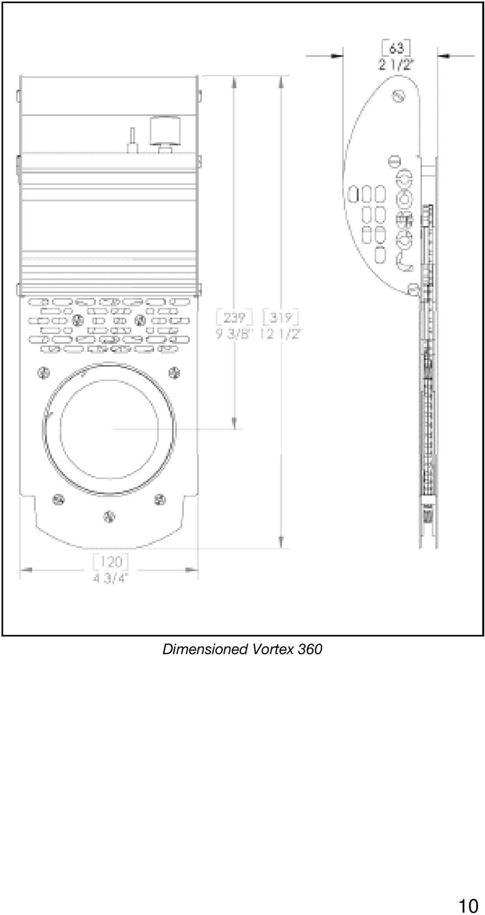
9 VORTEX 360 SPECIFICATIONS S i z e HxWxD x 4.75 x 2.5 (319mm x 120mm x 64mm) Unit - 2lb. 12oz lbs. (1.25 kg) Power adapter lbs. (.28 kg) Supported ETC Source 4 Fixtures Altman 1KL Supported Gobo Size Power Supply Standard B Size (64.5mm) image size Maximum (86mm) outer diameter. Plug-In transformer with NEMA 1-15 Plug 120 and 240 volt versions, 50/60Hz, 6W MAX, 100/.06amps, 120/.05, 200/.03, 240/.025 Output -12VDC, 6W Maximum Switchable Polarity Cord Length - 52 (1320mm) Connector - 3-pin Male DIN 9

10 Dimensioned Vortex
11 3-Pin DIN Receptacle #83001 Handle #83005 Motor Pad #23003 Speed Control Assembly # DC Motor #83004 Gobo Spring Clip #3006 Retaining Ring #83007 Replacement Parts Replacement power adapter; # Repairs, Warranty Issues and Parts For all repairs, wa r ranty issues and parts needs, please contact our service center. Rotad 1675 Brandywine Ave, Suite B Chua Vista, CA ext. 11 You can also call your local Rosco dealer for parts and information. 11

12 Rosco Laboratories, Inc. 52 Harbor View Ave., Stamford, CT (203) (800) ROSCO NY FAX (203) Los Angeles St., Glendale, CA (818) (800) ROSCO LA FAX: (818) Rosco Laboratories, Ltd Denison St. #44, Markham, Ontario, Canada L3R 4B4 (905) (888) ROSCO TO FAX: (905) Roscolab, Ltd. Blanchard Works, Kangley Bridge Rd., Sydenham, London SE26 5AQ England (20) FAX: (20) Rosco Iberica, S.A. Rosco Iberica, S.A. C/ Perfumeria, 21. Nave 8. Pol. Ind. La Mina, Colmenar Viejo, Madrid, Spain (34) Fax: (34) Rosco do Brasil Ltda. Rua Antonio De Barros, 827, São Paulo SP Brasil CEP (11) FAX: (11) Rosco Australia Pty Ltd. 42 Sawyer Lane, Artarmon 2064, New South Wales, Australia (02) FAX: (02)
 8659-2300 FAX: (20) 8659-3153 Rosco Iberica, S.A. Rosco Iberica, S.A. C/ Perfumeria, 21. Nave 8. Pol. Ind.")
I-CUE INTELLIGENT MIRROR. Operations Manual
 I-CUE INTELLIGENT MIRROR Operations Manual Table of Contents Product Overview pg 1 Product Description pg 2 Operation pg 2 Unpacking the unit pg 3 Control and power cables pg 3 Connections pg 4 Mounting
Other products available from Apollo
 Other products available from Apollo Smart Color Scrollers Smart Power PSU s Stainless Steel Gobos Glass Gobos Gel Filters Gel Miser Tape Dichroics Pattern Holders Donuts And Much More! Apollo Design Technology
OEM Manual MODEL 2350 ELECTRONIC DUAL CYLINDER SCALE
 OEM Manual MODEL 2350 ELECTRONIC DUAL CYLINDER SCALE Scaletron Industries, Ltd. Bedminster Industrial Park 53 Apple Tree Lane P.O. Box 365 Plumsteadville, PA 18949 USA Toll Free: 1-800-257-5911 (USA &
ELECTRIC KNIFE SHARPENER
 PRODUCT MANUAL- M109 MODEL 401 ELECTRIC KNIFE SHARPENER Please read thoroughly before operation and keep for future reference Model 401 Knife Sharpener Specifications Model No. #401 Power Requirements
Trillium 40 Axis Spring Tensioner Wire Replacement Instructions
 Trillium 40 Axis Spring Tensioner Wire Replacement Instructions 1 Overview The objective is to replace the broken axis spring tensioner wire. This requires the following tasks: 1. Remove the seismometer
SMART MOVE. Gobo Rotators. Smart Move Smart Move DMX Smart Move Jr. Smart Move Jr. DMX Simple Single
 SMART MOVE Gobo Rotators Smart Move Smart Move DMX Smart Move Jr. Smart Move Jr. DMX Simple Single Table 0f Contents Introduction 2 Product Description 2 Safety Information 3 Gobo Installation 4 Operating
Economy Combo Heat Press Manual Model No.: ECH-800
 Economy Combo Heat Press Manual Model No.: ECH-800 CONTENTS I. Assembly Drawing -----------------------------------------------------------------------------------2 II. Technical Parameters ------------------------------------------------------------------------------2
Heat Surge Model X5C Fire Place Insert Service Manual Applies to all units w/30000208 circuit board
 Heat Surge Model X5C Fire Place Insert Service Manual Applies to all units w/30000208 circuit board 2012 HS M4417A BR16597R-1 HEAT SURGE 8000 FREEDOM AVE, N. CANTON, OH 44720 330-244-8161 WWW.HEATSURGE.COM
Connecting the Channel A
 20 Edge Lighting. All Rights Reserved. Installation Instructions for Cirrus Channel Suspension T, Tubular Lens w/2sq or 2RD Canopy IMPORTANT INFORMATION - This product is suitable for indoor locations.
MCR1900 Media Converter 19-Slot Chassis
 MCR1900 Media Converter 19-Slot Chassis Installation Guide Part #5500304-11 Copyright Statement This document must not be reproduced in any way whatsoever, either printed or electronically, without the
SMD Rework Station TABLE OF CONTENTS
 SMD Rework Station Thank you for purchasing the Hakko 50B SMD Rework Station. The Hakko 50B is designed to solder and desolder surface mounted devices with hot air. Please read this manual before operating
Elecraft K3 KPA3 Power Connector Replacement Revision A Review, April 16, 2012 Copyright 2012, Elecraft, Inc. All Rights Reserved
 Introduction Elecraft K3 KPA3 Power Connector Replacement Revision A Review, April 16, 2012 Copyright 2012, Elecraft, Inc. All Rights Reserved The connectors furnishing high current to the KPA3 module
Fleck 4650. Service Manual INSTALLATION AND START-UP PROCEDURE TABLE OF CONTENTS JOB SPECIFICATION SHEET
 Fleck 4650 Service Manual TABLE OF CONTENTS JOB SPECIFICATION SHEET...1 INSTALLATION AND START-UP PROCEDURE...1 CONTROL VALVE DRIVE ASSEMBLY...2 CONTROL DRIVE ASSEMBLY FOR CLOCK...3 BYPASS VALVE ASSEMBLY...4
Triac Printed Circuit Board Replacement
 Technical Service Bulletin: Triac Printed Circuit Board Replacement TRONIC 5000C Pro Models: WH17, WH27, WH36 Introduction Fig. 1 ELECTRICITY IS EXTREMELY DANGEROUS. TAKE EXTRA PRECAUTIONS AND ENSURE ALL
16/32 Channel 1U Rack Mount CCTV Power Supply
 16/32 Channel 1U Rack Mount CCTV Power Supply Manual PH-A3224-GUQ Shown 16-Channel 32-Channel PTC PH-A1612-PUQ PH-A3224-PUQ Glass Fuse PH-A1612-GUQ PH-A3224-GUQ Industrial design 12 Amp 3 Amps per channel
Oceanscience Cable Chimp II Cableway ROV System User Guide and Warranty
 Oceanscience Cable Chimp II Cableway ROV System User Guide and Warranty Page 1 Table of Contents Introduction Page 3 Overview Page 3 Setup and Operation Page 5 Remote Control Page 6 Power Management Page
INSTALLATION AND OPERATING INSTRUCTIONS For Model GL1 Gate Locks
 Securitron Magnalock Corp. www.securitron.com ASSA ABLOY, the global leader Tel 800.624.5625 techsupport@securitron.com in door opening solutions INSTALLATION AND OPERATING INSTRUCTIONS For Model GL1 Gate
SERVICE PARTS LIST PAGE 1 OF 6 BASE ASSEMBLY SPECIFY CATALOG NO. AND SERIAL NO. WHEN ORDERING PARTS 12" DUAL BEVEL COMPOUND MITER SAW B27A
 PAGE 1 OF 6 BASE ASSEMBLY 00 0 EXAMPLE: Component Parts (Small #) Are Included When Ordering The Assembly (Large #). SPECIFY CATALOG NO. AND NO. WHEN ORDERING PARTS 1 02-80-0050 Thrust Bearing (1) 2 05-80-0510
Owners & Installation Manual for the Sheridan, Mountainair, Pine Valley and Old Forge Ceiling Fan Family
 Owners & Installation Manual for the Sheridan, Mountainair, Pine Valley and Old Forge Ceiling Fan Family Part of the Kiva Lighting Family Custom Lighting and Fans Since 1992 1312 12th St NW Albuquerque,
Express5800/120Ed. Rack Mount Kit Installation Procedures PN: 455-01607-001
 Express5800/120Ed Rack Mount Kit Installation Procedures PN: 455-01607-001 Proprietary Notice and Liability Disclaimer The information disclosed in this document, including all designs and related materials,
42U/45U 28" Wide Rack Installation & Service Guide
 42U/45U 28" Wide Rack Installation & Service Guide 96-00171-005 Rev B Important Information Information in this document is subject to change without notice and does not represent a commitment on the part
PRODUCT MANUAL - M090
 PRODUCT MANUAL - M090 MODEL 203/266 ELECTRIC CAN OPENER 1 SAFETY CAUTION: SEVERED CAN LIDS HAVE CUTTING EDGES. USE OF A PROTECTIVE GLOVE OR TONGS IS ADVISED WHEN HANDLING LIDS. WARNING To avoid risk of
TS93 EMR T/PT/TDE. Surface applied door closer
 TS EMR T/PT/TDE Surface applied door closer Installation instructions: Pull side track mount door closer with smoke detector (EMR T) Push side track mount door closer with smoke detector (EMR PT) Double
DANGER DANGER. General Information. Safety Is Your Responsibility. Ordering Parts. Contact Information
 Safety Safety Is Your Responsibility DANGER To avoid personal injury or death, carefully read and understand all instructions pertaining to the Anthony Liftgates product. Do not attempt to install, operate,
DP-DMX20L 4 CHANNEL DMX DIMMER PACK MODE MENU DISPLAY. OUTPUT: 10A/CH, TOTAL 20A Max. DMX CHANNEL RECEIVE TOTAL DMX CHANNEL DIMMER / SWITCH
 DP-DMX0L OUTPUT: 0A/CH, TOTAL 0A Max. CHANNEL DMX DIMMER PACK DISPLAY RECEIVE DMX CHANNEL TOTAL DMX CHANNEL DIMMER / SWITCH 8888 CHASE PROGRAM CHASE CHASE SPEED CHASE DIMMER MODE MENU Elation Professional
Introduction... 2. Using the PSU... 2. Mounting and Installation... 5. Compatibility List... 6. Mechanical Specifications... 6
 Introduction...................... 2 Using the PSU.................... 2 Mounting and Installation............ 5 Compatibility List.................. 6 Mechanical Specifications............ 6 Electrical
Congratulations on your purchase of the Great Planes SLOT MACHINE, the first truly easy way to cut hinge slots in your model airplanes.
 INSTRUCTION MANUAL Congratulations on your purchase of the Great Planes SLOT MACHINE, the first truly easy way to cut hinge slots in your model airplanes. The Slot Machine you have purchased is equipped
TERMINATION EQUIPMENT INSTRUCTION MANUAL TELE-PIERCE P/N 356-246
 TERMINATION EQUIPMENT INSTRUCTION MANUAL TELE-PIERCE P/N 356-246 OPERATION AND SERVICE INSTRUCTIONS AMPHENOL 157 SERIES TELE-PIERCE MULTI-WIRE TERMINATION TOOL 356-246 AMPHENOL TERMINATION SYSTEMS 1830
Operating Instructions Bedienungsanleitung Mode d emploi
 Operating Instructions Bedienungsanleitung Mode d emploi DW 400 www.bron-kobold.com Operating instructions DW 400 Before use Please read all the information contained in these operating instructions carefully.
Companion Service Guide
 Companion Service Guide This Service Guide contains: Troubleshooting Replacement Instructions Contact Information Golden Technologies 401 Bridge Street Old Forge, PA 18518 Toll-free: 800-624-6374 Fax:
Operator Manual 100 Series Coffee Grinders
 Operator Manual 100 Series Coffee Grinders Models 100 and 190SS Model 100 Model 190SS Specifications...2 Safety Information...2 Installation...3 Operation...3 Table of Contents Cleaning & Maintenance...6
Remote Head REMO ONE. Code 5750. Manual
 Remote Head REMO ONE Code 5750 Manual by sachtler. All rights reserved Version: 1.2/09/05 Issue date: September 2005 Order no.: srh20t010a We want you to receive Sachtler products that are always state
WE-350 Series ¼ Turn Electric Actuator
 WE-350 Series ¼ Turn Electric Actuator Operation and Installation Manual Pg 1 (Rev. 020113) Table of Contents 1.0 General 1.1 Pre-Installation Inspection 1.2 Storage 1.3 Features & General Information
Solstice/Sky Water Pump Replacement
 Solstice/Sky Water Pump Replacement The water pump on the Solstice/Sky is starting to need replacement on some vehicles. This guide will help in replacing the water pump while the engine is still in the
PRODUCT: WASHER / WASHER-DRYER COMBO MODEL: AW 120 / AW 122 / AW 125 AWD 120 / AWD 121 / AWD 129
 PRODUCT: WASHER / WASHER-DRYER COMBO MODEL: The information included in this Splendide Repair Manual may change without notice. Please see our web site www.splendide.com/service/docs.html for updates,
Standard Sleep Pod Side Entry Assembly Instructions
 Standard Sleep Pod Side Entry Assembly Instructions www.podtime.co.uk enquiries@podtime.co.uk Working House Ltd How to assemble your pod Pod assembly onsite is a relatively simple exercise for two people
AerAtron. Ceiling fans
 AerAtron Ceiling fans User Manual & Technical Specifications Models: e502 & e503 Australian edition 2011 Instructions...3 General precautions...3 Location and installation requirements for your fan...3
Networkfleet 3500 Product Line Installation Guide
 Networkfleet 3500 Product Line Installation Guide Light/Medium Duty (L3500) Heavy Duty (H3500) Universal (U3500) www.networkcar.com/fleet Customer Care: (866) 227-7323 customercare@networkcar.com Table
Pet hair clipper. Model 96822. Diagrams within this manual may not be drawn proportionally.
 Pet hair clipper Model 96822 Cleaning And Operation Instructions Diagrams within this manual may not be drawn proportionally. Due to continuing improvements, actual product may differ slightly from the
Installation and instruction manual for Laing DDC pumps
 Installation and instruction manual for Laing DDC pumps Application The Laing DDC series pumps are primarily used for the circulation of cooling liquid in liquid cooled computers. Construction - The Laing
Quickie Rhapsody Service Manual
 Quickie Rhapsody Service Manual 2006 Sunrise Medical Inc. 101976 Rev A Quickie Rhapsody Service Manual Contents Introduction... 0.1 VR2 Controller... 0.2 Plugs/Connectors... 0.3 Basic Tool List & Main
AerAtron. Ceiling fans
 AerAtron Ceiling fans User Manual & Technical Specifications Models: e502 & e503 Electricians PLEASE FOLLOW THESES INSTRUCTIONS CAREFULLY & PAY SPECIAL ATTENTION TO THE NOTES NOTES WILL ASSIST WITH AN
CONNECTOR AMPLIFIER FOR PROPORTIONAL VALVES (4-20 ma Input Version)
") TECHNICAL DATASHEET #TD1102AX CONNECTOR AMPLIFIER FOR PROPORTIONAL VALVES (4-20 ma Input Version) Part Number: Connector Amplifier CAPV-H-4-20MA-x complete with cable CAPV-4C-yM Where: x = current output
TECHNICAL DATASHEET #TD1102AX CONNECTOR AMPLIFIER FOR PROPORTIONAL VALVES (4-20 ma Input Version) Part Number: Connector Amplifier CAPV-H-4-20MA-x complete with cable CAPV-4C-yM Where: x = current output
Wall-Mounting your HP computer. User Guide
 Wall-Mounting your HP computer User Guide The only warranties for Hewlett-Packard products and services are set forth in the express statements accompanying such products and services. Nothing herein should
Model 5600 & 5600 Econominder
 Service Manual IMPORTANT: Fill in pertinent information on page 3 for future reference. Table of Contents Job Specification Sheet...................................................................................
OPL BASIC. Dosing System for Professional Laundry machines. Contents
 OPL BASIC Dosing System for Professional Laundry machines Contents 1 Getting Started. Page 2 2 Installation. Page 4 3 Set Up & Operation. Page 8 4 Maintenance & Accessories. Page 10 5 Troubleshooting Page
Front brakes (FN- 3), servicing
, servicing") j a t Front brakes (FN- 3), servicing 46-1 Front brakes, servicing Note: Install complete repair kit. After replacing brake pads and before moving vehicle, depress brake pedal several times firmly to properly
j a t Front brakes (FN- 3), servicing 46-1 Front brakes, servicing Note: Install complete repair kit. After replacing brake pads and before moving vehicle, depress brake pedal several times firmly to properly
2100, 2200, 2300, 4100, 6200, MPB Series Side Mount Drive Package for Standard Load 90 Industrial Gearmotors
 00, 00, 300, 400, 600, MPB Series Side Mount Drive Package for Standard Load 90 Industrial Gearmotors Installation, Maintenance & Parts Manual Featuring: Technology DORNER MFG. CORP. INSIDE THE USA OUTSIDE
Table of Contents. Overview 1. Pump Disassembly 2. Control Disassembly / Reassembly 7. Pump Reassembly 13. Adjustment Procedures DR Control 19
 Table of Contents Overview 1 Pump Disassembly 2 Control Disassembly / Reassembly 7 Pump Reassembly 13 Adjustment Procedures DR Control 19 Adjustment Procedures DRG Control 20 Adjustment Procedures DFR
HP Laser Jet 4200/4240/4250/4300/4350 Swing Plate
 HP Laser Jet 4200/4240/4250/4300/4350 Swing Plate 1 Swing Plate Assembly-RM1-0043 1 Swing Plate Kit-5851-2766 (RM1-0043 plus RM1-1091 gear) CAUTION: Fuser may be hot. Turn off printer, unplug it and allow
OWNER'S MANUAL SIGNAL COMMANDER
 OWNER'S MANUAL SIGNAL COMMANDER THIS MANUAL CONTAINS INSTRUCTIONS FOR: MOD 500 - INSTALLATION - OPERATION - TROUBLESHOOTING - EXPLODED PARTS DRAWING - WARRANTY AntennaTek, Inc. 425 S. Bowen, #4 Longmont,
GAERTNER SCIENTIFIC CORPORATION 3650 Jarvis Ave. Skokie, Illinois 60076 U.S.A. tel: 1 847 673-5006 fax: 1 847 673-5009 email@gaertnerscientific.
 7109-C-244E-R1 Field Installation of HeNe Laser in B, C, and D-Type Auto Gain Ellipsometers GAERTNER SCIENTIFIC CORPORATION 3650 Jarvis Ave. Skokie, Illinois 60076 U.S.A. tel: 1 847 673-5006 fax: 1 847
Operating Instructions
 Operating Instructions Series L 000 Cord Reels Model Numbers: L 000 L 0 0 L 0 B L 0 X L 00 L A X L 0 L 0 0 L 00 L 0 L 0 B L 0 0 X L 00 L 0 A L 0 X IMPORTANT Read this manual carefully before installing,
TECHNICAL MANUAL FOR THE STAND ALONE BELT DRIVE ENCODER SYSTEM
 INTERNATIONAL LIFT EQUIPMENT LTD London Office Leicester Office Units 1&2 Wanlip Road Highams Park Ind Estate Syston Larkshall Road Leicester London Leicestershire E4 9JD LE7 1PD Telephone 0208 5279669
PROFESSIONAL PRODUCTS- PET NAIL GROOMERS
 - S SERVICE NUMBER 29-0A/-0B 29-0E 29-0F 29-0H 29-0J 29-0K 29-0 To select the model desired, click on the highlighted service number. D-5 S LIST NEW MODEL(S) ADDED FIRST ISSUE 6/76, COLUMN # FIRST ISSUE
Powers Controls TH 192 HC Heating/Cooling Room Thermostat
 Powers Controls TH 192 HC Heating/Cooling Room Thermostat Technical Instructions Document No. 155-066P25 TH 192-2 50 60 70 80 70 TH0356R1 60 80 POWERS Description The TH 192 HC thermostats are proportional
Processor Cage Fans, Front and Rear Replacement Instructions
 apple Mac Pro Processor Cage Fans, Front and Rear Replacement Instructions First Steps 1 Shut down computer. Note: Follow these instructions carefully. Failure to do so could damage your equipment and
COMMERCIAL GAS DRYER
 COMMERCIAL GAS DRYER MODELS CGD8990XW0 4 12 Litho In U.S.A. (CMS) (psw) c 2012 WHIRLPOOL CORPORATION Part No. Rev. B TOP AND CONSOLE PARTS 2 TOP AND CONSOLE PARTS 1 Literature Parts W10184516 Installation
Section M POWER LIFTS
 Section M POWER LIFTS December 2009 1M Index 1. 53-520244-000 Poly V Idler Assembly 2. 53-520205-000 N.A. Mounting Bracket 3. 53-520212-000 Cable Assembly 4. 53-600149-000 Wire Harness Assembly 5. 53-860322-010
UPLIFT Height Adjustable Standing Desk (T-Frame) DIRECTIONS FOR ASSEMBLY AND USE - - ALSO - - Watch our assembly video
 DIRECTIONS FOR ASSEMBLY AND USE - - ALSO - - Watch our assembly video") UPLIFT Height Adjustable Standing Desk (T-Frame) DIRECTIONS FOR ASSEMBLY AND USE - - ALSO - - Watch our assembly video http://bit.ly/9ywwh! CAUTION MAKE SURE NO OBSTACLES ARE IN THE DESK S PATH AND ALL
UPLIFT Height Adjustable Standing Desk (T-Frame) DIRECTIONS FOR ASSEMBLY AND USE - - ALSO - - Watch our assembly video http://bit.ly/9ywwh! CAUTION MAKE SURE NO OBSTACLES ARE IN THE DESK S PATH AND ALL
Wiper Motor Marinco 2.5. Installation Instructions
 Wiper Motor Marinco 2.5 Installation Instructions Wiper Motor Marinco-2.5 The Marinco 2.5 Wiper Motor Offers the Following Features: Fully sealed base and housing which allows installation in outdoor wet
Service manual. Website: www.andico.com.au CAUTION - BEFORE SERVICING THE UNIT, READ THE SAFETY - PRECAUTIONS IN THIS MANUAL.
 Website: www.andico.com.au Service manual CAUTION - BEFORE SERVICING THE UNIT, READ THE SAFETY - PRECAUTIONS IN THIS MANUAL. - ONLY FOR AUTHORISED SERVICE PERSONNEL. MODELS: MPK1-09CR-QB8 MPK1-12ER-QB6
Build Your Own Solar Car Teach build learn renewable Energy! Page 1 of 1
 Solar Car Teach build learn renewable Energy! Page 1 of 1 Background Not only is the sun a source of heat and light, it s a source of electricity too! Solar cells, also called photovoltaic cells, are used
Elo Touch Solutions Wall-mounting Kit for the 5501L IDS Touchmonitors
 Installation Manual Elo Touch Solutions Wall-mounting Kit for the 5501L IDS Touchmonitors SW602206 Rev B Table of Contents Chapter 1: Safety Warning... 3 Chapter 2: Kit Contents... 4 Included in Kit...
BUILT-IN DISHWASHER INSTALLATION INSTRUCTIONS
 BUILT-IN DISHWASHER INSTALLATION INSTRUCTIONS PLEASE READ COMPLETE INSTRUCTIONS BEFORE YOU BEGIN LEAVE INSTALLATION INSTRUCTIONS AND USER'S GUIDE WITH OWNER ALL ELECTRIC WIRING AND PLUMBING MUST BE DONE
Owner s Guide and Installation Manual. Vancouver Model Name. 21321, 21328 Model No. English Español
 For Your Records and Warranty Assistance For reference, also attach your receipt or a copy of your receipt to the manual. Vancouver Model Name 21321, 21328 Model No. Type A Models Owner s Guide and Installation
Char-Lynn Hydraulic Motor. Repair Information. 10 000 Series. October, 1997
 Char-Lynn Hydraulic Motor October, 1997 Repair Information Geroler Motor Two Speed 001 27 Retainer inside bore of valve plate bearingless motors only 4 15 16 3 6 35 Parts Drawing 25 2 2 1 19 17 36 40 47
HP UPS R1500 Generation 3
 HP UPS R1500 Generation 3 Installation Instructions Part Number 650952-001 NOTE: The rating label on the device provides the class (A or B) of the equipment. Class B devices have a Federal Communications
Memory Installation Guide
 Memory Installation Guide For ASUSTOR 6 Series NAS Ver.1.0.0.1204 Table of Contents 1. Introduction... 3 1.1. Notes and Precautions... 3 1.2. Parts and Tools Needed... 4 2. Installation Guide... 5 2.1.
Description. Dimensions. Features. www.pwb-encoders.com. precision works better
 Description The MEC22 is a high resolution optical hollow shaft encoder that can be fixed quickly and easily on different sizes of motor shafts. The encoder provides two square wave outputs in quadrature
Solar Home System. User Manual. AEH-SHS01-10W2L Solar Home System 2 Lamps
 Solar Home System User Manual AEHSHS0110W2L Solar Home System 2 Lamps All rights reserved Specifications subject to change without prior notice 2 Dear Customer, Thank you for purchasing Schneider Electric
Original Assembly Guide
 TCT Multipurpose Single Bevel Sliding Compound Mitre Saw Original Assembly Guide Read instructions before assembling this tool. Table of Contents GB Assembly Guide Read instructions before assembling this
Directory chapter 04
 M Directory chapter 04 D-Sub Mixed subminiature D connectors New Page D-Sub mixed connector system general information................... 04.02 Contact arrangements............................................
Accessing the printer system board
 Accessing the printer system board 1 Turn the printer off. 2 Unplug the printer power cord. 3 Disconnect all cables from the back of the printer. 4 Locate the metal plate at the back of the printer. Loosen
LUCCI AIRFUSION QUEST II CEILING FAN
 LUCCI AIRFUSION QUEST II CEILING FAN WITH IR REMOTE INSTALLATION OPERATION MAINTENANCE WARRANTY INFORMATION CAUTION READ INSTRUCTIONS CAREFULLY FOR SAFE INSTALLATION AND FAN OPERATION. V1.0 QUEST II IR
Series 6000 Torque measured metal bellow coupling
 Properties Free of float metal bellow coupling with integrated torque measurement Non-contact measurement system, high robustness High torsional stiffness Limited torque of inertia Performance Measurement
Operation Manual Magic Bowling. Warning Please read this manual carefully before using this machine
 Operation Manual Magic Bowling Warning Please read this manual carefully before using this machine Preface 1. Company profile: Zhongshan star amusement equipment Co., Ltd, ltd, which designs and manufactures
Step 1. Item 6. Item 1
 Voltage Regulators QD3/T350 Motor Replacement Kit Kit Number 57A63675100B Service Information S225-50-35 Contents General..................................... 1 Parts Supplied...............................
Laserlyte-Flex Alignment System
 Laserlyte-Flex Alignment System LaserLyte-Flex The LaserLyte-Flex Alignment System is a unique, interchangeable, low cost plug and play laser system. Designed specifically for aligning and positioning
Operating instructions Cordless K 10253 impact wrench
 Operating instructions Cordless K 10253 impact wrench Operational precautions General safety instructions warning! 1. Consider work area environment. Do not expose tools to rain. Do not use tools in damp
Rebuild Instructions for 70001 and 70010 Transmission
 Rebuild Instructions for 70001 and 70010 Transmission Brinn, Incorporated 1615 Tech Drive Bay City, MI 48706 Telephone 989.686.8920 Fax 989.686.6520 www.brinninc.com Notice Read all instructions before
About this Manual. Support for Your Product
 About this Manual We ve added this manual to the Agilent website in an effort to help you support your product. This manual is the best copy we could find; it may be incomplete or contain dated information.
PagePac PAGEPAL V-5335700
 PagePac Issue 3 by PAGEPAL V-5335700 INTRODUCTION The PagePal unit interfaces most telephone systems (PBX, KTS, Centrex) to virtually any public address audio system. In addition, PagePal furnishes inputs
EXPLORE 4-Leg Teaming Table with Screen Share Assembly Instructions
 EXPLORE 4-Leg Teaming Table with Screen Share Monitor Display Requirements: your flat panel display must confirm to the following requirements. y With the stand removed, the monitor must not exceed 40
Build a Junior Solar Sprint Model Car Kit Materials: 1 PITSCO Ray Catcher Sprint Kit or Solar Made Junior Solar Sprint Kit 1 White Sheet of Plastic
 Build a Junior Solar Sprint Model Car Kit Materials: 1 PITSCO Ray Catcher Sprint Kit or Solar Made Junior Solar Sprint Kit 1 White Sheet of Plastic Coated Paper 2 Balsa Sheets (10-1/2 x4 x3/16 ) 2 Alligator
FlexFlash Instruction Manual Models SB FLXFLSH400W, SB FLXFLSH200W, SB FLXFLSHE400W, SB FLXFLSHE200W
 FlexFlash Instruction Manual Models SB FLXFLSH400W, SB FLXFLSH200W, SB FLXFLSHE400W, SB FLXFLSHE200W Rev 7/18/13 Accessory release button Flash tube Slave sensor Modeling lamp Repositionable swivel handle
Projector Dowser Userʼs Manual Part # 4160
 Dowser Userʼs Manual Part # 4160 Rev 1.3 2006 City Theatrical, Inc. 2 Welcome Thank you for using the City Theatrical Part # 4160 Dowser. Every effort has been made to answer your questions in this manual,
Front Panel Board Cable Replacement Instructions
 apple Mac Pro Front Panel Board Cable Replacement Instructions First Steps 1 Shut down computer. Note: Follow these instructions carefully. Failure to do so could damage your equipment and void its warranty.
Table of Contents. www.hunterfan.com. What to Expect with. Preparation. Tools Needed. Wiring. Hanging the Fan. Blades. Motor Housing.
 www.hunterfan.com Table of Contents What to Expect with Your Installation 30 inches Hanging the Fan Wiring 8 Maintenance, Operation & Cleaning Light Kit 13??? 14 1 9 Troubleshooting 11 5 Blades Motor Housing
Advantium 2 Plus Alarm
 ADI 9510-B Advantium 2 Plus Alarm INSTALLATION AND OPERATING INSTRUCTIONS Carefully Read These Instructions Before Operating Carefully Read These Controls Corporation of America 1501 Harpers Road Virginia
OPERATING INSTRUCTIONS
 GB OPERATING INSTRUCTIONS Automatic Wedge Welding Machine Please read operating instructions carefully before use and keep for further reference. APPLICATION The is an automatic wedge welding machine for
Wind Generator. NEMO400 Instruction Manual. Suzhou Shoot Power Equipment Co., Ltd. Serial number:
 Suzhou Shoot Power Equipment Co., Ltd NEMO400 Instruction Manual Wind Generator Serial number: Please read and understand this manual completely before operating the machine. 1. Introduction: This manual
Installing Your 960 or 980 Server into a Rackmount Cabinet
 Installing Your 960 or 980 Server into a Rackmount Cabinet 1 2 Contents Installing Your Gateway Server into a Rackmount Cabinet...1 Identifyingpartsintheaccessorykit...2 Rackmounthandlekit... 2 Rackmountrailkit...
LED...A70..4-..Q Series Sealed High-Intensity
 LED...A70..4-..Q Series Sealed High-Intensity Area Lights High-Power Lighting for use with PresencePLUS and Other Vision Systems Features Rugged, waterproof housing, rated IEC IP68 Compact area light for
COMMERCIAL GAS DRYER
 COMMERCIAL GAS DRYER MODELS CGM2941TQ0 CGM2941TQ1 07 08 Litho in U.S.A. (LT)(mek) c 2008 WHIRLPOOL CORPORATION Part No. Rev. B BULKHEAD PARTS (White) (White) 2 BULKHEAD PARTS 1 Literature Parts 8563800
ZAPPY 3 OWNER S MANUAL. Read this manual completely before riding your Electric ZAPPY 3.
 ZAPPY 3 OWNER S MANUAL Read this manual completely before riding your Electric ZAPPY 3. TECHNICAL INFORMATION Model No. : ZAPPY 3 Product size Type of motor Motor power Battery type Battery Charger Charging
SE-1200-EI. Operation & Parts Manual
 SE-1200-EI Operation & Parts Manual SE 1200 EI OWNERS MANUAL Table of Contents 1. Installation guide 2. Set-up instructions 3. Operation instructions 4. Cleaning 5. Troubleshooting 6. Parts manual 7. Electrical
TECHNICAL GUIDE. For Self-Shielded Guns - 300, 400 and 500 amp SAFETY AND WARRANTY INFORMATION INSTALLATION MAINTENANCE GUIDE TECHNICAL DATA OPTIONS
 TECHNICAL GUIDE For Self-Shielded Guns - 300, 400 and 500 amp SAFETY AND WARRANTY INFORMATION INSTALLATION MAINTENANCE GUIDE TECHNICAL DATA OPTIONS EXPLODED VIEW & PARTS LIST TROUBLESHOOTING ORDERING INFORMATION
TRS 090/105 Compressor. Repair Procedures
 TRS 090/105 Compressor Repair Procedures GENERAL FGG All repair and service operations should be performed on a clean bench and with the use of clean tools. Use genuine parts and correct tools for all