SETTLEMENT OF EMBANKMENT DAMS DON T FORGET ABOUT THE BEDROCK. Abstract
|
|
|
- Vivian Wilkins
- 8 years ago
- Views:
Transcription
1 SETTLEMENT OF EMBANKMENT DAMS DON T FORGET ABOUT THE BEDROCK By: Robert J. Huzjak, P.E. (1), and Adam B. Prochaska, Ph.D., E.I. (2) Abstract Predicting deformation of embankment dams and ancillary facilities during and post construction is a critical design consideration. Total and differential settlements of these structures are generally evaluated based on consideration for immediate settlement and consolidation of the embankment materials and the soil foundations, with minimal consideration of bedrock settlement. However, bedrock in many parts of the world, and particularly in the western United States, consists of geologically young (less than about 100 million years old) fine grained sedimentary units. Under loads from moderate to large dams, settlement of this type of bedrock can become a critical design condition. This paper presents the analyses, field and laboratory data, and design features that were incorporated to accommodate bedrock settlement below a 200-foot-high embankment dam that is being constructed in two phases on a claystone bedrock foundation. Construction and post construction settlement were computed using one-dimensional hand and two-dimensional finite-element methods. Data obtained from settlement sensors, piezometers, and outlet conduit surveys during and after the first phase of construction were used to calibrate laboratory-obtained settlement properties to observed behavior. These calibrated properties, and the time since completion of the first construction phase, were used to predict the ultimate settlement for the foundation of the completed embankment. Features incorporated into the embankment and the ancillary facilities to accommodate the predicted construction and post construction bedrock settlement will be described. Finally, recommendations for predicting construction and post construction bedrock settlement will be presented. Introduction Predicting deformation of embankment dams and ancillary facilities during and post construction is a critical design consideration. For dams constructed on soft bedrock, settlement of the bedrock must be considered in addition to settlement of the embankment fill and foundation soils. Rueter-Hess Dam is currently being constructed near Parker, Colorado and is founded on soft claystone bedrock. This paper presents bedrock deformation analyses that were performed to support design of the embankment dam and outlet works conduit. Bedrock deformation properties were developed based on unconfined compression tests, triaxial compression tests, and consolidation tests performed on samples of bedrock core recovered from subsurface explorations. Construction and post construction bedrock settlements were computed using one-dimensional and two-dimensional analyses. Instrumentation and survey data were used to calibrate deformation properties to observed behavior. This paper also discusses features incorporated into the embankment and outlet works to accommodate the predicted construction and post construction bedrock settlement. 1

2 General Overview of the Project Early in project planning it was recognized that the dam site had a storage capacity of about 72,000 acre-feet (ac-ft) if a 200-foot-high dam was constructed and that ultimately, a reservoir of that size would provide a significant asset to the region. However the Owner, Parker Water & Sanitation District, could not show purpose and need for a reservoir of that size without participation from other local water districts. Without adequate purpose and need for a reservoir of that size, it was not possible to obtain a U.S. Army Corps of Engineers 404 permit for the ultimate size project. Therefore, the Owner decided to develop the project in two phases. The initial phase (Phase I) would include a 135-foot-high earthen dam to create a reservoir that would have an active storage volume of 16,100 ac-ft. One of the key design criteria for the initial phase was that the dam and ancillary facilities needed to be designed to accommodate construction of a future raise up to the ultimate reservoir capacity of 72,000 ac-ft without significant lowering of the reservoir pool or interruptions to reservoir operations. The dam raise (Phase II) was initially anticipated to be completed several decades after completion and filling of Phase I. However, shortly after the start of construction of Phase I several local water districts requested storage space in the reservoir and planning and design for the raise began. A general plan of the Phase II dam is provided on Figure 1. The primary components of the dam include: EMBANKMENT: A 200-foot-high zoned earth embankment with a crest at Elevation (El.) The crest is 7,700 feet long and the embankment contains about 14.4 million cubic yards of earth. The dam includes a central/upstream sloping clay core, upstream and downstream stability berms, internal drainage system, and upstream erosion protection. OUTLET WORKS/SERVICE SPILLWAY: Combined outlet works/service spillway along the right side of the valley floor that includes: o A reinforced concrete low-level intake structure. o A 78-inch-diameter steel conduit encased in reinforced concrete from the intake structure to a gate tower. o A 185-foot-tall reinforced concrete gate tower. The gate tower includes gates to allow selective withdrawal from five reservoir elevations and an un-gated service spillway with a crest at El o Two 78-inch-diameter steel conduits encased in reinforced concrete from the outlet tower to the terminal facilities. o Terminal facilities at the end of the downstream conduits to regulate flows and to dissipate energy. o An access bridge from the dam crest to the gate tower. AUXILIARY SPILLWAY: An excavated approach channel, a reinforced concrete labyrinth crest control structure with a crest at El , a soil-cement upper discharge channel, and an unlined lower discharge channel. 2

3 Figure 1. Embankment Plan. 3

4 General Geology and Foundation Conditions The Rueter-Hess Dam is located within the Colorado Piedmont subdivision of the Great Plains Physiographic Province, which is generally characterized by an ancient, elevated erosional surface. Remnants of this ancient surface are evident by flat mesa tops that surround the site. The site is located within a broad valley that cuts through the surrounding mesas in a southwest to northeast trend. Bedrock below the dam consists of 70 million-year-old (Cretaceous age) to 45 millionyear-old (Eocene age) sedimentary rocks mapped as the Lower Dawson formation and the Upper Dawson formation. The 34 million-year-old (Oligocene age) Castle Rock conglomerate overlies the Upper Dawson formation and forms resistant mesa tops west and south of the site. A general bedrock geologic map is provided on Figure 2. The Lower Dawson formation at the dam is predominately interbedded claystones and sandstones with localized lenses of strongly cemented conglomerate. Generally the unit is about 60 percent claystone, 25 percent sandstone, and 15 percent conglomerate. The claystones are generally medium to highly plastic with up to about 30 percent narrowly graded fine sand. The sandstones are generally moderately to well cemented, and comprised of narrowly graded, fine to medium grained sand with up to about 35 percent medium to highly plastic fines. The conglomerates are mostly strongly cemented and consist of fine to coarse grained gravel with a fine to coarse sand material. The lenses of strongly cemented conglomerate are present at depths below about El in the valley. Sediments that comprise the Lower Dawson formation consist of materials that were eroded from the Rocky Mountain Front Range uplift and were deposited in non-marine alluvial channels, meandering stream, and floodplain environments. Prior to erosion of the valley, the top of the Lower Dawson sediments were consolidated by an average of about 260 feet of overburden along the maximum section of the dam. The Upper Dawson formation is predominately sandstone, with local basal conglomerates and interbedded claystone lenses. The sandstones are generally weakly to very weakly cemented and consist of widely graded, fine to coarse sand with up to 15 percent gravel to 3 inches, and less than 20 percent low to medium plastic fines. The Upper and Lower Dawson formations are separated based on an ancient erosional surface located below the contact between the two formations. This erosional surface is identified by the presence of intensely weathered and altered bedrock characterized by red or orange sandstone and variegated claystones. The contact between the Upper and Lower Dawson Formations along the dam axis is at about El on the right abutment, and El on the left abutment. The valley floor is at about El The erosional surface between the Upper and Lower Dawson formations dips downward at about 1 degree to the southeast. In the valley bottom the dam is founded on about 35 to 40 feet of alluvial soils overlying the Lower Dawson formation bedrock. The right abutment of the dam is founded on about 20 to 45 feet of Upper Dawson formation overlying the Lower Dawson formation bedrock. The left abutment of the dam is founded on about 20 to 60 feet of Upper Dawson formation overlying the Lower Dawson formation. The general geology along the axis of the dam is shown on Figure 3. 4
 to 45 millionyear-old (Eocene age) sedimentary rocks mapped as the Lower Dawson formation and the Upper Dawson formation.")
5 Figure 2. General Bedrock Geology. Figure 3. Geologic Section. 5

6 Settlement of the predominantly sandstone Upper Dawson formation was not a primary concern for embankment deformation analyses because settlement was anticipated to be minor and to occur as elastic deformation simultaneously with construction. Settlement of the predominantly claystone Lower Dawson formation was a design concern because settlement was estimated to be significant and because consolidation settlement was expected to continue after completion of construction. About 70 percent of the anticipated consolidation of the Lower Dawson formation was estimated to occur after completion of construction. Although the Upper and Lower Dawson formations are geologically considered to be rock, they generally consist of weakly cemented, over-consolidated sediments and exhibit properties intermediate between those of soil and rock. Similar to the predominantly fine grained Lower Dawson formation, Figure 4 shows areas in the United States where weak mudstones are present near the ground surface. These types of rock are present in the Rocky and Appalachian Mountains, Great Plains, Midwest, and Ohio River Valley. Figure 4. Weak Rock Locations. Data Collection A series of site investigations were completed during both phases of design within the general area of the proposed dam and reservoir footprint and borrow areas to evaluate stratigraphy, perform in-situ tests, and collect soil and rock samples. A total of 18 boreholes within the general footprint of the dam and 10 boreholes in the general area of the outlet works penetrated into the Lower Dawson formation. These boreholes extended from about 8 to 100 6

7 feet into the Lower Dawson Formation. The general location of these boreholes that extended into the Lower Dawson formation is shown on Figure 5. Borings were advanced through rock using NQ- or NX-sized continuous coring equipment. Core samples selected for laboratory testing were wrapped in plastic to help preserve the in-situ moisture content and then wrapped with tape axially to maintain the samples in compression. These procedures were used to reduce sample disturbance of the specimens before laboratory testing was performed. Figure 5. Subsurface Exploration Locations. 7

8 Table 1 summarizes the laboratory tests performed on selected specimens of the Lower Dawson materials to support development of material properties for use in evaluation of deformation. Table 1. Summary of Laboratory Testing. Approximate Elevation of Sample Unconfined Compression (ASTM 2166) CU Triaxial (ASTM 4546) Test Completed Borehole Number Consolidation (ASTM 4546) B X B X B X B X B X B X B X B X B X E X X E X F X F X F X Deformation Model Stratigraphy Initial Model Development Consolidation (ASTM 2435) Two of the most critical parts of developing a representative deformation model are definition of the subsurface stratigraphy and selection of the material properties. Two issues were critical to development of the deformation model of the Lower Dawson formation: Identification of a depth where the bedrock below could be reasonably considered to be incompressible. This was needed to provide a boundary condition for the model. Deciding if the bedrock within the zone above the incompressible material should be subdivided into various layers with different material properties or if consistent material properties should be used for the entire layer. We recognized that impacts from a) weathering of the upper part of the Lower Dawson formation prior to the deposition of the Upper Dawson formation, and b) from vertical stress changes caused by erosion of the bedrock and deposition and subsequent erosion of some of the alluvium would decrease at greater depths into the formation. However, limited defined criteria are available for selection of these two critical model inputs. For two-dimensional stress-deformation modeling, it is critical to bound the problem by defining a bottom edge of the model geometry as a zero displacement boundary, to behave as a reactionary force to the applied loading. A minimum lower boundary of El for incompressible claystone was selected based on the borehole records. The weathering and fractures tended to decrease and rock quality designation (RQD) tended to increase based on data from the boreholes at about El to El in the valley section. A plot of the RQD data is shown on Figure 6. The hardness of the bedrock above this range in elevation 8

9 generally varied from very soft (H7) to moderately hard (H4), and below this range in elevation the bedrock is predominately moderately soft (H5) to moderately hard (H4). Figure 6. Elevation versus Rock Quality Designation. For deformation analysis of the embankment at the maximum section (STA 25+00) a conservative lower boundary of El was selected to correspond with the installation depths of proposed settlement sensors. For the deformation model of the outlet works, the bedrock upstream of OW Station below El was considered incompressible, and downstream of OW Station the bedrock below El was considered incompressible. The top of the incompressible bedrock transitioned linearly between OW Stations and The gate tower and dam centerline are at about OW Stations and 14+50, respectively. These models are shown on Figure 7. Elastic Properties The two primary methods for evaluating settlement of rock foundations are the elastic method and the finite element method. Both of these methods require that the Modulus of Elasticity (or Deformation) (E) and Poisson s ration (μ) be selected for the rock. A major limitation of these two methods is the approximation of the value of E. The value of E can be estimated from either field testing or laboratory testing. Field testing, such as plate load tests, is a preferable method for estimating an applicable value of E, but can be time-consuming and expensive to perform. Field testing was not considered feasible for this project because of the deep excavations that would be required to test the Lower Dawson formation at critical locations. 9

10 Figure 7. Deformation Model Geometry. 10

11 The Modulus of Elasticity can be computed based on data from the following laboratory tests: Unconfined Compression Tests Triaxial Shear Tests Consolidation Tests One of the primary concerns related to developing the Modulus of Elasticity from laboratory tests is that laboratory tests are performed on relatively small specimens that are usually intact and devoid of discontinuities and sample disturbance. Based on published information, modulus values computed using data from laboratory tests are generally higher than field tests because the settlement of rock is strongly influenced by large-scale in-situ properties such as joints, fractures, and faults. Modulus values computed from laboratory tests will also vary because the stress-strain response of rock is not linear. Additionally the modulus values are dependent upon the portion of the stress-strain curve used for computation. The Modulus of Elasticity computed using data from unconfined compression tests is usually considered as an upper bound (USACE, 1994). Using results from unconfined compression tests usually overestimates the value of E, with the overestimation increasing as the RQD decreases. It is important to obtain a significant number of samples to establish this upper bound. Computing modulus from triaxial tests can be more accurate because the specimen can be tested at confining stresses that simulate in-situ conditions. The value of modulus may also be obtained from consolidation testing. For an applicable range in stress, the coefficient of volume compressibility (m v ) can be estimated, with the reciprocal of m v regarded as the constrained or stress-strain modulus (E s ). In most cases, actual settlements are expected to be somewhere between settlements computed using E from consolidation testing and compression testing. During design, the following laboratory test data was used to develop the secant elastic modulus for claystone: Three Unconfined Compressive Strength Test (ASTM D 2166) Two Consolidated Undrained Triaxial Tests (ASTM D 4767) Nine Consolidation Tests (ASTM D 2435 and D 4546) Secant elastic modulii were computed from the peak deviator stress from each unconfined compression test. This method generally underestimates stiffness at low stresses and overestimates stiffness at high stresses. The corresponding axial strains at peak deviator stresses were generally less than about 2 percent. Based on three unconfined compressive tests, the computed secant elastic modulii varies by about one order of magnitude and generally increases with increasing effective in-situ stress. Unconfined compressive strength tests generally yielded higher computed elastic modulii than triaxial and consolidation tests, which agrees with most published literature (USACE, 1994). The secant elastic modulii computed from triaxial tests were generally between the values computed from unconfined compressive tests and consolidation tests. The secant elastic modulii were computed from peak deviator stresses similar to the procedure used for the confined compressive tests. The corresponding axial strains at peak deviator stresses were also less than about 2 percent. Most of the available deformation data was obtained from one-dimensional consolidation tests. Secant elastic modulii were computed from the constrained modulii (Bardet, 1997) and were the lowest of the computed values, which was expected. The modulus of elasticity was then selected based on the 80 percent exceedance value, which is the point where 80 percent of the laboratory results had an elastic modulus of at least 11

12 the design value. The computed secant elastic modulus and the 80 percent exceedance value for the claystone are plotted on Figure 8, which illustrates various computed secant modulii versus the in-situ vertical effective stress. Rock discontinuities were not explicitly considered when selecting an elastic modulus value for the claystone. However, the selected value was conservative with respect to the values obtained from laboratory samples, and in our opinion, was representative of the rock mass. Elastic modulus was assumed to be constant with stress to simplify calculations and because the data did not show a definitive trend with stress (Figure 8). We developed Poisson s ratio based on empirical correlations and published data on similar materials (Salgado, 2008). We considered that the claystone bedrock would behave between a saturated to an unsaturated clay, which could range in μ = 0.1 to μ = 0.5. A typical range of Poison s ratio for a sound intact shale is μ = 0.25 to μ = We selected a Poisson s ratio of μ = 0.27 for the claystone bedrock because it represented a conservative value within recommended range. Figure 8. Secant Elastic Modulus vs. Vertical Effective Stress. Consolidation Properties Initial void ratio and consolidation properties for Lower Dawson claystone were based on results of five consolidation tests. The coefficient of compression (c c ) and coefficient of recompression (c r ) were developed from a plot of void ratio versus vertical effective stress. The preconsolidation pressure (σ' p ) was estimated using Casagrande constructions from the 12

13 consolidation tests to be about 65,000 psf. The vertical loading of the claystone was not expected to exceed this pressure, c r was used for foundation deformation analysis. The computed range of c r for the various tests is presented on Figure 9. Figure 9. Coefficient of Recompression vs. Vertical Effective Stress. To estimate the rate of dissipation of pore pressures or rate of settlement of the claystone bedrock, a value of the coefficient of consolidation (c v ) was developed. The value of c v = 68 ft 2 /year was estimated by the square-root-of-time method from five consolidation tests. The computed range of c v is presented on Figure 10. We developed the value of c v as a constant, which is often not the case in the field. A factor that greatly affects the development of c v is sample disturbance, which can greatly reduce the value, especially when calculating the value from the recompression of the specimen. Another factor is the difference in temperature from the laboratory and the field. The laboratory temperature increases is generally higher than the field and the computed value of Cu increases with temperature. The selected value of the coefficient of recompression (cr) was calculated as the arithmetic mean of the available data and was assumed constant with stress because apparent trends were identified in the available data. The coefficient of consolidation (cv) appears to decrease with stress as shown on Figure 10, but we did not have sufficient data to justify this trend. Therefore, we conservatively used about 15 percent below the arithmetic 13

14 mean of the values for design. Values of the consolidation properties, void ratio, and elastic deformation parameters selected for analysis are provided in Table 2. Figure 10. Coefficient of Consolidation Vs. Vertical Effective Stress. Table 2. Properties for Initial Deformation Analyses. Material Type Recompression Index (c r ) Deformation Parameters Coefficient of Consolidation (c v ) (ft 2 /year) Initial Void Ratio (e o ) Modulus of Elasticity (E) (psf) Poisson s Ratio (μ) Lower Dawson Claystone x Initial Analyses of Bedrock Deformation The initial analyses of bedrock deformation were based on properties presented in Table 2. Analysis of foundation deformation was a critical part of design of the embankment and outlet works. Deformation of the embankment was used to design the camber, which was based on settlement of embankment soils and foundation soils. The embankment soils were estimated to almost fully consolidate during construction; however, only about 30 percent of the total of the claystone foundation settlement was estimated to occur during construction. 14

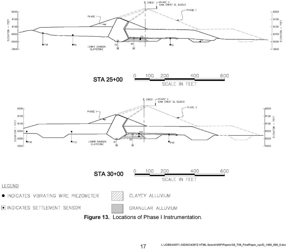
15 Vertical deformation of the foundation was estimated using one-dimensional analysis and two-dimensional linear elastic finite-element modeling techniques. One-dimensional analyses were completed using Terzaghi s one-dimensional theory of consolidation. Twodimensional analysis was performed using the SIGMA/W module of the GeoStudio 2004 software package. The analyses for the embankment were completed under maximum sections (STA and STA 30+00) of the embankment and along the centerline of the outlet works, which crosses the embankment at about STA Analyses were performed at these locations because it would allow for direct comparison of predicted deformation and recorded deformation using instrumentation data that would be installed during Phase I. For the two-dimensional analysis under Phase II embankment loading, we considered that the foundation is saturated and the rate of settlement is controlled by consolidation, not elastic properties. Results of the predicted foundation deformation for the Phase I and Phase II embankment at the maximum section (STA 25+00), and along the outlet works are shown on Figures 11 and 12, respectively. Instrumentation and Surveying Data Instrumentation was included in the Phase I dam to monitor the behavior of the embankment, foundation, and appurtenant structures during construction and throughout the life of the project. The instrumentation was designed to monitor critical elements of the dam for use in evaluation of embankment performance and to provide an early warning of changing conditions that could impact the safety of the facility. The following instrumentation and monitoring was established to collect data related to bedrock deformation: Vibrating wire piezometers Settlement sensors Surveying of the outlet works conduit The general locations of the vibrating wire piezometers and settlement sensors in the valley section of the embankment are shown on Figure 13. Readings from the piezometers installed within the bedrock foundation were reviewed, but the data did not display expected behavior of the bedrock pore water pressures under loading. Therefore, the readings were not used for calibration of design parameters. Settlement instruments S1 and S2 are located below the core along the Phase I dam centerline and record settlement in bedrock. Instruments S3 and S4 are located about 100 feet downstream of the Phase I dam centerline and monitor settlement in the alluvial foundation soils and bedrock. The subsurface profile at sensor S3 consists of about 15 feet of clayey alluvium, underlain by 15 feet of granular alluvium, underlain by 45 feet of claystone. At sensor S4, the subsurface profile consists of about 23 feet of granular alluvium underlain by 52 feet of claystone. Data from Sensor S1 was not used because the data was considered not to be reliable. Data from these settlement sensors are shown on Figure

16 Figure 11. Total Initial Predicted Deformation at Maximum Section. Figure 12. Total Initial Predicted Deformation for Outlet Works Conduit. 16

17 Figure 13. Locations of Phase I Instrumentation. 17
18 Figure 14. Phase I Settlement Sensor Data. Calibration from Instrumentation To directly compare the data from the settlement sensors, a time-rate of consolidation analysis needed to be performed. Using the laboratory value of c v = 68 ft 2 /year, approximately 22 percent of the total deformation in the bedrock was estimated to occur at completion of the Phase I construction, which was a time length of about 24 months. This percentage of consolidation was then compared to the settlement readings taken at the end of Phase I construction. Predictions versus instrumentation readings generally correlated well and are presented in Table 3. Table 3. Comparison of Instrumentation to Predicted Settlement. End of Phase I Total Foundation Settlement Approximate Location Instrumentation Data (inches) (1) S2 Centerline Phase I Dam Crest (STA 25+00) S3 100 Feet Downstream of Phase I Dam Crest (STA 30+00) S4 100 Feet Downstream of Phase I Dam Crest (STA 25+00) Instrument Identification Notes: 1. Total recorded settlement at end of Phase I, includes bedrock and alluvium. 2. Total computed settlement in alluvium and 22 percent of total predicted consolidation settlement in bedrock. 1-D Analyses (inches) (2) 18

19 The predicted settlements from the one-dimensional analyses, using values for compression index (c c ), recompression index (c r ), and initial void ratio (e o ) for the claystone developed from laboratory data, correlated well with the recorded data from the settlement sensors. Monitoring results from the settlement sensors were additionally reviewed to calibrate a value of the Modulus of Elasticity. Based on the settlement at each sensor, initial and final stresses, and the previously described soil/rock thicknesses along the length of the sensors, we solved for E or c c using three equations. The computed E value from this analysis for claystone was 2.2 x 10 6 psf, which is higher than the E value computed using the laboratory testing of 3.5 x 10 5 psf. Calibration of E Based on Outlet Works Conduit Survey The vertical alignment of the outlet works conduit was surveyed during construction and the first post-construction survey was performed in July 2007, which was about 300 days after the end of the Phase I construction. The conduit alignment elevations were established to generally correspond to the maximum estimated foundation settlements and to provide a positive downstream slope along the entire conduit. The survey of the conduit was an optimal method to check construction elevations and to check the predicted deformation behavior of the foundation materials. The vertical alignment of the conduit based on the July 2007 survey, and the computed alignment of the conduit from the two-dimensional model from SIGMA/W using the laboratory value for E, were compared for the Phase I dam. Based on analyses completed for the embankment, consolidation of the claystone under Phase I loads was estimated to be about 30 percent complete at the time of the July 2007 survey. The survey data was then adjusted to represent total anticipated settlement (consolidation at 100 percent complete). These elevations are provided on Figure 15. The two-dimensional analysis of the outlet works conduit was re-computed varying the Modulus of Elasticity of the claystone bedrock in the finite-element model from the initial value of 3.5 x 10 5 psf until the predicted settlement profile for the Phase I embankment approximated the data from the adjusted July 2007 survey. We concluded that a modulus of elasticity in the claystone bedrock of 5.0 x 10 5 psf resulted in a predicted profile that most closely matched the survey data and was adopted for design. The computed two-dimensional vertical settlement of the outlet works conduit using and E of 5.0 x 10 5 psf and the survey data from July 2007 is presented on Figure 16. Final Analyses Final deformation analyses to support design of the Phase II dam and outlet works and to confirm adequacy of the outlet works components constructed during Phase I were completed using the adjusted Modulus of Elasticity of 5.0 x 10 5 psf. The computed maximum deformations for the Phase II dam below the maximum section of the embankment and along the outlet works for both the initial analyses and final analyses are presented on Figures 17 and 18, respectively. The revised deformations in the bedrock for the Phase II dam using the calibrated modulus values are generally about 25 percent less that originally predicted. The predicted deformations were used to a) compute the forces in the conduits to confirm that the previously constructed components were adequate for the applied loads, b) to design the additional 19

20 Phase II components of the outlet works, and c) to design the camber for the Phase II embankment. Design Features to Accommodate Settlement Total and long-term consolidation of the bedrock impacted design of both the embankment and outlet works. The following features were included in the design of the project to mitigate the impacts from deformation of the bedrock. The primary impact to design of the embankment was the amount of additional camber needed to accommodate bedrock settlement in addition to settlement of the embankment fill and foundation soils. Table 4 presents the required camber for the Phase II dam that was required based on the results of the initial and final deformation analyses. Table 4. Crest Elevations and Required Camber. Camber for Bedrock (2) Station Elevation Total Camber (inches) (1) Right Abutment Left Abutment Note: 1. Crest of dam slopes uniformly between identified stations. 2. Represents the amount of camber to compensate for bedrock consolidation. The magnitude and variable deformations of the foundation bedrock below the outlet works presented a greater design challenge than deformation below the embankment. The deformations along the conduit and between the conduit and the gate tower are not uniform because the gate tower is a relatively large (76 feet in the upstream/downstream direction) and is located at the downstream end of the flat upstream berm. The geometry of the embankment is not uniform because of the variation between the upstream and downstream slope and the downstream berm. Typically, the connection between the outlet conduits and the gate tower is designed as a rigid connection. One result of these variable deformations between the gate tower and conduits was that the use of this typical design connection concept would not be possible because the resulting moment from a rigid connection was extreme. The following elements were included in the design of the outlet works to accommodate expected short- and long-term deformation of the bedrock: The design elevation of the conduit included a non-uniform slope (camber) that was based on the computed deformations. The design slope was selected to maintain a positive downstream slope along the entire conduit for both the Phase I and Phase II dam. This camber should maintain the conduits in compression. The connection between the gate tower and conduits was designed as a pinned connection instead of a rigid connection. The connection was designed to allow axial movement of the joint and limited rotational movement. The joint was designed to allow up to 1.5 inches of lateral movement and up to 1 to 2 degrees of rotation. The joint detail is illustrated on Figure

21 Figure 15. Outlet Works Conduit Elevations and Survey Data. Figure 16. Comparison of Predicted Vertical Deformation for Phase I Outlet Works Conduit. 21
22 Figure 17. Predicted Phase II Embankment Deformation. Figure 18. Predicted Phase II Outlet Works Conduit Deformation. 22
23 Figure 19. Gate Tower and Conduit Connection. 23
24 Conclusions Evaluation of deformation is required to support design of any type of dam. However caution needs to be used when analyses are based on an assumption that deformation of bedrock does not need to be considered. This paper described deformation analyses that were completed to evaluate bedrock settlement to support design of a large earth dam and how settlement of the bedrock impacted design of the project. Similar types of bedrock exist in many parts of the United States and it is important early in the design of a new dam to identify what type of data is needed to investigate not only the strength but the deformation properties of the foundation bedrock. Typically large-scale field tests are not performed to support deformation analyses needed to design dams because of cost and other practical considerations to collect this data. Also it is rare for a dam to be designed to be enlarged and to include instrumentation and monitoring that is designed to collect data to allow calibration of the analyses models. We offer the following recommended guidelines related to development of material properties for a bedrock deformation analyses. The depth of influence can be estimated from the site investigation to help determine an incompressible boundary for computing deformation by finite element analysis, because stresses within the foundation rock from foundation loads tend to decrease with depth. In cases where the foundation consists of multi-layered rock masses, the depth of influence should be considered because each layer may have different elastic properties. Attention should be given to changes in intensity of fractures, weathering and values of RQD. Instrumentation data is not usually available during initial design stages, therefore laboratory data will likely be the initial or only method used to estimate material properties for predicting deformation. For development of consolidation properties of claystone bedrock, consolidation tests are a preferable method to obtain design values. Selecting the average value for the coefficient of compression or recompression and coefficient of consolidation yield good representative values for predicting deformation. A number of consolidation tests should be performed to have sufficient data for selection of a representative value. A good check of the value of coefficient of consolidation can be performed by comparison to settlement sensors installed within the bedrock. Although the vibrating wire piezometers installed for this project did not provide reasonable data within the bedrock, readings of dissipation of the excess pore water pressure from construction may additionally provide a calibration of c v. Using laboratory data for selecting a modulus of elasticity has proven to be more difficult. Depending on the method of estimation of modulus, the value will vary and most tests yield a wide range of values for selection. We offer the following observations and opinions for consideration of testing programs and selection of modulus of elasticity for similar geology: Perform a practical number of unconfined compression tests to establish an upper bound value and to evaluate the variability of the rock. Perform a number of triaxial compression tests. Derivation of modulus from triaxial tests may still yield an upper bound value, but the value should be closer to an appropriate design value and should compare reasonably to other test methods. This test can be compared to consolidation testing and help indicate outliers from the various test methods. 24
25 Perform a higher number of consolidation tests. The value of modulus derived from these tests is likely to be within the closest range to a representative design value. Using the 80 percent exceedance value appears to underestimate the average modulus of the claystone by about 30 percent, resulting in over predicting deformation by about 25 percent. However, without calibration of modulus from survey data or instrumentation, selecting the 70 to 80 percent exceedance value from this test method provides a reasonable conservative and practical value for design. Install monitoring instruments (when applicable) in the early stages of construction to review design assumptions and monitor deformation, because the time for weak claystone bedrock to achieve full consolidation will likely occur after construction of the project is complete. A reasonable investigation and testing program was executed; however, upon examining the deformation of soft bedrock, additional sampling and testing should have been performed within the compressible bedrock. Specifically additional consolidation testing should have been completed to provide more data for the selection of modulus of elasticity. The initial development of modulus provided a value that generated a safe and conservative design; however, using survey data to calibrate the modulus value resulted in a more valueengineered design. Bedrock settlement can be a significant issue for medium to large earth dams and the potential deformation of the bedrock should be evaluated early in design. References Bardet, Jean-Pierre (Bardet) (1997). Experimental Soil Mechanics. Prentice Hall, Upper Saddle River, NJ. Day, Robert W. (2006). Foundation Engineering Handbook (pp ). McGraw-Hill, New York, NY. Salgado, Rodrigo (2008). The Engineering of Foundations (p 285. McGraw-Hill, New York, NY. U.S. Army Corps of Engineers (USACE) (1994). Rock Foundations, EM , November
c. Borehole Shear Test (BST): BST is performed according to the instructions published by Handy Geotechnical Instruments, Inc.
: BST is performed according to the instructions published by Handy Geotechnical Instruments, Inc.") Design Manual Chapter 6 - Geotechnical 6B - Subsurface Exploration Program 6B-2 Testing A. General Information Several testing methods can be used to measure soil engineering properties. The advantages,
Design Manual Chapter 6 - Geotechnical 6B - Subsurface Exploration Program 6B-2 Testing A. General Information Several testing methods can be used to measure soil engineering properties. The advantages,
When to Use Immediate Settlement in Settle 3D
 When to Use Immediate Settlement in Settle 3D Most engineers agree that settlement is made up of three components: immediate, primary consolidation and secondary consolidation (or creep). Most engineers
ENCE 4610 Foundation Analysis and Design
 This image cannot currently be displayed. ENCE 4610 Foundation Analysis and Design Shallow Foundations Total and Differential Settlement Schmertmann s Method This image cannot currently be displayed. Strength
Consolidation and Settlement Analysis
 19 Consolidation and Settlement Analysis Patrick J. Fox Purdue University 19.1 Components of Total Settlement 19.2 Immediate Settlement 19.3 Consolidation Settlement Total Consolidation Settlement Rate
Period #16: Soil Compressibility and Consolidation (II)
") Period #16: Soil Compressibility and Consolidation (II) A. Review and Motivation (1) Review: In most soils, changes in total volume are associated with reductions in void volume. The volume change of the
Period #16: Soil Compressibility and Consolidation (II) A. Review and Motivation (1) Review: In most soils, changes in total volume are associated with reductions in void volume. The volume change of the
CIVL451. Soil Exploration and Characterization
 CIVL451 Soil Exploration and Characterization 1 Definition The process of determining the layers of natural soil deposits that will underlie a proposed structure and their physical properties is generally
How To Prepare A Geotechnical Study For A Trunk Sewer Project In Lincoln, Nebraska
 APPENDIX B Geotechnical Engineering Report GEOTECHNICAL ENGINEERING REPORT Preliminary Geotechnical Study Upper Southeast Salt Creek Sanitary Trunk Sewer Lincoln Wastewater System Lincoln, Nebraska PREPARED
STRUCTURES. 1.1. Excavation and backfill for structures should conform to the topic EXCAVATION AND BACKFILL.
 STRUCTURES 1. General. Critical structures may impact the integrity of a flood control project in several manners such as the excavation for construction of the structure, the type of foundation, backfill
INTRODUCTION TO SOIL MODULI. Jean-Louis BRIAUD 1
 INTRODUCTION TO SOIL MODULI By Jean-Louis BRIAUD 1 The modulus of a soil is one of the most difficult soil parameters to estimate because it depends on so many factors. Therefore when one says for example:
Table of Contents 10.1 GENERAL... 10.1-1
 Table of Contents Section Page 10.1 GENERAL... 10.1-1 10.1.1 Overview... 10.1-1 10.1.2 Role of Uncertainty in Property Interpretation... 10.1-1 10.1.3 Role of Drainage in Property Interpretation... 10.1-2
Soil Mechanics. Soil Mechanics
 Soil is the most misunderstood term in the field. The problem arises in the reasons for which different groups or professions study soils. Soil scientists are interested in soils as a medium for plant
Strength Determination of "Tooth-Paste" Like Sand and Gravel Washing Fines Using DMT
 Strength Determination of "Tooth-Paste" Like Sand and Gravel Washing Fines Using DMT David L. Knott, P.E. and James M. Sheahan, P.E. HDR Engineering, Inc. 3 Gateway Center Pittsburgh, PA 15222-1074 Phone:
Moving Small Mountains Vesuvius Dam Rehab
 Moving Small Mountains Vesuvius Dam Rehab Susan L. Peterson, P.E., regional dams engineer, Eastern Region, Bedford, IN Note: The following article, Moving Small Mountains Vesuvius Dam Rehab, by Sue Peterson,
Figure 2.31. CPT Equipment
 Soil tests (1) In-situ test In order to sound the strength of the soils in Las Colinas Mountain, portable cone penetration tests (Japan Geotechnical Society, 1995) were performed at three points C1-C3
Estimation of Compression Properties of Clayey Soils Salt Lake Valley, Utah
 Estimation of Compression Properties of Clayey Soils Salt Lake Valley, Utah Report Prepared for the Utah Department of Transportation Research Division by Steven F. Bartlett, PhD. P.E. Assistant Professor
4.3 Results... 27 4.3.1 Drained Conditions... 27 4.3.2 Undrained Conditions... 28 4.4 References... 30 4.5 Data Files... 30 5 Undrained Analysis of
 Table of Contents 1 One Dimensional Compression of a Finite Layer... 3 1.1 Problem Description... 3 1.1.1 Uniform Mesh... 3 1.1.2 Graded Mesh... 5 1.2 Analytical Solution... 6 1.3 Results... 6 1.3.1 Uniform
Design, Testing and Automated Monitoring of ACIP Piles in Residual Soils
 Design, Testing and Automated Monitoring of ACIP Piles in Residual Soils Stephen W. Lacz 1, M. ASCE, P.E. and Richard C. Wells 2, F. ASCE, P.E. 1 Senior Professional, Trigon Kleinfelder, Inc., 313 Gallimore
Washington 98102-3699, mike.bailey@hartcrowser.com
 LESSONS LEARNED FROM A STONE COLUMN TEST PROGRAM IN GLACIAL DEPOSITS Barry S. Chen 1, P.E., Member, Geo-Institute and Michael J. Bailey 2, P.E., Member, Geo-Institute ABSTRACT A stone column test program
Drained and Undrained Conditions. Undrained and Drained Shear Strength
 Drained and Undrained Conditions Undrained and Drained Shear Strength Lecture No. October, 00 Drained condition occurs when there is no change in pore water pressure due to external loading. In a drained
NUMERICAL ANALYSIS OF SEEPAGE THROUGH EMBANKMENT DAMS (CASE STUDY: KOCHARY DAM, GOLPAYEGAN)
") NUMERICAL ANALYSIS OF SEEPAGE THROUGH EMBANKMENT DAMS (CASE STUDY: KOCHARY DAM, GOLPAYEGAN) *Reza Naghmehkhan Dahande 1 and Ahmad Taheri 2 1 Department of Civil Engineering-Water Management, Islamic Azad
NUMERICAL ANALYSIS OF SEEPAGE THROUGH EMBANKMENT DAMS (CASE STUDY: KOCHARY DAM, GOLPAYEGAN) *Reza Naghmehkhan Dahande 1 and Ahmad Taheri 2 1 Department of Civil Engineering-Water Management, Islamic Azad
Evaluation of Open Channel Flow Equations. Introduction :
 Evaluation of Open Channel Flow Equations Introduction : Most common hydraulic equations for open channels relate the section averaged mean velocity (V) to hydraulic radius (R) and hydraulic gradient (S).
Numerical Analysis of Texas Cone Penetration Test
 International Journal of Applied Science and Technology Vol. 2 No. 3; March 2012 Numerical Analysis of Texas Cone Penetration Test Nutan Palla Project Engineer, Tolunay-Wong Engineers, Inc. 10710 S Sam
CHAPTER 9 FEM MODELING OF SOIL-SHEET PILE WALL INTERACTION
 391 CHAPTER 9 FEM MODELING OF SOIL-SHEET PILE WALL INTERACTION 9.1 OVERVIEW OF FE SOIL-STRUCTURE INTERACTION Clough and Denby (1969) introduced Finite Element analysis into the soil-structure interaction
COMPENDIUM OF INDIAN STANDARDS ON SOIL ENGINEERING PART 2
 (PREVIEW) SP 36 (Part 2) : 1988 COMPENDIUM OF INDIAN STANDARDS ON SOIL ENGINEERING PART 2 IS 1893 : 1979 (Reaffirmed 1987) CODE OF PRACTICE FOR SUBSURFACE INVESTIGATION FOR FOUNDATIONS 1.1 This code deals
PILE FOUNDATIONS FM 5-134
 C H A P T E R 6 PILE FOUNDATIONS Section I. GROUP BEHAVIOR 6-1. Group action. Piles are most effective when combined in groups or clusters. Combining piles in a group complicates analysis since the characteristics
Settlement of Precast Culverts Under High Fills; The Influence of Construction Sequence and Structural Effects of Longitudinal Strains
 Settlement of Precast Culverts Under High Fills; The Influence of Construction Sequence and Structural Effects of Longitudinal Strains Doug Jenkins 1, Chris Lawson 2 1 Interactive Design Services, 2 Reinforced
1 Mobilisation and demobilisation 1 Deep boring sum 2 Cone penetration tests sum 3 Miscellenous tests sum
 Malaysian Civil Engineering Standard Method of Measurement (MyCESMM) CLASS D: SITE INVESTIGATION WORK Measurement covered under other classes: Excavation not carried out for the purpose of soil investigation
Outlet stabilization structure
 Overview of Sedimentation and Erosion Control Practices Practice no. 6.41 Outlet stabilization structure Erosion at the outlet of channels, culverts, and other structures is common, and can cause structural
Program COLANY Stone Columns Settlement Analysis. User Manual
 User Manual 1 CONTENTS SYNOPSIS 3 1. INTRODUCTION 4 2. PROBLEM DEFINITION 4 2.1 Material Properties 2.2 Dimensions 2.3 Units 6 7 7 3. EXAMPLE PROBLEM 8 3.1 Description 3.2 Hand Calculation 8 8 4. COLANY
ANNEX D1 BASIC CONSIDERATIONS FOR REVIEWING STUDIES IN THE DETAILED RISK ASSESSMENT FOR SAFETY
 ANNEX D1 BASIC CONSIDERATIONS FOR REVIEWING STUDIES IN THE DETAILED RISK ASSESSMENT FOR SAFETY ANNEX D1: BASIC CONSIDERATIONS FOR REVIEWING STUDIES IN DRA FOR SAFETY D1-1 ANNEX D1 BASIC CONSIDERATIONS
CHAPTER 9 CHANNELS APPENDIX A. Hydraulic Design Equations for Open Channel Flow
 CHAPTER 9 CHANNELS APPENDIX A Hydraulic Design Equations for Open Channel Flow SEPTEMBER 2009 CHAPTER 9 APPENDIX A Hydraulic Design Equations for Open Channel Flow Introduction The Equations presented
CHAPTER 6 SETTLEMENT ANALYSES
 CHAPTER 6 SETTLEMENT ANALYSES This chapter provides information to use when analyzing the potential for failure due to settlement at an Ohio waste containment facility. It is important to account for settlement
Safe & Sound Bridge Terminology
 Safe & Sound Bridge Terminology Abutment A retaining wall supporting the ends of a bridge, and, in general, retaining or supporting the approach embankment. Approach The part of the bridge that carries
Eurocode 7 - Geotechnical design - Part 2 Ground investigation and testing
 Brussels, 18-20 February 2008 Dissemination of information workshop 1 Eurocode 7 - Geotechnical design - Part 2 Ground investigation and testing Dr.-Ing. Bernd Schuppener, Federal Waterways Engineering
Validation of Cable Bolt Support Design in Weak Rock Using SMART Instruments and Phase 2
 Validation of Cable Bolt Support Design in Weak Rock Using SMART Instruments and Phase 2 W.F. Bawden, Chair Lassonde Mineral Engineering Program, U. of Toronto, Canada J.D. Tod, Senior Engineer, Mine Design
Open Channel Flow 2F-2. A. Introduction. B. Definitions. Design Manual Chapter 2 - Stormwater 2F - Open Channel Flow
 Design Manual Chapter 2 - Stormwater 2F - Open Channel Flow 2F-2 Open Channel Flow A. Introduction The beginning of any channel design or modification is to understand the hydraulics of the stream. The
CITY UTILITIES DESIGN STANDARDS MANUAL
 CITY UTILITIES DESIGN STANDARDS MANUAL Book 2 (SW) SW9 June 2015 SW9.01 Purpose This Chapter provides information for the design of open channels for the conveyance of stormwater in the City of Fort Wayne.
Prattsville Berm Removal Project. 1.0 Project Location
 Prattsville Berm Removal Project 1.0 Project Location The project site is located between the New York State Route 23 Bridge over the Schoharie Creek and the Schoharie Reservoir. The restoration plan encompassed
FUNDAMENTALS OF CONSOLIDATION
 FUNDAMENTALS OF CONSOLIDATION SAND (Vertical Stress Increase) CLAY CONSOLIDATION: Volume change in saturated soils caused by the expulsion of pore water from loading. Saturated Soils: causes u to increase
Jackson Gulch Outlet Canal Rehabilitation Project
 Jackson Gulch Outlet Canal Rehabilitation Project Preliminary Budgetary Estimate for Rehabilitation February 2004 Prepared for the Mancos Water Conservancy District Jackson Gulch Reservoir 42888 County
Numerical Simulation of CPT Tip Resistance in Layered Soil
 Numerical Simulation of CPT Tip Resistance in Layered Soil M.M. Ahmadi, Assistant Professor, mmahmadi@sharif.edu Dept. of Civil Engineering, Sharif University of Technology, Tehran, Iran Abstract The paper
Emergency Spillways (Sediment basins)
") Emergency Spillways (Sediment basins) DRAINAGE CONTROL TECHNIQUE Low Gradient Velocity Control Short-Term Steep Gradient Channel Lining Medium-Long Term Outlet Control Soil Treatment Permanent [1] [1]
Emergency Spillways (Sediment basins) DRAINAGE CONTROL TECHNIQUE Low Gradient Velocity Control Short-Term Steep Gradient Channel Lining Medium-Long Term Outlet Control Soil Treatment Permanent [1] [1]
CHAPTER 9 LONG TERM MONITORING AT THE ROUTE 351 BRIDGE
 CHAPTER 9 LONG TERM MONITORING AT THE ROUTE 351 BRIDGE 9.1 INTRODUCTION An important reason that composite piles have not gained wide acceptance in the civil engineering practice is the lack of a long
Laterally Loaded Piles
 Laterally Loaded Piles 1 Soil Response Modelled by p-y Curves In order to properly analyze a laterally loaded pile foundation in soil/rock, a nonlinear relationship needs to be applied that provides soil
Module 1 : Site Exploration and Geotechnical Investigation. Lecture 4 : In-situ tests [ Section 4.1: Penetrometer Tests ] Objectives
![Module 1 : Site Exploration and Geotechnical Investigation. Lecture 4 : In-situ tests [ Section 4.1: Penetrometer Tests ] Objectives](/thumbs/26/8734290.jpg "Module 1 : Site Exploration and Geotechnical Investigation. Lecture 4 : In-situ tests [ Section 4.1: Penetrometer Tests ] Objectives") Lecture 4 : In-situ tests [ Section 4.1: Penetrometer Tests ] Objectives In this section you will learn the following Penetrometer Tests Standard penetration test Static cone penetration test Dynamic cone
Lecture 4 : In-situ tests [ Section 4.1: Penetrometer Tests ] Objectives In this section you will learn the following Penetrometer Tests Standard penetration test Static cone penetration test Dynamic cone
Topic 8: Open Channel Flow
 3.1 Course Number: CE 365K Course Title: Hydraulic Engineering Design Course Instructor: R.J. Charbeneau Subject: Open Channel Hydraulics Topics Covered: 8. Open Channel Flow and Manning Equation 9. Energy,
SAMPLE GUIDE SPECIFICATIONS FOR OSTERBERG CELL LOAD TESTING OF DEEP FOUNDATIONS
 Page 1 of 9 SAMPLE GUIDE SPECIFICATIONS FOR OSTERBERG CELL LOAD TESTING OF DEEP FOUNDATIONS 1. GENERAL REQUIREMENTS 1. Description of Work: This work consists of furnishing all materials, equipment and
KWANG SING ENGINEERING PTE LTD
 KWANG SING ENGINEERING PTE LTD 1. INTRODUCTION This report represents the soil investigation works at Aljunied Road / Geylang East Central. The objective of the soil investigation is to obtain soil parameters
Dams and Extreme Events Reducing Risk of Aging Infrastructure under Extreme Loading Conditions
 Dams and Extreme Events Reducing Risk of Aging Infrastructure under Extreme Loading Conditions 34th Annual USSD Conference San Francisco, California, April 7-11, 2014 Hosted by San Francisco Public Utilities
NOTES on the CONE PENETROMETER TEST
 GE 441 Advanced Engineering Geology & Geotechnics Spring 2004 Introduction NOTES on the CONE PENETROMETER TEST The standardized cone-penetrometer test (CPT) involves pushing a 1.41-inch diameter 55 o to
7.2.4 Seismic velocity, attenuation and rock properties
 7.2.4 Seismic velocity, attenuation and rock properties Rock properties that affect seismic velocity Porosity Lithification Pressure Fluid saturation Velocity in unconsolidated near surface soils (the
CLIFTY CREEK PLANT MADISON, INDIANA
 2015 DAM AND DIKE INSPECTION REPORT GERS-15-018 CLIFTY CREEK PLANT MADISON, INDIANA PREPARED BY GEOTECHNICAL ENGINEERING AEP SERVICE CORPORATION 1 RIVERSIDE PLAZA COLUMBUS, OHIO Annual Dam and Dike Inspection
ESTIMATION OF UNDRAINED SETTLEMENT OF SHALLOW FOUNDATIONS ON LONDON CLAY
 International Conference on Structural and Foundation Failures August 2-4, 2004, Singapore ESTIMATION OF UNDRAINED SETTLEMENT OF SHALLOW FOUNDATIONS ON LONDON CLAY A. S. Osman, H.C. Yeow and M.D. Bolton
REPORT OF GEOTECHNICAL EXPLORATION BRIDGE STRUCTURE REPORT
 REPORT OF GEOTECHNICAL EXPLORATION BRIDGE STRUCTURE REPORT New Wolf Pen Branch Road Bridge and Temporary Diversion Bridge LSIORBP Section 4 KY 841 Louisville, Jefferson County, Kentucky KSWA Project No.
Appendix 4-C. Open Channel Theory
 4-C-1 Appendix 4-C Open Channel Theory 4-C-2 Appendix 4.C - Table of Contents 4.C.1 Open Channel Flow Theory 4-C-3 4.C.2 Concepts 4-C-3 4.C.2.1 Specific Energy 4-C-3 4.C.2.2 Velocity Distribution Coefficient
FAILURE OF TETON DAM
 BACKGROUND ON FAILURE OF TETON DAM Near Rexburg, Idaho June 5, 1976 J. David Rogers, Ph.D., P.E., R.G. Karl F. Hasselmann Chair in Geological Engineering Department of Geological Sciences & Engineering
NJ650.1404 Interception Drainage
 NJ650.1404 Interception Drainage Interception drainage is used to intercept surface and subsurface water. The investigation, planning, and construction of surface interception drains follow the requirements
A Ground Improvement Update from TerraSystems
 TERRANOTES A Ground Improvement Update from TerraSystems SOIL MODULUS AFTER GROUND IMPROVEMENT Evaluation of ground improvement is accomplished using a variety of methods, from simple elevation surveys
APPENDIX G SETTLEMENT
 APPENDIX G SETTLEMENT TABLE OF CONTENTS G.1 IN T R O D U C T IO N... 1 G.2 MATERIAL PLACEMENT AND COMPACTION... 1 G.2.1 Incom pressible M aterials... 1 G.2.2 Compressible Materials... 2 G.2.3 Soil P lacem
Numerical Analysis of the Moving Formwork Bracket Stress during Construction of a Curved Continuous Box Girder Bridge with Variable Width
 Modern Applied Science; Vol. 9, No. 6; 2015 ISSN 1913-1844 E-ISSN 1913-1852 Published by Canadian Center of Science and Education Numerical Analysis of the Moving Formwork Bracket Stress during Construction
GEOTECHNICAL DESIGN MANUAL
 GEOTECHNICAL DESIGN MANUAL CHAPTER 6 ENGINEERING PROPERTIES OF SOIL AND ROCK NYSDOT Geotechnical Page 6-1 June 17, 2013 (Intentionally left blank) NYSDOT Geotechnical Page 6-2 June 17, 2013 Table of Contents
EXHIBIT A SCOPE OF WORK Montgomery Reservoir Improvements
 EXHIBIT A SCOPE OF WORK Montgomery Reservoir Improvements 1.0 INTRODUCTION Colorado Springs Utilities (Utilities) is requesting proposals to provide final engineering, design, and construction management
CE 366 SETTLEMENT (Problems & Solutions)
") CE 366 SETTLEMENT (Problems & Solutions) P. 1) LOAD UNDER A RECTANGULAR AREA (1) Question: The footing shown in the figure below exerts a uniform pressure of 300 kn/m 2 to the soil. Determine vertical
CE 366 SETTLEMENT (Problems & Solutions) P. 1) LOAD UNDER A RECTANGULAR AREA (1) Question: The footing shown in the figure below exerts a uniform pressure of 300 kn/m 2 to the soil. Determine vertical
FOUNDATION DESIGN. Instructional Materials Complementing FEMA 451, Design Examples
 FOUNDATION DESIGN Proportioning elements for: Transfer of seismic forces Strength and stiffness Shallow and deep foundations Elastic and plastic analysis Foundation Design 14-1 Load Path and Transfer to
Advanced Natural Gas Storage (ANGAS) Project and Verification Tests of Experimental Lined Rock Cavern in Japan
 Project and Verification Tests of Experimental Lined Rock Cavern in Japan") Advanced Natural Gas Storage (ANGAS) Project and Verification Tests of Experimental Lined Rock Cavern in Japan Toru Komatsubara THE JAPAN GAS ASSOCIATION Taku Watanabe TOKYO GAS CO.,LTD. Satoshi Murase
Advanced Natural Gas Storage (ANGAS) Project and Verification Tests of Experimental Lined Rock Cavern in Japan Toru Komatsubara THE JAPAN GAS ASSOCIATION Taku Watanabe TOKYO GAS CO.,LTD. Satoshi Murase
How To Design A Foundation
 The Islamic university - Gaza Faculty of Engineering Civil Engineering Department CHAPTER (2) SITE INVESTIGATION Instructor : Dr. Jehad Hamad Definition The process of determining the layers of natural
SPECIFICATION FOR DYNAMIC CONSOLIDATION / DYNAMIC REPLACEMENT
 SPECIFICATION FOR DYNAMIC CONSOLIDATION / DYNAMIC REPLACEMENT 1.0 SOIL IMPROVEMENT 1.1 General Soil Investigation Information are provided in Part B1 annex as a guide to the Contractor for his consideration
METHODS FOR ACHIEVEMENT UNIFORM STRESSES DISTRIBUTION UNDER THE FOUNDATION
 International Journal of Civil Engineering and Technology (IJCIET) Volume 7, Issue 2, March-April 2016, pp. 45-66, Article ID: IJCIET_07_02_004 Available online at http://www.iaeme.com/ijciet/issues.asp?jtype=ijciet&vtype=7&itype=2
Appendix A Sub surface displacements around excavations Data presented in Xdisp sample file
 Appendix A Sub surface displacements around excavations Data presented in Xdisp sample file Notation B1 = lowest level of basement slab c = cohesion E = drained Young s Modulus Eu = undrained Young s Modulus
INDIRECT METHODS SOUNDING OR PENETRATION TESTS. Dr. K. M. Kouzer, Associate Professor in Civil Engineering, GEC Kozhikode
 INDIRECT METHODS SOUNDING OR PENETRATION TESTS STANDARD PENETRATION TEST (SPT) Reference can be made to IS 2131 1981 for details on SPT. It is a field edtest to estimate e the penetration e resistance
Fundamentals of CONE PENETROMETER TEST (CPT) SOUNDINGS. J. David Rogers, Ph.D., P.E., R.G.
 SOUNDINGS. J. David Rogers, Ph.D., P.E., R.G.") Fundamentals of CONE PENETROMETER TEST (CPT) SOUNDINGS J. David Rogers, Ph.D., P.E., R.G. Cone Penetration Test CPT soundings can be very effective in site characterization, especially sites with discrete
Fundamentals of CONE PENETROMETER TEST (CPT) SOUNDINGS J. David Rogers, Ph.D., P.E., R.G. Cone Penetration Test CPT soundings can be very effective in site characterization, especially sites with discrete
Abstract. Introduction
 SEISMIC REFRACTION INTERPRETATION WITH VELOCITY GRADIENT AND DEPTH OF INVESTIGATION Michael L. Rucker AMEC Earth & Environmental, Inc. Phoenix, Arizona; michael.rucker@amec.com Abstract Traditional interpretation
Cone Penetration Testing (CPT) Michael Bailey, P.G. U.S. Army Corps of Engineers, Savannah District
 Michael Bailey, P.G. U.S. Army Corps of Engineers, Savannah District") Cone Penetration Testing (CPT) Michael Bailey, P.G. U.S. Army Corps of Engineers, Savannah District Recommended publications ASTM D 5778-07 Standard Test Method for Electronic Friction Cone and Piezocone
Cone Penetration Testing (CPT) Michael Bailey, P.G. U.S. Army Corps of Engineers, Savannah District Recommended publications ASTM D 5778-07 Standard Test Method for Electronic Friction Cone and Piezocone
A Theoretical Solution for Consolidation Rates of Stone Column-Reinforced Foundations Accounting for Smear and Well Resistance Effects
 The International Journal of Geomechanics Volume, Number, 135 151 (00) A Theoretical Solution for Consolidation Rates of Stone Column-Reinforced Foundations Accounting for Smear and Well Resistance Effects
Outline MICROPILES SUBJECT TO LATERAL LOADING. Dr. Jesús Gómez, P.E.
 MICROPILES SUBJECT TO LATERAL LOADING Dr. Jesús Gómez, P.E. Micropile Design and Construction Seminar Las Vegas, NV April 3-4, 2008 Outline When are micropiles subject to lateral load? How do we analyze
CONSTANT HEAD AND FALLING HEAD PERMEABILITY TEST
 CONSTANT HEAD AND FALLING HEAD PERMEABILITY TEST 1 Permeability is a measure of the ease in which water can flow through a soil volume. It is one of the most important geotechnical parameters. However,
Geotechnical Investigation using Standard Penetration Test (SPT) in Rangamati, Bandarban and Khagrachari Towns
 in Rangamati, Bandarban and Khagrachari Towns") 1. Introduction 1.1 Scope of Work The Asian Disaster Preparedness Centre (ADPC) is implementing the project Seismic Hazard and Vulnerability Mapping for Rangamati, Bandarban and Khagrachari Municipality.
1. Introduction 1.1 Scope of Work The Asian Disaster Preparedness Centre (ADPC) is implementing the project Seismic Hazard and Vulnerability Mapping for Rangamati, Bandarban and Khagrachari Municipality.
Secondary Consolidation and the effect of Surcharge Load
 Secondary Consolidation and the effect of Surcharge Load Thuvaragasingam Bagavasingam University of Moratuwa Colombo, Sri Lanka International Journal of Engineering Research & Technology (IJERT) Abstract
Ohio Department of Transportation Division of Production Management Office of Geotechnical Engineering. Geotechnical Bulletin PLAN SUBGRADES
 Ohio Department of Transportation Division of Production Management Office of Geotechnical Engineering Geotechnical Bulletin GB 1 PLAN SUBGRADES Geotechnical Bulletin GB1 was jointly developed by the Offices
Investigation of Foundation Failure. Step 1 - Data Collection. Investigation Steps
 Foundations on Expansive Clay Soil Part 3 - Investigation of Failed Foundations Presented by: Eric Green, P.E. Structural Engineer Slide 1 Copyright Eric Green 2005 Investigation of Foundation Failure
INTERNATIONAL JOURNAL OF CIVIL AND STRUCTURAL ENGINEERING Volume 3, No 3, 2013
 INTERNATIONAL JOURNAL OF CIVIL AND STRUCTURAL ENGINEERING Volume 3, No 3, 2013 Copyright by the authors - Licensee IPA- Under Creative Commons license 3.0 Research article ISSN 0976 4399 Reliability of
Estimation of Adjacent Building Settlement During Drilling of Urban Tunnels
 Estimation of Adjacent Building During Drilling of Urban Tunnels Shahram Pourakbar 1, Mohammad Azadi 2, Bujang B. K. Huat 1, Afshin Asadi 1 1 Department of Civil Engineering, University Putra Malaysia
Dynamic Load Testing of Helical Piles
 Dynamic Load Testing of Helical Piles ANNUAL KANSAS CITY SPECIALTY SEMINAR 2014 JANUARY 10, 2014 Jorge Beim JWB Consulting LLC Pile Dynamics, Inc. Main Topics Brief description of the Dynamic Load Test
Impacts of Tunnelling on Ground and Groundwater and Control Measures Part 1: Estimation Methods
 Impacts of Tunnelling on Ground and Groundwater and Control Measures Part 1: Estimation Methods Steve Macklin Principal Engineering Geologist GHD Melbourne 1. Introduction, scope of Part 1 2. Terminology
Index. protection. excavated drop inlet protection (Temporary) 6.50.1 6.51.1. Block and gravel inlet Protection (Temporary) 6.52.1
 6.50.1 6.51.1. Block and gravel inlet Protection (Temporary) 6.52.1") 6 Index inlet protection excavated drop inlet protection (Temporary) 6.50.1 HARDWARE CLOTH AND GRAVEL INLET PROTECTION Block and gravel inlet Protection (Temporary) sod drop inlet protection ROCK DOUGHNUT
6 Index inlet protection excavated drop inlet protection (Temporary) 6.50.1 HARDWARE CLOTH AND GRAVEL INLET PROTECTION Block and gravel inlet Protection (Temporary) sod drop inlet protection ROCK DOUGHNUT
REINFORCED CONCRETE. Reinforced Concrete Design. A Fundamental Approach - Fifth Edition. Walls are generally used to provide lateral support for:
 HANDOUT REINFORCED CONCRETE Reinforced Concrete Design A Fundamental Approach - Fifth Edition RETAINING WALLS Fifth Edition A. J. Clark School of Engineering Department of Civil and Environmental Engineering
Flood mitigation program for Gatun lake. Programa de mitigación de inundaciones del lago Gatún
 Flood mitigation program for Gatun lake Programa de mitigación de inundaciones del lago Gatún Moffatt & Nichol Engineers 10 de febrero de 2005 Contrato No. 126161 Introducción y Recomendaciones 1 INTRODUCTION
DEM modelling of the dynamic penetration process on Mars as a part of the NASA InSight Mission
 Proceedings of the 4th European Young Geotechnical Engineers Conference (EYGEC), Durham, UK Osman, A.S. & Toll, D.G. (Eds.) 05 ISBN 978-0-9933836-0 DEM modelling of the dynamic penetration process on Mars
Basic Hydrology. Time of Concentration Methodology
 Basic Hydrology Time of Concentration Methodology By: Paul Schiariti, P.E., CPESC Mercer County Soil Conservation District What is the Time of Concentration? The time it takes for runoff to travel from
ANALYTICAL AND EXPERIMENTAL EVALUATION OF SPRING BACK EFFECTS IN A TYPICAL COLD ROLLED SHEET
 International Journal of Mechanical Engineering and Technology (IJMET) Volume 7, Issue 1, Jan-Feb 2016, pp. 119-130, Article ID: IJMET_07_01_013 Available online at http://www.iaeme.com/ijmet/issues.asp?jtype=ijmet&vtype=7&itype=1
US Army Corps of Engineers BUILDING STRONG
 Fort Worth District Public Meeting 20 August 2013 US Army Corps of Engineers Lewisville Dam - Authorization Authorized by the River and Harbor Act, approved 2 March 1945 (Public Law 14, 79th Congress,
GEOSYNTHETICS ENGINEERING: IN THEORY AND PRACTICE
 GEOSYNTHETICS ENGINEERING: IN THEORY AND PRACTICE Prof. J. N. Mandal Department of civil engineering, IIT Bombay, Powai, Mumbai 400076, India. Tel.022-25767328 email: cejnm@civil.iitb.ac.in Module - 4
Soil behaviour type from the CPT: an update
 Soil behaviour type from the CPT: an update P.K. Robertson Gregg Drilling & Testing Inc., Signal Hill, California, USA ABSTRACT: An initial application of CPT results is to evaluate soil type and soil
REAL-TIME SLOPE AND WALL MONITORING AND REPORTING USING 3-D MEMS-BASED, IN-PLACE INCLINOMETER SYSTEM
 REAL-TIME SLOPE AND WALL MONITORING AND REPORTING USING 3-D MEMS-BASED, IN-PLACE INCLINOMETER SYSTEM Aaron J. Muck, P.E., M.ASCE Swaminathan Srinivasan (Vasan), P.E., M.ASCE H.C. Nutting/Terracon Monitored
Open Channel Flow in Aquaculture
 SRAC Publication No. 74 Southern Regional Aquaculture Center March 1995 PR VI Open Channel Flow in Aquaculture J. David Bankston, Jr. 1 and Fred Eugene Baker Open channel flow of water has been used in
NORMALIZATION OF STRESS-STRAIN CURVES FROM CRS CONSOLIDATION TEST AND ITS APPLICATION TO CONSOLIDATION ANALYSIS
 LOWLAND TECHNOLOGY INTERNATIONAL Vol. 7, No. 1, 5-75, June 5 International Association of Lowland Technology (IALT), ISSN 13-95 NORMALIZATION OF STRESS-STRAIN CURVES FROM CRS CONSOLIDATION TEST AND ITS
Distribution Restriction Statement Approved for public release; distribution is unlimited.
 CECW-EG Engineer Manual 1110-1-1904 Department of the Army U.S. Army Corps of Engineers Washington, DC 20314-1000 Engineering and Design SETTLEMENT ANALYSIS EM 1110-1-1904 30 September 1990 Distribution
Equivalent CPT Method for Calculating Shallow Foundation Settlements in the Piedmont Residual Soils Based on the DMT Constrained Modulus Approach.
 Equivalent CPT Method for Calculating Shallow Foundation Settlements in the Piedmont Residual Soils Based on the DMT Constrained Modulus Approach. Paul W. Mayne, PhD, P.E., Professor, Geosystems Engineering
6.0 Results of Risk Analyses
 6. Results of Risk Analyses A risk analysis of the optimized embankment designs for the Salton Sea restoration project was conducted jointly by Kleinfelder and representatives from Reclamation. A risk
Caltrans Geotechnical Manual
 Cone Penetration Test The cone penetration test (CPT) is an in-situ sounding that pushes an electronic penetrometer into soil and records multiple measurements continuously with depth. Compared with rotary