Tubular Design and Downhole Equipment
|
|
|
- Sylvia Horton
- 10 years ago
- Views:
Transcription
1 Well Construction Basics How Wells are Designed & Constructed Minimum Expectations and Best Practices Assessing Completion Reliability and Risk Key Performance Indicators

2 Tubular Design and Downhole Equipment Casing is run to: prevent fill (formation fragments) from entering the wellbore protect fresh water zones from other fluids isolate zones - prevent or channel flow make drilling possible: mud weight has to stay in the window between a minimum that will control the pore pressure (and formation heaving) and a maximum that will not fracture the formation. Casing is also sometimes used where it is not needed.
 and a maximum that will not fracture the formation.")
3 Tubular String- 8 Design Factors Tension tube must stand its own weight in the running environment. Tubing must stand additional loads when pulling out or setting packers and forces due to temperature and pressure changes. Burst maintain integrity with high internal tubing pressures with little or no annular pressure support. Collapse - maintain integrity with high annulus pressures with little or no internal pressure support. Compression tube must stand compressive loads when setting some packers and in highly deviated wells or dog legs.

4 Tubular String- 8 Design Factors Couplings free from leaks, maintain ID clearance, strength through bend areas and in compression and tension loads. Corrosion - tube must be designed to counter corrosion reactions with flowing fluids over its lifetime. CO2, H2S, acid, cracking, etc. Abrasion/Erosion equipment must withstand abrasion and erosion loads over lifetime Stimulation Loads The tubular must withstand loads from acids, fracturing or other stimulations

5 surface P f = 0.6 P p = 0.43 psi/ft P f = 0.6 psi/ft shale P f = 0.65 P p = 0.33 psi/ft P f = 0.6 psi/ft shale P f = 0.8 P p = 0.65 psi/ft P f = 0.85 psi/ft

6 surface P f = 0.6 P p = 0.43 psi/ft P f = 0.6 psi/ft shale P f = 0.65 P p = 0.33 psi/ft P f = 0.6 psi/ft shale? P f = 0.8 P p = 0.65 psi/ft P f = 0.85 psi/ft

7 surface P f = 0.6 P p = 0.43 psi/ft P f = 0.6 psi/ft shale P f = 0.65 P p = 0.33 psi/ft P f = 0.6 psi/ft shale P f = 0.8 P p = 0.65 psi/ft P f = 0.85 psi/ft

8 surface P f = 0.6 P p = 0.43 psi/ft P f = 0.6 psi/ft shale P f = 0.65 P p = 0.33 psi/ft P f = 0.6 psi/ft shale P f = 0.8 P p = 0.65 psi/ft P f = 0.85 psi/ft

9 Since the conductor is often short and rarely cemented, it is not usually regarded as a pressure seal. Baku Suggest driving the 28 conductor into place. Drilling in may disturb sediments and aggravate sediment sides???

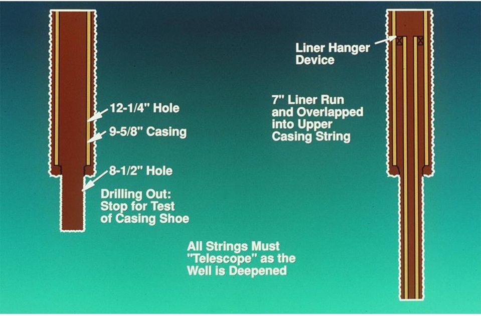
10 After the conductor is set, the bore hole is drilled to below the deepest fresh water source. The next smaller casing is run to bottom (maintaining minimum clearances), and this string is cemented. The BOP is commonly mounted on this string. Baku - Surface or protection string 20, usually drilled, but may be driven.

11 One or more production strings or liners are common for a well, depending on mud weight window and things like pipe sticking, reactive shales, and other problem areas. Baku Protection string /8 drilling wear can be a problem how to repair? Production string - 9-5/8, run to surface, but only partially cemented.

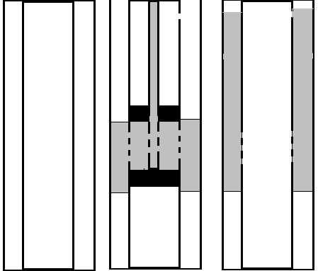
12 Critical points on liners are the seal at the top and cementing quality along the length.

13
14 Simple gas well wellhead, showing two master valves, a wing valve (leading to a choke unit) and a swab or lubricator access at the top.

15 This is one type of a well head flange. This unit slips on the top of the casing string and is welded to give a seal. The port in the side gives access to the annular area when tubing is run and hung off in the bowl in the top, inner part. The top is a flange with a seal groove that bolts to the wellhead or spool above.

16 Is every string cemented back to surface? No most times, it cannot be done in one operation. This is a very simple schematic - usually multiple casing strings and tubing are included in most cases, there are a minimum of two barriers unless leak potential is very low or there is no potential damage.

17 Casing Design Intent A annulus - tubing will collapse before casing bursts. B annulus production casing will collapse before surface casing will burst. C annulus usually cemented up, but watch any sealed area.


18 Well Design: 1. Tubing 2. Production Liner 3. Production Casing 4. Surface Casing 5. Conductor Pipe Details and Considerations: 1. Max press during production. 2. Max pressure during shut-in. 3. Max pressure during frac. 4. Packer fluid density & height. 5. Changes in well use? Gas lift source in the A annulus instead of packer fluid? 6. Effect of leaks 7. Annular pressure at start-up

19 1. Tubing and flow area below the tubing 2. A annulus tubing/production liner/production casing 3. B annulus production casing/surface casing annulus 4. C annulus surface casing/conductor

20 1. Tubing a. max production pressure b. max shut-in pressure c. max frac pressure 2. A annulus tubing/production liner/production casing a. initial design pkr fluid & no surf. press. b. start-up temp swing effect on press c. change in use to gas lift supply path? d. leak? 3. B annulus prod csg/surf. csg annulus a. initial design fluid packed annular press b. leak from high pressure A and add temp: 1. fluid packed 2. gas over fluid 4. C annulus surface casing/conductor a. cemented up or? b. leak?

 Backs up (increases) the collapse resistance of the production casing in the")
21 Special Case: How does changing the A annulus from brine to 2000 psi gas lift supply? Reduces the pressure at the shoe (removal of most of the hydrostatic column) Backs up (increases) the collapse resistance of the production casing in the B annulus. Must consider the effect of liquid packed vs. gas cushion.

22 Tubing: burst and collapse set by production, stimulation and kill forces. A annulus select to collapse the tubing before production casing will burst. Factors: 1. Liner top integrity 2. Is the shoe designed to leak? 3. What back-up force is provided by the tubing? 4. What back-up force is provided by the cement?
23 Casing collapse in a deep water environment occurred while running a 7 string at about 7500 of water. The automatic fill float valve failed and much of the string was only air filled when the pipe began to collapse. 17 joints collapsed in one run of the collapse across couplings!
24 Casing Grades API Grade Minimum Yield H-40 40,000 J-55 55,000 K-55 55,000 C-75 75,000 N-80 80,000 L-80 80,000 C-95 95,000 P ,000 Q ,000 V ,000
25 Casing Field Failure History 's 1980's 0.50 Failure Rate Connections Collapse Failure Mode Wear Brittle unknown Time Period 1990's Source Brian Schwind - PPI

26 Casing Design Options think about running and setting packers. Mixed weights, same grade Mixed grades and weights Monobore: mixed grades, same weight
27
28 Tubular Joints T&C Threaded and Coupled LT&C Long Thread and Coupled ST&C Short Thread and Coupled Integral direct connection using thread cut onto one pipe and a box and thread cut into another.
29 Threaded and Coupled Integral Connector Pin Pin Coupling or Connection Box Pin
30 EU or external upset strong connection, full opening, clearance problems IU or internal upset moderately strong connection, reduced opening, good external clearance NU or non-upset weak connection, full opening, good external clearance
31 Spotting Problems With Connections. What does it take? 1. Initial Thread Inspections 2. Torque/turn indicator and difference.. 3. Leak testing effective? Delta Turn BP 5-1/2" 20# Deltas 0.180? R 2 = Delta Torque
32 Why Cement? Completes the isolation step that was started with casing. Pressure isolation Pipe support and protection Exterior corrosion Pressure control Load and force application support Leakoff control prevents crossflow? Water influx control
33 Statistics Primary cementing cost about 5% of well cost. About 15% of primary cement jobs require squeezing Total cost of cementing when squeezing is required is about 17% of well cost. Typical number of squeezes required to fix a problem in a primary cement job = 3.
34 Cement Circulation Path: Down the casing and up the annulus Concerns: Cement density vs. pressure window from formation Cement bond between pipe and formation Cement pump time Ability to place the cement over the whole column (fluid loss control, correct volumes, pumpability) Cement strength development The quality and longevity of the seal.
35 Equivalent Circulating Density Cement is a viscous, dense fluid. The problems are in effective displacement of the mud and attaining a full column of uncontaminated cement. 16 ppg Friction Pressure 18 ppg effective mud weight?
36 The final slurry design has a certain slurry density, usually between 11 and 18 lb/gal, with typical class G or H being about 16.4 lb/gal. More water can be added, but the water will separate as it sets, resulting in channels or weak cement.
37 Fluid Density Balance used to get fluid density in lb/gal
38 General properties of cement slurries before additives. Note that without additives, the class G and H slurries would not be usable for many wells. Correct slurry design is critical for cement success.
39 Every cement design must take into account the temperature and pressure extremes in the well. Low temp retards the cement set time. High temp accelerates the cement set time.
40 Depth Geothermal gradient from an Alaska well through the permafrost. 100' Temperature -50F +10F 1850' +30F Geothermal 2.1F/100' 8900' TVD +200F
41 Modifying the Set Time of the Slurry Accelerators speed it up. calcium chloride sodium chloride gypsum Retarders slow it down lignins, sugars, cellulose some drilling muds sodium chloride The sodium chloride may be an accelerator or a retarder, depending on amount of salt and other factors. The effect of mud on the set time of cement is unpredictable.
42 Cement without a retarder in a hot formation will set up too rapidly; often before the cement has been completely displaced into the annulus. Increasing temperature makes the cement set up more quickly.
43 Cementing Problems That Must be Addressed in the Design 1. Well Control remember, until the cement sets, it must control the pore pressure like any other well control fluid. 2. Pumpability The pump time must be long enough to completely displace the cement from the pipe to the annulus. 3. Fluid Loss Control If the cement dehydrates, it can also shorten the set time. 4. Communication control (avoiding channels) 5. Invasion of natural fractures in the pay by cement.
44 Well Control Working in the slurry density window Pore pressure establishes the lower limit of slurry density. Fracturing gradient establishes the upper limit of slurry density. Cement density normally is 16.4 lb/gal Typical light weight cement is 11 to 12 lb/gal Heavier weight cements may be up to 23 lb/gal
45 Cement Problems and Failures Problems? Cement at shoe not strong enough to contain pressure of deeper zones must repair before drilling ahead. Casing not centralized leaves mud channel on low size. May leak now or later. Requires squeeze. Casing not moved during cementing you need to get mud displacement by cement to get a good job. Not enough cement in annulus to function as a barrier.

46 How far is cement brought up the annulus? Is the cement brought to surface? Unlikely. Why? 1. Fracture gradient is usually 0.7 psi/ft, cement density is 0.85 psi/ft. 2. Time 3. Cost 4. Not understanding protection need. Minimum 200 to 500 ft above the shoe
47 Common contaminants and ops that degrade cement bond? Slurry contamination primarily mud during displacement. Sulfate effects on mixing slurry and on set cement use sulfate resistant cement. Acids HCl no effect. HF significant local effect but shallow without channels. Explosives (perforating) usually minor effect if there are no channels. Typically, if a cement job breaks down after perforating, acidizing, solvent, or frac, the problem is that an existing mud channel in the cement has been disturbed.
48 Dehydration of the slurry causes a plug in the annulus. Since the first objective of a cement displacement is to remove the mud filtercake, the increased fluid loss has to be controlled by the cement slurry.
49 Fluid loss through wide natural fractures is often very hard to control requiring particulate and/or flake fluid loss control additives.
50 Low strength formations (low fracture gradient) pose a special problem. Created or natural fractures can be a thief zone for whole cement causing less height in the annulus. Natural fractures can also act as a fluid loss site for leakoff for water from the cement the result is dehydration of the cement slurry.
51 Salt zones can create cavities or washouts. If a salt water slurry is used, the salt must be checked with pumpability the salt can be an accelerator or a retarder.
52 Cement Displacement The first part of the cement slurry removes the mud cake and contaminates the cement. Contaminated cement will not set up. Where does the mud contamination come from? Mud system in the annulus Interior pipe walls Open hole filter cake Washouts and cavities Now, what can you do to prevent contamination?
53
54
55
56
57
58 Examples of equipment used on the BHA (bottom hole assembly) during casing running. The float equipment helps prevent backflow of cement after full displacement. The guide shoe helps guide the casing past ledges and doglegs (sudden hole direction changes) during pipe running.
59 Other Equipment Centralizers Scratchers Both help to improve the cement bond and seal between casing and formation.

60 Use of centralizers improve the ability of the cement to surround the pipe, displacing the mud and creating a channel-free seal. Centralizers also assist running casing in deviated sections. Area of undisplaced mud a mud channel remains, requiring squeezing.
61 Bow spring centralizer. This is a deformable, but very weak centralizer that looses value with increasing string weight and increasing wellbore deviation.
62 Straight vane casing centralizer. This is a slip-over type that floats between the couplings unless lock rings are added.
63 Spiral centralizer, assists in decreasing drag and helps centralize casing. It may also help channel cement in a short lived swirl pattern just downstream of the centralizer location. These are usually viewed as highly effective in improving cement isolation.
64 Squeeze Cementing Forces cement slurry, under pressure, through perforations or holes in the casing or liner.. Used to permanently block entry of undesirable fluids to the wellbore or to fill channels behind the casing. Water production form watered out zones or leaks are common targets. Also used to set cement packers to isolate sections of the annulus. The cement plug must remain an effective seal full temperature, highest pressure and in contact with any fluid from the well.
65 Repair Cementing Squeeze Cementing Shutting off watered-out perforation intervals Filling channels behind the pipe Covering pipe annuli that was never cemented Setting cement packers Partly copied from Arco Alaska presentation.
66 Treatment Execution Execution of squeeze cementing operations in four basic steps: Wellbore preparation Slurry mixing and pumping Squeeze Removal of excess cement
67 Squeeze Cementing channel repair Objectives 1. Locate the channel 2. Perforate into the channel 3. Inject cement and fill the channel Problems 1. locating the channel 2. squeezing into the channel
68 Channel Detection Cement bond log Noise log? - leaks Segmented or radial bond log Bond differences Looking for patterns that represent channels Block perforate and squeeze techniques
69 Squeeze Types Hesitation squeeze steady application of pressure thought by some to force cement in matrix may only help build size of dehydrated mass or node through fluid loss of liquid from the cement slurry. Actually what may be happening in some cases is that the wellbore is being restressed forming a stress cage by solids from mud or cement wedging into and bridging on the formation. This may allow 1 to 5 lb/gal higher fluid gradient weight than initial frac pressure of the formation.

70 Squeeze Types Suicide squeeze This squeeze perforates two spots high and low and squeezes from the bottom towards the top. There is a chance, if slurry volumes are too large, of cement spilling out of the upper perforations and sticking the isolation packer or retainer in the well.
71
72 Fluid Loss Control Excessive fluid loss in the slurry can result in bridging of tubulars by dehydrated cement. Slurries with too little fluid loss can result in insufficient buildup of filter cake on the formation (may also be a function of permeability and pressure). Fluid loss additives may be required to control fluid loss.
73 Cement Node Buildup Casing Formation Node with minimal intrusion into wellbore Primary cement sheath Arco
74 Rheology Controls Cement slurries have higher viscosity than most workover fluids and this significantly reduces maximum possible pump rate. Rheology and stability tests are commonly performed: At surface mixing temperatures, and At bottomhole static temperature BHST (caution make sure mix water temperature is not higher than bottom hole temp.). Slurries must stable to provide good rheology characteristics that are easily reproducible. Arco
75 Slurry Volume Volume of slurry prepared depends on: Length of perforated interval Capacity of liner/casing or channel behind pipe Void areas behind the perforations Force that can be applied to the tubing Configuration of surface mixing / pumping equipment Use of cement plugs, pigs or darts (isolation devices) Previous squeeze experience provides best guidelines.
76 Depth Control (with CT) In cement squeezing, surface equipment not accurate enough to position CT nozzle Downhole reference point is generally required Methods of setting depth reference Tagging bottom inaccurate in wells with fill, but viable in certain conditions Tagging completion restrictions tubing end locator (TEL) or tubing nipple locators (TNL) commonly used in squeeze cementing Arco
77 Cement Contamination Problems Contamination can result in: Unpredictable slurry characteristics Reduced compressive strength of the set cement Incorrect placement due to change in slurry volume To avoid contamination: Spacer fluid should isolate (ahead of/behind cement) Lines should be flushed each time a new fluid is pumped Mechanical separation of cement slurry using CT plugs (darts or pigs)
78 Reel Manifold Sampling Point and Flush Line Circulating pressure sensor To reel core and CT through reel isolation valve From pump unit Flush line to disposal Reel manifold valves Sample point Arco
79 Cement Composition and Vol. Low or high fluid loss? Depends on depth Volume of cement? depends on channel size Often try several small squeezes. Pressure?
80 Squeeze Success? Usually about 50% - but conditions make success vary widely. Increases when: circulation is possible through the channel, Isolation is used fro cement injection, cement blending is pod mix, the operator is experienced.
81 Cement Packer Can isolate the annulus Water control Tubing repair or isolation Stabilizing tubing prior to milling window Problems and considerations Floating the cement in the annulus there are ways! How long a cement column? - 50 to 300+ feet. Cement compositions for packers
82 Cement Packer Perforated annulus at or below point for packer. May need to perforate above top of packer when annulus is liquid filled. Displace cement from a straddle packer or packer and plug (or retainer) into the annulus.
83 Cement Placement With and Without Retaining Platform Stable cement column placed over the platform Cement slurry falls through less dense fluids Cement platform A retainer, mechanical plug, highly gelled mud pill (10 to 20 bbls) or a cement plug may be used as the platform.
84 Tool Selection Tool strings should generally be kept to a minimum Connector required on all jobs Check valves cannot be used with reverse circulation of excess cement Depth correlation tubing end or nipple locators are commonly used Plug catcher catch and retrieve plugs ahead/behind cement slurry Nozzles developed to improve the slurry placement
85 Cementing Nozzle Features Largediameter port Pins to retain ball within the nozzle Multiple smalldiameter radial ports Multiple smalldiameter radial ports Large diameter ports Arco
86 Monitoring Recording Parameters Coiled tubing Pressure, rate/volume, string weight, depth and tubing OD and tubing cycles. Pump unit Pressure, density and pump rate/volume Slurry batch mixer Monitor density and volume Other tankage Monitor density and volume Annulus Monitor volume and density of all fluids returned and pumped through the annulus. Record pressure.
87 Wellbore Preparation Filtered seawater or similar at high rate Choke open Wellbore clean and packed establish leakoff rate.
88 Laying In Cement Slurry Slurry pumped at maximum rate Choke open Wellbore pack fluid Spacer/fresh water Cement slurry Nozzle pulled up 50 ft below cement interface
89 Placing Thixotropic Slurries Slurry pumped at maximum rate/pressure allowed Choke closed, if wellbore not fluid packed, pump slowly down annulus to prevent U-tubing Wellbore pack fluid Cement slurry Wellbore pack fluid Nozzle placed above thief zone Highly gelled mud or other platform usually needed except in severe fluid loss.
90 Commencing Squeeze Low rate continuous pumping or hesitation Choke back returns monitoring pressure and volumes Wellbore pack fluid Spacer/fresh water Cement slurry Nozzle pulled up >50 ft above cement interface
91 Completing Squeeze Displacement fluid pumped at maximum rate/pressure allowed Choke back returns increasing final squeeze pressure Wellbore pack fluid Spacer/fresh water Nozzle moved continuously or frequently Cement slurry
92 Contaminating Excess Slurry Contaminant pumped at maximum rate/pressure Returns choked to maintain pressure on squeezed zone Contaminated slurry Cement slurry Nozzle penetrates slurry at a rate which provides a 50% mix of contaminant
93 Reverse Circulating Excess Slurry Fluid pumped at maximum rate/pressure for allowable differential (1500 psi) Open returns from CT Wellbore pack fluid Contaminated slurry Nozzle penetrates contaminated slurry at a rate which provides a 50% mix of contaminated slurry and pack fluid
94 Reverse Circulating Live Slurry Fluid pumped at maximum rate/pressure for allowable differential (1500 psi) Open returns from CT Wellbore pack fluid Nozzle penetrates slurry at a rate which provides a 50% mix Cement slurry
95 Wellbore Circulated Clean Fluid pumped at maximum rate/pressure Returns choked to maintain pressure on squeezed zone Wellbore pack fluid Nozzle reciprocated through treatment zone to TD Differential pressure maintained against squeezed zone
96 Wellbore Preparation Wellbore preparation operations include Slick-line work, e.g. fitting dummy gas-lift mandrels Pressure test the production tubing annulus Establish hang-up depth or TD using slick line Confirm and correlate depths with CT and flag the tubing Remove fill from rat hole below perforated interval Perform pretreatment perforation wash or acidizing Place a stable platform for cement slurry Ensure wellbore fully loaded with filtered water (or equivalent)
97 Slurry Mixing and Pumping Key points in the slurry mixing and pumping process include Batch mix and shear the slurry Conduct job-site quality control tests Prepare contaminant and spacer fluids as required Confirm CT depth Lay in cement slurry following pumping schedule When using thixotropic cements Do not stop pumping while cement is inside the work string Place CT nozzle above thief zone and pump down production tubing/ct annulus while squeezing the cement Overdisplace cement slurries out of the wellbore
98 Squeeze Downhole generation of filter cake aided by performing hesitation type squeezes For example, 10 min at 1000 psi, 15 min at 1500 psi, 20 min at 2000 psi... As fracture pressure exceeded Filter cake prevents formation from fracturing
99 Removal of Excess Cement Efficient removal of excess cement Critical to timely completion of job Achieved using several methods: Reverse circulation of live cement Circulation of contaminated cement Reverse circulation of contaminated cement
100 Reverse Circulation of Live Cement Reverse circulation of live cement slurry can be performed if Designed slurry thickening time (including safety factor) allows for completion of the reversing phase CT penetration rate controlled to effectively dilute the slurry as it is removed Maximum density of reversed fluid is 10 lb/gal Reversing is continued until clean returns observed at surface
101 Rev. Circulation of Contaminated Cement Contamination of excess cement is often necessary to: Extend slurry thickening time allows cleanout operations to be completed safely Allow cleanout operations to be delayed until cement nodes have increased compressive strength
102 Typical Cement Slurry Contaminant Composition TYPICAL CEMENT SLURRY CONTAMINANT COMPOSITION Borax/Bentonite 10 to 20 lb/bbl Bentonite 20 lb/bbl Borax 3 gal Cement Retarder Bio-Polymer Gel 1.5 lb/bbl Biozan gel
103 Circulation of Contaminated Cement Conventional circulation used when: Operating conditions cannot safely support reverse circulation of excess slurry Example: Operations performed through 1-1/4-in. work strings cannot employ reverse circulation techniques Reason: excessive friction pressure encountered
104 Evaluation of Squeeze Methods used to evaluate depend on treatment objectives Initial step in evaluation process Confirm condition of wellbore in the treatment zone If wellbore is obstructed Drilling/under-reaming may be required Additional check Ensure the rat hole is debris or cement free
105 Monitoring
106 Regulations
107 KPIs and Best Practices
108 References
109 Cement Displacement The first part of the cement slurry is contaminated by cement. Contaminated cement will not set up. Where does the mud contamination come from? Mud system in the annulus Interior pipe walls Open hole filter cake Washouts and cavities Now, what can you do to prevent contamination?
110 Basic Mud Cake Removal Physical scratchers, rotation, reciprocation Chemical dispersants, sweeps, solvents
111 Mechanical removal devices such as scratchers and scrapers require pipe movement, which is frequently not possible in high torque and drag instances. They also introduce easily breakable parts into the wellbore.
112 Chemical Flush Basics Displacement 1. Base fluid condition 2. Dispersant 3. Sweep 4. Spacer 5. Cement Mud Base fluid Dispersant Sweep A properly designed flush focuses on time of contact, fluid mixing, lift of solids and avoidance of cement contamination. Spacer Cement
113 Displacement and Pill Design must be designed to obtain effective mud displacement & water wetting of casing. Keys: disperse and thin the drilling fluid lift out debris and junk water wet pipe remove debris (mud cake, pipe dope, scale, etc.) effectively displace the mud allow uncontaminated cement to reach the desired height. Source: Wellcert
114 Brines for Mud Displacement 1. A thinning base fluid flush. 2. An effective brine transition system must further thin and strip the mud and create wellbore displacement. 3. A carrier spacer must sweep out the solids and clean any coating from the pipe or rock that could cause damage problems. 4. A separation spacer must do the final cleaning and separate the residual mud from the brine. 5. The brine must sweep the spacer out. At this point the well should be clean. Fluid loss may be high!
115 Cleaning and Transition Spacers 9-5/8 casing in 12-1/4 hole, annular area = 0.3 ft 2 Spacer Type Function Minimum Coverage WBM OBM Base Fluid Transition Thin & mud condition Mud to spacer, cuttings removal 250 to 500 ft Water Base oil 500 to 1000 Viscous pill Viscous Pill Wash Clean pipe 500 to 1500 Water+ WBM disp. surfactant Separation Completion Fluid Separate WS from brine, solids removal Completion fluid 500 to 1000 Viscous pill Pill? Fill Completion Fluid Oil + OBM disp. surfactant Completion Fluid
116 Brine Flush Contact Times 9-5/8 casing in 12-1/4 hole, annular area = 0.3 ft 2 For Pump Rate, bpm Annular Velocity, ft/min Barrels Pumped Column Length, ft Contact Time, minutes on one foot
117 Removal of the Mud Cake Part of the mud cake does not contribute to the fluid loss control. Removing these particles from the completion cleans the well. Approximately 80% of the outer layer of the cake can be removed in some muds without affecting fluid loss. Removal by velocity is often very effective. Even more effective with a dispersant. 300 ft/min or 92 m/min
 help!")
118 Flow profile in a well with decentralized pipe. Note That most of the flow comes along the top of the pipe. This affects cleanup and residence time of the fluid on the wellbore. The lower section of the wellbore may remain buried in cuttings and never have contact with any of the circulated fluids. Centralizing the pipe and rotating the pipe (reciprocating too) help! Major flow area Very low velocity or no movement
119 How can you tell if the entire hole is being circulated? Displacement marker sweeps. Dye, grain, colored beads, etc. Time their travel compare to calculated sweep. Marker arrival at near expected time, hole sweep is near ideal. Fast marker arrival at surface, entire hole is not being swept expect channels in the cement.

120 Displacement of the annulus to displace fluids and mud cake depends partly on velocity. The annulus changes as casing replaces the drill string. As the annular space decreases velocity for any rate increases in the smaller area and the back pressure on the bottom hole may also increase rates may have to decrease to avoid high ECD s (equivalent circulating densities). Circulating down the casing and up the small annulus can produce very high friction pressure and raised BHP.
121 Cement Displacement in the Pipe The Two-Plug displacement system Patented and used since about 1915
122
123 A single wiper plug dropping tool, showing bail release mechanism.

124 The Two Plug System Helps isolate the cement from the mud and the displacement fluid. The top plug is solid and the bottom plug is hollow and has a diaphragm that ruptures when the bottom plug hits the float collar. If the plugs are accidentally reversed, the cement will be trapped in the casing. The plugs are color coded to help prevent switching or help diagnose the problem when a plug is drilled out.

125 Every time a plug sweeps through the casing, a small amount of mud and other debris is pushed ahead of the plug. The contaminated cement in this area will not set or will set very slowly. For this reason, a float collar, set a joint above the shoe will keep the contaminated cement at the end of the displacement inside the casing not at the shoe. Mud Sheath Thickness (inch) 5 1/2 inch Casing 7 inch Casing 9 5/8 inch Casing 13 3/8 inch Casing 1/16 51 ft. 40 ft. 28 ft. 20 ft. 1/32 25 ft. 20 ft. 12 ft. 10 ft. 1/64 13 ft. 10 ft. 7 ft. 5 ft.
126
127 A float valve allows fill of the casing from the hole as the casing is run, but it must close after the cement has been pumped to prevent U-Tubing.
The Impact Of Cementing On Proper Well Control
 The Impact Of Cementing On Proper Well Control Lee Dillenbeck Senior Advisor, Cementing Chevron ETC Drilling and Completions 2010 Chevron Learning Objectives Explain the main reasons for cementing wells
Drilling Problems. pull
 Drilling Problems Pipe Sticking Lost Circulation Hole Deviation Pipe Failures Borehole Instability Mud Contamination Formation Damage Hole Cleaning H S General Equipment & Personnel Pipe Sticking Can not
WELL COMMANDER Versatile multi-cycle ball-activated drilling valve for mitigating downhole hazards
 WELL COMMANDER Versatile multi-cycle ball-activated drilling valve for mitigating downhole hazards Note: Operating instructions updated July 2014 WELL COMMANDER: Versatile multicycle ball-activated drilling
Energize your mind. www.halliburton.com April 2007. Lightweight Cement Meets Challenges of Weak Formations and Depleted Zones
 Energize your mind. www.halliburton.com April 2007 Lightweight Cement Meets Challenges of Weak Formations and Depleted Zones Today, operators are forced to drill in increasingly challenging environments
66 National Commission on the BP Deepwater Horizon Oil Spill and Offshore Drilling
 66 National Commission on the BP Deepwater Horizon Oil Spill and Offshore Drilling Chief Counsel s Report Chapter 4.3: Cement 67 Chapter 4.3 Cement Figure 4.3.1. Typical completed cement job. Well Cementing
Perforating Basics. How the perforating processes work. George E. King Engineering GEKEngineering.com 3/14/2009 1
 Perforating Basics How the perforating processes work 3/14/2009 1 Perforating Methods 1. The vast majority of all perforating work is performed with shaped charge or jet perforating charges. 2. Bullet
E-Line and Braided Line. E-Line Open Hole wireline
 E-Line and Braided Line E-Line Open Hole wireline Braided Line More strength Less feel Harder to seal Much harder to fish Braided line stronger (2800 to 3500 lb working strength, but less feel when fishing
Argentina Tataru*, Marcel Adrian Piteiu*, Dan-Paul Stefanescu*, Ioana Vlasin*
 WIERTNICTWO NAFTA GAZ TOM 24 ZESZYT 1 2007 Argentina Tataru*, Marcel Adrian Piteiu*, Dan-Paul Stefanescu*, Ioana Vlasin* NEW TECHNICAL CONSIDERATIONS OF ROMGAZ COMPANY REGARDING DRILLING, COMPLETION AND
An Introduction to Oil and Gas Well Servicing
 An Introduction to Oil and Gas Well Servicing Educational Material from the IOM 3 Oil and Gas Division The global network for the materials cycle Introduction The Institute of Materials, Minerals & Mining
DecisionSpace Well Engineering Software
 DATA SHEET DecisionSpace Well Engineering Software DecisionSpace Drilling & Completions Key features Configure the right tools to drill any type of well Dramatically simple to use, complete complex fluids
Hydraulic Fracturing Operations Well Construction and Integrity Guidelines API GUIDANCE DOCUMENT HF1 FIRST EDITION, OCTOBER 2009
 Hydraulic Fracturing Operations Well Construction and Integrity Guidelines API GUIDANCE DOCUMENT HF1 FIRST EDITION, OCTOBER 2009 Hydraulic Fracturing Operations Well Construction and Integrity Guidelines
Step Rate Testing: Determining Fracture Pressure for Injection Wells 2016 UNDERGROUND INJECTION CONTROL CONFERENCE DENVER, CO LEWIS WANDKE, PE
 1 Step Rate Testing: Determining Fracture Pressure for Injection Wells 2016 UNDERGROUND INJECTION CONTROL CONFERENCE DENVER, CO LEWIS WANDKE, PE AND KEN COOPER, PE PETROTEK ENGINEERING CORPORATION Overview
C O M P L E T I O N S E R V I C E S
 Well Screens Well Screens Contents ProWeld TM ProWeld TM TOP DynoFlo TM DB UniFlo HELICAL Inflow Control Screen UniFlo TM ROI Inflow Control Screen SlimFlo TM Pre-packed CoilFlo TM DB Screen Communication
Plug and Abandonment Producing Well. Slides for very basic education only!
 Plug and Abandonment Producing Well. Slides for very basic education only! Different from drilling P&A operations. Specific regulations set by governing bodies. This presentation covers the intent of P&A:
Formation Damage Effects and Overview
 Formation Damage Effects and Overview Where is the damage? How does it affect production? 3/14/2009 1 Impact of Damage on Production Look at Effect of Damage Type of Damage Severity of Plugging Depth of
WellCAP IADC WELL CONTROL ACCREDITATION PROGRAM
 WellCAP IADC WELL CONTROL ACCREDITATION PROGRAM WORKOVER & COMPLETION OPERATIONS CORE CURRICULUM AND RELATED FORM WCT-2WF FUNDAMENTAL LEVEL The purpose of the core curriculum is to identify a body of knowledge
Introduction. The following is an outline of the contents of this paper: Definition of Artificial Lift Page 2. How an Oil Well is Produced Page 2
 Introduction Canadian Oilwell Systems Company and it s subsidiaries are suppliers of oil well Electric Submersible Pumping systems (ESPs). Such pumps are used to lift oil from oil wells so that the oil
10 Wireline operations
 10 WIRELINE OPERATIONS... 1 10.1 GENERAL... 1 10.2 WELL BARRIER SCHEMATICS... 1 10.3 WELL BARRIER ACCEPTANCE CRITERIA... 1 10.3.1 Well control equipment configuration... 1 10.3.2 Deployment of toolstrings...
Plug and Abandonment Forum
 Plug and Abandonment Forum Developments in Non-Traditional Plug and Abandonment Methods Thomas Ferg ConocoPhillips Norway June 13, 2013 Efficient P&A Thoughts - Do as Much as Possible Without a Rig Remove
WHAT YOU DON T KNOW ABOUT ACCUMULATORS CAN KILL YOU!
 WHAT YOU DON T KNOW ABOUT ACCUMULATORS CAN KILL YOU! Atlanta (Monroe) GA 770-267-3787 [email protected] www.gpmhydraulic.com What You Don t Know About Hydraulic Accumulators Can Kill You TABLE OF CONTENTS
Chapter 7 Hydraulic System Troubleshooting
 Chapter 7 Hydraulic System Troubleshooting General The following troubleshooting information is provided as a general guide to identify, locate and correct problems that may be experienced with the hydraulic
Fiber Optics in a Bakken Multi-Stage Fractured Well. Montana Tech 2011 SPE Drilling Symposium Presented by: Chelsea Kadler
 Fiber Optics in a Bakken Multi-Stage Fractured Well Montana Tech 2011 SPE Drilling Symposium Presented by: Chelsea Kadler Agenda FracPoint Design FracPoint Real-time Monitoring System Downhole Equipment
Tax Executives Institute
 Tax Executives Institute Texas Oil and Gas Transactions May 6, 2013 Circular 230 disclaimer Any US tax advice contained herein was not intended or written to be used, and cannot be used, for the purpose
Well Integrity Basics, Prevention, Monitoring, Red Flags & Repair Options
 Well Integrity Basics, Prevention, Monitoring, Red Flags & Repair Options George E. King, P.E. Distinguished Engineering Advisor, Apache Corporation Presented to: United States Energy Association DOE Well
NORSOK Standard D-010 Rev. 4, August 2012
 Below is a listing of the main changes 1. Definitions of suspension, temporary and permanent abandonment 2. Included more examples of well barrier schematics 3. Included illustrations for permanent abandonment
Best Practice for Stand-alone Screens
 Best Practice for Stand-alone Screens Ian Wattie Completion Engineering Consultant Yala Peak Limited Sand Management Forum 26 th 27 th March 2014 Aberdeen 1 Stand-alone Screens Best Practices Completion
GAS WELL/WATER WELL SUBSURFACE CONTAMINATION
 GAS WELL/WATER WELL SUBSURFACE CONTAMINATION Rick Railsback Professional Geoscientist CURA Environmental & Emergency Services [email protected] And ye shall know the truth and the truth shall make you free.
These features have made Lo Torc valves the choice of high pressure plug value users, worldwide:
 LO TORC Plug Valve The high value, dependable performance, and low maintenance requirements of Halliburton Lo Torc valves can help reduce overall operating costs and help cut downtime. These features have
Acidizing Causes of Failures
 1 Acidizing Causes of Failures 20 January 2014 George E. King, P.E. Acidizing is one of the oldest stimulation technologies in the oil and gas industry but when it is applied without sufficient knowledge
bakerhughes.com Cementing Services
 bakerhughes.com Cementing Services 1 1 Zonal Isolation Suite By collaborating closely with operators and drawing from a comprehensive portfolio of design processes, cementing technologies and equipment,
Advancing Reservoir Performance. Wellbore Cleanup Tools and Displacement Chemicals
 Advancing Reservoir Performance Wellbore Cleanup Tools and Displacement Chemicals Wellbore Cleanup Tools and Displacement Chemicals Introduction Since the first oil well was drilled in the late 19th century,
API Std 53 - Blowout Prevention Equipment Systems for Drilling Wells Last update: August 12, 2015
 6.1.2.12 53-03-15 Referring to Section 6.1.2.12, can a surface BOP stack arrangement with one annular, one blind shear ram, and two pipe rams, with the fifth device being optional, be considered a Class
TECHNICAL NOTE Culvert Sliplining and Lining of Casings with HPPipe
 TECHNICAL NOTE Culvert Sliplining and Lining of Casings with HPPipe TN 5.14 February 2010 Introduction It may be at times necessary, in an aging infrastructure, to rehabilitate drainage and sanitary lines
OPL BASIC. Dosing System for Professional Laundry machines. Contents
 OPL BASIC Dosing System for Professional Laundry machines Contents 1 Getting Started. Page 2 2 Installation. Page 4 3 Set Up & Operation. Page 8 4 Maintenance & Accessories. Page 10 5 Troubleshooting Page
SPECIFICATIONS FOR SEWER PIPE AND LINING INSERTION - TRENCHLESS; GENERAL GUIDELINES (As Provided by NASSCO)
") SPECIFICATIONS FOR SEWER PIPE AND LINING INSERTION - TRENCHLESS; GENERAL GUIDELINES (As Provided by NASSCO) 1 Intent: The intent of trenchless sewer pipe Insertion is to rehabilitate the existing sewer
SPECIFICATIONS FOR SEWER PIPE AND LINING INSERTION - TRENCHLESS; GENERAL GUIDELINES (As Provided by NASSCO) 1 Intent: The intent of trenchless sewer pipe Insertion is to rehabilitate the existing sewer
Solving challenges. Drill out solutions Package
 Solving challenges. Drill out solutions Package Why Choose Halliburton for your Drill Out Challenges? Engineered solution package coupled with next generation surface equipment to maximize efficiency,
Florinel ªuþoiu*, Argentina Tãtaru*, Bogdan Simescu* RIGLESS JOBS IN GAS WELLS
 AGH DRILLING, OIL, GAS Vol. 30 No. 1 2013 http://dx.doi.org/10.7494/drill.2013.30.1.221 Florinel ªuþoiu*, Argentina Tãtaru*, Bogdan Simescu* RIGLESS JOBS IN GAS WELLS 1. INTRODUCTION At the same time with
CHAPTER 4 WELL COMPLETION AND MAINTENANCE
 CHAPTER 4 WELL COMPLETION AND MAINTENANCE Section 1: Disinfection. (a) Each person who repairs, modifies, works on, or otherwise affects the physical components of a well shall clean and disinfect the
FORMATION DAMAGE AND WELL TREATMENT SYSTEM
 FORMATION DAMAGE AND WELL TREATMENT SYSTEM FDWTS-10K Includes ability to test Liquid Permeability & Gas Permeability Fines migration & critical velocity Static Filtration Drilling mud invasion evaluation
TECHNICAL SPECIFICATIONS CEMENT-BENTONITE SLURRY TRENCH CUTOFF WALL
 TECHNICAL SPECIFICATIONS CEMENT-BENTONITE SLURRY TRENCH CUTOFF WALL SCOPE This section of the specifications includes requirements for the Slurry Trench Cutoff Wall and related work as indicated on the
Injectrol and PermSeal Sealants Repair Leaks, Restore Integrity to Casings
 Injectrol and PermSeal Sealants Repair Leaks, Restore Integrity to Casings By Prentice Creel and Ronald J. Crook, Halliburton Energy Services, Inc. Whenever leakage downhole occurs because of pinhole-sized
Oil and Coolant Circulating Heating System. Model - OCSM
 Oil and Coolant Circulating Heating System Model - OCSM Installation & Operation Manual 216280-000 REV 2 Identifying Your System The HOTSTART heating system is designed to heat fluids for use in marine
Lenntech. 1000 psi End port pressure vessels 2.5. User s Guide to: Phoenix Vessel Technology Limited. Model number: 1503
 1 User s Guide to: Phoenix Vessel Technology Limited 1000 psi End port pressure vessels 2.5. Model number: 1503 Lenntech [email protected] Tel. +31-152-610-900 www.lenntech.com Fax. +31-152-616-289 Phoenix
WELL DEVELOPMENT COMPARING SEVERAL METHODS OF WELL
 WELL DEVELOPMENT This continuing education course is primarily written for an audience of groundwater professionals who live in a water rich state, Florida. Because Florida is blessed with one of the most
Foundation Experts, LLC Specializes in Foundation Repair and Waterproofing
 1 Most basements show some signs of leaking and cracking. Through the years, problems with water, poor soils, grading, drainage and possible settling affect the integrity of a basement. Being able to recognize
CHIPPING HAMMERS. 9949 Tabor Place, Santa Fe Springs, California, CA 90670, U.S.A.
 CHIPG HAMMERS Website: www.apt-tools.com e-mail: [email protected] TDS-1056 Rev A CHIPG HAMMERS TOOL MAINTENANCE & REPAIR INFORMATION FIELD OPERATION: Before use: 1. On 650 Series tools, tighten the handle
PLATE HEAT EXCHANGER. Installation Manual. Customer Name: Serial number: Purchase order number: Project:
 PLATE HEAT EXCHANGER Installation Manual Customer Name: Serial number: Purchase order number: Project: Table of Contents ----------------------------------------------------------------- Page: 2 3 Name
product manual HS-4210 HS-4210_MAN_09.08 Digital Static Cone Penetrometer
 HS-4210_MAN_09.08 product manual HS-4210 Digital Static Cone Penetrometer Introduction This Manual covers the measurement of bearing capacity using the Humboldt Digital Static Cone Penetrometer (DSCP).
POSEIDON 2-29, 2-25 & 2-22 POSEIDON 2-29, 2-25 & 2-22 XT
 POSEION 2-29, 2-25 & 2-22 POSEION 2-29, 2-25 & 2-22 XT Repair Manual Index A. Safety precautions 3 B. Technical data 4 C. Structure 5-6. Service / Repair 7-23 E. Tools 24 F. Function 25-26 G. Electric
Wellbore Integrity Restoration Services
 Wellbore Integrity Restoration Services New Life for Mature Wells Optimize and extend recovery with cost-effective, integrated services for permanent casing repair and a full range of isolation applications.
SMALL PRODUCER OPERATING ISSUES/CONCERNS ROBERT D. (BOB) KIKER PERMIAN BASIN PROGRAM DIRECTOR PETROLEUM TECHOLGY TRANSFER COUNCIL TEXAS REGION
 KIKER PERMIAN BASIN PROGRAM DIRECTOR PETROLEUM TECHOLGY TRANSFER COUNCIL TEXAS REGION") SMALL PRODUCER OPERATING ISSUES/CONCERNS ROBERT D. (BOB) KIKER PERMIAN BASIN PROGRAM DIRECTOR PETROLEUM TECHOLGY TRANSFER COUNCIL TEXAS REGION GENERATING TOPICS Food for Thought HANDLING PRODUCED WATER
SMALL PRODUCER OPERATING ISSUES/CONCERNS ROBERT D. (BOB) KIKER PERMIAN BASIN PROGRAM DIRECTOR PETROLEUM TECHOLGY TRANSFER COUNCIL TEXAS REGION GENERATING TOPICS Food for Thought HANDLING PRODUCED WATER
Solid shape molding is not desired in injection molding due to following reasons.
 PLASTICS PART DESIGN and MOULDABILITY Injection molding is popular manufacturing method because of its high-speed production capability. Performance of plastics part is limited by its properties which
Fracturing Fluid Systems
 Fracturing Fluid Systems Broad Variety of Systems Enables Customizing the Treatment Fluid to Reservoir Requirements Since Halliburton performed the first commercial fracturing treatment in 1949, the development
Standard Hydraulic Piping Flushing Procedure
 Page 1 of 6 1.0 Scope This procedure covers the minimum technical requirements for cleaning and flushing of Hydraulic and Piping, and related accessories. 2.0 Introduction In hydraulic fluid power systems,
DIRECT PUSH DRILLING.
 DIRECT PUSH DRILLING. CONCEPT. Direct Push Drilling is a method of drilling and sampling where the tools are pushed or driven into the ground. No rotation is involved so all the samples are uncontaminated
SPECIALTY FIBER OPTIC CABLE. Downhole Sensing Subsea
 SPECIALTY FIBER OPTIC CABLE Specialty Fiber Optic Cable Customers around the world benefit from using AFL fiber optic cable and components for downhole sensing and subsea umbilicals. With its patented
Bearing Failure: Causes and Cures
 Bearing Failure: Causes and Cures bearing.ppt Page 1 Excessive loads usually cause premature fatigue. Tight fits, brinelling and improper preloading can also bring about early fatigue failure. The solution
Fire Hydrant Troubleshooting
 Fire Hydrant Troubleshooting Pulsation or chatter during opening and flow of water from hydrant. Loose condition in stem at lower valve plate nut. Tighten lower valve plate nut and secure with SS lock
BOWIE PUMPS OPERATION - MAINTENANCE
 BOWIE PUMPS OPERATION - MAINTENANCE PUMPING PRINCIPLE: The meshing owieeof the gears cause a slight depression, with the resulting enmeshing of the gears causing a vacuum drawing the fluid being pumped
Select Radiators Installation Guide
 Select Radiators Installation Guide Table of Contents Informational Symbols...3 Before You Begin...4 Select Rough-In... 5 Connection Installation...6 Optional Piping Arrangements...7 Conventional Wall
Effect of Temperature on Wireline Cables Technical Bulletin Ten
 The oil and gas industry exposes manufacturers and service companies to some of the most challenging environments anywhere. During wireline operations, cables are routinely run tens of thousands of feet
Trouble Shooting. Pump
 Trouble Shooting Pump Trouble Possible Cause Remedy Oil leaking in the area of water pump crankshaft Worn crankshaft seal, bad bearing, grooved shaft, or failure of retainer o-ring. Excessive play on crankshaft
TECHNICAL PUBLICATION
 TECHNICAL PUBLICATION Title: Permanent Wellbore Monitoring Components of the Page 1/9 COPYRIGHT NOTATION: This paper is copyright material of PROMORE, A Core Laboratories Company. Publication rights are
Foam Wiping Technology
 Foam Wiping Technology Foam Wiper Darts The foam wiper dart is designed to wipe drillpipe or tubing string clean of cement, fluids, or debris and can be used to separate fluids. The dart has a high parting
INSITU TESTS! Shear Vanes! Shear Vanes! Shear Vane Test! Sensitive Soils! Insitu testing is used for two reasons:!
 In-situ Testing! Insitu Testing! Insitu testing is used for two reasons:! To allow the determination of shear strength or penetration resistance or permeability of soils that would be difficult or impossible
BOP PRESSURE TESTING PROCEDURE
 0 Discuss Operator BOP requirements WITH RIG MANAGER. Insure that all Romfor's BOP equipment is tested consistent with Romfor's policy. This may require Nabors to incur the cost for the testing subcontractor
STORAGE, INSTALLATION AND MAINTENANCE PROCEDURES
 GATE VALVE O.S. & Y 1.0 Periodic Inspections 1.1 The valve stem packing should be inspected at least monthly. If the stem packing shows signs of leakage, simply tighten the adjusting nuts to compress the
6.7L Diesel Fuel System Contamination Diagnosis and Service Procedure Job Aid (Revised March, 2012)
") 6.7L Diesel Fuel System Contamination Diagnosis and Service Procedure Job Aid (Revised March, 2012) Fuel contamination on 6.7L diesel engines can damage fuel system components including the High Pressure
6.7L Diesel Fuel System Contamination Diagnosis and Service Procedure Job Aid (Revised March, 2012) Fuel contamination on 6.7L diesel engines can damage fuel system components including the High Pressure
Well control equipment. Matanović Davorin, professor
 Well control equipment Matanović Davorin, professor Blowout Preventers Blowout preventers (BOPs), in conjunction with other equipment and techniques, are used to close the well in and allow the crew to
DiscPlus DX195 and DX225 Air Disc Brakes
 Revised 11-04 Technical Bulletin Revised 1 Technical 11-04 Bulletin DiscPlus DX195 and DX225 Air Disc Brakes Inspection, Installation and Diagnostics Air Disc Brake Inspection Intervals and Procedures
Volkswagen Jetta, Golf, GTI 1999, 2000 2.8 Liter VR6 2V Engine Mechanical, Engine Code(s): AFP 17 Engine-Lubrication (Page GR-17)
: AFP 17 Engine-Lubrication (Page GR-17)") 17 Engine-Lubrication (Page GR-17) Lubrication system components, removing and installing Oil filter housing, disassembling and assembling Oil pan, removing and installing Oil pressure and oil pressure
17 Engine-Lubrication (Page GR-17) Lubrication system components, removing and installing Oil filter housing, disassembling and assembling Oil pan, removing and installing Oil pressure and oil pressure
MUDSOLV NG. Integrated filter-cake removal service for optimizing performance of open-hole completions
 MUDSOLV NG Integrated filter-cake removal service for optimizing performance of open-hole completions MUDSOLV NG: Comprehensive filter-cake breaker service A properly formulated and carefully maintained
Flow Assurance & Operability
 Flow Assurance & Operability Erosion due to sand production Date Business Name Overview 1. What causes erosion? 2. Sand production and transport 3. Sand management 4. Instrumentation / monitoring of sand
STANDARD SPECIFICATIONS SECTION 02512 CLEANING AND LINING WATER MAINS
 STANDARD SPECIFICATIONS SECTION 02512 CLEANING AND LINING WATER MAINS PART 1 GENERAL 1.1 DESCRIPTION A. Section includes requirements for cleaning and lining existing cast iron and ductile iron water mains
Introduction: Basic Well Completion Concepts
 Introduction: Basic Well Completion Concepts Porosity Porosity is the fraction of the total volume of the rock that is pore (non rock) space or void and not made of solid pieces of the formation. It will
Section 6 Brake Drum Failure Analysis. Brake Drum Wear Conditions. What is Normal Wear? What is Deep or Excessive Wear? WARNING. Deep, Uniform Wear
 Section Brake Drum 6 Failure Analysis WARNING To prevent serious eye injury, always wear safe eye protection when you perform vehicle maintenance or service. Figure 6.1 ASBESTOS AND NON-ASBESTOS FIBERS
SIDE SEWER CONDITION ASSESSMENT AND REPAIR RECOMMENDATIONS
 SIDE SEWER CONDITION ASSESSMENT AND REPAIR RECOMMENDATIONS Introduction City of Tacoma property owners are responsible for the construction, maintenance and repair of private side sewers, which connect
An Overview of Drill Cuttings Re-Injection Lessons Learned and Recommendations ABSTRACT
 11 th International Petroleum Environmental Conference Albuquerque, New Mexico, October 12-15, 24. An Overview of Drill Cuttings Re-Injection Lessons Learned and Recommendations M-I SWACO ABSTRACT Drill
Selection and Determination of Tubing and Production Casing Sizes
 CHAPTER 3 Selection and Determination of Tubing and Production Casing Sizes OUTLINE 3.1 Overview 3.2 Overview of Nodal Analysis 3.3 Selection and Determination of Tubing and Production Casing Sizes for
TYPE E Main Valve Sizes 3 /8 through 12
 SD 3001F PRINTED IN U.S.A. SD 3001F/0707 A B TYPE E MAIN VALVE C D E TYPE E Main Valve Sizes 3 /8 through 12 The Spence Type E Main Valve is of normally closed, single seat design featuring packless construction,
EXCAVATOR SAFETY TRAINING
 EXCAVATOR SAFETY TRAINING INSPECTION CHECKLIST INSPECTION AREA INSPECTION RESULTS Sat. Unsat. N/A Comments Carrier & Car Body Rotation system Tracks Rollers Frame, welds, bolts Drive system Upper Structure
Fiberstars Lighted Laminar Flow Fountain Installation Manual
 Fiberstars Lighted Laminar Flow Fountain Installation Manual 79-15037-00 REV Xx http://www.fiberstars.com Page 1 of 8 SAVE THESE DIRECTIONS! These directions are provided to ensure the proper installation
MAIN TECHNICAL ISSUES REGARDING PROBLEMS WHEN DRILLING GEOTHERMAL WELLS
 GEOTHERMAL TRAINING PROGRAMME Reports 2012 Orkustofnun, Grensasvegur 9, Number 36 IS-108 Reykjavik, Iceland MAIN TECHNICAL ISSUES REGARDING PROBLEMS WHEN DRILLING GEOTHERMAL WELLS Bayu Wedaj Habtemariam
Fishing Jar. Fishing Jar Accessory Tools. Assembly and Operation. Construction. Recommended Spares
 Fishing Jar Accessory Tools Fishing Jar The Gotco Hydraulic Fishing Jar is an easy-to-use accessory tool that assists in various operations such as fishing, testing, coring, reaming, and washover. Designed
Constantemp Double Wall Low pressure steam-water Heater F-340LDW,F-640LDW, F-940LDW and F-1240LDW
 Installation, Operating and Maintenance Instructions 90/4.5.5 Rev. 0 Constantemp Double Wall Low pressure steam-water Heater F-340LDW,F-640LDW, F-940LDW and F-1240LDW Table of Contents SECTION I... 2 INSTALLATION...
Drill String Design. The following topics will be discussed
 Drill String Design The following topics will be discussed Kelly Drill pipe Drill collars Accessories; heavy wall drill pipe, jars, stabilizers, reamers, shock sub and bit sub Drill bits 1 Kelly Used to
Cavity Drain R20 is manufactured from1.0mm thick black high density polyethylene with studs approximately 20mm high.
 CI/SfB Tn6 L6813 September 2013 RIW CAVITY DRAIN R20 R20 is manufactured from1.0mm thick black high density polyethylene with studs approximately 20mm high. Other systems are available for specific uses,
Sewer Rehabilitation Design Requirements
 Sanitary Sewer Overflow (SSO) Control and Wastewater Facilities Program Sewer Rehabilitation Design Requirements City of Baton Rouge/Parish of East Baton Rouge Department of Public Works Submitted by Prepared
Flygt Ball Check Valves
 4/13 Supersedes: 6/96 The basic purpose of a check valve is to permit flow in one direction, prevent flow in the opposite direction and perform this function automatically and with minimum maintenance.
Flushing and Cleaning the A/C System
 Flushing and Cleaning the A/C System Once an AC system has been contaminated or has suffered a failure, the most important part of the AC service to restore the cooling performance to the system = FLUSHING
Trouble shooting guide
 guide DPR/PSR Leak Insuffi ciently tightened, shallow bite Tighten the nut according to correct number of turns, direct assembly only for maintanance/repair, use of recommended pre-assembly machines Mark
Spicer Axles & Brakes ABIB-0302
 Information Bulletin Bulletin Type: Parts / Service Information Topic: Dana LMS Hub Assembly Procedure Steer and Drive Axles Spicer Axles & Brakes ABIB-0302 Note: Bulletin ABIB-0302 replaces the original
Oil and Gas Pipeline Design, Maintenance and Repair
 Oil and Gas Pipeline Design, Maintenance and Repair Dr. Abdel-Alim Hashem Professor of Petroleum Engineering Mining, Petroleum & Metallurgical Eng. Dept. Faculty of Engineering Cairo University [email protected]
Pump ED 101. Positive Displacement Pumps. Part I Reciprocating Pumps
 Pump ED 101 Positive Displacement Pumps Part I Reciprocating Pumps Joe Evans, Ph.D http://www.pumped101.com There are many pump designs that fall into the positive displacement category but, for the most
A Review of Gel Polymer Treatments in the Arbuckle Formation of Kansas
 A Review of Gel Polymer Treatments in the Arbuckle Formation of Kansas For West Coast PTTC Workshop Hyatt Valencia Conference Center Valencia, California Thursday, January 23, 2003 Rich Pancake Tertiary
300 SERIES 331, 332, 333, 344, 356 AND 367 MODELS
 Section: MOYNO 500 PUMPS Page: 1 of 8 Date: March 1, 1998 SERVICE MANUAL MOYNO 500 PUMPS 300 SERIES 331, 332, 333, 344, 356 AND 367 MODELS Mechanical Seal Models Packing Gland Models MODELS DESIGN FEATURES
SureSite Magnetic Liquid Level Indicator
 SureSite Magnetic Liquid Level Indicator Instruction Bulletin No. 177664-1 (Rev. E) Section 1: Weldments Thank you for purchasing the GEMS SureSite Magnetic Level Indicator. Please read this document prior
FIBER-OPTIC SENSING TECHNOLOGIES
 PRODUCTION ENHANCEMENT FIBER-OPTIC SENSING TECHNOLOGIES FOR WELL MONITORING TO RESERVOIR MANAGEMENT Solving challenges. A H A L L I B U R T O N S E R V I C E Fiber-Optic Sensing Technologies CUTTING-EDGE