ALC 77B USER MANUAL MEASUREMENT INSTRUMENTS
|
|
|
- Clemence Watts
- 7 years ago
- Views:
Transcription
1 ALC 77B MEASUREMENT INSTRUMENTS 72X72 MM DIMENSION 2 ROW, 7 DIGITS DISPLAY A VE B COUNT INPUTS FUNCTIONAL EXTERNAL Z (RESET) INPUT FUNCTIONAL EXTERNAL HOLD INPUT 2 PIECES DOUBLE RELAY OUTPUT SELECTION OF 8 DIFFERENT INPUT TYPES 11 DIFFERENT OUTPUT CONTROL MODE WITH 7 COUNTER + OUTPUT 4 BATCH 5 VDC OR 12 VDC SENSOR SUPPLY OUTPUT ENTERING THE OFFSET VALUE PASSWORD SECURITY USER MANUAL
2 INDEX 1. TECHNICAL FEATURES CONNECTIONS DESCRIPTION OF FRONT PANEL 3 4. DEVICE PROGRAMMING Entering Set Value to Device (Set) Selection of Counter Type-Batch/Counter- (Distype) Selection of Input Type Forward/Backward (Cnt_typ) Relay Output Mode (Output) Relay Output Time (tout) Relay Output Positions (out) Selection of Input Frequency Input (ın_freq) Entering Offset Value(offset) Demonstration of the Total Value of the Counter(total) Selection of the Reset value of the counter (Cnt rst) Batch Reset (bat rst) Reset of Total Value (tot rst) Reset With Button (rst btn) Reset with External Z Signal (rst inpt) Activating The Hold Input (Hold) Selection Sensor Type (NPN/PNP) (Senstyp) Return to Factory Defaults (Factory) Keeping in memory when the power fails (Data) Password Protection (Code_in) Annex A Graphics of Input Signal Types (Output Menu) Annex B Graphics of RELAY OUTPUT Types (Output Menu) CERTIFICATE of WARRANTY 17
3 ELECTRICAL CHARACTERISTICS SUPPLY VOLTAGE POWER CONSUMPTION SENSOR SUPPLY VOLTAGE CONNECTION INPUTS OUTPUTS PHYSICAL CHARACTERISTICS 1. TECHNICAL FEATURES 24 VAC/DC 50/60 Hz VAC 50/60 Hz 5.5 VA / 4.4 W Max 5 VDC 100 ma (for TTL Sensor) 12 VDC 100 ma (for Push-Pull Sensor) 2,5 mm² screw-clemens A/B Encoder Pulse Inputs (600 KHz speed reading) Z (external reset) Input Hold Input 2 pieces 250 VAC 3A (for Resistive Load) Relay DIMENSIONS WEIGHT MOUNTING 72 x 72 x 96 mm 300 gr. Upper and lower legs are fixed to the clipboard. RELATIVE HUMIDITY %80 up to 31 C, %50 up to 40 C STORAGE TEMPERATURE -10 UP TO 60 C OPERATING TEMPERATURE PROTECTION CLASS 0 UP TO 50 C IP 60 Front Panel, IP 20 Back panel BOYUTLAR 73,5 mm 73,5 mm Pano Dimensions: 69 mm 69 mm - 1 -
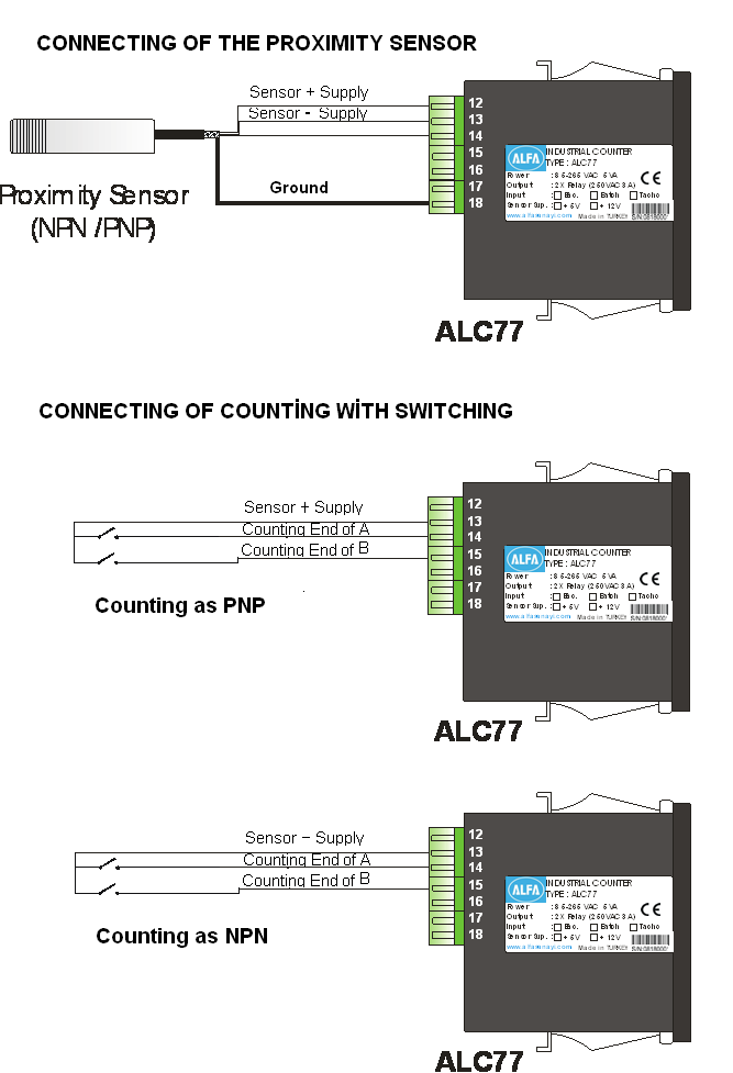
4 OUT 2 OUT CONNECTIONS Supply Voltage 24 VAC / DC or 85 / 265 VAC L N Vdc veya +12 Vdc GND Graund 3 14 A Input of Counting Signal COM NO NC B Input of Counting Signal Z Input of Reset Signal Input of Hold Signal Ground of Sensor COM 9 20 NO NC SAFETY WARNINGS 1. Follow the instructions and warnings in the user guide. 2. Please check the type of power supply, before connect energies the device. 3. Please the device mounted on panel against dangers of fall, snap, shake during working. 4. Make Sensor connections without energy on the device, do not connect in any way during operation. 5. Make sure that is shielded cables between device and sensor. 6. Do not leave the device exposed to a heat source (solar, heater etc.) 7. ALC77 industrial control device is not suitable for use in the external environment, Use only room conditions. 8. Wipe with a damp cloth to clean the device, do not use water, thinner etc. 9. Comply with the limit values specified in the technical specifications for relay outputs. 10. The device cannot be changed by the user in the event of a fault, Please contact our technical service in case of failure
5 - 3 -

6 3. DESCRIPTION OF FRONT PANEL ALC77 device operates in 2 different modes: Programming mode Operating modu : Specifies the function used during programming. : Specifies the function used during operating. Display and Position LEDs 1. 7 Digit LED Display (9,2mm) at operating mode: Indication of counting At programming mode: Indication of program parameter 2. 7 Digit LED Display (7mm) at operating mode: Indication of Set value. At programming mode: Indication of program parameter 3. Out-1 output LED position: On while the power at Out Out-2 output LED position: On while the power at Out Set-1 Led position: On while Set-1 value is displayed in the bottom display 6. Set-2 Led position: On while Set-2 value is displayed in the bottom display. Button Functions 7. RESET Button at operating mode: Used to reset of counted value. At programming mode: Using to exit without saving the entered value of the parameter and return to the operation mode. 8. PROG Button at operating mode: Used to return to the menu. At programming mode: Used to save and enter menu parameter value. 9. Down Button at operating mode: Used to in the bottom display to show the value of Set-1. At programming mode: Used to switch between the menus and decrease the value of the selected parameter. 10. Up Button at operating mode: Used to in the bottom display to show the value of Set-2. At programming mode: Used to switch between the menus and decrease the value of the selected parameter
7 4. DEVICE PROGRAMMING Enter to the menu and Changing Parameters: For Switch to programming mode while device operating mode push ( menu will appear on the screen. ) button. Firstly s Switch between program menus with Down ( ) and up ( ) buttons. button is entered into for the menu to be changed. Changes can save with prg ( ) button. Return to operating mode with Rst ( RST ) button. If password protection is activated at device, password must be entered. If password is correct, true message is displayed on the bottom line. Also password is incorrect, false is displayed. If Password is correct : true. If Password is incorrect: false 4.1. Entering The Set Point to Device (Set) Menu is displayed firstly on the screen as prg button is pressed while operating mode. Menu of Set 2 is displayed while down button is pressed. The top row shows the name of the menu and bottom row also (yellow marked) selected value in menu content. Set 1, set 2 allows controlling to out1 and out2 relays. Move to the desired set point for setting. The rightmost digit starts flashing when Prg button is pressed. Desired point is selected up and down button. Used to Prg button for digits scrolling. Shifted to the left for one step when each press of the button, If pres the prg button when coming the rightmost digits, positive or negative value will be asked. Value is selected by up and down button then saved with prg button. If you are not want to save, you can exit with esc button
8 4.2. Selection of Counter Type-Batch/Counter- (Dstype) This menu allows you to set the device type counter. There are two types of counter mode, Counter and Batch. At Batch or Counter mode, The counter counts forward or reverse according to signals of A and B channel depending on the type of the selected input. Besides counting is done as part, counting operation is performed according to the amount of part. The contents of the output menu will vary according to counter type selected. In order to determine counter type, entered to device menu with prg button at operation mode. Found to Dsptype menu with up-down button and pressed to prg button then bottom row choice flashes. Make the selection with up-down button and saved value by prg button. Then return with rst button to operating mode Selection of Input Type Forward/Backward (Cnt_Typ) The input type is selected and that determines the type of counting according to signals of A and B Channel depending on the type of the selected input. There are 8 different counting options. For detailed information refer to annex part at the end of the manual. In order to select counter type, pressed to prg button at operation mode. Found to Cnt_typ menu with up-down button and pressed to prg button then bottom row choice flashes. Make the selection with up-down button and saved value by prg button. Then return with rst button to operating mode. increases with A signal, reduced with B signal. increases with A signal, increases with B signal. Increases with A signal, A signal counts reverse, as long as becomes the B signal Reduced with A signal, A signal counts forward, as long as becomes the B signal. Reduced with A signal, Increases with B signal. Increases with A signal, A signal do not counti as long as becomes the B signal. Reduced with A signal, Reduced with B signal.. Reduced with A signal, A signal do not counti as long as becomes the B signal
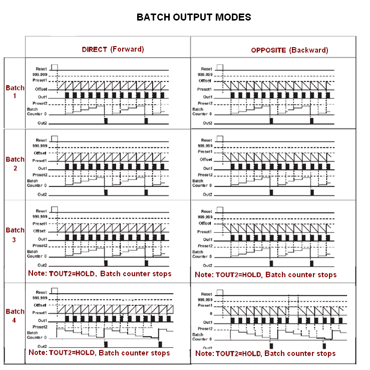
9 4.4. Relay Output Modes (Output) There are 11 different (7pieces counter, 4pieces batch) output type at output menu. If counter type is selected counter, selection menu 0 up to 7 is displayed on the bottom line of output menu. Choices are described below. For detailed information refer to annex part at the end of the manual. Press to prg button at operation mode. Found to output menu with up-down button and pressed to prg button then bottom row choice flashes. Make the selection with up-down button and saved value by prg button. Then return with rst button to operating mode. The relay function is turned off. When passed over Set1 value, Output1 will be active. When passed over Set2 value, Output2 will be active. When passed over Set1 value, Output1 will be active. When passed over Set2 value, Output2 will be active. Counter will be Hold position as long as without reset. When passed over Set1 value, Output1 will be active. When passed over Set2 value, Output2 will be active. Out1 will be inactive and the value on the screen returns to the ofset value. When passed over Set1 value, Output1 will be active. When passed over Set2 value, Output2 will be active. This mode is only forward / backward counting input type. When passed over Set1 value, Output1 will be active. When passed over Set2 value, Output2 will be active. So Output1 is not active. When passed over Set1 value, Output1 will be active. When passed over Set2 value, Output2 will be active. Out1 is not active. And then and the value on the screen returns to the ofset value. When passed over Set1 value, Output1 will be active. When passed over Set2 value, Output2 will be active. Out1 is not active. Counter will be Hold position as long as without reset. This mode is only forward / backward counting input type. If batch is selected as the counter type, the following choices appear in the output menu. Choices are described below. For detailed information refer to annex part at the end of the manual: When passed over Set1 value, Output1 will be active. the value on the screen returns to the ofset value and batch value increases. When Batch value reaches to set2 value, out2 will be active. Reached to offset value whileat Set1 value, Out1 will be active. The value on the secreen returns to Set1 value and Batch value increases. When Batch value reaches to set2 value, out2 will be active
10 When passed over Set1 value, Output1 will be active. The value on the secreen returns to Set1 value and Batch value increases. When Batch value reaches to set2 value, out2 will be active. IF hold is set as Out2 relay time, counter will switch hold position and do not count without resetting. Reached to offset value whileat Set1 value, Out1 will be active. The value on the secreen returns to Set1 value and Batch value increases. When Batch value reaches to set2 value, out2 will be active. IF hold is set as Out2 relay time, counter will switch hold position and do not count without resetting Relay Output Time (tout) Tout menus allow role output times according to entered times. If entered to time as zero, writes hold on the screen. Thus situated, relays will be active during the set value is exceeded. In order to entered output time, if you press to prg button, found tout1 or tout2 menus with up-down button. When press prg button, the right-digit of bottom row flashes. Its value is set with up-down button. Each press of the button moves to the left in a digit. Then you can save them. Therefore point is fixed Relay Output Positions (out) Out1 and out2 menus allow positions of the relays. The relay is inactive at Nclose option, active while reached set point. And also the relay is active at Nopen option, it will be inactive while reached set point Selection Of Input Frequency (in_freq) Used to input frequency filtering for prevent undesired interference. Frequencies of above from the selected value is not detected by the counter. In order to select input frequency, pressed to prg button at operating mode. Found in_freg menu with up-down button and pressed to prg button then bottom row choice flashes. Make the selection with up-down button and saved value by prg button. Then return with rst button to operating mode
11 4.8. Entering Offset Value (offset) Offset value can be entered using this menu to device. Return to entered offset value when pressed to rst button or signal comes from Z input. If offset value is zero and reset button is pressed, zero will write on the screen. Found offset menu with up-down button and pressed to prg button then bottom row choice flashes. Set to value with up-down button and each press of the button moves to the left in a digit. Then you can save them Demonstration of the Total Value of the Counter (total) This menu determines to display which values on the screen. In order to select value, pressed to prg button at operating mode. Found total menu with up-down button and pressed to prg button then bottom row choice flashes. Change to option with up-down button and save choice with prg button then return to operation mode with rst button. Counter Out1 Out2 Nototal : Shows the value of the counter. : Shows number of Relay-1 operating. : Shows number of Relay-2 operating. : The function doesn t work Selection Of The Reset Value Of The Counter (Cnt Rst) Cnt Rst menu determines the value of the counter will be zero or not zero. If it s on position, the value can be reset or if it s off position, counter does not reset. In order to select choice, pressed to prg button at operating mode. Found Cnt Rst menu with up-down button and pressed to prg button then bottom row choice flashes. Change to option with up-down button and save choice with prg button then return to operation mode with rst button.
12 4.11. Batch Reset (bat rst) Batch Rst menu determines to reset of batch value when pressed up-down button for two times at operating mode. If bat rst is on position, pressing the reset button for about 2 seconds, the value is reset. If it is off position, the value is not reset. In order to open batch reset, pressed to prg button at operating mode. Found Bat Rst menu with up-down button and pressed to prg button then bottom row choice flashes. Changed to option with up-down button and save choice with prg button then return to operation mode with rst button Reset of Total Value (tot rst) Tot rst determines to reset of total value when pressed up-down button for two times at operating mode. If Tot rst is on position, pressing the reset button for about 2 seconds, the value is reset. If it is off position, the value is not reset. In order to open batch reset, pressed to prg button at operating mode. Found Tot Rst menu with up-down button and pressed to prg button then bottom row choice flashes. Changed to option with up-down button and save choice with prg button then return to operation mode with rst button Reset With Button (rst btn) This menu allows becoming active RST button on the front panel. While RST button is active, the value of the onscreen will be reset when pressed up-down button for two times at operating mode or return to offset value. In order to open RST button, pressed to prg button at operating mode. Found Tot Rst menu with up-down button and pressed to prg button then one of reset/noreset choice at bottom row flashes. Change to option with up-down button and save choice with prg button then return to operation mode with rst button
13 4.14. Reset With External Z Signal (rst inpt) Resetting at device screen can be done with by applied from outside external an encoder Z signal or a switch when External Z input is be activated. While you make active the Z input, select the edge you will make reset on. You can select one of rising and falling edges. If you don t want to use Z input, select to noreset option. In order to activate to Z input, pressed to prg button at operating mode and found rst inpt menu with up-down button. When Prg button is pressed, options will flash and made the selection with updown button. Then save it by prg button Activating The Hold Input (Hold) While hold input is active, value on the screen is fixed when coming the signal of hold input. If signal of hold input isn't cut, counting can not to be continued. While you select the hold input, also select the edge you will make reset on. You can select one of Rising and falling edges. If you want to hold off Input, select to off option. In order to select to Hold Input, pressed to prg button at operating mode and found hold menu with up-down button. When prg button is pressed, options will flash and made the selection with updown button. Then save it by prg button Selection Sensor Type (Npn/Pnp) (Senstyp) The used sensor type can be select from this menu. The sensor output signal is selectable as NPN or PNP. In order to selected sensor type, pressed to prg button at operating mode and fount S.typ menu with updown button. When prg button is pressed, options will flash and made the selection with up-down button. Then save it by prg button and return with rst button to operating mode
14 4.17. Return To Factory Defaults (Factory) Factory menu enables to return the first fabrication settings of device. At this situated, all device setting will change and for this reason important settings should be saved previously. Device will require the password for returning to factory defaults and this password is 454. In order to return to factory defaults, pressed to prg button at operating mode and found to factory menu with up-down button. When prg button is pressed at menu screen, The right-digit of bottom row is flashing and changed value with updown button. When pressing to prg button, moves to the left in a digit and you can set it as 454 and press to prg button. So device will return to factory defaults Keeping In Memory When The Power Fails (Data) Data menu enables to keep in memory the last value on the screen even if the energy is cut off and must be selected record for this option. So the final value will be memorized when energy is cut off and resumes again when energy comes back. Recording process will not be stored to device memory while clear is selected, and then value will start from zero. In order to change data menu, pressed to prg button at operating mode and found data menu with up-down button. Then save it by prg button and return with rst button to operating mode
15 4.19. Password Protection (Code_in) Password security enables that unauthorized persons is prevented to change the parameters of the menu. If Code-in menu is on position, you can enter to device s menu and password is required for any setting changes. If the password is wrong, you cannot change anything. While Code_in menu is off, the password protection is not active. If Code_in menu is on, recode is added to menu titles. In order to turn on Code-in menu, pressed to prg button at operating mode and found Secu Menu with up-down button. Then save it by prg button. When Code_in menu is on position, recode is added to menu titles. Recode menu enables identification of password to device. Default password is 000, if you have not changed. When prg button is pressed at menu screen, the right-digit of bottom row is flashing and changed value with up-down button. When Pressed to prg button, moves to the left in a digit. So you can set the value with up-down button and save them when pressed to prg button at third digit. So password is defined
16 4.20. Annex A Graphics of Input Signal Types (Output Menu)
 - 15")
17 4.21. Annex B Graphics of RELAY OUTPUT Types (Output Menu)
18 - 16 -
19 5. CERTIFICATE OF WARRANTY Product : ALC77 B 85/265 VAC 24 VAC/DC TTL Push Pull Serial No : This product is guaranteed for two years against manufacturing defects. Conditions out of the warranty: - Mechanical damage - Shipping damage - Users error Other situations are covered by the manufacturer's warranty. Signature and Stamp
 399 44 04 Fax : +90 (216) 399 44 02 Web:")
20 ATEK SENSOR TECHNOLOGY A.S. Cevizli Mah. Bagdat Cad. Guven Sok. No:11 TR Maltepe / Istanbul - TURKEY Tel: +90 (216) Fax : +90 (216) Web: info@ateksensor.com
FLOW CALCULATOR INSTRUCTION MANUAL MESURES BAMOPHOX 759 26-06-2007 759 M1 02 E MES FLOW CALCULATOR 759-02/1
 BAMOPHOX 759 E - M FLOW CALCULATOR INSTRUCTION MANUAL MESURES 22, Rue de la Voie des Bans - Z.I. de la Gare - 95100 ARGENTEUIL Tél : (33) 01 30 25 83 20 - Web : www.bamo.fr Fax : (33) 01 34 10 16 05 -
Preset Counter signo 721
 Most simple handling Impressive, clearly readable display in 48x48 mm Input frequency up to 60 khz Easy installation due to pluggable terminals TECHNICAL DATA GENERAL Display Height of digits Supply voltage
SENSORS. Fiber Optic Sensors - S70. Advanced fiber optic amplifiers for high speed and low contrast applications
 Fiber Optic Sensors - S7 Advanced fiber optic amplifiers for high speed and low contrast applications DIN rail mountable models with dual digital displays speed models: 2 μs...5 ms Super high speed models:
Points Position Indicator (PPI1) for Points Motors with Common Ground
 for Points Motors with Common Ground") Points Position Indicator (PPI1) for Points Motors with Common Ground Monitors Points Action and Operates Leds on a Control Panel Monitors the brief positive operating voltage across points motors when
Points Position Indicator (PPI1) for Points Motors with Common Ground Monitors Points Action and Operates Leds on a Control Panel Monitors the brief positive operating voltage across points motors when
Data sheet GIOD.1 Input/output module with CAN bus. ERP no.: 5204183. www.guentner.de. Data sheet GIOD.1 V_3.0
 Data sheet GIOD.1 Input/output module with CAN bus ERP no.: 5204183 www.guentner.de Page 2 / 10 Contents 1 GIOD.1... 3 1.1 Functional description...3 1.2 Connections... 5 1.3 Electrical properties of...
WEA-Base. User manual for load cell transmitters. UK WEA-Base User manual for load cell transmitters Version 3.2 UK
 WEA-Base User manual for load cell transmitters 1 Contents 1. Technical data... 3 2. Assembly... 4 2.1 Power supply... 4 2.2 Load cells... 4 2.3 RS-485... 4 2.4 Relays... 5 2.5 Digital input... 5 2.6 Analogue
AC-115 Compact Networked Single Door Controller. Installation and User Manual
 AC-115 Compact Networked Single Controller Installation and User Manual December 2007 Table of Contents Table of Contents 1. Introduction...5 1.1 Key Features... 6 1.2 Technical Specifications... 7 2.
Technical data. General specifications. Signal voltage 15... 30 V DC Signal duration. 1 s Input 2. Signal voltage. 1 s Analog output.
 Model Number Features Very small housing High climatic resistance 4 Bit multiturn Analog output Surge and reverse polarity protection Description This absolute rotary encoder with internal magnetic sampling
POINTS POSITION INDICATOR PPI4
 POINTS POSITION INDICATOR PPI4 Advanced PPI with Adjustable Brightness & Simplified Wiring Monitors the brief positive operating voltage across points motors when they are switched Lights a corresponding
ERMA-Electronic GmbH - Max-Eyth-Str.8-78194 Immendingen - Tel: +49(0)7462/2000-0 - Fax: +49(0)7462/2000-29. Technische Änderungen vorbehalten
7462/2000-0 - Fax: +49(0)7462/2000-29. Technische Änderungen vorbehalten") Panel mounting instruments / DIN cabinets mounting different standard housing sizes different supply voltages all usual measured variables Measuring instruments programmable industrialfair execution customized
Panel mounting instruments / DIN cabinets mounting different standard housing sizes different supply voltages all usual measured variables Measuring instruments programmable industrialfair execution customized
Multifunction devices
 devices devices devices, electronic Type Page LED multifunction displays pulse, frequency, time (DC) Codix 524 240 pulse, frequency, time (AC+DC) Codix 544 243 LCD multifunction preset counters 1 or 2
Inductive Sensors Single or Dual Loop Detectors Type LD with teach-in
 Inductive Sensors Single or Dual Loop Detectors Type LD with teach-in Single or Dual loop detector Automatically adjustment of detection level Manual sensitivity for compensations of variations Easy installation
Flexible Counter Series in DIN size 24 x 48 mm
 Flexible Counter Series in DIN size 24 x 48 mm high contrast 8-digit LCD display or brilliant 6-digit LED display 2 different supply voltages available: independent of mains supply with lithium battery
User s Manual Before using the inverter, you need to read and save the safety instructions.
 User s Manual Before using the inverter, you need to read and save the safety instructions. STI SERIES (STI200, STI300, STI500, STI700, STI1000) Power Frequency Pure Sine Wave Inverter The information
Point of view HDMI Smart TV dongle Mini RF Keyboard
 Point of view HDMI Smart TV dongle Mini RF Keyboard English Contents Contents... 1 General notices for use... 2 Disclaimer... 2 Box Contents... 2 1. HDMI TV dongle... 3 1.1. Product display... 3 1.2. Instructions
T0118 T2118 T3118. Instruction Manual
 Programmable indoor transmitter of temperature T0118 Programmable indoor transmitter of atmospheric pressure T2118 Programmable indoor transmitter of temperature, relative humidity and other derived humidity
Introduction. Refrigerant Leak Detecting System. Feature and Benefits
 PSC European Refrigeration Controls Catalogue Catalog Section 9 Product Bulletin PD-GAS-E Refrigerant Leak Detecting System Introduction This range of refrigerant leak detecting systems is designed for
RI-215A Operator s Manual. Part Number: 71-0045RK Revision 0 Released: 10/3/05
 RI-215A Operator s Manual Part Number: 71-0045RK Revision 0 Released: 10/3/05 Warranty RKI Instruments, Inc., warrants gas alarm equipment sold by us to be free from defects in materials and workmanship,
700/732 SERIES. 5mm HOUR METERS & COUNTERS. CURTIS INSTRUMENTS, INC. 200 Kisco Avenue, Mt. Kisco, NY 10549 Tel. (914) 666-2971 FAX (914) 666-2188
 666-2971 FAX (914) 666-2188") 700/732 SERIES CURTIS INSTRUMENTS, INC. 200 Kisco Avenue, Mt. Kisco, NY 10549 Tel. (914) 666-2971 FAX (914) 666-2188 www.curtisinst.com 53004 REV F 06/02 5mm HOUR METERS & COUNTERS Read Instructions Carefully
700/732 SERIES CURTIS INSTRUMENTS, INC. 200 Kisco Avenue, Mt. Kisco, NY 10549 Tel. (914) 666-2971 FAX (914) 666-2188 www.curtisinst.com 53004 REV F 06/02 5mm HOUR METERS & COUNTERS Read Instructions Carefully
Inductive Proximity Sensors
 M12 Inductive Proximity Sensors Standard Length Mini's Extended Sensing 3 Wire DC 2 Wire DC 2 Wire AC (Wiring Schematic) 3 Wire DC PNP Normally Open (1) IMM32122C IMM35124C IMN32122C IMN35124C IMN32122M12
MANUAL PC1000R INFO@APART-AUDIO.COM
 MANUAL PC1000R INFO@APART-AUDIO.COM Features The APart PC1000R is a professional multisource CD/USB/SD card music player, equipped with balanced and unbalanced analog outputs, coaxial and optical digital
Tubular Analog model resolution: 0,5 mm (SLOW mode), 1 mm (FAST mode) Right angle Repeatibility: 0,7 mm Vdc
, 1 mm (FAST mode) Right angle Repeatibility: 0,7 mm Vdc") Ultrasonic sensors for high precision detection of clear and transparent objects Clear object detection, inspection on transparent or highly reflective film and liquid level measurement Standard M18 tubular
Ultrasonic sensors for high precision detection of clear and transparent objects Clear object detection, inspection on transparent or highly reflective film and liquid level measurement Standard M18 tubular
CAD-05 Kit GSM Auto Dialer. Owner s Manual
 CAD-05 Kit GSM Auto Dialer Owner s Manual CAD-05 Kit Manual.indd 1 Warnings: This device complies with Part 15 of the FCC rules, Operation of this device is subject to the following conditions: 1. This
EBDSPIR-PRM, EBDSPIR-PRM-IP
 Product Guide EBDSPIR-PRM, EBDSPIR-PRM-IP Ceiling PIR presence/absence detector Overview The EBDSPIR-PRM PIR (passive infrared) presence detector provides automatic control of lighting loads with optional
Single Channel Loop Detector
 Single Channel Loop Detector Model - LD100 Series The LD100 is a single channel inductive loop detector designed for parking and access control applications. The detector is connected to an inductive loop
DLP-PU/E Instruction Manual
 Instruction Manual BEFORE USING THE POWER SUPPLY UNIT Pay attention to all warnings and cautions before using the unit. Incorrect usage could lead to an electrical shock, damage to the unit or a fire hazard.
Autodialler. Installation & Programming Guide HYL004. Please read these instructions before you start the installation. Installation.
 Autodialler HYL004 Installation & Programming Guide Features Please read these instructions before you start the installation LCD Display Programmable 9 x 32 digit phone numbers for each trigger. 10 second
www.sebury.com.cn Digital Keypad Use s Manual
 K3 K4 www.sebury.com.cn Digital Keypad Use s Manual Contents Introduction Introduction Specifications Intramural Interface Circuit 3 Mounting 3 Wiring 5 Power UP 7 Engineer Programming Mode 7 The K3/K4
Analogue Input, 4-fold, MDRC AE/S 4.1, GH Q605 0054 R0001
 Analogue Input, -fold, MDRC, GH Q605 005 R0001 The analogue input is a DIN rail mounted device for insertion in the distribution board. It is connected to the EIB via the bus connecting terminal supplied.
Drayton Digistat +2RF/+3RF
 /+3RF Programmable Room Thermostat Wireless Model: RF700/22090 Model: RF701/22092 Power Supply: Battery - Thermostat Mains - Digistat SCR Invensys Controls Europe Customer Service Tel: 0845 130 5522 Customer
LS1024B / LS2024B/ LS3024B. Solar Charge Controller USER MANUAL
 EPSOLAR LS1024B / LS2024B/ LS3024B Solar Charge Controller USER MANUAL Thank you very much for selecting our product! This manual offers important information and suggestions with respect to installation,
Power source. Input. Contact / Open collector Voltage input (SELECTABLE) AC100-240V DC12-24V AC100-240V. Output indicator
 AC100-240V DC12-24V AC100-240V. Output indicator") SERIES Electronic Preset Counter Instruction Manual Please note that misuse of this device may lead to injury to the user or damage to the device. Please observe all safety precautions and warnings in
SERIES Electronic Preset Counter Instruction Manual Please note that misuse of this device may lead to injury to the user or damage to the device. Please observe all safety precautions and warnings in
PRODUCTIVITY THROUGH INNOVATION 600 CONTROL DIRECT DRIVE TECHNICAL/OPERATION MANUAL
 Rev. D PRODUCTIVITY THROUGH INNOVATION 600 CONTROL DIRECT DRIVE TECHNICAL/OPERATION MANUAL 10 BORIGHT AVENUE, KENILWORTH NEW JERSEY 07033 TELEPHONE: 800-524-0273 FAX: 908-686-9317 TABLE OF CONTENTS Page
IRT Eurocard. Type DAX-3206. Audio Extractor for 270 Mb/s SDI
 I R T Electronics Pty Ltd A.B.N. 35 000 832 575 26 Hotham Parade, ARTARMON N.S.W. 2064 AUSTRALIA National: Phone: (02) 9439 3744 Fax: (02) 9439 7439 International: 61 2 9439 3744 61 2 9439 7439 Email:
PD 100A. Printing data system
 PD 100A Printing data system Operating instructions ENGLISH IMPORTANT: Read these instructions carefully before installing and using the device; do not forget following all additional information. Keep
Short information Parameters are programmed via front-side membrane keypad
 Digital remote display for Flow Meter DM /DE Universal meter UZ Indication of the quantity consumed in m³ Features LED-Display 14.2mm red Indicating range -99999... 999999 0... 3 Decimal points programmable
INSTALLATION/PROGRAMMING INSTRUCTIONS E4KP ENTRYCHECK
 Security Door Controls 3580 Willow Lane, Westlake Village, CA 91361-4921 (805) 494-0622 Fax: (805) 494-8861 www.sdcsecurity.com E-mail: service@sdcsecurity.com INSTALLATION/PROGRAMMING INSTRUCTIONS E4KP
Variable Preset Counter signo 723.1
 Variable Preset Counter signo 723.1 Large, 6-digit, 14 mm high LED display Up/down counter with prescaler 2 presets, one programmable as trailing preset Easy direct selection by 2 function keys 2 relay
T7560A,B,C Digital Wall Module
 T7560A,B,C Digital Wall Module HONEYWELL EXCEL 5000 OPEN SYSTEM BEFORE INSTALLATION All wiring must comply with local electrical codes and ordinances or as specified on installation wiring diagrams. Digital
Programmable Room Thermostat 7 Day (5-2 Day) Models: 22083 / 22087 Power Supply: Battery / Mains
 Models: 22083 / 22087 Power Supply: Battery / Mains") Drayton Programmable Room Thermostat 7 Day (5-2 Day) Models: 22083 / 22087 Power Supply: Battery / Mains Invensys Controls Europe Technical Helpline: +44 (0) 845 130 7722 www.draytoncontrols.co.uk Installation
Drayton Programmable Room Thermostat 7 Day (5-2 Day) Models: 22083 / 22087 Power Supply: Battery / Mains Invensys Controls Europe Technical Helpline: +44 (0) 845 130 7722 www.draytoncontrols.co.uk Installation
Back-UPS Pro 1300/1500 Installation and Operation
 Back-UPS Pro 1300/1500 Installation and Operation Inventory Safety Do not install the Back-UPS in direct sunlight, in excessive heat, humidity, or in contact with fluids. Connect the battery bu059a bu058a
FL ballasts Electronic dimming. PCA T5 BASIC lp Y II, 14 80 W BASIC T5
 T5 TC-L PCA T5 BASIC lp Y II, 1 80 W BASIC T5 Product description Processor-controlled ballast with y II inside Highest possible energy class CELMA EEI = A1 BAT 1 Noise-free precise control via DSI signal,
Contactless Encoder RI360P0-QR24M0-INCRX2-H1181
 Compact, rugged housing Many mounting possibilities Status displayed via LED Immune to electromagnetic interference 1024 pulses per revolution (default) 360, 512, 1000, 1024, 2048, 2500, 3600, 4096, parametr.
How To Program An Autodialer
 GJD HYL005 GSM Autodialer Instruction Manual Please read these instructions before you start the installation Features: LCD display. Programmable 9 x 32 digit phone numbers for each trigger. 10 second
FACTORY AUTOMATION. Manual. Speed Monitor KHU8-DW-1.D
 FACTORY AUTOMATION Manual Speed Monitor KHU8-DW-.D With regard to the supply of products, the current issue of the following document is applicable: The General Terms of Delivery for Products and Services
Contents. Document information
 User Manual Contents Document information... 2 Introduction... 3 Warnings... 3 Manufacturer... 3 Description... Installation... Configuration... Troubleshooting...11 Technical data...12 Device Scope: PCB
Firmware version: 1.10 Issue: 7 AUTODIALER GD30.2. Instruction Manual
 Firmware version: 1.10 Issue: 7 AUTODIALER GD30.2 Instruction Manual Firmware version: 2.0.1 Issue: 0.6 Version of the GPRS transmitters configurator: 1.3.6.3 Date of issue: 07.03.2012 TABLE OF CONTENTS
LED red (-): Measuring value < lower tolerance threshold LED red (+): Measuring value > upper tolerance threshold. Page 1/6
: Measuring value < lower tolerance threshold LED red (+): Measuring value > upper tolerance threshold. Page 1/6") L-LAS Series L-LAS-LT-165-CL - Line laser 1 mw, laser class 2 - Visible laser line (red light 670 nm), typ. 2 mm x 3 mm - Reference distance approx. 165 mm - Measuring range typ. 65... 265 mm - Resolution
L-LAS Series L-LAS-LT-165-CL - Line laser 1 mw, laser class 2 - Visible laser line (red light 670 nm), typ. 2 mm x 3 mm - Reference distance approx. 165 mm - Measuring range typ. 65... 265 mm - Resolution
FAQ s on Siemens Magmeters
 FAQ s on Siemens Magmeters 1. The cables for the coils and electrodes for the magmeters look the same. Does it matter which cable is used for coils and which one is used for the electrodes? Both cables
Operating Manual for the Electronic Built-in Interval Timer. Micro II (Countdown Timer)
") Operating Manual for the Electronic Built-in Interval Timer Micro II (Countdown Timer) Note: This document has been designed for our OEM customers. They can use it as supporting material when creating
Operating Manual for the Electronic Built-in Interval Timer Micro II (Countdown Timer) Note: This document has been designed for our OEM customers. They can use it as supporting material when creating
Transmitter Interface Program
 Transmitter Interface Program Operational Manual Version 3.0.4 1 Overview The transmitter interface software allows you to adjust configuration settings of your Max solid state transmitters. The following
ZC-24DO CANopen I/O Module: 24 Digital Outputs
 Z-PC Line EN ZC-24DO CANopen I/O Module: 24 Digital Outputs Installation Manual Contents: - General Specifications - Technical Specifications - Installation Rules - Electrical connections - DIP-switches
Doc.No. NDP 192U-02. Electric Pump Controller CE-124P. Instruction Manual
 Doc.No. NDP 192U-02 Electric Pump Controller CE-124P Instruction Manual 1. Parts Name and Function 1) POWER LED Indicate that CE-124P is powered up. 2) START/STOP KEY (SELECTOR KEY) Used to start and stop
Series 427. 1/16 DIN Multi-Mode Bar Graph Display Timer TIMERS PRODUCT HIGHLIGHTS
 Series 427 1/16 DIN Multi-Mode Bar Graph Display Timer PRODUCT HIGHLIGHTS Digital Setting with 0.1% Accuracy Unique LED Bargraph Indicates Time Cycle in 20% Increments 8 Field Selectable Modes of Operation
Solar Controller / Battery Charger User s Manual
 Solar Controller / Battery Charger User s Manual 1 Congratulations! You have made an excellent choice by purchasing this high quality KORR PWM solar controller which has been manufactured to the highest
[F/T] [5] [KHz] [AMP] [3] [V] 4 ) To set DC offset to -2.5V press the following keys [OFS] [+/-] [2] [.] [5] [V]
![[F/T] [5] [KHz] [AMP] [3] [V] 4 ) To set DC offset to -2.5V press the following keys [OFS] [+/-] [2] [.] [5] [V]](/thumbs/40/20623504.jpg "[F/T] [5] [KHz] [AMP] [3] [V] 4 ) To set DC offset to -2.5V press the following keys [OFS] [+/-] [2] [.] [5] [V]") FG085 minidds Function Generator Manual of Operation Applicable Models: 08501, 08501K, 08502K, 08503, 08503K Applicable Firmware Version: 1 ) 113-08501-100 or later (for U5) 2 ) 113-08502-030 or later
FG085 minidds Function Generator Manual of Operation Applicable Models: 08501, 08501K, 08502K, 08503, 08503K Applicable Firmware Version: 1 ) 113-08501-100 or later (for U5) 2 ) 113-08502-030 or later
Duct Humidity Transmitter
 SDC-H Duct Humidity Transmitter Features Replaceable sensor element Humidity measurement for air ducts Minimum and maximum value memory 0 0V, 0 0mA or 0V, 4 0mA measuring signals selectable with jumpers
Multi-Protocol decoder 76 200 with Load regulation
 Multi-Protocol decoder 76 2 with Load regulation For locomotives with universal motors on digital layouts operating in the DCC and Motorola data format. Features 76 2 Load regulated multi-protocol decoder
Operation Manual. Plasma torch height controller. Model: Compact THC Controller 150
 Operation Manual Plasma torch height controller. Model: Compact THC Controller 150 Notes on safety WHEN THE DEVICE IS IN OPERATION, VOLTAGE HAZARDOUS TO HEALTH AND HUMAN LIFE IS PRESENT INSIDE THE HOUSING
AM / FM Tuner + RDS. Model: TU-101. www.pulse-audio.co.uk
 AM / FM Tuner + RDS Model: TU-101 www.pulse-audio.co.uk 1 Safety Information The lightning bolt within a triangle is intended to alert the user to the presence of dangerous voltage levels within the product
CruzPro VAF110. AC Volts, Amps, Frequency, kw Monitor
 CruzPro VAF110 AC Volts, Amps, Frequency, kw Monitor Table of Contents Introduction............................ 3 Specifications........................... 4 Installation..............................5
INTELLIGENT CONTROL MODULE SA-2000-II HARDWARE MANUAL. Access Technologies International, Inc.
 SA-2000-II HARDWARE MANUAL Access Technologies International, Inc. 1 Table of Contents 1. Introduction 3 2. Features 3 3. Specification 4 4. Identifying Supplied Parts 4 5. Panel Description 5 6. Connection
Electronic Control Devices The European Product Catalogue 2007
 FX07 Field Controller (1/4) FX07 Field Controller Display Model Dimensions in mm (inches) The FX07 is a terminal unit controller in the Facility Explorer range of products. The controller is designed specifically
KCIEN KCIENSBP. Heavy Duty Stainless Steel Illuminated Keypads INSTALLATION MANUAL. Range: DIGICODE (Stand-Alone Keypad)
") KCIENSBP KCIEN Heavy Duty Stainless Steel Illuminated Keypads Range: DIGICODE (Stand-Alone Keypad) INSTALLATION MANUAL Features: Input voltage: 12V to 24V AC or 12V to 48V DC Illuminated keys Heavy duty
KCIENSBP KCIEN Heavy Duty Stainless Steel Illuminated Keypads Range: DIGICODE (Stand-Alone Keypad) INSTALLATION MANUAL Features: Input voltage: 12V to 24V AC or 12V to 48V DC Illuminated keys Heavy duty
GSM Autodialer Professional GJD700 Speech & Text Autodialer
 Text Edit message GSM Autodialer Professional GJD700 Speech & Text Autodialer Introduction The GSM Autodialer Professional works in conjunction with standard alarm systems and makes use of your preferred
DAB+ / FM Tuner Model: TU-201
 DAB+ / FM Tuner Model: TU-201 Instruction Manual www.pulse-audio.co.uk 1 Safety Information The lightning bolt within a triangle is intended to alert the user to the presence of dangerous voltage levels
focus TOuCh P10 FOR DISPLAYS: 55, 70 AND 82 ENgliSh V01.3-2014-7
 focus TOuCh P10 FOR DISPLAYS: 55, 70 AND 82 ENgliSh V01.3-2014-7 Thank you for purchasing our product. Please read this manual carefully before operation your set and retain it for future reference. FT55-P10
AUTODIALLER / QUICKDIALLER - SA132
 AUTODIALLER / QUICKDIALLER - SA132 INSTRUCTION LEAFLET ENGLISH www.thermomax-group.com CONTENTS 1 SETUP AT A GLANCE... 2 2 FOREWORD....... 3 3 INSTALLATION...... 4 4 KEYPAD AND INDICATORS...... 5 SETTING
Temperature & Humidity SMS Alert Controller
 Temperature & Humidity Alert Controller METERS 3 simple steps starting the unit: Insert the SIM card Plug in the sensors connectors Connect the AC power cord. Specifications: AC 90~260V Auto Select Internal
Operating instructions Diffuse reflection sensor. OJ50xx 701396 / 01 07 / 2004
 Operating instructions Diffuse reflection sensor OJ50xx 7096 / 0 07 / 004 Contents Preliminary note. Symbols used Function and features Installation. Installation of the supplied mounting fixture 4 4 Electrical
Electronic Control Devices The European Product Catalogue 2007
 FX14 Field Controller (1/4) FX14 Field Controller The FX14 is an equipment field controller in the Facility Explorer range of products. The controller is designed specifically for commercial Heating, Ventilating,
INSTALLATION INSTRUCTIONS
 LIGHTING CONTROL PANELS 4 AND 8 RELAYS INSTALLATION INSTRUCTIONS INSTALLATION OVERVIEW The installation instructions contained in this document are provided as a guide for proper and reliable installation.
OPERATING INSTRUCTIONS
 PIPELINE INSPECTION COMPANY LTD. OPERATING INSTRUCTIONS Wet Sponge Holiday Detectors 670,673, and MSRB Wet Sponge Holiday Detectors Portable and In-Plant Detectors Table of Contents General Information.......................3
CelluLine CGW-TS GSM Cellular Gateway. Installation and Programming Manual
 CelluLine CGW-TS GSM Cellular Gateway Installation and Programming Manual CelluLine CGW-TS GSM Cellular Gateway Installation and Programming Manual CGWTS-M001A Version 1, Release 1, December 2004 NOTICE
Digital I/O: OUTPUT: Basic, Count, Count+, Smart+
 Digital I/O: OUTPUT: Basic, Count, Count+, Smart+ The digital I/O option port in the 4-Series provides us with 4 optically isolated inputs and 4 optically isolated outputs. All power is supplied externally.
Technical Manual. FAN COIL CONTROLLER COOLING or HEATING ANALOG or PWM Art. 119914 631001A
 COOLING or HEATING ANALOG or PWM Art. 119914 631001A TOTAL AUTOMATION GENERAL TRADING CO. LLC SUITE NO.506, LE SOLARIUM OFFICE TOWER, SILICON OASIS, DUBAI. UAE. Tel. +971 4 392 6860, Fax. +971 4 392 6850
NÜVE SANAYİ MALZEMELERİ İMALAT VE TİCARET A.Ş. OT 020 BENCH TOP STEAM STERILIZER USER S MANUAL
 NÜVE SANAYİ MALZEMELERİ İMALAT VE TİCARET A.Ş. OT 020 BENCH TOP STEAM STERILIZER USER S MANUAL NÜVE SANAYİ MALZEMELERİ İMALAT VE TİCARET A.Ş. Esenboğa Yolu 22 km Akyurt - ANKARA / TURKEY Tel : (00 90 312)
User Manual. ATX12V / EPS12V Power Supply TG-I460R (460W+460W) TG-I550R (550W+550W) Switching Power Supply User Manual
 TG-I550R (550W+550W) Switching Power Supply User Manual") ATX12V / EPS12V Power Supply TG-I460R (460W+460W) TG-I550R (550W+550W) User Manual Table of Contents 1 Introduction 2 General specification 3 Installation 4 Pin assignment & function of connectors 5 Drawing
ATX12V / EPS12V Power Supply TG-I460R (460W+460W) TG-I550R (550W+550W) User Manual Table of Contents 1 Introduction 2 General specification 3 Installation 4 Pin assignment & function of connectors 5 Drawing
IPX AUTOMATIC IP NETWORK LOSS BACKUP A/B SWITCH INSTRUCTION BOOK IB6444-02
 IPX AUTOMATIC IP NETWORK LOSS BACKUP A/B SWITCH INSTRUCTION BOOK IB6444-02 TABLE OF CONTENTS DESCRIPTION 2 MOUNTING INSTRUCTIONS 2 HOW TO CABLE THE IPX 2/3 POWER SUPPLY INSTALLATION 3 OPERATION 3 CARE
SENSORS. Miniature Sensors - S3Z. Advanced line of miniature Asian style of photoelectric sensors. 40-300 mm background suppression
 Advanced line of miniature Asian style of photoelectric sensors 4-3 background suppression.7 m proximity, 15 with narrow beam 4 m polarized retroreflective 3 m LASER through beam Standard 3-wire output
AutoRanging Digital MultiMeter
 Owner's Manual AutoRanging Digital MultiMeter Model No. 82139 CAUTION: Read, understand and follow Safety Rules and Operating Instructions in this manual before using this product. Safety Operation Maintenance
NC-12 Modbus Application
 NC-12 Modbus Application NC-12 1 Table of Contents 1 Table of Contents... 2 2 Glossary... 3 SCADA...3 3 NC-12 Modbus in general... 3 4 Entire system... 4 4.1 PFC to PC connection alternatives...4 4.1.1
WD-AMX Water Detection Controllers
 Page 1 of 5 WD-AMX Water Detection Controllers Features: Benefit: LED Status of leak status VFC output Audible alarm Auto or manual reset alarm output Uses an isolated AC signal which prevents oxidation
Application/Connection Examples
 This Quick Start Guide is designed to familiarize the user with the connection and configuration of the DTS-305 DIN rail mounted single / 3 phase power & energy meter with RS-485 or TCP communications.
Technote. Frese OPTIMA Compact actuators DN10-DN32. Application. Features thermic actuators. Features motoric actuators. Approval. www.frese.
 Page 1 of 6 Application Proportional 0-10V or 3-position modulating or On/ Off control of Frese OPTIMA Compact valves in heating, ventilating and air conditioning systems. The actuator can be mounted on
PLC Control Unit for a CSM-C Steam Compact Clean Steam Generator
 3.635.5275.251 IM-P486-19 CH Issue 2 PLC Control Unit for a CSM-C Steam Compact Clean Steam Generator Installation, Start-up and Operation Manual 1. Safety information 2. General product information 3.
GSM AD05 Slave GSM Auto Dialer- Instruction Manual
 GSM AD05 Slave GSM Auto Dialer- Instruction Manual Please read these instructions before you start the installation Features LCD display Programmable 9 x 32 digit phone numbers for each trigger. 10 second
Vibration Monitoring System Adash 3600
 " User's guide Application: Vibration Monitoring System Adash 3600! Vibration diagnostics, monitoring and protective on-line system! On-line vibration monitoring system of engines, fans, pumps, gearboxes,
RAINCONTROL LCD Special
 RAINCONTROL LCD Special edition 1.1 01/2007 - code 5880 1/16 RAINCONTROL LCD SPECIAL... 3 RAINCONTROL SPECIAL LCD PANEL PRESENTATION... 4 AUTO... 5 LOW AND HIGH THRESHOLD SETTING... 6 LOW THRESHOLD...
ALARM ANNUNCIATOR ME - 3010 INSTRUCTION MANUAL
 ALARM ANNUNCIATOR ME - 3010 INSTRUCTION MANUAL INTRODUCTION... 2.. TECHNICAL DATA... 3 ACCESSORIES... 5. INSTALLATION... 7 OPERATION... 12. TECHNICAL INFORMATION... 13 MAINTENANCE... 14. CONFIGURATIONS...
CONFIGURABLE SAFETY RELAYS
 MSI-s/R, MSI-sx/Rx Configurable MSI provide important functions for the efficient flow of automated production processes Special features Combined guarding types by connecting up to 4 AOPDs Additional
CONFIGURABLE SAFETY RELAYS
 MSI-m/R, MSI-mx/Rx Configurable MSI Safety Relay with function for efficient material flow in a packaging application Special features Sequential or Parallel with automatic mode detection MSI-mx for separate
BlueSolar Pro Remote Panel For BlueSolar PWM-Pro charge controllers 12/24V 5, 10, 20, 30A Article number SCC900300000
 Manual EN BlueSolar Pro Remote Panel For BlueSolar PWM-Pro charge controllers 12/24V 5, 10, 20, 30A Article number SCC900300000 Contents EN 1.Important safety instructions... 2 2. Installation... 2 3.Product
PK-01. Standalone door control module. SATEL sp. z o.o. ul. Schuberta 79 80-172 Gdańsk POLAND tel. + 48 58 320 94 00
 Standalone door control module PK-01 Firmware version 1.00 pk-01_en 06/12 SATEL sp. z o.o. ul. Schuberta 79 80-172 Gdańsk POLAND tel. + 48 58 320 94 00 info@satel.pl www.satel.eu WARNINGS Read carefully
User's Guide. Integrating Sound Level Datalogger. Model 407780. Introduction
 User's Guide 99 Washington Street Melrose, MA 02176 Phone 781-665-1400 Toll Free 1-800-517-8431 Visit us at www.testequipmentdepot.com Back to the Extech 407780 Product Page Integrating Sound Level Datalogger
COLOR VIDEO DOOR PHONE CDV-71BE/D
 COLOR VIDEO DOOR PHONE CDV-71BE/D 513-11, Sangdaewon-dong, Jungwon-gu, Seongnam-si, Gyeonggi-do, Korea Int l Business Dept. : Tel.; +82-31-7393-540~550 Fax.; +82-31-745-2133 Web site : www.commax.com Printed
User Manual. Humidity-Temperature Chart Recorder. Model RH520
 User Manual Humidity-Temperature Chart Recorder Model RH520 Introduction Congratulations on your purchase of the Extech RH520 Temperature + Humidity Chart Recorder. The RH520 measures and displays Temperature,
Owner s Manual AWM910 JENSEN AWM910 COMPACT DISC PLAYER RADIO CD COMPACT MUSIC SYSTEM MUTE AUX BAND AUX IN PUSH PUSH PWR VOL ALARM T/F AUD SPK A SPK B
 AWM910 Owner s Manual COMPACT DISC PLAYER PUSH 1 2 3 4 5 6 RPT SCAN RDM H M PUSH PWR VOL ALARM SET ON/OFF EQ T/F AUD RADIO CD COMPACT MUSIC SYSTEM MUTE AUX BAND CD AUX IN A B A+B JENSEN AWM910 Thank You!
Business Audio System: Music & Messaging MP3 Player. by Grace Digital Audio. User Guide. Model No. GDI-USBM10
 Business Audio System: Music & Messaging MP3 Player by Grace Digital Audio User Guide Model No. GDI-USBM10 User Guide Contents Introduction 2 Safety & General Use Information 2 Features 3 Set Up & Operation
Model SRMD Setra Remote Monitoring Display
 Model SRMD Setra Remote Monitoring Display 1.0 GENERAL INFORMATION Thank you for purchasing the Setra Remote Monitoring Display (SRMD). The SRMD is a digital panel meter with a bright 1 LED display for