Peel Energy Recovery Centre Long Term Waste Disposal Study Final April, 2012
|
|
|
- Britney Porter
- 8 years ago
- Views:
Transcription
1 Peel Energy Recovery Centre Final April, Report Title Goes Here

2 Acknowledgements This Report has been Prepared by: HDR Corporation 100 York Boulevard Suite 300 Richmond Hill, Ontario L4B 1J8 Jim McKay - ORIGINAL SIGNED BY JIM MCKAY - Signature This report has been prepared on behalf of the Region of Peel by HDR Corporation. This Report may not be used by any other person or entity without the express written permission of the Region of Peel and HDR Corporation. Any use of this report by a third party, or any reliance on decisions made based on it, are the responsibility of such third parties. The Region of Peel and HDR Corporation accept no responsibility for damages, if any, suffered by any third party as a result of decisions made or actions taken based on this report. i

3 Table of Contents Acknowledgements... i Table of Contents... ii List of Figures... iii List of Tables... iii Appendices... iv 1. Introduction Study Approach Guiding Principles Study Steps STEP 1 Establishing and Assessing the Long Term Need for Residuals Management STEP 2 Establishing the Methodology and Criteria to Evaluate Technologies and Systems Pass/Fail Screening Evaluation Methodology and Criteria Systems Development Comparative Evaluation Methodology and Criteria STEP 3 Establishing List of Potential Residual Waste Management Options Step 3A: Identification of Available Technology Classes Step 3B: Screening of Available Technologies and Identification of Established and Emerging Technology Classes Removal of the in-region Greenfield Landfill Option STEP 4 Identification of Established and Emerging Waste Disposal Technology Classes and Potential Systems Residual Waste Management System Options STEP 5 Identification of the Preferred Residual Waste Management System Evaluation of the Short-List of Technologies/Systems Overview of Approach Evaluation Summary Results Conclusion STEP 6 Implementation Plan Implementation Plan Communications Strategy ii

4 List of Figures Figure Base Case Garbage Generation... 6 Figure Enhanced Organics Recovery... 7 Figure Enhanced Organics Recovery and Additional Waste Diversion... 7 Figure Additional Waste Diversion... 8 Figure Waste Composition Profiles... 8 Figure Established System 1 Out-of-Region Landfill Figure Established System 2 APEFW & Excess Waste to Landfill Figure Established System 3 New Mass Burn Facility with Energy Recovery Figure Established System 4 RDF Combustion in a Dedicated Boiler Figure Emerging System 1 RDF to an External Market Figure Emerging System 2 Emerging Thermal Conversion Technology Figure Emerging System 3 New Mass Burn Facility w/small-scale Emerging Technology. 60 Figure E.1 - Comparison of Emissions from Power Generation Sources... E-21 Figure F.1 - Boundaries of Out of District Landfill System... F-4 Figure F.2 - Boundaries of Potential Energy-from-Waste Based System... F-5 List of Tables Table Summary of Available Waste Disposal Technology Classes Table Preliminary Screening of Available Waste Disposal Technology Classes Table Risk Allocation Matrix (Design/Build/Operate) Table 7.2.a - Established Technologies Systems Evaluation Matrix Table 7.2.b. - Emerging Technologies Systems Evaluation Matrix Table Net Lifecycle Unit Cost Table GHG Table Summary Results of Evaluation of Residual Management System Table Summary of Criteria Rankings Table Key Components to Establishing a Greenfield EFW Facility Table A.1 - Composition Profiles for Single Family and Multi-unit Residential Dwellings... 1 Table A.2 - Composition Profiles for the Enhanced Organics Recovery Scenario... 3 Table E.1 - Summary of Emission Limits... 4 Table E.2 - Anticipated Air Emissions Controls... 7 Table E.3 - Water / Waste Water Usage Table E.4 - Leachate Generation iii

5 Table E.5 - Land Area Requirements Table E.6 - Off-site Transportation Diesel Fuel Usage Table E.7 - Onsite Mobile Equipment Fuel and Electric Usage Table E.8 - Waste Quantities Table E.9 - Estimate of Material Recovery Table E.10 - Estimated Energy Produced Table E.11 - Summary of Estimated GHG Emissions Table E-12 - Comparison of GHG Emission Reductions Table E.13 - Comparison of GHG Emission Reductions Table E.14 - Anticipated Air Emissions Limits and Controls Table E.15 - Summary of Estimated GHG Emissions Table F.1 - Key Assumptions... 6 Table F.2 - Capital Costs: Out of District Landfill System Option... 8 Table F.3 - Capital Costs: Energy from Waste Systems... 9 Table F.4 - Annual Operating Costs: Out of District Landfill System Option Table F.5 - Annual Operating Costs: Energy From Waste System Options Table F.6 - Potential Revenue Streams Table F.7 - Financial Life Cycle Summary Appendices Appendix A: Waste Projections... A-1 Appendix B: Technology Class Options Process Flow Diagrams (PFDs)... B-1 Appendix C: List of Available Technology Vendors... C-1 Appendix D: Potential Systems Process Flow Diagrams... D-1 Appendix E: Environmental Impact Assessment Overview of Approach... E-1 Review of Air Emission Limits... E-2 Anticipated Air Emissions... E-4 Water/Wastewater Impacts... E-9 Methodology and Assumptions... E-12 Transportation... E-13 Onsite Electricity and Fuel Usage... E-13 Material Composition and Disposal Method... E-14 Combustion... E-14 Landfilling... E-15 Material Recovery... E-15 Energy Usage and Output... E-15 Results... E-16 Transportation Fuel Usage... E-16 Onsite Electricity and Fuel Usage... E-17 iv

6 Process and Disposal Quantities... E-17 Material Recovery... E-18 Energy Output... E-18 GHG Emission Summary... E-19 Emissions from Other Power Generation... E-20 Summary of Findings... E-21 Appendix F: Financial Impact... F-1 Overview of Approach... F-2 Definitions, Methodology and Assumptions... F-2 Methodology and Assumptions... F-3 Capital Costs... F-7 Landfill Option... F-8 Energy from Waste Systems... F-9 Operating Costs... F-10 Landfill System... F-10 Energy from Waste Systems... F-11 Revenue Streams... F-12 Financial Life Cycle Results... F-14 Community Factors... F-15 Environmental Life Cycle Considerations... F-15 v

7 1. Introduction The Region of Peel is responsible for the collection, transfer, processing and disposal of residential waste; blue box material; household organic material; leaf and yard waste; white goods; and Household Hazardous Waste (HHW). It provides these services through a combination of public and private partnerships utilizing various solid waste management facilities throughout the Region and in some cases outside the Region. With such an extensive integrated waste management system, the Region currently achieves a waste diversion rate of approximately 50%, which places it in the top tier of Ontario municipalities. The Region is at a crossroads in terms of its long term solid waste planning. A major component of the Region s existing system historically has been the Region s agreement with the Algonquin Power Energy-from-Waste (APEFW) Facility. This agreement ends in April, As part of the implementation of its long term residual waste disposal strategy, the Region is seeking a full understanding of what other processing and disposal alternatives may be available to the Region. At the provincial level, the Ministry of the Environment s ongoing Waste Diversion Act Review has created a significant amount of uncertainty regarding the future role of the municipal sector in providing integrated solid waste management services. There are a number of possible changes to the composition and responsibility for various elements of the waste stream that could result from the implementation of extended producer responsibility programs currently under consideration. The purpose of this study is to assist the Region in identifying and performing a comparative assessment of possible alternative disposal options taking into account the nature of the Region s waste stream; the local and regional factors impacting available options; and the need for flexibility going forward taking into account the potential changes to the waste stream and municipal obligations in the future. 1.1 Study Approach There are a number of possible options available to the Region to satisfy its long term waste disposal needs. These include: continuing its existing portfolio of facilities; increasing diversion from landfill alternatives; entering into contractual relationships with out-of-region alternative disposal options; or, developing/supporting a new residual waste disposal option. The selection of a preferred solution should reflect the specific needs of the Region. Selecting the optimal system for a given region requires developing an understanding of the specific needs; options available locally and regionally; the risk profile; and the appetite for innovation among other items. Potential residual solid waste treatment/disposal alternatives that could be available to the Region include: Energy-from-Waste (EFW) (new facility or expansion and upgrade of existing facility); Refuse Derived Fuel (RDF) production; Traditional Gasification; Plasma Arc Gasification; Pyrolysis; 1

8 Anaerobic Digestion; Mechanical Biological Treatment; and, Landfilling. To narrow this list of alternatives, there are key questions to be addressed as part of the decision making process, these key questions include: Will the technology work? Will the technology be sufficiently reliable to process the Region s waste (i.e. at least 85% availability or operating 7,446 hours during the year)? Will it operate reliably for 25 years? Will it meet current and future environmental regulatory requirements? Is it an efficient solution? Is the implementation schedule acceptable? What are the Environmental benefits/deficiencies? What are the greenhouse gas impacts? Is it a local ( made in Peel ) solution? What is the employment potential (local job creation)? What are the costs and is the business case sound? 1.2 Guiding Principles In reviewing the available technologies and in the context of an integrated waste management system, the ultimate system should be consistent with the overall philosophy of the Region when it comes to establishing and implementing long term solutions that encompass all aspects of sustainable development. To ensure that only technologies and systems considered in this assessment are consistent with the broader vision of the Region, we used the following five criteria as guiding principles in the evaluation. The preferred system should be: 1. Affordable and provide good value to the Region; 2. Protective of the Environment and promote Environmental Sustainability; 3. Consistent with Regional Planning Principles and Strategic Direction; 4. Compliment and enhance existing waste diversion efforts through the recovery of additional resources, including both additional recyclable materials and energy; and, 5. A Made in Peel solution, designed to specifically address the needs of Peel Region within the Region s boundaries. Technologies or systems that are inconsistent with these principles were removed from consideration early in the evaluation process. 2

9 1.3 Study Steps A step-wise methodology was employed to complete the evaluation, where each step in the process utilized a greater level of detail in the analysis to refine the list of available alternatives. The following steps were utilized to ultimately identify the preferred long term residual waste management system. STEP 1 ESTABLISHING AND ASSESSING THE LONG TERM RESIDUALS MANAGEMENT REQUIREMENTS The first key element in developing a long term waste disposal option is to understand what the quantity and composition of the materials to be managed will be over the planning term. This step includes the development of waste quantity and composition estimates as well as long term waste generation projections. These projections need to take into account potential system changes that could impact the type and quantity of material requiring management in the future. In particular, the potential impacts of the implementation of potential amendments to the Waste Diversion Act over the planning period have been specifically identified. STEP 2 ESTABLISHING THE METHODOLOGY AND CRITERIA TO EVALUATE WASTE DISPOSAL TECHNOLOGY CLASSES AND SYSTEMS A critical aspect of the study is establishing the methodology by which the selection process will proceed. This is the heart of the evaluation process in that it is in the development and weighting of the criteria that the Region s specific key issues manifest. It is important that the proposed criteria to be used in the evaluation process are robust, effective and capture all key relevant factors. STEP 3 ESTABLISHING THE LIST OF AVAILABLE RESIDUAL WASTE DISPOSAL TECHNOLOGY CLASSES The list of available waste disposal technology classes should reflect the potentially available residual waste disposal technologies. This list will include established, as well as emerging technology classes, including various low and high temperature thermal options and non-thermal disposal technology classes (e.g., biological, mechanical, etc.). STEP 4 SCREENING TO IDENTIFY ESTABLISHED AND EMERGING TECHNOLOGY CLASSES AND DEVELOPMENT OF POTENTIAL RESIDUAL WASTE DISPOSAL SYSTEM OPTIONS Using the developed screening criteria, the lists of established and emerging waste disposal technology classes are created. A series of waste disposal system options will be identified using the established and emerging technology classes for additional detailed evaluation. 3

10 STEP 5 IDENTIFICATION OF THE PREFERRED RESIDUAL WASTE MANAGEMENT OPTION Once a list of system options is identified a more detailed evaluation is completed, taking into account the life cycle impacts of the options, including: technical, environmental, social, economic/financial; and legal requirements. STEP 6 IDENTIFICATION OF THE NET STEPS TO IMPLEMENT THE PREFERRED OPTION This final step in the process includes an assessment of the critical aspects related to implementation of the preferred option, including: siting requirements; permitting and approval considerations; timelines for implementation; and a comparison of the advantages and disadvantages of a Region owned versus a supply agreement with a privately owned facility. 4

11 2. STEP 1 Establishing and Assessing the Long Term Need for Residual Waste Management Projections of waste composition and quantities are important factors in consideration of long term waste disposal options. Waste generation rates are of particular importance when sizing facilities to ensure sufficient capacity for disposal, material handling, processing, energy generation and residue management. The composition of waste can affect the following: Suitability of a particular choice of processing; Potential for impacts and needs for mitigation resulting from processing and/or landfill disposal; The energy content of the waste and hence energy recovery potential; and Quantity and nature of residues resulting from processing. Projections of four different scenarios of Regional garbage quantities and composition to the end of the study period (i.e., 20 years) were developed by Regional staff. A base case projection of garbage generation was prepared taking into account the following historical data: The number of households in the Region broken down by: o Urban or rural setting; and, o Single family or multi unit residential dwellings. Waste quantities generated by household types and setting for the period 2002 to 2010, broken down by material types including: o Garbage o Recyclables; and, o Organics. Appendix A-1 contains garbage composition profiles for single family and multi-unit residential dwellings based on recent waste audits. From this data, current estimates of annual waste generation rates per household were determined for each of the three material types. These per household generation rates were applied to a projection of future Regional housing stock based on anticipated population growth to determine the base case scenario as shown in 5

12 Figure

13 Figure Base Case Garbage Generation The base case assumes that the current per household waste generation profile remains constant into the future. In the base case scenario future garbage generation rates grow at the rate of Regional population growth, increasing by roughly 1.5% per year over the study period to attain a Regional garbage generation rate of approximately 337,000 tonnes per year in One alternative scenario takes into account the possibility of future program changes to enhance recovery of source separated organic wastes from single family dwellings with curbside collection. In this situation it is assumed that enhanced organics recovery begins in 2015 as shown in 7

14 Figure 2.2. There is a corresponding drop in the quantity of garbage generated by approximately 11,000 tonnes per year, or roughly 4%. The projected garbage composition for the enhanced organics recovery scenario is provided in Appendix A-2. Following implementation of enhanced organics recovery, population growth becomes the primary determinant in the rate of Regional garbage generation, which is projected to attain a value of approximately 325,000 tonnes per year in 2031 under this scenario. 8

15 Figure Enhanced Organics Recovery Changes to diversion programs in Ontario are being planned and are expected to be implemented over the next several years. Figure 2.3 shows the anticipated impact of the enhanced organics recovery plus additional diversion resulting from expanded recovery of municipal hazardous and special wastes, waste electrical and electronic equipment, tires and materials not currently captured in the blue box program, phased-in in over the period spanning 2013 to These additional diversion efforts, augmenting the enhance organics recovery programs, would substantially reduce Regional garbage generation to a rate of approximately 255,000 tonnes per year in 2031 under this scenario. Figure Enhanced Organics Recovery and Additional Waste Diversion 9

16 As a comparison, Figure 2.4 illustrates the impact of the additional waste diversion measures above, isolated from the effect of enhanced organics recovery. The additional waste diversion efforts, if implemented without the enhanced organics recovery, result in a Regional garbage generation rate of approximately 265,000 tonnes per year in Figure Additional Waste Diversion Figure 2.5 shows profiles of current waste composition as compared to future waste composition projected for 2017 under the different scenarios. Figure Waste Composition Profiles 10

17 While the ultimate amount of residual waste will depend on the ultimate choice and timing of reduction, reuse and recycling (3R's) initiatives, Region staff estimate that even with enhanced 3R's initiatives in place, the Region will still have to manage at least 200,000 tonnes per year of residual waste. 11

18 3. STEP 2 Establishing the Methodology and Criteria to Evaluate Technologies and Systems The five key components that need to be considered in evaluating any waste processing technology/system are: Technical; Environmental; Social; Economic/Financial; and Legal. Some of the criteria typically applied in a technology evaluation process are pass/fail where if the technology fails the evaluation on any particular criteria it is excluded from further consideration. Other criteria are applied as comparative criteria where, for example, two technologies could meet the criteria, however when compared to one another one technology may be able to meet the criteria more substantially than another. For this reason, the evaluation has been structured in two stages with two sets of evaluation criteria. Pass/Fail Screening Criteria. Screening criteria applied to the of available technology classes. These criteria are pass/fail type criteria that will allow for the generation of a list of technology classes that meet the minimum requirements to move forward in the evaluation process. The end result of the application of these criteria is the list of Established and Emerging technology classes to be the basis for conceptual systems development and subsequent further consideration and evaluation; and, Comparative Evaluation Criteria. Comparative evaluation criteria are used to complete a detailed comparison of the systems containing Established and Emerging technology classes to determine the preferred residual waste disposal system option for the Region. The end result of the application of this criteria is the preferred long term residual waste disposal system. A flow chart has been provided below that shows the steps for the evaluation process. 12

19 Step 1 Establishing and Assessing the Long Term Residuals Management Requirements Step 2 Establishing the Methodology and Criteria to Evaluate Waste Disposal Technology Classes and Systems Step 3 Establishing the List of Available Residual Waste Disposal Technology Classes Step 4 Screening to Identify Established and Emerging Technology Classes and Development of Potential Residual Disposal System Options Step 5 Identification of the Preferred Residual Waste Management Option Step 6 Identification of the Next Steps to Implement the Preferred Option The following sections describe in greater detail, the evaluation criteria to be applied and the approach/methodology for undertaking each stage of evaluation. 3.1 Pass/Fail Screening Evaluation Methodology and Criteria Once a list of available technology classes has been developed, the first step in the evaluation process takes the technology classes identified and sub-divides them into three distinct technology classes: Established technology classes; Emerging technology classes, and Unsuitable technology classes as defined below: 1. Established technology classes. For a technology to be considered established it must be able to demonstrate its ability to meet minimum performance criteria, including operating history and scale of operation; 2. Emerging technology classes. These technologies are currently implemented at a pilot scale, with operational data available that suggests a reasonable chance of full-scale implementation and operation; and 3. Unsuitable technology classes. These technologies are considered unsuitable, due to several factors, such as a technology with no operating history on similar feedstock (i.e., residual waste) even at a demonstration scale, and will be excluded from further consideration in the evaluation. From a technical perspective, the primary differentiator between these classes is their commercial readiness to process a similar waste stream. The assessment of commercial readiness is largely based on reference facilities. The only way to truly demonstrate the ability of a technology is to have a reference facility of similar size that is (or was) processing a similar feedstock with actual 13


20 development and operating data that can be compiled and assessed. We have based our assessment of commercial readiness on reference facilities for each of the technology classes and not on the claims of technology providers regarding the potential performance of a particular/proposed technology. Emerging Technologies Unsuitable Technologies Established Technologies Short-list of Potential Technologies The following defines each of the Step 3b screening criteria applied in the evaluation to arrive at the list of potential Established and Emerging technologies: a. Commercial Readiness. The degree to which the technology and the proposed components have been demonstrated on mixed Municipal Solid Waste (MSW), including status of reference or demonstration facilities (i.e., where else is this being done for a similar application?); b. Applicability to Subject Waste Stream. The degree to which the proposed technology is suitable for the targeted waste stream in the Region; c. Ability to Compliment Existing Waste Diversion efforts. The degree to which the proposed technology does not compete with and can potentially enhance existing waste diversion programs in place in the Region; and, d. Consistency with Regional Planning Principles. The degree to which the technology supports the Regional Planning Principles and does not rely upon the siting of a new landfill in the Region. Refer to Section 4.2 of this report for the application of the above screening evaluation criteria. 3.2 Systems Development To fully address the residual waste management needs of the Region, different waste management approaches capable of managing the identified residual waste stream were 14


21 combined into residual waste disposal systems. These systems have been developed in the context of Integrated Waste Management Planning and are based on the combination of at-source diversion assumptions, reasonable alternatives for the management of the remaining residual materials requiring landfill disposal after processing. The consideration of technologies in a systems context provides for a more robust and all encompassing evaluation that not only takes into account the technology itself but also the inputs and outputs, as well as its broader role in the Region s existing integrated waste management system. There are essentially three key components that comprise each system: system inputs including waste; system outputs such as ash, recyclables and energy; and the primary technology that manages the inputs and creates the outputs. These components, working together form the overall system and also comprise the basis of the systems evaluation. System Inputs Residual Management Technology System Outputs Once organized into systems, these alternatives are then comparatively evaluated as described in the next section. 3.3 Comparative Evaluation Methodology and Criteria There are different methods (qualitative or quantitative or a combination of both) that can be used to evaluate the potential technologies and systems. In undertaking this type of evaluation, there is no requirement to apply any specific methodology. The proposed methodology and approach utilized in the following evaluation is commonly applied, and consistent with, the more exhaustive and stringent systems analysis requirements undertaken to address the approval requirements of the Ontario Environmental Assessment Act and the Individual Environmental Assessment process Comparative Evaluation Methodology The proposed evaluation methodology includes a primarily qualitative approach where each system is compared in terms of relative strengths and weaknesses. Under each criterion, systems are described with respect to each criterion (e.g. $/t, t e CO 2 /t, etc.) and graded as to whether they offer a major advantage, advantage, neutral, disadvantage or major disadvantage when 15
22 compared against the other systems. For a neutral grade to be applied all systems must be essentially equal in the context of the criterion and therefore, when rolling up the grades, they are excluded. The following provides guidance on what would constitute an advantage versus a disadvantage. Grade Description Example MAJOR ADVANTAGE The Technology/System would have minimal impact based on the criteria/indicator being applied and could potentially result in a net benefit as a result of the facility development. A facility that could be developed and offer low cost thermal energy (i.e., steam and/or hot water) that would attract new industry to the area would be considered a Major Advantage over a system that does not provide the same economic benefit. ADVANTAGE Development of the Technology/System would have manageable impact based on the criteria/indicator being applied and in some cases a net benefit could potentially result from Facility development. NEUTRAL The Technology/System development would have no potential impacts (positive or negative) based on the criteria/indicator being applied. DISADVANTAGE Development of the Technology/System would have some negative impacts based on the criteria/indicator being applied and would likely require some mitigation measures to reduce the potential impact. In comparison to the above example, a Technology/System that produces a thermal energy, but in much smaller quantities, would still be considered advantaged, however, when compared to another system with a greater thermal or electrical output to market, it would not be considered a Major Advantage. A situation where all facilities would require obtaining the same permits and the same permitting risk would be considered neutral in that there is no substantial difference between any of the Technology/System options. In comparison to the below example, a Technology/System that produces a wastewater discharge, but in much smaller quantities, would still be considered disadvantaged (when compared to a zero wastewater discharge facility), however, when compared to another system with a relatively greater wastewater discharge, it would not be considered a Major Disadvantage. MAJOR DISADVANTAGE Development of the Technology/System would have a significant negative impact A Technology/System with a relatively large wastewater discharge would be considered a major 16
23 Grade Description Example based on the criteria/indicator being applied and would require extensive mitigation measures to reduce the potential impact. disadvantage over a system with a minimal or no wastewater discharge. Because the process of applying the evaluation criteria and identifying potential effects inherently incorporates mitigation (best practices and best available technology), the presentation of net effects in this comparative process did not warrant and did not include an effect-by-effect consideration of available mitigation. Ultimately, the preferred system is the one with the appropriate balance of strengths (Advantages) and acceptable weaknesses (Disadvantages) relative to the established criteria Comparative Evaluation Criteria The comparative evaluation criteria that will be used to perform a detailed comparison of one system versus another are divided into the following sub-criteria: Technical; Environmental; Social; Economic/Financial; and Legal. a) Technical Requirements The technical component of the evaluation criteria is meant to address the readiness of the technology by determining whether pilot and/or commercial-scale facilities exist, and the stage of progress associated with these facilities (permitting, start-up, construction, operation, etc.). The operational history of all process steps, from waste receipt through energy conversion to management and recovery of material streams and handling of residuals are considered under the state of the technology. The technical requirements criteria shall at a minimum address the following specific factors: Timeline to Implement the amount of time to procure, site, permit and construct a facility ready for operation. Flexibility flexibility to handle a variety of wastes of differing quantity, compositions and quality (i.e., energy content); need for contingency landfill capacity and flexibility of the technology to handle changing (i.e., more stringent) environmental regulations. Energy Recovery the amount of energy that can be harnessed from a given quanity of waste (e.g., kwh/tonne; kilograms steam/tonne waste; Megawatts thermal; cubic meters biogas/tonne waste, etc.). By-product/Residue Management types and quantities of marketable by-products generated by process (both marketable and those that will require disposal). Resource Utilization The amount of incoming waste converted by the process and the reuse potential of pre- and post-processed materials. Additional Infrastructure Requirements waste/material transfer and transportation requirements. Scalability ability of the facility to be expanded should additional capacity be required. Risk Potential risks associated with overall system reliability/resiliency and changes in waste composition and environmental standards. 17
24 b) Environmental Requirements The intent of this component is to assess the nature of the potential impacts to the environment (e.g., air, water, land) that the technology may pose. Protection of the environment and public health will be a key factor in evaluating whether the technology(ies) can be implemented in the Region. The environmental requirements criteria shall at a minimum address the following specific factors: Emissions to Air, Land and Water Priority air pollutant emissions, including transportation emissions and potential emissions of greenhouse gases; quantities and type of process and non-process wastewater discharges. Consumption of Natural Resources The need to use additional natural resource materials such as potable water. Residue Management Quantities and types of solid residues for disposal. Avoidance of Fossil Fuel Consumption. Other Utility Usage The need to utilize other utilities such as natural gas or water to support the waste processing. Siting Requirements Including but not limited to the potential site footprint of technology or system. Risk Potential Potential for the technology to negatively impact the surrounding environment, and potential impacts to public and ecological health. c) Social Requirements The intent of this component is to address potential impacts to the social environment, where the implementation of a specific technology could impact the way people live and interact in the area around the facility. The social requirements criteria shall at a minimum address the following specific factors: Potential Noise Impacts. Potential Odour Impacts. Potential Visual Impacts. Land requirements/impacts Potential to displace other land uses, and/or potential for land use conflicts. Nuisance Impacts Other nuisance impacts (dust, vector, vermin, etc.). System Transportation Impacts Local traffic volumes, long-haul disposal requirements, etc. Risk Potential Risk associated with siting, host community implications, consultation, etc. d) Economic/Financial Requirements The financial requirements should not only assess capital and operating costs of the technology or waste processing system, but would also consider the impact of major social, technical and environmental risks on the ability to obtain investors/financing for the technology. The financial requirements criteria shall at a minimum address the following specific factors: Affordability: Capital Costs Capital costs, including debt servicing costs amortized over the life of the asset. 18
25 Affordability: Operating and Maintenance Costs Operating costs, including but not limited to potential long term major maintenance costs (this will depend in part on the ownership structure). Revenue Generation Ability Predicted revenues from energy/product recovery (e.g. electricity, biofuels, recyclables, fertilizer, greenhouse gas credits, tax credits, etc.). Climate Change Costs Potential costs per tonne of greenhouse gases prevented or produced. Long term perpetual care costs Potential costs required to monitor and remediate sites post closure. Sensitivity to external factors Sensitivity to changes in price of electricity, materials market, disposal market, etc. Ability to attract additional industry/business Economic development opportunities. Residue Disposal Costs Pre-existence of market for residues or by-products produced by the technology or system option, or the feasibility of a market developing if one currently does not exist. Employment Potential Potential number of local and non-local jobs created (both during construction and normal operations) including direct, indirect and induced employment. Risk Potential The potential financial impacts of the risks associated with implementing the technology or system, including the risks associated with the following: construction; operations and maintenance; end product markets for by-products (i.e., energy, recovered materials, etc.); ability to obtain financing and residuals management requirements. e) Legal Requirements Items to be considered under the legal requirements include: Regulatory/Permitting requirements Complexity associated with approvals process. Number and Complexity of Required Contracts Contract development, negotiation and administration requirements. Ownership Opportunity/Control Types of ownership arrangements available to the Region. Risk Potential Risk associated with approvals and permitting processes, ability to secure approvals, business arrangements (ownership versus waste supply agreement), Force Majeure/change in law, etc. Refer to Section 5 of this report for the application of the above comparative evaluation criteria. 19
26 4. STEP 3 Establishing List of Potential Residual Waste Disposal Options Step 3 of this study includes the identification and screening of available waste disposal technology classes. Step 3 consists of two parts: 1. Step 3A: Identification of Available Technology Classes Step 3A of the study involves identification of available waste disposal technology classes that manage, or make claim to be able to manage, a similar waste stream to that identified in Step 1 of the study. 2. Step 3B: Screening of Available and Identification of Established and Emerging Technology Classes. Once a list of available technology classes has been established, the list will be sub-divided into two distinct categories: a) Established technology classes. For a technology to be considered established it must be able to demonstrate its ability to meet minimum performance criteria, including operating history and scale of operation; and b) Emerging technology classes. These technologies must be currently implemented at a pilot scale, with operational data that suggests a reasonable chance of full-scale implementation and operation. 4.1 Step 3A: Identification of Available Technology Classes Step 3A of the study involves identification of available waste disposal technology classes that manage, or make claim to be able to manage, a similar waste stream to that identified in Step 1 of the study. To establish the list of available waste disposal technology classes, a series of data sources were reviewed including: Recent and existing projects where similar lists have already been developed, including: o Distribution list for the Durham/York Residual Waste Study Request for Qualifications; o City of Los Angeles, CA; o City of New York, NY; o Salinas Valley Solid Waste Authority (California); o Northeast Maryland Waste Disposal Authority; and o Maryland Environmental Services; and, o Industry organizations including OWMA, SWANA, ISWA, CEFWC, Energy Recovery Council, American Society of Mechanical Engineers (ASME), as well as the Waste-to-Energy Research Council (WTERT) at Columbia University, NY; o Lists generated by way of other similar projects occurring in North America; and, 20
27 o Current list maintained by Peel Region of companies that have approached the Region in the past with potential technologies and processes. The following section provides descriptions of the broad spectrum of waste processing technologies within each class that will be considered in developing the list of available technology classes. Process Flow Diagrams (PFDs) for the technology types described below are provided in Appendix B. In the sections below, we have also identified some reference facilities as demonstration facilities. For the purposes of this assessment, we have defined demonstration facilities as facilities that are operating primarily for the purposes of experimentation and testing Technology Class Descriptions a) Landfill Landfilling of untreated municipal solid waste (MSW) is the most common method of waste disposal in North America. The Region has an existing long term agreement for the disposal of 120,000 tonnes per year at the Twin Creeks landfill. Landfilling involves the placement of MSW into lined cells which provide hydraulic isolation and covering the material with suitable cover (e.g., dirt, sand, ash) material to prevent the blowing of loose material and litter, as well as preventing the uncontrolled migration of gases which are created during the decomposition of the organic fraction. For purposes of this assessment, landfill is considered an established disposal technology and will include the collection and beneficial use of landfill gas. Depending on the type of landfill cover used, a landfill gas well field can capture between 70-80% of the gas generated from the decomposition of the waste. The most common and proven beneficial use of landfill gas is to collect and fire the gas in internal combustion engines to generate electricity. This process typically requires the clean-up of the gas prior to combustion to remove impurities, such as excess moisture, hydrogen sulfide and siloxanes that can damage the engine. Landfill gas is also used to provide heat in buildings and greenhouses and as a fuel source in boilers, dryers and kilns. Another, less commercially proven use for landfill gas is as a transportation fuel. This process requires feeding the collected gas through a purification system that includes compression, chilling absorption, and membranes to remove impurities (i.e. sulfur, carbon dioxide, nitrogen and alcohols). The purified gas is then fed into a natural gas liquefier where it s cooled to below -160 o C to produce a liquefied natural gas (or LNG) that can be used in transportation vehicles. This process is being performed at Waste Management s (WM) Altamont Landfill in California, and is claimed to be able to produce up to 13,000 gallons per day for fueling WM s LNG waste collection and recycling vehicle fleet. The gas purification and liquefying process is very expensive, and has not been applied commercially on a wide-spread basis. The process of converting landfill gas to LNG will not be considered in this evaluation. b) Thermal Processing Technologies Thermal processing technologies are those processes that use or generate significant amounts of heat to convert the waste stream into a flue gas or syngas and a solid residue (e.g., ash or char). This section provides brief descriptions and examples of available thermal treatment technologies that will be screened during the Step 3B using the Evaluation Criteria. Mass Burn Combustion Mass Burn combustion technology can be divided into two main types: (a) grate based, waterwall boiler installations; and (b) modular, shop erected combustion units with shop fabricated waste heat recovery boilers. The modular units are typically limited to less than 200 tonnes per day and are historically used in facilities where the total available throughput is under 500 tpd. The larger 21
28 Mass Burn Combustion process with waterwall boilers feed MSW directly into a boiler system with no preprocessing other than the removal of large bulky items such as furniture and white goods. The MSW is typically pushed onto a grate by a ram connected to hydraulic cylinders. Air is admitted under the grates, into the bed of material, and additional air is supplied above the grates. The resulting flue gases pass through the boiler and the sensible heat energy is recovered in the boiler tubes to generate steam. This creates three streams of material: steam, flue gases and ash. The steam can be sold directly to an end-user such as a manufacturing facility or district heating loop, or sent to a turbine generator and converted into electrical power, or a combination of these uses. In the smaller modular mass burn systems, MSW is fed into a refractory lined combustor where the waste is combusted on refractory lined hearths, or within a refractory lined oscillating combustor (e.g. Laurent Bouillet). Some modular combustors use a two-stage combustion process in which the first chamber operates in a low-oxygen environment and the combustion is completed in the second chamber. Typically there is no heat recovery in the refractory combustors, but rather, the flue gases exit the combustors and enter a heat recovery steam generator (HRSG), or waste heat boiler, where steam is generated by the sensible heat in the flue gas, resulting in the same three streams; steam, flue gas and ash. The steam is either sent to a steam turbine to generate electricity or it can be piped directly to an end user as process steam, or for district heating, or a combination of these uses. The bottom ash from mass burn combustion may also be used as a construction base material, which is a common end-use for this by-product in Europe. The fly ash from the boiler and flue gas treatment equipment is collected separately and can either be treated or disposed of directly as a hazardous material in Canada. Mass burn technologies utilize an extensive set of air pollution control (APC) devices for flue gas clean-up. The typical APC equipment used include: either selective catalytic reduction (SCR) or non-catalytic reduction (SNCR) for NO x emissions reduction; spray dryer absorbers (SDA) or scrubbers for acid gas reduction; activated carbon injection (CI) for mercury and dioxins reduction; and a fabric filter baghouse (FF) for particulate and heavy metals removal. Large-scale and modular mass-burn combustion technology is used in commercial operations at more than 80 facilities in the U.S., seven in Canada (including the Algonquin Energy from Waste Facility located in Brampton, which has an existing agreement with the Region expiring in April, 2012), and more than 500 in Europe, as well as a number in Asia. Figure B.1 in Appendix B represents a typical PFD for large and small-scale mass burn technologies. Examples of larger-scale grate system technology vendors (some offer more than one design) include: Martin GmbH; Von Roll Inova; Keppel Seghers; Steinmuller; Fisia Babcock; Volund; Takuma; and Detroit Stoker. Some examples of smaller-scale and modular mass burn combustion vendors include: Enercon; Laurent Bouillet; Consutech; and Pioneer Plus. Refuse-Derived Fuel (RDF) Combustion This technology prepares MSW by shredding, screening, and removing non-combustible materials prior to thermal conversion. The goal of this technology is to derive a better, more homogenous fuel (uniform in size and composition) that can be used in a more conventional solid-fuel boiler as compared to a mass-burn combustion waterwall boiler. The fuel goes by various names, but generally is categorized as a refuse-derived fuel (or RDF). The RDF process typically results in a fuel yield in the 80% to 90% range (i.e., 80 to 90 percent of the incoming MSW is converted to RDF). The remaining 10% to 20% of the incoming waste that is not converted to RDF is composed of either recovered ferrous metals (1-5%) which can be sold to market, or process residue (15% to 19%) that must be disposed of in a landfill. In most cases, the fuel is used at 22
29 the same facility where it is processed, although this does not have to be the case. The RDF is blown or fed into a boiler for semi-suspension firing. Combustion is completed on a traveling grate. Thermal recovery occurs in an integral boiler. The APC equipment arrangement for an RDF facility would be similar to that of a mass-burn combustion system. RDF technology is an established technology that is used at a number of plants in the U.S., Europe and Asia (generally larger plants with capacities greater than 1,500 tonnes per day). There are also a number of commercial-ready technologies that convert the waste stream into a stabilized RDF pellet that can be fired in an existing solid fuel boiler or cement kiln. The Dongara facility located in York Region is an example of such a RDF technology. Figure B.2 in Appendix B represents a typical PFD for RDF with combustion technologies. Some examples of RDF technology vendors includes: Energy Answers; Dongara; Westroc Energy; Ambient Eco Group; and Cobb Creations. Fluidized Bed Combustion This technology uses a bubbling or circulating fluidized bed of liquefied sand to combust MSW. The technology requires the use of a front-end processing system to produce a consistently sized feedstock similar to the system described above for RDF technology. Typically, these processes require more front end separation and size reduction, and result in lower fuel yields (less fuel per tonne of MSW input), with less moisture (typically a 10% reduction) and a resulting higher heating value per tonne of processed material when compared to unprocessed MSW. Much of the metal, glass, and other non-combustible materials are removed during the front-end processing. Combustion performance and stable operation has been reported to be a challenge at some facilities, although some operational advantages could offer opportunities for better performance. A downstream waste heat boiler is used for thermal recovery, and APCs are generally similar to that for mass-burn combustion. One advantage of the fluidized bed technology is that lime can be added directly to the combustion chamber, which helps better control acid gases (e.g. sulfur dioxide (SO 2 )). Generally, NO x emissions are lower in fluidized bed units than for mass-burn facilities. However, the APC equipment required would still be similar to mass burn and RDF combustion units. This technology is in limited commercial use in the U.S. for waste applications with only one commercial-scale operating facility located in La Crosse, Wisconsin. Fluidized bed combustion is more commonly used for certain biomass materials and for coal combustion. It is more often considered for more uniform waste streams, such as wood wastes, tires, and sludge. This technology is used to treat biosolids at the G.E. Booth (Lakeview) Wastewater Treatment Facility. Some examples of Fluidized Bed Combustion technology vendors includes: Products of Idaho (EPI); Von Roll Inova; Foster Wheeler; and Ebara. Environmental Gasification Gasification converts carbonaceous material into a synthesis gas or syngas composed primarily of carbon monoxide and hydrogen. Following a cleaning process to remove contaminants this syngas can be used as a fuel to generate electricity directly in a combustion turbine or internal reciprocating engine, or fired in a HRSG to create steam that can be used to generate electricity via steam condensing turbine. The syngas generated can also be used as a chemical building block in the synthesis of gasoline, diesel fuel, alcohols and other chemicals. The feedstock for most gasification technologies must be prepared into RDF developed from the incoming MSW, or 23
30 the technology may only process a specific subset of waste materials such as wood waste, tires, carpet, scrap plastic, or other waste streams. Similar to Fluidized Bed Combustion, these processes typically require more front-end separation and size reduction, and result in lower fuel yields (less fuel per tonne of MSW input). There exists one technology, Thermoselect, which does not require preprocessing of the incoming MSW similar to a mass burn combustion system. The feedstock reacts in the gasifier with steam and sometimes air or oxygen at high temperatures and pressures in a reducing (oxygen-starved) environment. In addition to carbon monoxide and hydrogen, the syngas consists of water, smaller quantities of CO 2, and some methane and contaminants including tars and volatile heavy metals. Processing of the syngas can be completed in an oxygen-deficient environment, or the gas generated can be partially or fully combusted in the same chamber. The low- to mid-megajoule syngas can be combusted in a boiler, or following a cleanup process a gas turbine, or engine or used in chemical refining. Of these alternatives, boiler combustion is the most common, but the cycle efficiency can be improved if the gas can be processed in an engine or gas turbine, particularly if the waste heat is then used to generate steam and additional electricity in a combined cycle facility. Industry experts generally expect that the syngas produced by the process will be lower in pollutant concentrations, but APC equipment and syngas cleaning systems will still be required. Any mercury in the feedstock is expected to volatilize and would need to be captured from the exhaust gas or refinery. The remaining ash and char produced by the gasification process may be marketed as a construction base, or disposed of in a landfill if a market does not exist. Gasification has been proven to work on select waste streams, particularly wood wastes. However, the technology does not have much proven commercial-scale success using mixed MSW in the U.S. and Europe. Japan has several operating commercial-scale gasification facilities that claim to process at least some MSW. In Japan, one goal of the process is to generate a vitrified ash product to limit the amount of material having to be diverted to scarce landfill capacity. In addition, many university-size research and development units have been built and operated on an experimental basis in North America and abroad. Figure B.3 in Appendix B represents a typical PFD for gasification technologies. Examples of a number of potential gasification vendors include: Thermoselect; Ebara; Primenergy; Taylor Biomass Energy; Enerkem (also listed under chemical technology class); SilvaGas; Technip; Compact Power; PKA; and New Planet Energy. Pyrolysis Pyrolysis is generally defined as the process of heating MSW in an oxygen-deficient environment to produce a combustible gaseous or liquid product and a carbon-rich solid residue. This is similar to what is done to produce coke from coal or charcoal from wood. The feedstock can be the entire municipal waste stream, but, in some cases, pre-sorting or processing is used to obtain a refuse-derived fuel. Similar to gasification, once contaminants have been removed the gas or liquid derived from the process can be used in an internal combustion engine or gas turbine or as a feedstock for chemical production. Generally, pyrolysis occurs at a lower temperature than gasification, although the basic processes are similar. Pyrolysis systems have had some success with wood waste feedstocks. Several attempts to commercialize large-scale MSW processing systems in the U.S. in the 1980 s failed, but there are several pilot projects at various stages of development. There have been some commercial-scale pyrolysis facilities in operation in Europe (e.g. Germany) on select waste streams. Vendors claim 24
31 that the activated carbon by-product from the pyrolysis is marketable, but this has not been demonstrated. Figure B-4 in Appendix B represents a typical PFD for pyrolysis technologies. Some examples of vendors that offer the pyrolysis technology include: Mitsui; Compact Power; PKA; Thide Environmental; WasteGen UK; International Environmental Solutions (IES); SMUDA Technologies (plastics only); and Utah Valley Energy. Plasma Arc Gasification Plasma arc technology uses carbon electrodes to produce a very-high-temperature arc ranging between 3,000 to 7,000 degrees Celsius that vaporizes the feedstock. The high-energy electric arc that is struck between the two carbon electrodes creates a high temperature ionized gas (or plasma). The intense heat of the plasma breaks the MSW and the other organic materials fed to the reaction chamber into basic elemental compounds. The inorganic fractions (glass, metals, etc.) of the MSW stream are melted to form a liquid slag material which when cooled and hardened encapsulates heavy metals. The ash material forms an inert glass-like slag material that may be marketable as a construction aggregate. Metals can be recovered from both feedstock pre-processing and from the post-processing slag material. Similar to gasification and pyrolysis processes, the MSW feedstock is pre-processed to remove bulky waste and other undesirable materials, as well as for size reduction. Plasma technology also produces a syngas; this fuel can be fired directly in a boiler, or the syngas can be cleaned and combusted directly in an internal combustion engine or gas turbine. Electricity and/or thermal energy (i.e. steam, hot water) can be produced by this technology. Vendors of this technology claim efficiencies that are comparable to conventional mass burn technologies ( kwh/tonne (net)). Some vendors are claiming even higher efficiencies (900-1,200 kwh/tonne (net)). These higher efficiencies may be feasible if a combined cycle power system is proposed. However, the electricity required to generate the plasma arc, as well as the other auxiliary systems required, brings into question whether more electrical power or other energy products can be produced than what is consumed in the process. This technology claims to achieve lower harmful emissions than more conventional technologies, like mass burn and RDF processes. However, APC equipment similar to other technologies would still be required for the clean-up of the syngas or other off-gases. Plasma technology has received considerable attention recently, and there are several large-scale projects being planned in North America (e.g. Saint Lucie County, Florida; Atlantic County, New Jersey). In addition, there are a number of demonstration facilities in North America, including the Plasco Energy Facility in Ottawa, Ontario and the Alter NRG demonstration facility in Madison, Pennsylvania in the U.S. PyroGenesis Canada, Inc., based out of Montreal, Quebec, also has a demonstration unit (approximately 10 tpd) located on Hurlburt Air Force Base in Florida that has been in various stages of start-up since There are a number of Plasma Arc technology vendors, including: Plasco Energy Group; Alter NRG; PyroGenesis Canada, Inc.; Startech; AdaptiveArc; Integrated Environmental Technologies; and Geoplasma. 25
32 c) Biological Processing Technologies Biological treatment technologies are those processes that convert the biogenic (derived from plants or animals) fraction of the waste stream through decomposition by microbes either aerobically (i.e. via the introduction of air) or anaerobically. Biological treatment processes typically produce a compost or a digestate that can be processed into compost and biogas. Some common examples of biological treatment technologies include composting, anaerobic digestion, and aerobic digestion. When handling mixed waste streams, the non-biogenic fraction will be separated as a residual stream during the pre-processing/separation step and is either recycled (if it contains recyclable material) or landfilled. Composting Composting is a biochemical process that stabilizes the putrescible fraction of an organic material under controlled conditions. It is a naturally occurring process that breaks down organic material into humus. Composting is typically performed aerobically in a moist environment. The process generates heat, CO 2, and in some cases, methane. The process must be managed to keep it within an ideal temperature range to allow bacteria to work most effectively and to sterilize undesirable compounds. Composting technologies can use a building or other structure, or the raw material can be placed outdoors in windrows or piles. The process also requires a way to control the moisture content and periodically turn the material. Generally, composting can be performed in-vessel or in the open-air, and is typically used for the green waste portions of the waste stream only. Composting has been performed on a commercial scale on source separated organics (SSO) and most commonly on leaf and yard waste in North America and abroad. According to our research, attempts in Europe and North America with composting a mixed MSW stream have had limited success due to inorganics and other contaminants affecting the application marketability of the compost product. Odours are often a potential issue with both composting and anaerobic digestion processes. The Edmonton Composting Facility, located in Alberta, is one of the largest co-composting facilities in North America; handling up to 200,000 tonnes per year of residential waste and up to 25,000 tonnes per year of dewatered sludge. The Edmonton facility features an in-vessel, mechanical, rotating drum technology that co-composts the waste and biosolids. Based on the most recent survey by Biocycle (November 2010), there are eleven operating mixed MSW composting facilities in operation in the U.S. These include facilities in California (Gilroy and Mariposa), Massachusetts (Marlborough and Nantucket), Minnesota (Truman), Montana (West Yellowstone), New York (Delaware County), Ohio (Medina), South Dakota (Rapid City), Tennessee (Sevierville) and Wisconsin (Columbia County). While the facilities listed above have been operating for several years, there were also several large scale facilities that failed for technical and/or financial reasons, including in Florida (Miami and Pembroke Pines), Oregon (Portland), Maryland (Baltimore) and Georgia (Atlanta). Anaerobic Digestion Anaerobic digestion (or AD) is the process of decomposing the solid organic fraction of the MSW stream in an oxygen-deficient environment. It has been extensively used to digest and stabilize sewage sludge and animal manures, and has had recent application treating SSO. The AD process may either be a wet or dry process depending on the total solids content being treated in the reaction vessel. Both types of AD processes involve the injection of the organic material into an enclosed vessel where microbes are used to decompose the waste to produce a liquid, a solid 26
33 digestate material, and a biogas that consists mainly of methane, water, and carbon dioxide (CO 2 ). The resulting low- to mid-energy-content biogas can be utilized in a reciprocating engine or gas turbine to produce electricity, or can be compressed into a vehicle fuel. The remaining digestate material, which is typically between 10-30% (by weight) of the waste input depending on the type of AD process used, can be treated further (e.g. cured aerobically) to produce a compost that can be marketed as a soil amendment. The incoming mixed MSW or SSO will require a pre-treatment process that involves shredding, pulping and separation of the non-digestable fraction of the waste stream. In many cases, this technology can be used in conjunction with composting, mechanical biological treatment (MBT), or a refuse-derived fuel (RDF) process. AD is widely used on a commercial-scale basis for industrial and agricultural wastes, as well as wastewater sludge. AD technology has been applied on a larger scale in Europe on mixed MSW and SSO, but there is only limited commercial-scale application in North America. The Greater Toronto Area is home to two of the only commercial-scale plants in North America that are designed specifically for processing SSO; the Dufferin Organic Processing Facility in Toronto and the CCI Energy Facility in Newmarket. There are a number of smaller facilities in the U.S. operating on either mixed MSW, SSO, or in some cases co-digested with biosolids. Figure B.6 in Appendix B represents a typical PFD for an anaerobic digestion process. An example of vendors that offer AD technologies includes: Arrow Ecology; Urbaser (Valorga International); Mustang Renewable Power Ventures; Ecocorp; Organic Waste Systems; and Greenfinch. Aerobic Digestion Aerobic digestion is the process of metabolizing the biogenic fraction of the MSW stream in the presence of microorganisms and oxygen. During the aerobic process, the mass of the material is reduced through the liberation of CO 2 and water, and the pathogens are destroyed. The digested material can be utilized as a fertilizer or soil amendment, but unlike AD processes, there is no biogas produced. Similar to AD, the aerobic digestion process can also be either a wet or dry process. The dry aerobic digestion process involves removal of the non-digestable material, putting the MSW or SSO stream into an enclosed aerobic digestion vessel, and then further stabilization in aerated piles. Dry aerobic is very similar to the in-vessel composting process described in Section Wet aerobic digestion involves the separation and pulping of the biogenic fraction of the mixed MSW or SSO, mixing, aeration and the destruction of pathogens in the presence of microbes, and finally separation into the solid and liquid products. Aerobic digestion has not been widely used for the processing of mixed MSW or SSO, and there is little available information on reliable technology vendors that have tested or demonstrated the aerobic process on any scale. It is HDR s recommendation that this technology be excluded from the list of available MSW disposal/processing technologies, and not carried forward to Step 3b. d) Chemical Processing Technologies Chemical treatment technologies are those processes that convert the waste stream into usable by-products via one or a series of chemical reactions. Some common examples of chemical treatment technologies include hydrolysis and catalytic depolymerization. Hydrolysis The hydrolysis process involves the reaction of the water and cellulose fractions in the MSW feedstock (e.g., paper, food waste, yard waste, etc.) with a strong acid (e.g., sulfuric acid) to 27
34 produce sugars. In the next process step, these sugars are fermented to produce an organic alcohol. This alcohol is then distilled to produce a fuel-grade ethanol solution. Hydrolysis is a multi-step process that includes four major steps: Pre-treatment; Hydrolysis; Fermentation; and Distillation. Separation of the MSW stream is necessary to remove the inorganic/inert materials (glass, plastic, metal, etc.) from the organic materials (food waste, yard waste, paper, etc.). The organic material is shredded to reduce the size and to make the feedstock more homogenous. The shredded organic material is placed into a reactor where it is introduced to the acid catalyst. The cellulose in the organic material is converted into simple sugars. These sugars can then be fermented and converted into an alcohol which is distilled into fuel-grade ethanol. The byproducts from this process are carbon dioxide (from the fermentation step), gypsum (from the hydrolysis step) and lignin (non-cellulose material from the hydrolysis step). Since the acid acts only as a catalyst, it can be extracted and recycled back into the process. There have been some demonstration and pilot-scale hydrolysis applications completed using mixed MSW and other select waste streams. However, there has been no widespread commercial application of this technology in North America or abroad. A commercial-scale hydrolysis facility has been permitted for construction in Monroe, New York in the U.S., but this project is currently on-hold. Figure B.8 in Appendix B represents a typical PFD for a hydrolysis process. Some examples of vendors that offer some form of the hydrolysis technology include: Masada OxyNol; Biofine; and Arkenol Fuels. Catalytic Depolymerization In a catalytic depolymerization process, the plastics, synthetic-fibre components and water in the MSW feedstock react with a catalyst under non-atmospheric pressure and temperatures to produce a crude oil. This crude oil can then be distilled to produce a synthetic gasoline or fuelgrade diesel. There are four major steps in a catalytic depolymerization process: Pre-processing, Process Fluid Upgrading, Catalytic Reaction, and Separation and Distillation. The Pre-processing step is very similar to the RDF process where the MSW feedstock is separated into process residue, metals and RDF. This process typically requires additional processing to produce a much smaller particle size with less contamination. The next step in the process is preparing this RDF. The RDF is mixed with water and a carrier oil (hydraulic oil) to create RDF sludge. This RDF sludge is sent through a catalytic turbine where the reaction under high temperature and pressure produces a light oil. The light oil is then distilled to separate the synthetic gasoline or diesel oil. This catalytic depolymerization process is somewhat similar to that used at an oil refinery to convert crude oil into usable products. This technology is most effective with processing a waste stream with a high plastics content and may not be suitable for a mixed MSW stream. The need for a high-plastics content feedstock also limits the size of the facility. There are no large-scale commercial catalytic depolymerization facilities operating in North America that use a purely mixed MSW stream as a feedstock. There are some facilities in Europe that claim to utilize a similar process to convert waste plastics, waste oils, and some quantities of mixed MSW. One vendor (KDV) has built a commercial-scale facility in Spain that has been in operation since the second half of 2009 that they claim uses a mixed MSW stream. However, HDR s efforts at confirming these claims through obtaining operating data or an update on the status of this facility were not successful. 28
35 There are also technology vendors that utilize a process that is thermal in nature (e.g., gasification, pyrolysis) to convert the MSW stream to a syngas that is further treated by a chemical process, such as depolymerization or an associated refining process (e.g., Fischer Tropsch synthesis), to generate a synthetic gasoline or diesel fuel. The City of Edmonton project in Alberta, Canada that uses the Enerkem technology is an example of a commercial-scale facility that will use such a process. The City of Edmonton has conducted some pilot testing, and the commercial-scale project is currently in construction (scheduled to be operational by 2012). Figure B.9 in Appendix B represents a typical PFD for a catalytic depolymerization process. Some examples of vendors that provide catalytic depolymerization-type technologies include: ConFuel K2; AlphaKat/KDV; Enerkem; Changing World Technologies; and Green Power Inc. e) Mechanical Processing Technologies Mechanical treatment technologies are those processes that mechanically separate various products (e.g. metals, plastics, etc.) from the waste stream while reducing the size of the remaining waste materials. In some instances, mechanical technologies may include the use of steam conditioning to recover a fibrous material from the waste stream that can be used as a fuel or other purposes. Some examples of mechanical treatment processes include advanced material recovery and steam classification or autoclave technologies. Material Separation and Recovery In mechanical separation and recovery processes, the MSW stream is first sorted mechanically to produce a homogenous organic stream. Mechanical technologies generally remove metals, recyclables and unprocessable material. The mechanical process often includes conveyors, magnets, Grizzly Screens, eddy current separators, trommel screens and shredders. The waste feedstock stream that is produced from the mechanical sorting step can be utilized in most of the thermal, biological and chemical treatment technologies described above. Many Material Separation and Recovery Facilities are in commercial-scale operation throughout North America, and established markets generally exist for most of the recovered materials, although due to contamination from other materials in the waste stream they are not as strong as materials recovered from a source separated recyclable materials stream. Figure B.10 in Appendix B represents a typical PFD for a mechanical separation and recovery processes. Some examples of conveyor vendors include: Custom Conveyor; United Conveyor; and Pro Baler. Screen Vendors include: CP Manufacturing; Machine; RRT; and Van Dyke. Mechanical Biological Treatment Mechanical biological treatment (or MBT ) is a variation on composting and materials recovery. This technology is generally designed to process a fully commingled MSW stream. Processed materials include marketable metals, glass, other recyclables, and a refuse-derived fuel that can be used in thermal processing technologies. Limited composting is used to break the MSW down and dry the waste. The order of mechanical separating, shredding, and composting can vary. MBT is an effective and flexible waste-management method and can be built in various sizes. The RDF produced by an MBT process must be handled in some way: fired directly in a boiler; converted to energy via a thermal process (e.g., combustion, gasification, etc.); or selling it to a third party (e.g. Cement Kiln). Figure B.11 in Appendix B represents a typical PFD of a mechanical biological treatment process. This technology has been used in Europe, including Herhof GmbH facilities in Germany. There has 29
36 not been widespread commercial application of this technology on mixed MSW streams in North America. The majority of the applications for this technology are in the agricultural and meat processing industries. The Bedminster Bioconversion in-vessel, mechanical, rotating drum technology (also referred to as rotary digesters ) used at the Edmonton Composting Facility is an example of a commercially available MBT technology that has experience processing residential waste. The City of Toronto is also considering developing a commercial-scale MBT facility at its Green Lane Landfill Site located southwest of London. Steam Classification (Autoclave or Hydrothermal Treatment) Steam Classification (a.k.a., hydrothermal treatment ) technology uses heat and pressure to separate the cellulosic material from other portions of the municipal solid waste stream. The resulting material can be used as a solid fuel for power production; as a feedstock for further processing through anaerobic digestion, gasification, or composting; or as a fibre product that can be converted into corrugated cardboard. The technique uses a large autoclave in which steam is introduced to the MSW at about 110 o C (degrees Celsius) to 160 o C for a predetermined amount of time. This sterilizes the MSW and begins to break it down so that the fibres can be separated from the other materials. The composition of the material changes, with most plastics shrinking into small balls of resin and fibres into a wet pulp. Glass, metals, cloth, and some other materials undergo little change other than the loss of labels. Fabrics and certain other materials in the feedstock can hamper the recovery of fibres. In most systems, the feedstock is fed into the autoclave in batches rather than in a continuous flow. The fibre product can be suitable for use as a fuel or as material for manufacturing cardboard or paper. Other by-products might include the glass, metal, and plastics separated from the fibre, which could have some value in certain markets. Although autoclaving is a well-understood technology, there are few examples of large-scale commercial applications in North America with mixed MSW as a feedstock. There are commercialscale facilities in Japan and Europe, including a facility in Yorkshire, England that claims to process 100,000 tonnes per year of mixed household waste. Many existing commercial-scale steam classification facilities treat mostly medical wastes. There are a number of pilot facilities in North America, but the batch feeding process and equipment size have limited the capacity of these facilities. There are also vendors (e.g., WastAway) that claim to have a commercial-scale continuous-flow process, with projects being developed in the Caribbean (e.g. Aruba, U.S. Virgin Islands). However, these claims could not be confirmed. Figure B.12 in Appendix B represents a typical PFD for a steam classification process. Some examples of vendors offering the steam classification technology include: RRS; Downstream Waste Recovery; Sterecycle; WastAway; Re3; Clean Earth Solutions; and Estech Summary of Technology Class Descriptions The following Table 4.1 identifies the culmination of the above data sources and identifies the long-list of technology classes. In addition, Appendix C includes a list of possible vendors organized by Technology Class and type of process. 30
37 Table Summary of Available Waste Disposal Technology Classes Technology Class Primary Type of Waste Handled 1,2 Landfill Technology Class Landfill Mixed MSW Thermal Technology Class Mass Burn Combustion (Large and Modular) Refuse Derived Fuel (RDF) Fluidized Bed Combustion Gasification Pyrolysis Plasma Arc Mixed MSW Mixed MSW Pre-processed MSW; Wood Wastes; Wastewater Biosolids Pre-processed MSW; Coal; Wood Waste Pre-processed MSW Pre-processed MSW; Hazardous Wastes Biological Technology Class Composting Anaerobic Digestion (AD) Aerobic Digestion Biodegradable fraction of Mixed MSW; Source Separated Organics (SSO); Leaf and Yard Wastes Biodegradable fraction of Mixed MSW; SSO; Agricultural Wastes Biodegradable fraction of Mixed MSW; SSO Chemical Technology Class Hydrolysis Catalytic Depolymerization Cellulosic fraction of MSW (e.g. paper, food waste, yard waste) Plastic and synthetic fibre fraction of MSW; SSO; Plastics Mechanical Technology Class Material Separation and Recovery Mechanical Biological Treatment Steam Classification Mixed MSW; Recyclable Materials Mixed MSW; SSO Mixed MSW; Wastewater Biosolids Notes: 1 = Based on actual experience and operating data, although in some cases it s based on vendor claims that need to be substantiated in next phase of Assessment. 2 = Some technologies have experience with the management of a broader range of waste streams, however, for the purposes of this report, we have only identified waste streams for which Peel Region has management responsibility. 31
38 5. Step 3B: Screening of Available Technologies and Identification of Established and Emerging Technology Classes The next step in the evaluation process takes the technology classes identified above and subdivides them into three (3) distinct technology classes: Established technology classes; Emerging technology classes; and Unsuitable technology classes as defined below: 1. Established technology classes. For a technology to be considered established it must be able to demonstrate its ability to meet minimum performance criteria, including operating history and scale of operation; 2. Emerging technology classes. These technologies are currently implemented at a pilot scale, with operational data that suggests a reasonable chance of full-scale implementation and operation; and, 3. Unsuitable technology classes. These technologies are considered unsuitable, due to several factors, such as a technology with no operating history even at a demonstration scale, and will be excluded from further consideration in the evaluation. From a technical perspective, the primary differentiator between these classes is their commercial readiness for a similar waste stream. The assessment of commercial readiness is largely based on reference facilities. The only way to truly demonstrate the ability of a technology is to have a reference facility of similar size and processing a similar feedstock with actual development and operating data that can be compiled and assessed. We have based our assessment of commercial readiness on reference facilities for each of the technology classes and not on the claims of technology providers regarding the potential performance of a particular/proposed technology. The following defines each of the Step 3b screening criteria applied in the evaluation to arrive at the Short-list of potential technologies: a. Commercial Readiness. The degree to which the technology and the proposed components have been demonstrated on mixed MSW, including status of reference or demonstration facilities (i.e., where else is this being done for a similar application?); b. Applicability to Subject Waste Stream. The degree to which the proposed technology is suitable for the targeted waste stream in the Region; c. Ability to Compliment Existing Waste Diversion efforts. The degree to which the proposed technology does not compete with and can potentially enhance existing treatment options in place in the Region; and d. Consistency with Regional Planning Principles and Strategic Direction. The degree to which the technology supports the Regional Planning Principles including: increasing waste diversion; lowering Greenhouse Gas Emissions; lowering energy use and does not rely upon the siting of a new landfill in the Region. Table 5.1 below, identifies each of the technology classes and provides an assessment of their commercial readiness based on known reference facilities. 32
39 Screening Criteria Table Preliminary Screening of Available Waste Disposal Technology Classes Technology Class Criterion #1 Commercial Readiness Criterion #2 Applicability to Region s Waste Stream Criterion #3 Ability to Compliment Existing Waste Diversion Efforts Criterion #4 Consistency with Regional Planning Principles and Strategic Direction Carried Forward to Next Step? Landfill Technology Class Existing Out-of- Region Landfill PASS Oldest and most common method of waste disposal in North America. PASS Waste quantity and quality does not impact a traditional landfill from accepting waste. PASS The Region currently disposes of some residual, postdiversion wastes at out-of-region landfill. PASS Regional Plan strives to increase recycling and reduce the reliance on landfill as much as possible, but there will be a need for landfill capacity to handle some quantities of residual waste regardless of the waste processing options selected by the Region. YES as Established technology Bioreactor Landfill w/gas PASS Bioreactor FAIL The Region FAIL This technology FAIL This technology NO 33
40 Screening Criteria Technology Class Criterion #1 Commercial Readiness Criterion #2 Applicability to Region s Waste Stream Criterion #3 Ability to Compliment Existing Waste Diversion Efforts Criterion #4 Consistency with Regional Planning Principles and Strategic Direction Carried Forward to Next Step? Recovery landfills, though relatively new, have been implemented in a number of places in the U.S. (particularly in Florida) and one in Canada (Quebec). currently employs and is looking to expand its Source Separated Organics (SSO) program. The need of the organic fraction of the waste for the bioreactor to operate efficiently would directly compete with the Region s SSO program. would compete with the Region s SSO collection and diversion program. would require the construction of new landfill within the Region, which is not consistent with the Region s Official Plan. This technology would compete with the Region s SSO collection and diversion program. Thermal Technology Class Mass Burn Combustion PASS Over 30 years of PASS Proven capability PASS Could provide PASS Technology YES as 34
41 Screening Criteria Technology Class Criterion #1 Commercial Readiness Criterion #2 Applicability to Region s Waste Stream Criterion #3 Ability to Compliment Existing Waste Diversion Efforts Criterion #4 Consistency with Regional Planning Principles and Strategic Direction Carried Forward to Next Step? (Large and Modular) operating experience in North America; and, Over 70 existing reference facilities in U.S. and seven in Canada, plus over 400 operating units in Europe. of handling a wide variety of waste stream quantities and compositions. 100,000 to 150,000 tonnes/year of Region s post diversion residual waste currently processed by a modular mass burn technology. additional postcombustion recovery of metals (ferrous and nonferrous). provides a Made-in-Peel solution for the majority of Region s residual waste. Residue generation (~20-25% of incoming waste stream by weight) will require disposal in an out-of- Region landfill. Some fly ash generation (<5% by weight of incoming waste stream) that will require landfill disposal (possibly hazardous landfill disposal if it is Established technology 35
42 Screening Criteria Technology Class Criterion #1 Commercial Readiness Criterion #2 Applicability to Region s Waste Stream Criterion #3 Ability to Compliment Existing Waste Diversion Efforts Criterion #4 Consistency with Regional Planning Principles and Strategic Direction Carried Forward to Next Step? not treated and stabilized). Refuse Derived Fuel (RDF) Production and Combustion in Dedicated Boiler PASS Over 30 years of operating experience in North America; and, Existing reference facilities in U.S. (SEMASS; Detroit, MI; Hartford, CT; and Honolulu, HI). PASS Proven capability of handling a wide variety of waste stream quantities and compositions. PASS Could provide additional preprocessing of waste and recovery of metals (ferrous and nonferrous). PASS Technology provides a Made-in-Peel solution for the majority of Region s residual waste. Residue generation (~20-25% of incoming waste stream by weight) will require disposal in an out-of- Region landfill. Some fly ash generation (<5% by weight of incoming waste stream) that will require landfill YES as Established technology 36
43 Screening Criteria Technology Class Criterion #1 Commercial Readiness Criterion #2 Applicability to Region s Waste Stream Criterion #3 Ability to Compliment Existing Waste Diversion Efforts Criterion #4 Consistency with Regional Planning Principles and Strategic Direction Carried Forward to Next Step? RDF to Market - see Mechanical Technology Class disposal (possibly hazardous landfill disposal if it can not be treated and stabilized). Fluidized Bed Combustion PASS Over 20 years of operating experience in North America and Europe; and, Existing reference facility in U.S. (Wisconsin) and at least one in Europe (Italy). PASS Proven capability of handling a wide variety of waste stream quantities and compositions. PASS Technology requires preprocessing of the waste stream that may provide additional recovery of marketable metals (ferrous and nonferrous). PASS Technology provides a Made-in-Peel solution for the majority of Region s residual waste. Residue generation (~20-25% of incoming waste stream by weight) will require disposal YES as Established technology 37
44 Screening Criteria Technology Class Criterion #1 Commercial Readiness Criterion #2 Applicability to Region s Waste Stream Criterion #3 Ability to Compliment Existing Waste Diversion Efforts Criterion #4 Consistency with Regional Planning Principles and Strategic Direction Carried Forward to Next Step? in an out-of- Region landfill. Some fly ash generation (<5% by weight of incoming waste stream) that will require landfill disposal (possibly hazardous landfill disposal if it can not be treated and stabilized), Gasification CONDITIONAL PASS CONDITIONAL PASS PASS PASS YES Commercialscale facilities in Europe and Japan operating on select feedstocks and some municipal solid wastes. Demonstration- Technology vendors claim to have experience operating on MSW, but long term proven operation on waste streams similar to Most gasification technologies require some preprocessing of the waste stream for size reduction that may provide additional recovery of Technology could provide a Madein-Peel solution for a portion of the Region s residual waste. Vitrified ash residue generation as Emerging technology 38
45 Screening Criteria Technology Class Criterion #1 Commercial Readiness Criterion #2 Applicability to Region s Waste Stream Criterion #3 Ability to Compliment Existing Waste Diversion Efforts Criterion #4 Consistency with Regional Planning Principles and Strategic Direction Carried Forward to Next Step? scale and development of commercial-scale facilities in U.S.(Taylor Biomass Gasification in NY) and Canada (Enerkem) Proven reliable operation and financial feasibility of technologies in North America not well established. Lack of widespread application of technology for processing MSW in North America would put this Region s is not well established. marketable metals (ferrous and nonferrous). Some technology vendors claim that additional marketable byproducts are produced from thermal conversion process (metals, vitrified ash, etc.). Could be coupled with other chemical processes (e.g. Fischer Tropsch process) to produce a biofuel (i.e. Enerkem in Edmonton, (claimed as ~10-15% of incoming waste stream by weight) will require disposal in an out-of- Region landfill if a market is not established. Some fly ash generation and syngas clean-up residues (<5% by weight of incoming waste stream) that will require landfill disposal (possibly hazardous landfill disposal if it can not be treated and stabilized) 39
46 Screening Criteria Technology Class Criterion #1 Commercial Readiness Criterion #2 Applicability to Region s Waste Stream Criterion #3 Ability to Compliment Existing Waste Diversion Efforts Criterion #4 Consistency with Regional Planning Principles and Strategic Direction Carried Forward to Next Step? technology under the Emerging technology category. Alberta) Established sustainable markets for byproducts do not currently exist in North America. Pyrolysis CONDITIONAL PASS CONDITIONAL PASS PASS PASS YES Commercialscale facility(ies) in Europe (Germany) operating on select feedstocks and some municipal solid wastes. Proven reliable operation and financial feasibility of technologies in North America not well Technology has some proven track record for processing hazardous materials (e.g. asbestos) and more homogenous feedstocks (biomass, waste tires or plastics). Technology vendors claim to have experience operating on Most pyrolysis technologies require some preprocessing of the waste stream for size reduction that may provide additional recovery of marketable metals (ferrous and nonferrous). Some technology vendors claim that additional Technology could provide a Madein-Peel solution for a portion of the Region s residual waste. Char residue generation (claimed as ~10-15% of incoming waste stream by weight) will require disposal in an out-of- Region landfill if a market is not as Emerging Technology 40
47 Screening Criteria Technology Class Criterion #1 Commercial Readiness Criterion #2 Applicability to Region s Waste Stream Criterion #3 Ability to Compliment Existing Waste Diversion Efforts Criterion #4 Consistency with Regional Planning Principles and Strategic Direction Carried Forward to Next Step? established. Lack of widespread application of technology for processing MSW in North America would put this technology under the Emerging technology category. MSW, but long term proven operation on waste streams similar to Region s is not well established. marketable byproducts are produced from thermal conversion process (oils, metals, vitrified ash, etc.). Could be coupled with other chemical processes (e.g. Fischer Tropsch process) to produce a biofuel (i.e. Enerkem in Edmonton, Alberta) Established sustainable markets for byproducts do not currently exist in North America. established. Some fly ash generation and syngas clean-up residues (<5% by weight of incoming waste stream) that will require landfill disposal (possibly hazardous landfill disposal if it can not be treated and stabilized) 41
48 Screening Criteria Technology Class Criterion #1 Commercial Readiness Criterion #2 Applicability to Region s Waste Stream Criterion #3 Ability to Compliment Existing Waste Diversion Efforts Criterion #4 Consistency with Regional Planning Principles and Strategic Direction Carried Forward to Next Step? Plasma Arc CONDITIONAL PASS CONDITIONAL PASS PASS PASS YES Commercialscale facility(ies) development in U.S. (St. Lucie, Florida and Alter NRG) and Canada (Plasco in Ottawa), but nothing in operation. Pyrogenesis (Quebec) has mobile units on a Carnival cruise ship and U.S. Navy Destroyer, but without energy recovery. Also, have pilot facility at U.S. Air Force Base in Florida (~10 tpd). Some experience with technology with processing MSW over short time periods, but long term proven operation on waste streams similar to Regions is not well established. Most plasma arc technologies require some preprocessing of the waste stream for size reduction that may provide additional recovery of marketable metals (ferrous and nonferrous). Some technology vendors claim that additional marketable byproducts are produced from thermal conversion process (chemicals, Technology could provide a Madein-Peel solution for ta portion of the Region s residual waste. Vitrified ash residue generation (claimed as ~10-15% of incoming waste stream by weight) will require disposal in an out-of- Region landfill if a market is not established. Some fly ash generation and syngas clean-up residues (<5% by weight of As Emerging technology 42
49 Screening Criteria Technology Class Criterion #1 Commercial Readiness Criterion #2 Applicability to Region s Waste Stream Criterion #3 Ability to Compliment Existing Waste Diversion Efforts Criterion #4 Consistency with Regional Planning Principles and Strategic Direction Carried Forward to Next Step? Proven reliable operation and financial feasibility of technologies not well established. Concerns about whether technology can be a net energy producer given electrical demand of plasma torches Lack of widespread application of technology for processing MSW in North America would put this technology under the Emerging technology metals, vitrified ash, etc.). Could be coupled with other chemical processes (e.g. Fischer Tropsch process) to produce a biofuel (i.e. Enerkem in Edmonton, Alberta) Established sustainable markets for byproducts do not currently exist in North America. incoming waste stream) that will require landfill disposal (possibly hazardous landfill disposal if it can not be treated and stabilized) 43
50 Screening Criteria Technology Class Criterion #1 Commercial Readiness Criterion #2 Applicability to Region s Waste Stream Criterion #3 Ability to Compliment Existing Waste Diversion Efforts Criterion #4 Consistency with Regional Planning Principles and Strategic Direction Carried Forward to Next Step? category. Biological Technology Class Mixed Waste Composting PASS Commercialscale facility in operation in Edmonton (200,000 tonnes per year) and 11 in various stages of development in U.S. FAIL The Region currently employs and is looking to expand its Source Separated Organics (SSO) program. The need of the organic fraction of the waste for the effective decomposition of the waste in a composting process would directly compete with the Region s SSO Program. FAIL In direct competition with existing SSO program. There is no Class B compost standard in Ontario, which would limit the ability to market compost byproduct from this technology. FAIL Region already has a program in place to collect and process SSO and yard wastes. NO 44
51 Screening Criteria Technology Class Criterion #1 Commercial Readiness Criterion #2 Applicability to Region s Waste Stream Criterion #3 Ability to Compliment Existing Waste Diversion Efforts Criterion #4 Consistency with Regional Planning Principles and Strategic Direction Carried Forward to Next Step? Anaerobic Digestion (AD) PASS Commercialscale facility in operation in Canada (2), U.S. (1) and Europe (various). FAIL The Region currently employs and is looking to expand its Source Separated Organics (SSO) program. The need of the organic fraction of the waste for the effective decomposition of the waste in a AD process would directly compete with the Region s SSO Program. FAIL In direct competition with existing SSO program. There is no Class B compost standard in Ontario, which would limit the ability to market compost byproduct from this technology. FAIL Region already has a program in place to collect and process SSO and yard wastes. NO Aerobic Digestion FAIL No widespread FAIL The Region FAIL In direct FAIL Region already NO 45
52 Screening Criteria Technology Class Criterion #1 Commercial Readiness Criterion #2 Applicability to Region s Waste Stream Criterion #3 Ability to Compliment Existing Waste Diversion Efforts Criterion #4 Consistency with Regional Planning Principles and Strategic Direction Carried Forward to Next Step? Chemical Technology Class commercial operation of technology on mixed MSW in North America. currently employs and is looking to expand its Source Separated Organics (SSO) program. The need of the organic fraction of the waste for the effective decomposition of the waste in a AD process would directly compete with the Region s SSO Program. competition with existing SSO program. There is no Class B compost standard in Ontario, which would limit the ability to market compost byproduct from this technology. has a program in place to collect and process SSO and yard wastes. Hydrolysis FAIL FAIL FAIL FAIL NO No widespread commercial The technology targets the Technology feedstock Region already has a program in 46
53 Screening Criteria Technology Class Criterion #1 Commercial Readiness Criterion #2 Applicability to Region s Waste Stream Criterion #3 Ability to Compliment Existing Waste Diversion Efforts Criterion #4 Consistency with Regional Planning Principles and Strategic Direction Carried Forward to Next Step? operation of technology on mixed MSW. Facility permitted in NY is currently on-hold. organic fraction of the waste stream, which would directly compete with the Region s SSO Program. requirements would compete with Region s existing SSO program. place to collect and process SSO and yard wastes. Catalytic Depolymerization FAIL Some commercial and demonstration scale facilities in Europe and North America on select feedstocks (waste plastics, oils, biomass) No widespread commercial operation of technology on mixed MSW. FAIL The technology uses the mixed plastics and organic fraction of the waste stream, which would directly compete with the Region s Blue Box and SSO Programs. FAIL Technology feedstock requirements would compete with the Region s existing Blue Box and SSO program. FAIL Region already has a program in place to collect and process Blue Bin recyclable plastics, SSO and yard wastes. NO 47
54 Screening Criteria Technology Class Criterion #1 Commercial Readiness Criterion #2 Applicability to Region s Waste Stream Criterion #3 Ability to Compliment Existing Waste Diversion Efforts Criterion #4 Consistency with Regional Planning Principles and Strategic Direction Carried Forward to Next Step? Mechanical Technology Class Material Separation and Recovery PASS Technology and equipment used has been demonstrated on a commercial scale at a number of Material Recovery Facilities (MRFs) across North America. FAIL Region already has a MRF to recover recyclable materials from the Blue Box Program. Technology would not significantly increase recovered materials, or decrease the amount of residual material that would still require disposal or processing. FAIL Region already has a MRF to recover recyclable materials from the Blue Box Program. FAIL Region already has an aggressive recycling program. NO RDF to Market CONDITIONAL PASS CONDITIONAL PASS PASS PASS YES Commercial- Technology can Technology, if Technology 48
55 Screening Criteria Technology Class Criterion #1 Commercial Readiness Criterion #2 Applicability to Region s Waste Stream Criterion #3 Ability to Compliment Existing Waste Diversion Efforts Criterion #4 Consistency with Regional Planning Principles and Strategic Direction Carried Forward to Next Step? scale facilities in Europe (Germany) and Canada (Dongara in York Region). Consistent processing and quality of RDF product has not been fully demonstrated at the Dongara facility. Ability to find a sustainable market for the RDF product is not well established. accept and process Region s residual waste without changing the current collection program. successful and market can be found for RDF, would enhance the Region s current diversion efforts. would enhance diversion efforts of Region if sustainable long term market for RDF is possible. Market for RDF would likely be outside the Region. as Emerging Technology Mechanical & Biological Treatment (MBT) PASS Commercialscale facilities in operation in Europe FAIL The Region currently employs and is looking to FAIL Technology would compete with the Region s existing SSO FAIL Region already has a program in place to collect and process SSO NO 49
56 Screening Criteria Technology Class Criterion #1 Commercial Readiness Criterion #2 Applicability to Region s Waste Stream Criterion #3 Ability to Compliment Existing Waste Diversion Efforts Criterion #4 Consistency with Regional Planning Principles and Strategic Direction Carried Forward to Next Step? (Germany) and Canada (Edmonton). Commercialscale development of MBT facility for the City of Toronto. expand its Source Separated Organics (SSO) program. The need of the organic fraction of the waste for the effective decomposition of the waste in a MBT process would directly compete with the Region s SSO Program. program. There is no Class B compost standard in Ontario, which would limit the ability to market compost byproduct from this technology. and yard wastes. Technology works in concert with stabilized landfill, which currently does not exist within Region requiring the construction of a new landfill. The construction of a new in- Region landfill is inconsistent with the Region s Official Plan. Steam Classification PASS Some commercial-scale facilities in operation in Europe (England and Germany) and Japan that FAIL The batch process is not ideal for a waste stream as large as the Region s, plus the fibre product needs a FAIL The batch process is not ideal for a waste stream as large as the Region s, plus the fibre product needs a FAIL Region has a program in place to collect and process SSO which the technology would require to NO 50
57 Screening Criteria Technology Class Criterion #1 Commercial Readiness Criterion #2 Applicability to Region s Waste Stream Criterion #3 Ability to Compliment Existing Waste Diversion Efforts Criterion #4 Consistency with Regional Planning Principles and Strategic Direction Carried Forward to Next Step? process mostly medical wastes. Some development and pilot testing of technology in U.S. on mixed MSW in U.S. (Salinas County, California). sustainable market, or must be processed by another technology (thermal or biological) or landfilled. Technology uses the organic fraction of the waste to create the fibrous byproduct that could be marketed or used as a fuel by a thermal processing technology. The need for the organic fraction of the waste stream would sustainable market, or must be processed by another technology (thermal or biological) or landfilled. operate efficiently. 51
58 Screening Criteria Technology Class Criterion #1 Commercial Readiness Criterion #2 Applicability to Region s Waste Stream Criterion #3 Ability to Compliment Existing Waste Diversion Efforts Criterion #4 Consistency with Regional Planning Principles and Strategic Direction Carried Forward to Next Step? compete with the Region s existing SSO program. 52
59 5.1 Removal of the in-region Greenfield Landfill Option The intent of this study is to identify a preferred long term residual waste disposal system that maximizes the recovery of resources and minimizes the reliance on landfill as a primary method of disposal. Landfill facilities will be assumed to continue to play a role for the disposal of certain materials that cannot be otherwise processed or diverted. A system comprised of an in-region greenfield landfill only, involving the development of a new landfill site capable of managing all waste that remains after at-source diversion would not meet the overall guiding principles, nor is it consistent with the current strategic and sustainable direction of the Region. Based on the history of attempting to establish greenfield landfill capacity in the GTA, it would be extremely difficult, with considerable risk, to try and site and establish a new landfill within the Regional boundaries. It is important to note that the majority of the land area within the Region of Peel that lies outside of existing urban boundaries is located within the Greenbelt Area and includes components of the Oak Ridges Moraine Area and Niagara Escarpment Plan Area. While there are potential exemptions for necessary infrastructure, realistically it would be extremely difficult to consider lands within the Protected Countryside for siting a landfill. 53
60 6. STEP 4 Identification of Established and Emerging Waste Disposal Technology Classes and Potential Systems Generally, the approach used for system development and planning should be based on the following principles: 1. Development and evaluation of policies and programs considering the triple bottom line (financial, social, environmental) to ensure a sustainable waste management system; and, 2. A hierarchy of waste management practices. In many jurisdictions, adoption of a waste management hierarchy has been the key element that has driven waste management policy. The hierarchy included in the European Union s Waste Framework Directive has been widely applied in the development of waste management policy in member states. The hierarchy implies that various waste materials, depending on their characteristics, should be handled by prevention or avoidance where possible, through diversion initiatives and through recovery of resources such as energy, with landfill disposal reserved for those materials that cannot be managed through any other means. The hierarchy assumed by most EU member states, supported by the Association of Municipalities of Ontario (AMO) and reflected in the waste value chain set out in Ontario s Policy Statement, generally sets out the priorities for waste management as follows: 1. Prevention/Avoidance (reduce overall waste generation through behavioural or technological change); 2. Enhanced Design for Reduction or Reuse; 3. Product Reuse; 4. Material Recycling, Composting and Anaerobic Digestion; 5. Resource Recovery (recovery of fuels and/or materials for secondary use); 6. Thermal Treatment with Energy Recovery; 7. Landfill with Energy Recovery; and, 8. Landfill or Thermal Treatment without Energy Recovery. Integrated waste management plans that are based on such a hierarchy generally are more successful in: Diverting waste from landfill; Controlling or reducing overall system costs; Creating new economic opportunities; and, Preserving the natural environment through reduced consumption of natural resources, reduced emissions to air and water and reduced GHG emissions. 6.1 Residual Waste Disposal System Options Based on the technology classes identified above, the following residual waste management systems have been identified. These systems outline the flow of material from the initial receipt 54
61 of residual waste to the recovery of materials and energy and management of any resulting process residues. Each system option below includes a brief description of the system, as well as a mass balance diagram showing the movement of waste materials through the various system components Established Technology Systems The following systems have been identified and organized using Established Technologies as per the above categorization and evaluation. a) Established System 1 - Out-of-Region Landfill Established System 1 involves the transport and disposal of the Region s post-diversion waste (up to 200,000 tonnes per year) to an out-of-region landfill. It is assumed that this will be an existing municipally or privately operated landfill within Ontario. Landfilling involves the transport of the Region s post-diversion waste stream, likely in larger transfer trucks, and disposal of the waste into lined cells. The lined cells provide hydraulic isolation and covering with suitable cover material (e.g. dirt, sand, inert ash) to prevent the blowing of loose waste and litter. The cover material also prevents the uncontrolled migration of gases that are created during the decomposition of the organic fraction of the waste. The off gases from this composition are considered major contributors to Greenhouse Gas (or GHG) emissions, particularly the methane produced. If the landfill used by the Region for this System has a landfill gas recovery system, depending on the type of landfill cover used, the gas well field can capture between 70-80% of the gas generated from the decomposition of the waste. The most common and proven beneficial use of landfill gas is to collect and fire the gas in internal combustion engines to generate electricity. This process typically requires the clean-up of the gas prior to combustion to remove impurities, such as excess moisture, hydrogen sulfide and siloxanes that can damage the engine. Figure 6.1 illustrates Established System 1. 55
62 Figure Established System 1 Out-of-Region Landfill b) Established System 2 - Algonquin Power EFW & Excess Waste to Landfill The Region currently has an agreement with Algonquin Power Energy-from-Waste Inc. (APEFW) for the disposal of up to approximately 155,000 tonnes of post-diversion waste per year at the existing Algonquin Power Energy-from-Waste Facility (Facility) in Brampton, Ontario. In this option, the remaining 40,000 to 50,000 tonnes per year of the Region s waste would be landfilled out-of-region. The Brampton facility commenced operations in 1992 with four, 91 tonnes per day Consumat modular mass burn combustors with waste heat recovery boilers. A fifth Consumat combustor and boiler was installed in 2001 along with a Selective Catalytic Reduction (SCR) system for reduction of NOx. Waste is received on an enclosed flat tipping floor, where it is inspected for unacceptable items (i.e. bulky and hazardous materials) and charged into one of the five Consumat units. Inside the units the waste is combusted at high temperatures and converted into thermal energy, gases and ash. The ash is separated into two streams (bottom ash from the combustion chamber and fly ash from the air pollution control equipment and boilers), and disposed of in landfills. The thermal energy is recovered in heat recovery boilers to generate steam which is sent to a turbine generator to produce electricity. In addition, starting in 2008, APEFW began selling some of the steam to nearby industry. The Agreement between APEFW Inc. and the Region expires in April, Figure 6.2 illustrates Established System 2. 56
 Established System 3 - New Mass Burn Facility with Energy Recovery System 3 includes thermal treatment of the Region s post-diversion")
63 Figure Established System 2 APEFW & Excess Waste to Landfill c) Established System 3 - New Mass Burn Facility with Energy Recovery System 3 includes thermal treatment of the Region s post-diversion waste stream (i.e., up to 200,000 tonnes annually) via mass burn combustion technology. The two main types of mass burn technology considered for this system are the following: (a) grate based, waterwall boiler system; and (b) modular, shop erected combustion units with a shop fabricated waste heat recovery boilers. Depending on which technology is used, incoming waste would be received at the facility on a flat tipping floor or into a storage pit. The waste would be fed directly into a boiler system with no preprocessing other than the removal of large bulky items such as furniture, white goods and any other unacceptable wastes. The waste is typically pushed onto an inclined reciprocating grate or hearth where it is combusted in the presence of air. The resulting flue gases pass through the boiler and the sensible heat energy is recovered in the boiler tubes to generate steam. This creates three streams of material: steam, flue gases and ash. The steam can be sold directly to an end-user such as a manufacturing facility or district heating loop, or sent to a turbine generator and converted into electrical power, or a combination of these uses. The bottom ash residue generated from the combustion process will be landfilled, or may be used as a construction base material if a market exists. The fly ash from the boiler and flue gas treatment equipment is collected separately and can either be treated or disposed of directly in a licensed hazardous waste landfill. Figure 6.3 illustrates Established System 3. 57
 Established System 4 - Refuse Derived Fuel (RDF) Combustion in a Dedicated Boiler This system would prepare the Regions")
64 Figure Established System 3 New Mass Burn Facility with Energy Recovery d) Established System 4 - Refuse Derived Fuel (RDF) Combustion in a Dedicated Boiler This system would prepare the Regions post-diversion waste stream by shredding, screening, and removing any recyclable materials not recovered by the Region s existing Blue Box Program, as well as any non-combustible materials prior to additional processing. This System will derive a better, more homogenous, fuel (uniform in size and composition) that can be used in a more conventional solid-fuel boiler as compared to a mass-burn combustion waterwall boiler. The refuse-derived fuel (or RDF) process typically results in a fuel yield in the 75% to 90% range (i.e., 75 to 90 percent of the incoming MSW is converted to RDF). The remaining 10% to 25% of the incoming waste that is not converted to RDF is composed of either moisture in the waste that is evaporated during the RDF process (approximately 5% of the incoming waste), plus recovered recyclables and metals which can be sold to market and process residue that must be disposed of in a landfill. The additional recovered recyclable materials pulled out of the upfront RDF production phase include some materials (e.g. recyclable plastics) that would otherwise have been combusted by the APEFW or new mass burn technologies. However, the higher yield of recyclables for the RDF technology mostly reflects the more efficient capture of ferrous and nonferrous metals pre-combustion versus post-combustion. This system option includes a dedicated boiler that the RDF is blown or fed into for semisuspension firing. Combustion is completed on a traveling grate, creating heated gases and an ash residue that will need to be landfilled. The flue gas passes through the integral boiler where thermal recovery of the energy in the heated gases is used to generate steam. Similar to a mass 58

65 burn system (Established System 3), the steam can be sold directly to an end-user such as a manufacturing facility or district heating loop, or sent to a turbine generator and converted into electrical power, or a combination of these uses. The flue gas treatment arrangement for this system would also be similar to that of a mass-burn combustion system. The fly ash residue generated from the flue gas treatment and boiler cleaning is collected separately and is either treated or disposed of directly in a licensed hazardous waste landfill. Figure 6.4 illustrates Established System 4. Figure Established System 4 RDF Combustion in a Dedicated Boiler Emerging Technology Systems The following systems have been identified and organized using Emerging Technologies as per the above categorization and evaluation. a) Emerging System 1 - Refuse Derived Fuel (RDF) to an External Market This system option is the same or similar to Established System 4, where the Region s postdiversion waste stream will be shredded and screened for recyclables or unacceptable wastes. This System will derive a better, more homogenous, fuel (uniform in size and composition) that can be marketed to a conventional solid-fuel boiler (i.e. coal-fired units) or another thermal treatment technology. This market would be external to a facility and could be outside the Region. The residue from the pre-screening and shredding, which accounts for approximately 15% of the incoming waste stream, will be landfilled. Some RDF technologies include an additional processing step(s) to pelletize the waste. An additional by-product from the pelletizing step will be wastewater that will require discharge into the sanitary sewer, and possibly additional treatment. The biggest risk associated with this system is finding a sustainable market for the RDF or pellets. Figure 6.5 illustrates Emerging System 1. 59
 Emerging System 2 - Emerging Conversion Technology (gasification, pyrolysis, plasma arc) Thermal treatment of the Region s post-diversion waste")
66 Figure Emerging System 1 RDF to an External Market b) Emerging System 2 - Emerging Conversion Technology (gasification, pyrolysis, plasma arc) Thermal treatment of the Region s post-diversion waste stream (up to 200,000 tonnes annually) could be undertaken by one of three main types of emerging technologies: gasification, plasma arc gasification, and pyrolysis. Depending on which of these technologies is employed for this system, incoming waste would be received on either an enclosed flat tipping floor or storage pit. After inspection of the waste and removal of any unacceptable items, most technologies will require some preprocessing of the waste for shreding and screening of any remaining recyclable materials or materials that can not be processed by the thermal conversion unit(s). The residue from the preprocessing step for this system will need to be landfilled. Any recovered recyclable material, such as ferrous metals, can be sold to an outside market. These thermal technologies convert carbonaceous material into a synthesis gas or syngas composed primarily of carbon monoxide and hydrogen. Following a cleaning process to remove contaminants this syngas can be used as a fuel to generate electricity directly in a combustion turbine or internal reciprocating engine, or fired in a boiler to create steam that can be used to generate electricity via a steam condensing turbine. The syngas generated can also be used as a chemical building block in the synthesis of gasoline, diesel fuel, alcohols and other chemicals. An inert ash/char is also generated from these thermal technologies that will either be landfilled, or sold to market if one exists. Some technologies also generate small quantities of residue (typically less than 3% of the incoming waste stream) from the syngas cleaning process that will 60
67 require landfilling in a licensed hazardous waste landfill. Figure 6.6 illustrates Emerging System 2. Figure Emerging System 2 Emerging Thermal Conversion Technology c) Emerging System 3 - New Mass Burn Facility & Small Scale Emerging Technology This system is a combination of Established System 3 and Emerging System 2. Under this system option, the majority of the Region s post-diversion waste stream (up to 170,000 to 175,000 tonnes annually) would be processed through the established mass burn thermal treatment unit. The remaining 25,000 to 30,000 tonnes of Region waste would be processed through an emerging thermal treatment unit, such as gasification, plasma arc, or pyrolysis unit(s). This system would provide the Region a proven and reliable source of waste disposal with the mass burn unit, while developing the emerging thermal unit. It also provides a possible means of further processing the fly ash residue from the mass burn unit in the gasifier to render it inert. The biggest disadvantage, aside from the uncertainty of whether the emerging thermal treatment system will work, is the cost and site area requirements (assuming both technologies would be built on the same site). Figure 6.7 illustrates Emerging System 3. 61

68 Figure Emerging System 3 New Mass Burn Facility w/small-scale Emerging Technology 62
69 7. STEP 5 Identification of the Preferred Residual Waste Disposal System 7.1 Evaluation of the Potential Systems Once the Established and Emerging Technologies were combined to make waste disposal system options, a more detailed evaluation was completed, taking into account the life cycle impacts of the options, including: technical, environmental, social, economic/financial; and legal requirements. The following sections and tables provide a greater level of detail in the evaluation of technologies and systems. The process followed to complete this evaluation is consistent with the methodology and criteria described in Section 3 above. 7.2 Overview of Approach As part of establishing the preferred residual waste management system, we undertook a detailed evaluation of the impact of the system alternatives from an environmental and economic perspective Environmental Impact Assessment The goal of the environmental impact assessment is to identify environmental impacts for each of the disposal technologies in consideration. The environmental impacts considered, included: air emissions; wastewater emissions; water usage; as well as, land impacts; fossil fuel usage; other utility requirements (i.e., electricity usage); and Greenhouse Gas (GHG) impacts. Out-of-Region Landfilling and a range of Energy-from-Waste (EFW) technologies were evaluated and shortlisted based on feasibility for use in the Regional Municipality of Peel system. Step 4 identified potential systems and disposal technologies, distinguishing between established and emerging technologies. The following disposal systems were shortlisted in Step 4. Established Disposal Systems: o Landfill Out-of-Region; o Algonquin Power EFW (APEFW) with Excess Waste to Landfill; o New Mass Burn Facility with Energy Recovery; and, o Refuse Derived Fuel (RDF) with Dedicated Boiler. Emerging Disposal Systems: o Refuse Derived Fuel (RDF) to External Market; o Emerging Thermal Conversion Technology; and, o New Mass Burn Facility with Small Scale Emerging Thermal Conversion Technology. As a part of this step, a preliminary assessment of the environmental impacts of moving forward with a proposed disposal system including an EFW facility was completed. The assessment includes system emissions profiles (including emissions to air, land, and water) and Life-Cycle Analysis Modeling based on GHG emissions to determine comparative life cycle impacts. Specifically, this assessment includes: 63
70 A review of emission standards for EfW systems in Canada, the U.S.A, and in Europe, and identification of the anticipated emission limits required for the proposed combustion facility options; Determination of the primary flue gas emissions from the combustion processes for each technology; Review of the theory and practical applications of the air pollution control technologies; Review of the water uses and wastewater emissions for each option; Review of the anticipated land impacts, including new facility space requirements and disposal land usage; and, Life Cycle Analysis Modeling utilizing estimations of anticipated GHG emissions, based on inputs and outputs from each facility option and estimations and comparisons of the overall GHG reductions (i.e. GHG offsets). Appendix E provides a detailed description of the analyses and results of the environmental impact assessment Financial Impact Assessment The goal of this portion of the analysis is to identify financial impacts for each of the disposal technologies in consideration including capital, operating, maintenance, and disposal costs and potential revenues, such as, energy sales, Refuse Derived Fuel (RDF), and recyclable material sales. As a part of this step, a preliminary assessment of the financial costs of moving forward with a proposed disposal system including an EFW facility was completed. The financial assessment includes identification and quantification of probable costs and revenues including: Capital costs, which include facility construction, land acquisition, and rolling stock costs; Operating costs, which include facility and equipment maintenance and replacement, rolling stock maintenance and replacement, utility costs, fuel, and disposal costs; Revenue streams, which include energy sales (electricity and steam), RDF sales, and recovered material sales (ferrous and non ferrous, and front end recovered materials); and, Life cycle cost comparison of each option on a net cost per tonne basis. Appendix F provides a detailed description of the analyses and results of the financial impact assessment Evaluation of Ownership and Operating Options As noted in earlier sections of the report, managing municipal solid waste in an integrated manner is technically, environmentally, and economically complex undertaking. A long term disposal arrangement entered into by the Region is a public private partnership. As with any such undertaking, there is an allocation of risks and rewards associated with the project that entails assessing the various potential risks associated with the activity, allocating those risks to the party best able to manage them and establishing an appropriate mechanism for sharing those risks that are really outside the control of either party. There are several alternative approaches to securing long term disposal capacity at energy from waste facilities. In examining alternative delivery approaches for long term disposal arrangements at energy from waste facilities, there are several options available. These include public ownership with public operation, public ownership with private operation, and private ownership with private operation. 64
71 There are a number of variations on ownership that may be considered. Some of the possible options are: a. Public ownership with Design/Build/Operate agreement; b. Public ownership with Design/Bid/Build structure and Public operations (traditional public works structure); and c. Private Ownership- Design/Build/Own/Fund/Operate/Maintain Definition of Project Risks Table 7.1 provides a high level summary of the risks associated with disposal of municipal solid waste at an energy from waste facility. 65
72 Risk Category Subcategory Source of Risk On-Site Conditions Table Risk Allocation Matrix (Design/Build/Operate) Ground/Subsurface Conditions/Obstructions Supporting Structures Unknown/Undiscovered Conditions Publically Owned/Publically Operated Public Sponsor Vendor/ Developer Under Alternative Project Structures Risk Typically Taken By Publically Owned/Privately Operated Public Sponsor Vendor/ Developer Privately Owned/Privately Operated Public Sponsor Vendor/ Developer Site Risk Site Preparation Preexisting Liability Site Remediation, Residual Disposal Pollution/Discharge Obtaining Permits Land Use Native Title On-Site Easements Development Costs (Utilities/infrastructure) Site Contamination /Decommissioning Costs Waste Supply Delivery Additional Capacity Quantity (Delivery Guarantee) Composition Quality And Energy Content Quantity (Inter-local agreements?) System Sizing Facility Technical Approach System Performance Overall Configuration Impacts To Existing Operations Technology Efficacy Design Errors System Efficiency 66
73 Risk Category Subcategory Source of Risk Technical Risk During Construction Construction Risk Construction Risk (Continued) Operating Costs Non-Performance Cost Overrun Delay in Completion Regulatory Compliance Outages And Excessive Downtime Higher Than Anticipated Maintenance Costs Repair And Replacement Of Components Residue Disposal Residue Quality/Quantity Damages/Repair/Replacement (During term of agreement) System Not Completed Equipment/Component Failures Strikes Or Service Interruptions Fault in Specifications Contractor Design Fault Inefficient Work Practices and Wastage Of Materials Contract Change-Orders Publically Owned/Publically Operated Public Sponsor Vendor/ Developer Under Alternative Project Structures Risk Typically Taken By Publically Owned/Privately Operated Public Sponsor Vendor/ Developer 1 Privately Owned/Privately Operated Public Sponsor Vendor/ Developer Changes In Law or Regulation Delays in Regulatory Approval, Etc. Lack Of Coordination Of Contractors Failure To Obtain Standard Planning Approvals Insured Force Majeure Events 1 1 Depends on who has access to landfill disposal. May also be shared on a pro rata basis. 2 Pro Rata share of risks 3 Portions covered by insurance 67
74 Risk Category Subcategory Source of Risk Force majeure risk 3 Facility Operating Risk Energy/ Failure to meet performance criteria Operating Cost Overrun Delays or Interruption in Operation Shortfall in service quality Publically Owned/Publically Operated Public Sponsor Vendor/ Developer Under Alternative Project Structures Risk Typically Taken By Publically Owned/Privately Operated Public Sponsor Vendor/ Developer Privately Owned/Privately Operated Public Sponsor Vendor/ Developer Quality Shortfall/Defects In Construction/Commissioning Tests Failure Floods Earthquake Acts of God Riots Strikes Change In Practice Industrial Relations Occupational Health and Safety Maintenance and Other Costs Regulatory Change Affecting Output Operator Fault Government Action or Intervention Project Company LLC Default Sale of project to another company (increased cost) NA NA 68
75 Risk Category Subcategory Source of Risk Market Risk Revenue Risk Purchase and Use of Materials Compliance Decreased Revenue Change In Taxes, Laws, Tariffs Fluctuation In Demand Take/Use or Pay Costs Long Term Market Permit Emissions Index Changes Contractual Violations Market Fluctuation in energy prices and environmental attribute value. Fall In Revenue Loss of Tax Credits or Incentives. Publically Owned/Publically Operated Public Sponsor Vendor/ Developer Under Alternative Project Structures Risk Typically Taken By Publically Owned/Privately Operated Public Sponsor Vendor/ Developer Privately Owned/Privately Operated Public Sponsor Vendor/ Developer Financial Risks Regulatory/ Political Risks Project Default Risk 5 Interest Rates Fluctuations Inflation Payments Eroded By Inflation Changes in Law 4 Political interference Construction Period Operating Period Breach/Cancellation Expropriation Failure To Renew Approvals Discriminatory Taxes Combination of Risks Bankruptcy NA 4 Pro rata sharing of risk for both items 5 Risks shown are for defaulting party. May have risk of other party defaulting if there are low limits on liability or you have a financially weak company. 69
76 Risk Category Subcategory Source of Risk Asset Risk Technical Obsolescence Residual Asset Value Publically Owned/Publically Operated Public Sponsor Vendor/ Developer Under Alternative Project Structures Risk Typically Taken By Publically Owned/Privately Operated Public Sponsor Vendor/ Developer Privately Owned/Privately Operated Public Sponsor Vendor/ Developer 70
77 As indicated in the Table, the ability of the Region to shed risk is dependent on the degree of participation by the private sector partner. Under the publically owned publically operated alternative, the Region can place design and construction related risks on the constructing company. However, the Region will bear full exposure to operating risks during the operating period. Under the privately owned privately operated option, the Region can position itself as simply a supplier of waste under a long term disposal agreement where the private owner operator assumes all of the associated project risks other than those it can negotiate into the disposal agreement which the Region is willing to accept. The publically owned, privately operated alternative affords a better opportunity to balance project risk allocation between the public and private sector partner and permits the Region to retain the asset at the end of the term. 7.3 Evaluation Summary The following Table 7.2 provides an evaluation of the residual waste management system options. 71
78 Table 7.2.a - Established Technologies Systems Evaluation Matrix APEFW New Mass Burn Facility RDF w/dedicated Boiler Criterion Indicator Out-of-Region Landfill Residue and Region s Excess Waste to Landfill Ash Residue and Region s Excess Waste to Landfill Ash Residue and Region s Excess Waste to Landfill 1. Technical Timeline to Implement Approx. 6 months to develop, issue and award contract for additional out-of-region waste disposal capacity, to the extent that the Region elects to add additional landfill capacity beyond its existing agreement. Approx months to renegotiate long term processing contract with APEFW. 1. Approx. 7 years to implement solution including securing all necessary permits, approvals, identifying site, identifying and award DB contract, and construction. Sufficient long term residue disposal capacity already secured through existing WMCC disposal contract. Design and Construction timeline will be between 36 and 42 months from the vendor s Notice to Proceed. The longest lead time items during the construction of the System will be the boiler(s) (24-30 months) and turbinegenerator (18-24 months). Approx. 7 years to implement solution including securing all necessary permits, approvals, identifying site, identifying and award DB contract, and construction. Sufficient long term residue disposal capacity already secured through existing WMI disposal contract. Design and Construction timeline will be between 42 and 48 months from the vendor s Notice to Proceed, with additional time required for construction of the front-end processing equipment. Similar to a new mass burn system, the longest lead time items during the construction of the System will be the boiler(s) (24-30 months) and turbinegenerator (18-24 months). 72
79 APEFW New Mass Burn Facility RDF w/dedicated Boiler Criterion Indicator Out-of-Region Landfill Residue and Region s Excess Waste to Landfill Ash Residue and Region s Excess Waste to Landfill Ash Residue and Region s Excess Waste to Landfill Flexibility Depending on terms of the contract, flexibility with respect to changes in waste supply could be limited. Current agreement has some flexibility tied to differential pricing for additional waste. APEFW requires steady stream of waste material to operate efficiently. Multiple units provide redundancy and some flexibility in the event waste quantities are down (e.g. simply shut one or more units down), or when one or more units are offline for maintenance. Flexibility to accommodate changing waste streams would need to be provided through existing landfill disposal contract. APEFW cannot process many larger items. System requires steady stream of waste material to operate efficiently. Flexibility to accommodate changing waste streams would need to be provided through existing landfill disposal contract. System proven to handle variations in waste types; quantities and composition; and waste higher heating values (HHV) as low as 8.5 MJ/tonne to as high as 16 MJ/tonne. System adaptable to seasonal fluctuations on waste quantities and can continue to operate at as low as 75-80% of the design throughput (subject to HHV of waste). System requires steady stream of waste material to operate efficiently. Flexibility to accommodate changing waste streams would need to be provided through existing landfill disposal contract. System proven to handle variations in waste types, quantities and composition. Front-end processing system helps create a more uniform refuse-derived fuel for the dedicated boiler(s) that is sensitive to fluctuations in waste quality (e.g., higher moisture content). Energy Recovery If the landfill has a gas recovery system there is the potential for energy recovery via firing the gas in an internal combustion engines (e.g. GE Jenbacher or CAT engines). However, there is likely little opportunity for the Region to share in the revenues or benefit if the landfill is located outside of the Region. The APEFW Facility operated with historical net energy recovery rates of approximately 300 kwh per tonne prior to steam exports to Norampac, which started in APEFW Facility s average boiler efficiency, measured as the kilograms of steam generated per kilogram of waste processed (approx kgs/kg) is also below EFW industry standards (typically between kgs/kg). Energy recovery for modern mass burn system typically ranges between 600 kwh/tonne to 700 kwh/tonne for net electricity generation (subject to waste HHV). Some vendors are offering higher efficiency boiler designs that are capable of electrical generation rates higher than 700 kwh/tonne. Incorporating steam extraction for district heating improves overall System energy efficiency (approx. 2 MWh of thermal energy is produced for every tonne of waste processed). Energy recovery for modern RDF facility would be comparable to a mass burn system; typically ranges between 600 kwh/tonne to 700 kwh/tonne for net electricity generation (subject to waste HHV). Incorporating steam extraction for district heating improves overall System energy efficiency (approx. 2 MWh of thermal energy is produced for every tonne of waste processed). Lower net electrical generation than System 3 due to higher internal electricity demand to process waste into RDF prior to combustion. 73
80 APEFW New Mass Burn Facility RDF w/dedicated Boiler Criterion Indicator Out-of-Region Landfill Residue and Region s Excess Waste to Landfill Ash Residue and Region s Excess Waste to Landfill Ash Residue and Region s Excess Waste to Landfill By-Product/Residue Management This criterion does not apply as all waste is managed at the landfill site. Approximately 45,000 to 50,000 tonnes per year of the Region s post-diversion waste to landfill due to capacity limitations of existing APEFW Facility. Up to 37,500 tpy of bottom ash residue requiring disposal would be managed through existing Peel Region contract with WMI. Additional landfill disposal capacity required for 7,500 tpy of fly ash residue from the flue gas cleaning equipment and boiler. This residue is considered hazardous and requires treatment to stabilize, or disposal at a licensed hazardous waste landfill site. Recovery of approximately 3,500 to 4,000 tonnes per year of ferrous and non-ferrous metals postcombustion (subject to the quantity of this material in the incoming waste stream). Approximately 40,000 to 50,000 tonnes per year of non-hazardous residue from the combustion grate produced, and 6,000 to 10,000 tonnes per year of hazardous fly ash residue from the air pollution control equipment and boilers would require landfill disposal. If the fly ash residue cannot be treated, it will require disposal and management at a licensed hazardous waste landfill site. Residue requiring disposal would be managed through existing Peel Region contract with WMI. Recovery of approximately 5,000 to 6,000 tonnes per year of ferrous and non-ferrous metals postcombustion (subject to the quantity of this material in the incoming waste stream). Approximately 25,000 tonnes/year of residue will be generated from the front-end RDF production component of the System that will require landfilling. Approximately 32,000 tonnes per year of non-hazardous residue from the combustion grate produced, and approximately 2,000 tonnes per year of hazardous fly ash residue from the air pollution control equipment and boilers would require landfill disposal. If the fly ash residue can not be treated, it will require disposal and management at a licensed hazardous waste landfill site. Residue requiring disposal would be managed through existing Peel Region contract with WMI. Recovery of approximately 5,000 tonnes per year of ferrous and non-ferrous metals from the frontend RDF Production system. 74
81 APEFW New Mass Burn Facility RDF w/dedicated Boiler Criterion Indicator Out-of-Region Landfill Residue and Region s Excess Waste to Landfill Ash Residue and Region s Excess Waste to Landfill Ash Residue and Region s Excess Waste to Landfill Resource Utilization This criterion does not apply as all waste is managed at the landfill site. Typically conversion of incoming waste stream of 70% by weight (or approximately 105,000 tonnes annually), and approximately 90% by volume. Approximately 45,000 to 50,000 tonnes per year of the Region s post-diversion waste to landfill due to capacity limitations of existing APEFW Facility. Approximately 37,500 tonnes of non-hazardous bottom ash residue has the potential to be marketed as a construction aggregate, asphalt base or tiles/bricks. No defined market for this material. Recovery of approximately 3,500 to 4,000 tonnes per year of ferrous and non-ferrous metals post-combustion (subject to the quantity of this material in the incoming waste stream). Typically conversion of incoming waste stream of 70-75% by weight (or approximately 140, ,000 tonnes annually), and 90% by volume. Approximately 40,000-50,000 tonnes of non-hazardous bottom ash residue has the potential to be marketed as a construction aggregate, asphalt base or tiles/bricks. No defined market for this material. High probability of developed markets for approximately 5,000 to 6,000 tonnes per year of postcombustion recovery of ferrous and non-ferrous metals. Typically conversion of incoming waste stream of 70% by weight (or approximately 140, ,000 tonnes annually), and 90% by volume. Approximately 32,000 tonnes of non-hazardous bottom ash residue has the potential to be marketed as a construction aggregate, asphalt base or tiles/bricks. No defined market for this material. High probability of developed markets for approximately 5,000 tonnes per year of post-combustion recovery of ferrous and non-ferrous metals. Additional Infrastructure Requirements Receiving Landfill is assumed to have all necessary infrastructure required to receive waste. Transfer Station(s) will be required to manage waste within Peel and then transport to Out-of- Region Landfill. APEFW would not need any additional infrastructure. Limited capacity of facility and increased waste transfer to landfill requirements may necessitate a new transfer station to accommodate increased waste quantities requiring transfer. New facility would not require the development of additional infrastructure with the broader waste management system. Management of waste delivery vehicles during peak delivery hours will require that system site have sufficient on-site queuing space for waste collection/transfer vehicles. Utility interconnects, including electrical, potable water, sanitary sewer, and natural gas, will be required. New facility would not require the development of additional infrastructure with the broader waste management system. Management of waste delivery vehicles during peak delivery hours will require that system site have sufficient on-site queuing space for waste collection/transfer vehicles. Utility interconnects, including electrical, potable water, sanitary sewer, and natural gas, will be required. 75
82 APEFW New Mass Burn Facility RDF w/dedicated Boiler Criterion Indicator Out-of-Region Landfill Residue and Region s Excess Waste to Landfill Ash Residue and Region s Excess Waste to Landfill Ash Residue and Region s Excess Waste to Landfill Scalability N/A Facility will be required to provide sufficient capacity to manage long term needs. Existing APEFW does not have sufficient design throughput capacity to manage long term residual waste management needs (i.e., 45,000 to 50,000 tonnes of Region s post-diversion waste would still require disposal). Existing site does have limited space that could be used to expand facility by adding another processing line. Facility would be designed with expansion/scalability in mind to support the development of additional capacity if required. Depending on the quantity of excess waste requiring processing, System has flexibility to process temporary surges in waste deliveries. Longer term increases in waste quantities can be easily addressed by expanding the size of the storage pit, or by adding an additional processing line. Accommodating a future processing line(s) in the initial design of the System can be addressed in the RFP phase of the project by requiring the infrastructure and pit storage to be included in the design upfront. This could reduce costs and operations interruptions when the expansion takes place. Facility would be designed with expansion/scalability in mind to support the development of additional capacity if required. Depending on the quantity of excess waste requiring processing, System has flexibility to process temporary surges in waste deliveries. Longer term increases in waste quantities can be easily addressed by expanding the size of tipping floor or the RDF storage bunkers, or by adding an additional processing line. Accommodating a future processing line(s) in the initial design of the System can be addressed in the RFP phase of the project by requiring the infrastructure and pit storage to be included in the design upfront. This could reduce costs and operations interruptions when the expansion takes place. 76
83 APEFW New Mass Burn Facility RDF w/dedicated Boiler Criterion Indicator Out-of-Region Landfill Residue and Region s Excess Waste to Landfill Ash Residue and Region s Excess Waste to Landfill Ash Residue and Region s Excess Waste to Landfill Risk Potential Physically a Landfill is a flexible disposal alternative in terms of changes in waste composition. The degree of flexibiilty of this option will be dependant on the contract terms around waste supply. Existing Facility performance degradation over time related to aging facility. This risk may be manageable with significant life extension investments. Multiple units add redundancy and flexibility in terms of typical changes in waste quantities and composition. Energy recovery efficiency of this option is significantly less than newer mass burn technologies. Existing control technology complies with current regulations. Changes in emission regulations have historically been adequately handled via emission control upgrades. Risks associated with System and technology reliability are low typically System availabilities will be in excess of 8,000 hours per year. If multiple processing lines are proposed, the risks associated with reliability will be essentially zero. System designs are robust and adaptable to typical fluctuations in waste composition (i.e., waste HHV). A large dip in waste HHV could impact the energy recovery efficiency of the System (e.g. a large dip in waste HHV below 10 MJ/tonne would reduce the electricity generation rate expressed in kwh/tonne). Risks associated with System and technology reliability are low typically System availabilities will be in excess of 8,000 hours per year. If multiple processing lines are proposed, the risks associated with reliability will be essentially zero. Front-end processing and RDF Production equipment is maintenance intensive, and could impact the availability of fuel for the dedicated boiler(s). Building redundancy into the front-end system would mitigate this risk. RDF Production adaptable to the typical fluctuations in waste composition (i.e., waste HHV), and less susceptible to large dips in waste HHV that could impact the energy recovery efficiency of the System. 77
84 APEFW New Mass Burn Facility RDF w/dedicated Boiler Criterion Indicator Out-of-Region Landfill Residue and Region s Excess Waste to Landfill Ash Residue and Region s Excess Waste to Landfill Ash Residue and Region s Excess Waste to Landfill 2. Environmental Emissions to Air, Land and Water An existing out-of-region landfill would have to meet all of the air, water and waste Environmental Assessment (EA) and Certificate of Approval (CofA) conditions enforced by the Province. Facility typically satisfies its current air, water and waste CofA conditions as enforced by the Province, with some minor exceptions. Additional landfill disposal capacity required for 7,500 tpy of fly ash residue from the flue gas cleaning equipment and boiler. This residue is considered hazardous and requires treatment to stabilize, or disposal at a licensed hazardous waste landfill site. 2. Facility would have to meet stringent air emission standards enforced by the Province, but would still emit small quantities of GHGs, acid gases, heavy metals and volatile organic compunds (or VOC s). Approximately 6,000 to 10,000 tonnes per year of hazardous fly ash residue from the air pollution control equipment and boilers that would require disposal at a licensed facility. Discharges to water bodies could be minimized or eliminated (with the exception of sanitary uses) by requiring a Zero Discharge System for all process or contact water discharges. This could be required as part of the proposal preparation phase. Assuming that a dry cooling system (i.e., air cooled condenser) is used in the System, the largest consumer of potable water is the boiler make-up water, which will account for approximately 40% or million litres per year. The remaining water uses are for fire protection, facility drinking water, and miscellaneous service water uses. Facility would have to meet stringent air emission standards enforced by the Province, but would still emit small quantities of GHGs, acid gases, heavy metals and organics. Approximately 6,000 to 10,000 tonnes per year of hazardous fly ash residue from the air pollution control equipment and boilers that would require disposal at a licensed facility. Discharges to water bodies could be minimized or eliminated (with the exception of sanitary uses) by requiring a Zero Discharge System for all process or contact water discharges. This could be required as part of the proposal preparation phase. Consumption of Natural Resources Minimal consumption of Natural Resources. The largest consumer of potable water at the Facility is the boiler make-up water. The remaining water uses are for fire protection, facility drinking water, and miscellaneous service water uses. Assuming that a dry cooling system (i.e., air cooled condenser) is used in the System, the largest consumer of potable water is the boiler make-up water, which will account for approximately 40% or million litres per year. The remaining water uses are for fire protection, facility drinking water, and miscellaneous service water uses. 78
85 APEFW New Mass Burn Facility RDF w/dedicated Boiler Criterion Indicator Out-of-Region Landfill Residue and Region s Excess Waste to Landfill Ash Residue and Region s Excess Waste to Landfill Ash Residue and Region s Excess Waste to Landfill Residue Management This criterion does not apply as all waste is managed at the landfill site. Up to 37,500 tpy of bottom ash residue requiring disposal would be managed through existing Peel Region contract with WMI. Additional landfill disposal capacity required for 7,500 tpy of fly ash residue from the flue gas cleaning equipment and boiler. This residue is considered hazardous and requires treatment to stabilize, or disposal at a licensed hazardous waste landfill site. Recovery of approximately 5,000 to 6,000 tonnes per year of ferrous and non-ferrous metals postcombustion (subject to the quantity of this material in the incoming waste stream). Approximately 40,000 to 50,000 tonnes per year of non-hazardous residue from the combustion grate produced, and 6,000 to 10,000 tonnes per year of hazardous fly ash residue from the air pollution control equipment and boilers would require landfill disposal. If the fly ash residue can not be treated, it will require disposal and management at a licensed hazardous waste landfill site. Residue requiring disposal would be managed through existing Peel Region contract with WMI. Approximately 25,000 tonnes/year of residue will be generated from the front-end RDF production component of the System that will require landfilling. Recovery of approximately 20,000 tonnes per year of recyclable materials (glass, plastics), ferrous and non-ferrous metals from the front-end RDF Production system. Approximately 32,000 tonnes per year of non-hazardous residue from the combustion grate produced, and approximately 2,000 tonnes per year of hazardous fly ash residue from the air pollution control equipment and boilers would require landfill disposal. If the fly ash residue can not be treated, it will require disposal and management at a licensed hazardous waste landfill site. Residue requiring disposal would be managed through existing Peel Region contract with WMI. Avoidance of Fossil Fuel Consumption The transport of all of the Region s post-diversion waste via long-haul transfer trailers will increase the consumption of fossil fuel. The electricity and thermal energy produced from every tonne of waste processed through the System is the approximate electricity generating equivalent of one (1) barrel of crude oil. The Facility requires natural gas for heating administration areas and offices, as well as diesel fuel for on-site mobile equipment, and for flue gas reheating for the Selective Catalytic Reduction (SCR) system. The electricity and thermal energy produced from every tonne of waste processed through the System is the electricity generating equivalent of one (1) barrel of crude oil. The System will require some natural gas for heating administration areas and offices, as well as diesel fuel for on-site mobile equipment. The electricity and thermal energy produced from every tonne of waste processed through the System is the electricity generating equivalent of one (1) barrel of crude oil. The System will require some natural gas for heating administration areas and offices, as well as diesel fuel for on-site mobile equipment. 79
86 APEFW New Mass Burn Facility RDF w/dedicated Boiler Criterion Indicator Out-of-Region Landfill Residue and Region s Excess Waste to Landfill Ash Residue and Region s Excess Waste to Landfill Ash Residue and Region s Excess Waste to Landfill Other Utility Usage Not applicable since disposal will occur outside of the Region. APEFW Facility uses approximately 13,000 MMbtu of auxiliary fuel consumption annually (i.e., natural gas) for heating, boiler startup, shutdown and malfunction periods, and in the SCR flue gas reheat. Approximately million litres per year of potable water usage for drinking, fire protection, boiler make-up and other process uses (assuming a dry steam cooling system is used). Approximately 2.5 to 3 million litres of sanitary sewer discharge (i.e. non-contact water). Approximately 43,200 kwh of electricity purchase annually. Approximately 779,000 litres per year for diesel fuel for on-site mobile equipment and miscellaneous motors (e.g. diesel fire pump, etc.). Approximately 200,000 to 250,000 cubic metres of auxiliary fuel consumption annually (i.e., natural gas) used for heating and boiler startup, shutdown and malfunction periods. Approximately million litres per year of potable water usage for drinking, fire protection, boiler make-up and other process uses (assuming a dry steam cooling system is used). Approximately million litres of sanitary sewer discharge (i.e. non-contact water). It is assumed that the System will be a zero discharge for all process contact water/wastewater. Approximately 150,000 kwh of electricity purchase annually. If a System with more than one processing line is proposed, electricity purchase would be zero, except during turbine generator maintenance outages (every 5-7 years). Approximately 50,000 litres per year for diesel fuel for on-site mobile equipment and miscellaneous motors (e.g. diesel fire pump, etc.). Approximately 200,000 to 250,000 cubic metres of auxiliary fuel consumption annually (i.e., natural gas) used for heating and boiler startup, shutdown and malfunction periods. Approximately 40 million litres per year of potable water usage for drinking, fire protection, boiler make-up and other process uses (assuming a dry steam cooling system is used). Approximately million litres of sanitary sewer discharge (i.e. non-contact water). It is assumed that the System will be a zero discharge for all process contact water/wastewater. Approximately 200, ,000 kwh of electricity purchase annually. If a System with more than one processing line is proposed, electricity purchase would be zero, except during turbine generator maintenance outages (every 5-7 years). Approximately 50,000 litres per year for diesel fuel for on-site mobile equipment and miscellaneous motors (e.g. diesel fire pump, etc.). 80
87 APEFW New Mass Burn Facility RDF w/dedicated Boiler Criterion Indicator Out-of-Region Landfill Residue and Region s Excess Waste to Landfill Ash Residue and Region s Excess Waste to Landfill Ash Residue and Region s Excess Waste to Landfill Siting Requirements N/A Facility is assumed to be an existing landfill facility with sufficient merchant capacity to manage required waste quantities. Transfer Station(s) will be required to manage waste within Peel and then transport to Out-of- Region Landfill. N/A APEFW - Facility is an existing EFW facility. N/A Landfill - Facility is assumed to be an existing landfill facility. Limited capacity of APEFW and increased waste transfer to landfill requirements may necessitate a new transfer station to accommodate increased waste quantities requiring transfer. Establishment of system would require completion of a site selection process. Facility could be sited in an existing industrial/commercial area where land use is complimentary. Requires minimum site area of approximately 5 hectares to as much as 15 hectares, depending on the number of processing lines. Establishment of system would require completion of a site selection process. Facility could be sited in an existing industrial/commercial area where land use is complimentary. Requires minimum site area of approximately 10 hectares (due to RDF production facility) to as much as 20 hectares, depending on the number of processing lines. Risk Potential Landfill requires long term care to protect against risk exposure related to groundwater contamination and gaseous emissions. EfW facilities are subject to extensive environmental assessment processes and ongoing emission monitoring/ compliance programs. Modern facilities have been found to not pose an adverse risk to health. Systems are designed to meet very stringent emission standards and regulatory requirements. Risks exist if emission standards are tightened further below those anticipated at the time of the design of the System s air pollution control system. The enforcement by the Province of more stringent emission standards after construction may require additional operating and/or capital expenditures to meet compliance. Similar to Mass Burn System, RDF System will be designed to meet very stringent emission standards and regulatory requirements. Risks exist if emission standards are tightened further below those anticipated at the time of the design of the System s air pollution control system. The enforcement by the Province of more stringent emission standards after construction may require additional operating and/or capital expenditures to meet compliance. 3. Social Potential Noise Impacts All facility operations would be required to be below applicable Ontario MOE noise level criteria and in accordance with MOE noise screening guidelines. All facility operations would be required to be below applicable Ontario MOE noise level criteria and in accordance with MOE noise screening guidelines. Facility design and operations would be completed to ensure compliance with applicable Ontario MOE noise level criteria and in accordance with MOE noise screening guidelines. Facility design and operations would be completed to ensure compliance with applicable Ontario MOE noise level criteria and in accordance with MOE noise screening guidelines. 81
88 APEFW New Mass Burn Facility RDF w/dedicated Boiler Criterion Indicator Out-of-Region Landfill Residue and Region s Excess Waste to Landfill Ash Residue and Region s Excess Waste to Landfill Ash Residue and Region s Excess Waste to Landfill Potential Odour Impacts All facility operations would be required to be below applicable Ontario MOE odour thresholds. All facility operations would be required to be below applicable Ontario MOE odour thresholds. Facility design and operations would be completed to ensure compliance with applicable Ontario MOE odour threshold requirements. Odour impacts from tipping gallery and storage pit are typically mitigated by keeping waste receiving building under negative air pressure and using that air in the combustion process. Facility design and operations would be completed to ensure compliance with applicable Ontario MOE odour threshold requirements. Odour impacts from RDF storage area typically mitigated by keeping waste receiving building under negative air pressure and using that air in the combustion process. Potential Visual Impacts N/A Facility is assumed to be an existing landfill facility with sufficient visual impact mitigation measures in place. N/A APEFW - Facility is an existing EFW facility with visual impact mitigation measures in place. N/A Landfill - Facility is assumed to be an existing landfill facility with sufficient visual impact mitigation measures in place. Facility can be sited and designed in a manner that mitigates/minimizes potential visual impacts. Facility can be sited and designed in a manner that mitigates/minimizes potential visual impacts. Land Requirements and Impacts Facility is assumed to be an existing landfill facility with sufficient land requirements to support the waste to be supplied. It is assumed that the facility is operating in accordance with its approval/permit requirements with no off-site land impacts (ie. leachate plumes/migration). Significant land requirements when compared to other system options. N/A APEFW Facility is an existing EFW facility with sufficient land requirements to support the waste to be supplied. N/A Landfill - Facility is assumed to be an existing landfill facility with sufficient land requirements to support the waste to be supplied. It is assumed that the facility is operating in accordance with its approval/permit requirements with no off-site land impacts (ie. leachate plumes/migration). Significant land requirements when compared to other system options due to increased quantities requiring landfill. Facility and infrastructure required would be comparable to other thermal system options. Facility and infrastructure would require the most available land area when compared to other thermal system options. 82
89 APEFW New Mass Burn Facility RDF w/dedicated Boiler Criterion Indicator Out-of-Region Landfill Residue and Region s Excess Waste to Landfill Ash Residue and Region s Excess Waste to Landfill Ash Residue and Region s Excess Waste to Landfill Nuisance Impacts Nuisance impacts can be significant with the landfilling of MSW when compared to other options, even with appropriate mitigation measures in place. System Transportation Impacts Transfer Station(s) will be required to manage waste within Peel and then transport to Out-of- Region Landfill. Increased waste transfer requirements results in increased potential transportation impacts. Risk Potential Transportation of waste long distances increases the risk exposure to traffic related incidents. Limited nuisance impacts at APEFW. All waste materials are stored indoors restricting access to vector and vermin. Nuisance impacts can be significant with the landfilling of MSW that could not be managed by the APEFW facility when compared to other options, even with appropriate mitigation measures in place. Limited capacity of facility and increased waste transfer to landfill requirements may necessitate a new transfer station to accommodate increased waste quantities requiring transfer. Increased waste transfer requirements results in increased potential transportation impacts. Limited nuisance impacts at facility. All waste materials are stored indoors restricting access to vector and vermin. Only materials to be landfilled would be inert ash with minimal potential for nuisance impacts. New facility would be located and sized to minimize transportation related impacts. Existing Facilities Neutral. Siting New Facility will require establishment and development of a greenfield waste management site. Limited nuisance impacts at facility. All waste materials are stored indoors restricting access to vector and vermin. Only materials to be landfilled would be inert ash with minimal potential for nuisance impacts. New facility would be located and sized to minimize transportation related impacts. Siting New Facility will require establishment and development of a greenfield waste management site. 4. Economic/ Financial Affordability: Capital Cost NA Assuming an existing constructed landfill site. Existing Facility will require continued life extension investments. Capital cost range from $$200 million to $300 million (depending on number of processing lines). Capital cost range from $210 million to $325 million, including the costs for front-end processing (depending on number of processing lines). Operating Costs are in the $50 to $150 per tonne range. Higher costs compared to mass burn facility are related to operations and maintenance costs associated with the front-end processing/rdf production equipment. Affordability: Operations and Maintenance Costs Relatively low operating cost compared to more complex processing systems. Operating Costs on the high end of the range given the staffing levels required to support five unit operations. Operating Costs are in the $100 per tonne range. Operating Costs are in the $35 to $100 per tonne range depending on the size of the Facility. 83
90 APEFW New Mass Burn Facility RDF w/dedicated Boiler Criterion Indicator Out-of-Region Landfill Residue and Region s Excess Waste to Landfill Ash Residue and Region s Excess Waste to Landfill Ash Residue and Region s Excess Waste to Landfill Revenue Generation Ability Revenue from the potential sale of landfill gas (if facility is equipped) would not be shared with Region. Facility generates steam sales and electric revenues. Energy generation efficiency is lower than what could be achieved with a new EfW. Value of energy sales to Region is dependant on contract terms in place. Can generate revenues from steam and electricity. Steam sales would require the presence/creation of a steam customer (i.e. district heating application or energy market). Can generate revenues from steam and electricity. Steam sales would require the presence/creation of a steam customer (i.e. district heating application or energy market). Climate Change Costs Climate change costs depends on degree of landfill gas capture and distance to from Regional Transfer Station(s) to landfill site. Net positive climate change impact when compared to landfill alternative. Net positive climate change impact when compared to landfill alternative. Net positive climate change impact when compared to landfill alternative. Long term perpetual care costs Long term perpetual care costs would be the responsibility of the landfill owner/operator and are assumed to be included in the contracted tipping fee rate. Facility does not have perpetual care costs. Once facility has reached end of life it would be decommissioned and the land restored to original condition. Facility does not have perpetual care costs. Once facility has reached end of life it would be decommissioned and the land restored to original condition. Facility does not have perpetual care costs. Once facility has reached end of life it would be decommissioned and the land restored to original condition. Sensitivity to External Factors Any sensitivity to external factors would be accounted for in contract risk allocation. Existing facility sensitive to continued appetite for participation of existing facility Owner/operator in an arrangement acceptable to the Region. Significant opportunities to attract new industry/business, in particular, with the potential for the sale of a low-cost district heat. Any sensitivity to external factors would be accounted for in contract risk allocation. Any sensitivity to external factors would be accounted for in contract risk allocation. Ability to attract additional industry/business Landfill would be located outside Peel Region and therefore has no potential to attract additional industry/business to the Region. Significant opportunities to attract new industry/business, in particular, with the potential for the sale of a low-cost district heat. Significant opportunities to attract new industry/business, in particular, with the potential for the sale of a low-cost district heat. 84
91 APEFW New Mass Burn Facility RDF w/dedicated Boiler Criterion Indicator Out-of-Region Landfill Residue and Region s Excess Waste to Landfill Ash Residue and Region s Excess Waste to Landfill Ash Residue and Region s Excess Waste to Landfill Residue Disposal Costs This criterion does not apply as all waste is managed at the landfill site. Approx. 92,000 tpy to 128,000 tpy excess to landfill. Up to 120,000 tpy of residue requiring disposal would be managed through existing Peel Region contract with WMI. Additional landfill disposal capacity required for between 0tpy and 8tpy assuming 128,000 TPY total additional waste requiring disposal. This could be managed through existing WMI contract, however, at additional expense. Facility construction approximately 400 new construction jobs for an approximate 3 year period were the Facility to expand. Facility operation approximately on-site full-time operation personnel as well as additional indirect and induced employment opportunities as a result of these new full-time positions in the Region. Uncertain at this point. Actual costs post termination of existing agreement will depend on terms and conditions that APEFW ultimately provides to the Region. Approx. 60,000 tpy to landfill. Up to 120,000 tpy of residue requiring disposal would be managed through existing Peel Region contract with WMI. Approx. 60,000 tpy to landfill. Up to 120,000 tpy of residue requiring disposal would be managed through existing Peel Region contract with WMI. Employment Potential Landfill would be located outside Peel Region and therefore has no potential to attract additional employment opportunities to the Region. Facility construction approximately 400 new construction jobs for an approximate 3 year period. Facility operation approximately on-site full-time operation personal as well as additional indirect and induced employment opportunities as a result of these new full-time positions in the Region. Facility construction approximately 400 new construction jobs for an approximate 3 year period. Facility operation approximately on-site full-time operation personal as well as additional indirect and induced employment opportunities as a result of these new full-time positions in the Region. Risk Potential Existing Agreement runs through 6/30/2032. Contract terms limit exposure. Cost will depend on a number of factors, including: a) size of the facility; b) timing of implementation; c) degree of competition; and d) energy and materials revenues realized. Proven technology with long history of obtaining financing. Cost will depend on a number of factors, including: a) size of the facility; b) timing of implementation; c) degree of competition; and d) energy and materials revenues realized. Proven technology with long history of obtaining financing. 85
92 APEFW New Mass Burn Facility RDF w/dedicated Boiler Criterion Indicator Out-of-Region Landfill Residue and Region s Excess Waste to Landfill Ash Residue and Region s Excess Waste to Landfill Ash Residue and Region s Excess Waste to Landfill 5. Legal Regulatory/ Permitting Requirements This criterion does not apply. It is assumed the receiving facility is already permitted to receive waste from Peel Region. APEFW already has appropriate permits in place to receive waste materials. This criterion does not apply. It is assumed the receiving facility Landfill facility is already permitted to receive waste from Peel Region. Facility subject to Ontario Environmental Assessment Act (Screening Regulation 101/07) and Ontario Environmental Protection Act Approval for Air & Noise, Waste, and Wastewater Certificates of Approval. Depending on site location, additional Ontario Planning Act approvals may also apply. Depending on site location, additional site specific permits may be required. Requires several contracts (construction, finance, operation, materials, residual and energy and material sales). Facility subject to Ontario Environmental Assessment Act (Screening Regulation 101/07) and Ontario Environmental Protection Act Approval for Air & Noise, Waste, and Wastewater Certificates of Approval. Depending on site location, additional Ontario Planning Act approvals may also apply. Depending on site location, additional site specific permits may be required. Requires several contracts (construction, finance, operation, materials, residual and energy and material sales). Number and Complexity of Required Contracts 2 required contracts. Waste Disposal Contract with an Out-of-Region landfill site. Waste Transfer Contract with a licensed waste hauler. Requires amendment of several existing contracts (operation, energy sales, material sales, residue transport and disposal). Ownership Opportunities/ Control Out-of-Region landfill would be owned and operated by another party. Peel would have limited to no opportunity for ownership of the facility. Opportunity to own the APEFW facility available providing an additional level of control over operations. Opportunity to own the EfW facility available providing an additional level of control over operations. Opportunity to own the EfW facility available providing an additional level of control over operations. Risk Potential Exposed to regulatory and legal action by parties outside the Region s control/influence. Limited exposure - Existing facility with existing permits. Expansion of the existing facility would require additional environmental approvals, and significant modifications to the facility s current Certificate(s) of Approval. Significant permitting and approval processes required. Ontario MOE is familiar with the technology. Significant permitting and approval processes required. Ontario MOE has familiarity with fuel production elements. 86
93 Table 7.2.b. - Emerging Technologies Systems Evaluation Matrix New Mass Burn Facility sized for the majority of the Residual Waste Stream Criterion Indicator Refuse Derived Fuel (RDF) to an External Market + Emerging Thermal Conversion Technology (gasification, pyrolysis, plasma arc) + + Remaining Portion of Available Residual Waste to an Emerging Thermal Conversion Technology Residue to Landfill Ash/Char/Residue to Landfill + Ash/Char/Residue to Landfill 1. Technical Timeline to Implement Approx. 3-5 years to implement solution including securing all necessary permits, approvals, identifying site, identifying and award Design-Build contract, and construction. Sufficient long term residue disposal capacity already secured through existing WMI disposal contract. Design and Construction timeline will be between 24 and 36 months from the vendor s Notice to Proceed. The longest lead time items would include the specialized or proprietary processing equipment. Flexibility System claims to handle various waste types, quantities and composition. Similar Systems that produce a pellet have had issues with maintaining pellet consistency and quality when waste quality is poor (i.e. high moisture content). Approx. 7 years to implement solution including securing all necessary permits, approvals, identifying site, identifying and award DB contract, and construction. Sufficient long term residue disposal capacity already secured through existing WMI disposal contract. Design and Construction timeline will be between 36 and 42 months from the vendor s Notice to Proceed. System requires steady stream of waste material to operate efficiently. Limited flexibility to accommodate changing waste stream quality; specifically, the technology s demonstrated ability to handle mixed municipal waste with lower High Heating Values (HHV) and the impact on producing a syngas of a consistent quantity and quality. Approx. 7 years to implement solution including securing all necessary permits, approvals, identifying site, identifying and award DB contract, and construction. Sufficient long term residue disposal capacity already secured through existing WMI disposal contract. Design and Construction timeline will be between 36 and 42 months from the vendor s Notice to Proceed. The longest lead time items during the construction of the System will be the boiler(s) (i.e months) and turbine-generator (18-24 months). System requires steady stream of waste material to operate efficiently. Flexibility to accommodate changing waste streams would need to be provided through existing landfill disposal contract. The existence of the Established Mass Burn technology will provide some redundancy for processing the Region s waste if the coupled with the Emerging Thermal Conversion Technology System is offline for various reasons (and vice versa). Emerging Thermal Conversion Technology could be used to process some of residue from the Mass Burn System to further process/stabilize this residue stream through melting/vitrification of the bottom and fly ash. This practice has been used at facilities in Japan. It should be noted that this would increase the facility s parasitic load and impact the facility s overall energy recovery efficiency. 87
94 1 2 3 New Mass Burn Facility sized for the majority of the Residual Waste Stream Criterion Indicator Refuse Derived Fuel (RDF) to an External Market + Emerging Thermal Conversion Technology (gasification, pyrolysis, plasma arc) + + Remaining Portion of Available Residual Waste to an Emerging Thermal Conversion Technology Residue to Landfill Ash/Char/Residue to Landfill + Ash/Char/Residue to Landfill Energy Recovery System generates a refuse-derived fuel product that has the potential to be used in a modified coal or waste-fired boiler. The System will be an energy user, not a producer. System technologies typically produce a low to medium quality syngas (approximately 1/3 the HHV of natural gas). Claimed energy recoveries for emerging thermal conversion technologies range from 650 kwh/tonne to 1,200 kwh/tonne for net electricity generation (subject to waste HHV). Limited reliable operating data available for these technologies that confirm these claims. HDR s analyses of these technologies on similar projects have determined the energy recovery for many of these technologies is lower than these claims. Some technologies have high internal electrical (or parasitic load) requirements, such as some plasma arc technologies, which may lower the actual net electricity produced by these types of Systems. Incorporating steam extraction for district heating improves overall System energy efficiency (approx. 2 MWh of thermal energy is produced for every tonne of waste processed). Technologies produce a syngas that could incorporate a more efficient combined cycle system. In this process, the exhaust heat from firing the syngas in a gas turbine or engine is used in a boiler to generate steam that can be sent to a steam turbine generator. Consistent syngas quality will be critical for this type of system to work, so that the gas turbine or engine is not damaged. Energy recovery for modern mass burn system typically ranges between 600 kwh/tonne to 700 kwh/tonne for net electricity generation (subject to waste HHV). Some vendors are offering higher efficiency boiler designs that are capable of electrical generation rates higher than 700 kwh/tonne. Claimed energy recoveries for emerging thermal conversion technologies range from 650 kwh/tonne to 1,200 kwh/tonne for net electricity generation (subject to waste HHV). Limited reliable operating data available for these technologies that confirm these claims. HDR s analyses of these technologies on similar projects have determined the energy recovery for many of these technologies is lower than these claims. Incorporating steam extraction for district heating improves overall System energy efficiency (approx. 2 MWh of thermal energy is produced for every tonne of waste processed). Syngas produced by emerging technology can either be co-fired in Mass Burn boiler, or fired separately in an internal combustion engine or gas turbine to produce electricity. Consistent syngas quality will be critical for this type of system to work, so that the gas turbine or IC engine is not damaged. 88
95 1 2 3 New Mass Burn Facility sized for the majority of the Residual Waste Stream Criterion Indicator Refuse Derived Fuel (RDF) to an External Market + Emerging Thermal Conversion Technology (gasification, pyrolysis, plasma arc) + + Remaining Portion of Available Residual Waste to an Emerging Thermal Conversion Technology Residue to Landfill Ash/Char/Residue to Landfill + Ash/Char/Residue to Landfill By-Product/Residue Management Approximately 130, ,000 tonnes per year of RDF product or pellet that would be sold to an outside market (coal industry, fertilizer, etc.). Approximately 35,000 tonnes/year of residue will be generated from the RDF production facility that will require landfilling. Recovery of approximately 20,000 tonnes per year of recyclables (glass, plastics), ferrous and non-ferrous metals from the front-end separation component of the RDF Production Facility. Residue requiring disposal would be managed through existing Peel Region contract with WMI. Remaining residue/by-product will be the water driven off the incoming waste that will be removed by the RDF/pelletization process. This water will either be reused or sent to the sanitary sewer. The quantity of water will depend on the moisture content of the incoming waste. Approximately 35,000 tonnes per year of residue from the front-end preprocessing of the incoming waste. In addition, another approximately 22,000 tonnes per year of nonhazardous ash/char from the thermal conversion process. Residue requiring disposal would be managed through existing Peel Region contract with WMI. Approximately 4,000-5,000 tonnes per year of residue from the syngas clean-up equipment would also require landfill disposal. This residue may be hazardous and will require disposal and management at a licensed hazardous waste landfill site. Recovery of approximately 20,000 tonnes per year of recyclables (glass, plastics) and ferrous and non-ferrous metals recovered by the preprocessing system. Approximately 34,000 tonnes per year of nonhazardous residue from the Mass Burn unit would be produced, along with 4,500 tonnes of residue from the Emerging Thermal Conversion Unit. Nonhazardous residue requiring disposal would be managed through existing Peel Region contract with WMI. Approximately 17,000 tonnes per year of combined potentially hazardous fly ash and residue from the gas cleanup systems for the Mass Burn and Emerging Thermal Unit would require disposal at a licensed hazardous waste landfill site. Recovery of approximately 5,000 tonnes per year of ferrous and non-ferrous metals postcombustion (subject to the quantity of this material in the incoming waste stream) from the Mass Burn System, plus another 3,000 tonnes annually of recyclables and metals from the preprocessing system for the Emerging Thermal unit. 89
96 1 2 3 New Mass Burn Facility sized for the majority of the Residual Waste Stream Criterion Indicator Refuse Derived Fuel (RDF) to an External Market + Emerging Thermal Conversion Technology (gasification, pyrolysis, plasma arc) + + Remaining Portion of Available Residual Waste to an Emerging Thermal Conversion Technology Residue to Landfill Ash/Char/Residue to Landfill + Ash/Char/Residue to Landfill Resource Utilization Typical conversion of 75-80% of the incoming waste stream by weight (or approximately 150, ,000 tonnes annually). Market for RDF is uncertain. Approximately 30,000 tonnes of nonhazardous residue from the RDF process that will be landfilled. High probability of developed markets for approximately 10,000 tonnes per year of recyclables (glass, plastics), ferrous and nonferrous metals. Additional Infrastructure Requirements Management of waste delivery vehicles during peak delivery hours will require that system site have sufficient on-site queuing space for waste collection/transfer vehicles. Utility interconnects, including electrical, potable water, sanitary sewer, and possibly natural gas, will be required. Claimed conversion of incoming waste stream after pre-processing of 85% by weight (or approximately 123,000 tonnes annually). Approximately 22,000 tonnes per year of nonhazardous ash/char from the thermal conversion process, which may be marketable as a construction aggregate or soil amendment (no market currently exists for this material). High probability of developed markets for approximately 20,000 tonnes per year of recovered recyclable material (glass, plastics), ferrous and non-ferrous metals. New facility would not require the development of additional infrastructure with the broader waste management system. Management of waste delivery vehicles during peak delivery hours will require that system site have sufficient on-site queuing space for waste collection/transfer vehicles. Utility interconnects, including electrical, potable water, sanitary sewer, and natural gas, will be required. Typically conversion of incoming waste stream of 70-75% by weight for the Mass Burn system (or approximately 120,000 tonnes annually), and another 22,500 tonnes of waste converted via the Emerging Thermal Conversion system. Approximately 40,000-50,000 tonnes of nonhazardous bottom ash residue has the potential to be marketed as a construction aggregate, asphalt base or tiles/bricks. No defined market for this material. High probability of developed markets for approximately 8,000 tonnes per year of pre- and post-combustion recovery of ferrous and nonferrous metals. New facility would not require the development of additional infrastructure with the broader waste management system. Management of waste delivery vehicles during peak delivery hours will require that system site have sufficient on-site queuing space for waste collection/transfer vehicles. Utility interconnects, including electrical, potable water, sanitary sewer, and natural gas, will be required. 90
97 1 2 3 New Mass Burn Facility sized for the majority of the Residual Waste Stream Criterion Indicator Refuse Derived Fuel (RDF) to an External Market + Emerging Thermal Conversion Technology (gasification, pyrolysis, plasma arc) + + Remaining Portion of Available Residual Waste to an Emerging Thermal Conversion Technology Residue to Landfill Ash/Char/Residue to Landfill + Ash/Char/Residue to Landfill Scalability Depending on the quantity of excess waste requiring processing, System has flexibility to process temporary surges in waste deliveries. Longer term increases in waste quantities can be easily addressed by expanding the size of tipping floor or the RDF storage bunkers, or by adding an additional processing line. Risk Potential Risks associated with System and technology reliability are typically low. Existing Systems that produce a pellet have had reliability issues, and problems maintaining pellet quality. Front-end processing and RDF Production equipment is maintenance intensive, and could impact the availability of RDF production. Building redundancy into the front-end system would mitigate this risk. Similar to Mass Burn System and RDF-to- Dedicated Boilers, the end market for the RDF product may be subject to the same stringent emission standards and regulatory requirements. Potential exposure regarding inability to market product. Facility could be designed with expansion/scalability in mind to support the development of additional capacity if required. System technologies have not been proven on a wide-spread basis on mixed municipal waste in North America. Reliability issues associated with implementing a new unproven technology would increase the Region s reliance on out-of-region landfill capacity when the unit(s) are not operating. Robustness and adaptability of technology to the typical fluctuations in the Region s waste composition (i.e., low waste HHV) is uncertain, and could impact project revenues. Facility would be designed with expansion/scalability in mind to support the development of additional capacity if required. Depending on the quantity of excess waste requiring processing, System has flexibility to process temporary surges in waste deliveries with either technology. Longer term increases in waste quantities can be easily addressed by expanding the size of the storage pit, or by adding an additional processing line. Accommodating a future processing line(s) in the initial design of the System can be addressed in the RFP phase of the project by requiring the infrastructure and pit storage to be included in the design upfront. This could reduce costs and operations interruptions when the expansion takes place. Risks associated with Mass Burn System and technology reliability are low typically System availabilities will be in excess of 8,000 hours per year. If multiple processing lines are proposed, the risks associated with reliability will be essentially zero. However, Emerging Thermal Technology System technologies have not proven on a wide-spread basis on mixed municipal waste in North America. Reliability issues associated with implementing a new unproven technology would increase the Region s reliance on the Mass Burn component of the System, or on out-of-region landfill capacity when the unit(s) are not operating. Operating and maintenance complexities associated with operating two very different technologies. 91
98 1 2 3 New Mass Burn Facility sized for the majority of the Residual Waste Stream Criterion Indicator Refuse Derived Fuel (RDF) to an External Market + Emerging Thermal Conversion Technology (gasification, pyrolysis, plasma arc) + + Remaining Portion of Available Residual Waste to an Emerging Thermal Conversion Technology Residue to Landfill Ash/Char/Residue to Landfill + Ash/Char/Residue to Landfill 2. Environmental Emissions to Air, Land and Water Emissions to air from RDF production process are low. End market for RDF (i.e. dedicated boiler, other thermal process or kiln) would have air emissions that would need to be considered once the market user is determined. Approximately 35,000-40,0000 tonnes of non-hazardous residue from the RDF production process would need to be landfilled. RDF/pellet production process produces large quantities of wastewater that will need to be managed. Technology claims that emissions of GHGs, acid gases, heavy metals and organics are lower than mass burn or combustion technologies due to the high temperatures used to process the waste. The System would still be subject to stringent air emission standards enforced by the Province. Approximately 4,000 to 5,000 tonnes per year of potentially hazardous residue from the air pollution control equipment and boilers that would require disposal at a licensed hazardous waste landfill site. Waste water discharges could be minimized or eliminated (with the exception of sanitary uses) by requiring a Zero Discharge System for all process or contact water discharges. This could be required as part of the proposal preparation phase. System would have to meet stringent air emission standards enforced by the Province, but would still emit small quantities of GHGs, acid gases, heavy metals and organics. Approximately 17,000 tonnes per year of hazardous fly ash residue from the air pollution control equipment and boilers that would require disposal at a licensed hazardous waste landfill site. Waste water discharges could be minimized or eliminated (with the exception of sanitary uses) by requiring a Zero Discharge System for all process or contact water discharges. This could be required as part of the proposal preparation phase. Consumption of Natural Resources Approximately million litres per year of potable water for drinking and some process uses (e.g. washdown). Moisture extracted from waste for some RDF pelletizer systems may be reused in the process to reduce potable water usage. Approximately million litres per year of water will be required for these types of systems (depending on the specific technology used and the type of cooling system proposed (i.e. air cooled vs. water cooled). Approximately million litres per year of water will be required for these types of systems (depending on the specific technology used and the type of cooling system proposed (i.e. air cooled vs. water cooled). 92
99 1 2 3 New Mass Burn Facility sized for the majority of the Residual Waste Stream Criterion Indicator Refuse Derived Fuel (RDF) to an External Market + Emerging Thermal Conversion Technology (gasification, pyrolysis, plasma arc) + + Remaining Portion of Available Residual Waste to an Emerging Thermal Conversion Technology Residue to Landfill Ash/Char/Residue to Landfill + Ash/Char/Residue to Landfill Residue Management Approximately 25,000 tonnes/year of residue will be generated from the RDF production. Recovery of approximately 5,000 tonnes per year of ferrous and non-ferrous metals from the front-end RDF Production system that can be marketed. Residue requiring disposal would be managed through existing Peel Region contract with WMI. Avoidance of Fossil Fuel Consumption RDF by-product can be used as a supplemental or alternative fuel for coal or other fossil fuels in certain industrial proceses to reduce the GHG emissions associated with using fossil fuels in these processes. Recovery of approximately 5,000 to 6,000 tonnes per year of ferrous and non-ferrous metals post-combustion (subject to the quantity of this material in the incoming waste stream). Approximately 22,000 tonnes per year of nonhazardous residue from the thermal conversion process would be produced, plus an additional 4,000-5,000 tonnes per year of potentially hazardous residue from the syngas cleanup equipment that would require disposal at a licensed hazardous waste landfill site. The electricity and thermal energy produced from every tonne of waste processed through the System is the electricity generating equivalent of one barrel of crude oil. The System will require some natural gas for heating administration areas and offices, as well as diesel fuel for on-site mobile equipment. Recovery of approximately 8,000 tonnes per year of ferrous and non-ferrous metals from both the pre- and post-combustion processing of the waste stream. Approximately 40,000 tonnes per year of nonhazardous residue combined from both technologies, and another 17,000 tonnes per year of potentially hazardous fly ash and residue from the gas cleanup equipment that would require disposal at a licensed hazardous waste landfill site. The electricity and thermal energy produced from every tonne of waste processed through the System is the electricity generating equivalent of one barrel of crude oil. The System will require some natural gas for heating administration areas and offices, as well as diesel fuel for on-site mobile equipment. 93
100 1 2 3 New Mass Burn Facility sized for the majority of the Residual Waste Stream Criterion Indicator Refuse Derived Fuel (RDF) to an External Market + Emerging Thermal Conversion Technology (gasification, pyrolysis, plasma arc) + + Remaining Portion of Available Residual Waste to an Emerging Thermal Conversion Technology Residue to Landfill Ash/Char/Residue to Landfill + Ash/Char/Residue to Landfill Other Utility Usage Approximately 140,000 to 145,000 cubic metres of auxiliary fuel consumption annually (i.e., natural gas) used for heating administration and maintenance areas. Approximately 5 million litres per year of potable water usage for drinking and other process uses (e.g. washdown). Approximately million litres of sanitary sewer discharge from pelletization process, plus sanitary sewer uses for administration and staff. It is assumed that up to 75% of the moisture removed from the waste during the /RDF/pellet production process is reused in the process. As this System would not produce its own electricity (unlike the mass burn and RDF-todedicated contiguous energy generation /boiler system options) approximately 600,000 to 750,000 kwh per year of electricitywould need to be purchased from the local utility. Approximately 50,000 litres per year for diesel fuel for on-site mobile equipment and miscellaneous motors (e.g. diesel fire pump, etc.). Most technologies will require auxiliary fuel (i.e. natural gas) used for heating and boiler startup, shutdown and malfunction periods. Approximately million litres per year of potable water usage for sanitary purposes, fire protection, boiler make-up and other process uses (assuming a dry steam cooling system is used). Approximately million litres of sanitary sewer discharge (i.e. non-contact water). It is assumed that the System will be a zero discharge for all process contact water/wastewater. Approximately 250, ,000 kwh of electricity purchase annually. If a System with more than one processing line is proposed, electricity purchase would be zero. This does not factor in the risk associated with the issues with the technology, or the ability to produce a syngas of a consistent quantity and quality to operate the gas turbine or internal combustion engines. Approximately 50,000 litres per year for diesel fuel for on-site mobile equipment and miscellaneous motors (e.g. diesel fire pump, etc.). Approximately 150,000 to 200,000 cubic metres of auxiliary fuel consumption annually (i.e., natural gas) used for heating and boiler startup, shutdown and malfunction periods. Approximately million litres per year of potable water usage for drinking, fire protection, boiler make-up and other process uses (assuming a dry steam cooling system is used). Approximately million litres of sanitary sewer discharge (i.e. non-contact water). It is assumed that the System will be a zero discharge for all process contact water/wastewater. Approximately 150, ,000 kwh of electricity purchase annually. Mass Burn unit could generate enough electricity to supply the internal or parasitic load of both technologies, but this will impact the electrical revenues if the Emerging Thermal Conversion System is unable to produce it s energy. Approximately 50,000 litres per year for diesel fuel for on-site mobile equipment and miscellaneous motors (e.g. diesel fire pump, etc.). 94
101 1 2 3 New Mass Burn Facility sized for the majority of the Residual Waste Stream Criterion Indicator Refuse Derived Fuel (RDF) to an External Market + Emerging Thermal Conversion Technology (gasification, pyrolysis, plasma arc) + + Remaining Portion of Available Residual Waste to an Emerging Thermal Conversion Technology Residue to Landfill Ash/Char/Residue to Landfill + Ash/Char/Residue to Landfill Siting Requirements Establishment of system would require completion of a site selection process. Facility could be sited in an existing industrial/commercial area where land use is complimentary. Minimum site area of approximately 5 to a maximum of approximately 10 hectares. Risk Potential Uncertainty of environmental requirements that would be enforced on the End User for the RDF product. If the market for the RDF is an in- or out-of-region thermal conversion process, strict air emission standards (similar to a mass burn system) would likely be enforced. System claims to produce a lot of wastewater during the pelletization process. The quality of this wastewater is not known, and it may require pre-treatment prior to being discharged to the local sanitary sewer system. Establishment of system would require completion of a site selection process. Facility could be sited in an existing industrial/commercial area where land use is complimentary. Requires minimum site area of approximately 10 hectares to as much as 15 hectares, depending on the technology and number of processing lines. Unproven technologies and limited reliable data on the potential emissions to air, land and water from these types of Systems. Hazardous characteristics of by-products from these technologies are unknown. If these materials are found to be hazardous, the disposal costs will impact projected revenues. Establishment of system would require completion of a site selection process. Facility could be sited in an existing industrial/commercial area where land use is complimentary. If the two technologies were to be located together on the same site, the site size requirements would be considerable; minimum 15 hectares to as much as 25 hectares, depending on the number of processing lines. Systems are designed to meet very stringent emission standards and regulatory requirements. Risks exist if emission standards are tightened further below those anticipated at the time of the design of the System s air pollution control system. The enforcement by the Province of more stringent emission standards after construction may require additional operating and/or capital expenditures to meet compliance. Unproven technologies and limited reliable data on the potential emissions to air, land and water from these types of Systems. Hazardous characteristics of by-products from these technologies are unknown. If these materials are found to be hazardous, the disposal costs will impact project revenues. 3. Social Potential Noise Impacts Facility design and operations would be completed to ensure compliance with applicable Ontario Ministfy of the Environment (MOE) noise level criteria and in accordance with MOE noise screening guidelines. Facility design and operations would be completed to ensure compliance with applicable Ontario MOE noise level criteria and in accordance with MOE noise screening guidelines. Facility design and operations would be completed to ensure compliance with applicable Ontario MOE noise level criteria and in accordance with MOE noise screening guidelines. 95
102 1 2 3 New Mass Burn Facility sized for the majority of the Residual Waste Stream Criterion Indicator Refuse Derived Fuel (RDF) to an External Market + Emerging Thermal Conversion Technology (gasification, pyrolysis, plasma arc) + + Remaining Portion of Available Residual Waste to an Emerging Thermal Conversion Technology Residue to Landfill Ash/Char/Residue to Landfill + Ash/Char/Residue to Landfill Potential Odour Impacts Facility design and operations would be completed to ensure compliance with applicable Ontario MOE odour threshold requirements. Facility design and operations would be completed to ensure compliance with applicable Ontario MOE odour threshold requirements. Facility design and operations would be completed to ensure compliance with applicable Ontario MOE odour threshold requirements. Odour impacts from tipping gallery and storage pit are typically mitigated by keeping waste receiving building under negative air pressure and using that air in the combustion process. Potential Visual Impacts Facility can be sited and designed in a manner that mitigates/minimizes any potential visual impacts. Facility can be sited and designed in a manner that mitigates/minimizes any potential visual impacts. Facility and infrastructure required would be comparable to other thermal system options. Facility can be sited and designed in a manner that mitigates/minimizes any potential visual impacts. Facility and infrastructure required would be comparable to other thermal system options. Land Requirements and Impacts Facility and infrastructure would require the least amount of available land area when compared to other system options. Nuisance Impacts Limited nuisance impacts at facility. All waste materials are stored indoors restricting access to vector and vermin. Only materials to be landfilled would be residue from processing. Limited nuisance impacts at facility. All waste materials are stored indoors restricting access to vector and vermin. Limited nuisance impacts at facility. All waste materials are stored indoors restricting access to vector and vermin. System Transportation Impacts New facility would be located and sized to minimize transportation related impacts. New facility would be located and sized to minimize transportation related impacts. New facility would be located and sized to minimize transportation related impacts. Risk Potential Transportation impact of shipment of fuel product will depend on location of actual markets. Siting New Facility will require establishment and development of a greenfield waste management site. Siting New Facility will require establishment and development of a greenfield waste management site. 4. Economic/ Financial Affordability: Capital Cost Capital Cost lower due to need to provide only RDF processing capability at the site (i.e. no furnace, boiler, turbine generator, etc.) Capital cost range from $60million to $80million. Capital cost range from $200 million to $240 million (depending on number of processing lines). Established Technology - Capital cost range from $220 million to $240 million (depending on number of processing lines). Emerging Technology - Capital cost range from $50 million to $60 million (depending on number of processing lines). 96
103 1 2 3 New Mass Burn Facility sized for the majority of the Residual Waste Stream Criterion Indicator Refuse Derived Fuel (RDF) to an External Market + Emerging Thermal Conversion Technology (gasification, pyrolysis, plasma arc) + + Remaining Portion of Available Residual Waste to an Emerging Thermal Conversion Technology Residue to Landfill Ash/Char/Residue to Landfill + Ash/Char/Residue to Landfill Affordability: Operations and Maintenance Costs Competitive Costs in the $30 per tonne range, not including transporation. Revenue Generation Ability Depends on ability to deliver the product within a reasonable distance from the RDF facility. Climate Change Costs Climate change costs largely dependant on end market user of fuel product. Long term perpetual care costs Facility does not have perpetual care costs. Once facility has reached end of life it would be decommissioned and the land restored to its original condition. Sensitivity to External Factors Very sensitive to ability to find long term stable energy market willing to buy the fuel product. Ability to attract additional industry/business Potential to attract businesses that require or benefit from a RDF/pellet fuel product. Residue Disposal Costs Approximately 15% of the incoming waste ends up as process residue requiring landfilling. Ability to find a reliable endmarket for the fuel product is critical to avoid having to dispose of it as a waste. Up to 120,000 tpy of residue requiring disposal would be managed through existing Peel Region contract with WMI. Projected operating and maintenance costs are high-in the $120+ per tonne range. Depends on ability to produce gas at rates and qualities anticipated. Proposals show high energy recovery rates. Net positive climate change impact when compared to landfill alternative. Facility does not have perpetual care costs. Once facility has reached end of life it would be decommissioned and the land restored to its original condition. Any sensitivity to external factors would be accounted for in contract risk allocation. Significant opportunities to attract new industry/business with energy demands. Approximately 55,000 to 60,000 (25 to 30%) to landfill. Up to 120,000 tpy of residue requiring disposal would be managed through existing Peel Region contract with WMI. Established Technology - Operating Costs are in the $50 per tonne range. Emerging Technology - Projected operating and maintenance costs are high-in the $170+ per tonne range. Established Technology - Can generate revenues from steam and electricity. Steam sales would require the presence/creation of a steam customer (i.e. district heating application or energy market). Emerging Technology - Depends on ability to produce gas at rates and qualities anticipated. Proposals show high energy recovery rates. Net positive climate change impact when compared to landfill alternative. Facility does not have perpetual care costs. Once facility has reached end of life it would be decommissioned and the land restored to its original condition. Any sensitivity to external factors would be accounted for in contract risk allocation. Significant opportunities to attract new industry/ business, in particular, with the potential for the sale of a low-cost district heat. Approximately 61,500 to 62,000 tonnes of residue to landfill. Up to 120,000 tpy of residue requiring disposal would be managed through existing Peel Region contract with WMI. 97
104 1 2 3 New Mass Burn Facility sized for the majority of the Residual Waste Stream Criterion Indicator Refuse Derived Fuel (RDF) to an External Market + Emerging Thermal Conversion Technology (gasification, pyrolysis, plasma arc) + + Remaining Portion of Available Residual Waste to an Emerging Thermal Conversion Technology Residue to Landfill Ash/Char/Residue to Landfill + Ash/Char/Residue to Landfill Employment Potential Facility construction approximately 400 new construction jobs for an approximate 3 year period. Facility operation approximately onsite full-time operation personal as well as additional indirect and induced employment opportunities as a result of these new fulltime positions in the Region. Risk Potential Major risk exposure is finding a long term stable energy market to purchase the fuel product and consistently producing a marketable product. Facility construction approximately 400 new construction jobs for an approximate 3 year period. Facility operation approximately onsite full-time operation personal as well as additional indirect and induced employment opportunities as a result of these new full-time positions in the Region. Risk exposure related to technical success of technology at commercial scale. Ability to obtain financial backing on performance guarantees is critical. Facility construction approximately 550 new construction jobs for an approximate 3 year period. Facility operation approximately on-site full-time operation personal as well as additional indirect and induced employment opportunities as a result of these new full-time positions in the Region. Construction and operation of two facilities will likely result in increased overall costs to the Region. 5. Legal Regulatory/ Permitting Requirements Facility subject to Ontario Environmental Protection Act Approval for Air & Noise, Waste, and Wastewater Certificates of Approval. Depending on site location, additional Ontario Planning Act approvals may also apply. Depending on site location, additional site specific permits may be required. Facility subject to Ontario Environmental Assessment Act (Screening Regulation 101/07) and Ontario Environmental Protection Act Approval for Air & Noise, Waste, and Wastewater Certificates of Approval. Depending on site location, additional Ontario Planning Act approvals may also apply. Depending on site location, additional site specific permits may be required. Facility subject to Ontario Environmental Assessment Act (Screening Regulation 101/07) and Ontario Environmental Protection Act Approval for Air & Noise, Waste, and Wastewater Certificates of Approval. Depending on site location, additional Ontario Planning Act approvals may also apply. Depending on site location, additional site specific permits may be required. Number and Complexity of Required Contracts Will require a construction and operation contract, residue and materials contracts, as well as a long term fuel purchase agreement. Opportunity to own the facility available providing an additional level of control over operations. Requires several contracts (construction, finance, operation, materials, residual and energy and material sales). Opportunity to own the facility available providing an additional level of control over operations. Multiple facilities will increase the number of contracts required. Ownership Opportunities/ Control Opportunity to own the facility(ies) available providing an additional level of control over operations. 98
105 1 2 3 New Mass Burn Facility sized for the majority of the Residual Waste Stream Criterion Indicator Refuse Derived Fuel (RDF) to an External Market + Emerging Thermal Conversion Technology (gasification, pyrolysis, plasma arc) + + Remaining Portion of Available Residual Waste to an Emerging Thermal Conversion Technology Residue to Landfill Ash/Char/Residue to Landfill + Ash/Char/Residue to Landfill Risk Potential Exposed to regulatory and legal action by parties outside the Region s control/influence related to product placement/market. Significant permitting and approval processes required. Ontario MOE has some familiarity with emerging technology projects with the existing Plasco project (Ottawa) and Elementa project (Sault Ste. Marie). Significant permitting and approval processes required. Ontario MOE is familiar with the technology. 99
106 7.4 Results Life Cycle Analyses Appendices D and E present the details of the life cycle economic and environmental assessments. Table 7.3 presents the key results of the feasibility level economic analysis. Table Net Lifecycle Unit Cost Table 6.3 Net Lifecycle Unit Costs Established Technology Emerging Technology Landfill System APEFW Option Mass Burn Combustion RDF and Combustion RDF to Market Emerging Technology Mass Burn w Emerging Total Waste Disposal (tonnes) 4,000,000 4,000,000 4,000,000 4,000,000 4,000,000 4,000,000 4,000,000 Operating Lifespan (years) Lifecycle Expenditures Capital $6,288,000 $241,320,000 $252,700,000 $77,880,000 $280,680,000 $282,120,000 $18,120,000 Operating $608,524,880 $466,813,240 $524,313,640 $516,634,600 $544,588,560 $547,073,360 $656,142,840 Total Expenditure $614,812,880 $708,133,240 $777,013,640 $594,514,600 $825,268,560 $829,193,360 $674,262,840 Gross Life Cycle Unit Cost ($/tonne) $154 $177 $194 $149 $206 $207 $169 Lifecycle Revenues Electricity Sales $0 $192,060,518 $143,855,181 $0 $126,841,027 $189,966,780 $0 Steam Sales $0 $17,632,653 $17,632,653 $0 $16,411,592 $17,632,653 $0 Sale of Recyclables $0 $21,629,425 $23,769,905 $23,769,905 $23,769,905 $21,950,782 $0 Sale of RDF $0 $0 $0 $33,000,000 $0 $0 $0 Total Revenue $0 $231,322,596 $185,257,739 $56,769,905 $167,022,524 $229,550,215 $0 Residual Asset Value $0 $0 $0 $0 $0 $0 $0 Net Lifecycle Cost $614,812,880 $476,810,644 $591,755,901 $537,744,695 $658,246,036 $599,643,145 $674,262,840 Net Lifecycle Unit Cost ($/tonne) $154 $119 $148 $134 $165 $150 $169 Table 7.4 presents the results of the GHG life cycle assessment. Table 6.4 GHG Summary Table GHG Summary of Estimated GHG Annual Emissions Algonquin Power EFW Mass Burn Combustion RDF Combustion Dedicated Boiler RDF to External Market Emerging Thermal Technology Mass Burn & Small Scale Emerging Thermal Technology Disposal (MTCO 2 /yr) 11, ,900 8,900 11,900 1,900 59,500 Combustion (MTCO 2 /yr) 64,200 79,800 73, ,400 79, Transportation (MTCO 2 /yr) 3,500 2,700 3,300 8,800 3,300 2,800 7,500 Facility Fuel Usage (MTCO 2 /yr) 2,100 1,700 1,700 1,200 1,700 1,700 4,100 Electrical Purchase and Sales (MTCO 2 /yr) -7, ,200-76, , ,100 0 RDF to Market (MTCO 2 /yr) , Steam Sales(MTCO 2 /yr) -57,600-22,600-22, ,500-22,600 0 Material Recovery (MTCO 2 /yr) -15,400-19,300-27,800-27,800-27,800-20,600 0 Landfill Net GHG Estimated Emissions (MTCO 2 E/yr) 1,700-60,000-39,900-22,700-32,600-60,000 71,200 GHG Emission Reduction Relative to the Landfill (MTCO 2 e/yr) 69, , ,100 93, , ,200 - Percent Reduction 98% 184% 156% 132% 146% 184% - Table 7.5 details the summary results of the evaluation of the residual management system options categorizing the various criteria using the major advantage to major disadvantage ranking. As indicated in the Table, each of the proposed system alternatives has associated with it differing degrees of advantage and disadvantage across the spectrum of criteria examined. 100
107 The selection of the preferred residual waste management system is affected by the specific goals and objectives of the Region of Peel. The ultimate recommendation will depend in part on feedback from the Region. Criteria Table 6.5 Table Summary Results of Evaluation of Residual Management System System Option Existing out of Region Landfill Established Algonquin Power EFW (APEFW) with excess waste to landfill New Mass burn Facility with Energy Recovery Refuse Derived Fuel (RDF) Refuse Derived Fuel (RDF) with Dedicated Boiler to External Market Emerging Technology Emerging Thermal Technology New Mass Burn with Small Scale Emerging Thermal Technology Technical Timeline Advantage Advantage Disadvantage Disadvantage Neutral Disadvantage Disadvantage Flexibility Neutral Advantage Advantage Advantage Neutral Disadvantage Disadvantage Energy Recovery Disadvantage Neutral Advantage Advantage Neutral Neutral Advantage/Neutral By-Product/Residue Management Disadvantage Neutral Neutral Neutral Neutral Neutral Neutral Resource Utilization Major Disadvantage Neutral Neutral Neutral Neutral Neutral Neutral Additional Infrastructure Requirements Disadvantage Advantage Disadvantage Disadvantage Disadvantage Disadvantage Disadvantage Scalability Disadvantage Disadvantage Advantage Advantage Advantage Advantage Advantage Risk Potential Disadvantage Disadvantage Advantage Advantage Disadvantage Disadvantage Neutral/Disadvantage Environmental Emissions to Air, Land and Water Neutral Neutral Advantage Advantage Neutral Advantage Advantage Consumption of Natural Resources Advantage Neutral Neutral Neutral Neutral Neutral Neutral Residue Management Neutral Neutral Neutral Neutral Neutral Neutral Neutral Avoidance of Fossil Fuel Consumption Disadvantage Advantage Advantage Advantage Advantage Advantage Advantage Other Utility Usage Advantage Neutral Neutral Neutral Disadvantage Neutral Neutral Siting Requirements Disadvantage Advantage Disadvantage Disadvantage Disadvantage Disadvantage Disadvantage GHG Emissions Major Disadvantage Neutral Major Advantage Advantage Advantage Advantage Major Advantage Risk Potential Disadvantage Neutral Neutral Neutral Disadvantage Disadvantage Neutral/Disadvantage Social Potential Noise Impacts Neutral Neutral Neutral Neutral Neutral Neutral Neutral Potential Odour Impacts Neutral Neutral Neutral Neutral Neutral Neutral Neutral Potential Visual Impacts Neutral Neutral Neutral Neutral Neutral Neutral Neutral Land requirements/impacts potential to displace other land uses, potential for land use conflicts Neutral Advantage Disadvantage Disadvantage Neutral Disadvantage Disadvantage Nuisance Impacts Other nuisance impacts (dust, vector, vermin, etc.) Disadvantage Neutral Neutral Neutral Neutral Neutral Neutral System Transportation Impacts local traffic volumes, long-haul disposal requirements, etc. Disadvantage Neutral Neutral Neutral Disadvantage Neutral Neutral Risk Potential Risk associated with siting, host community implications, consultation, etc. Disadvantage Neutral Disadvantage Disadvantage Disadvantage Disadvantage Disadvantage Economic/Financial Capital Costs Major Advantage Neutral Disadvantage Disadvantage Advantage Disadvantage Disadvantage Operating and Maintenance Costs Advantage Disadvantage Advantage Advantage Advantage Disadvantage Disadvantage Revenue Generation Ability Disadvantage Neutral Advantage Advantage Neutral Neutral Advantage/Neutral Climate Change Costs Disadvantage Neutral Advantage Advantage Advantage Advantage Advantage Long-term perpetual care costs Disadvantage Neutral Neutral Neutral Neutral Neutral Neutral Sensitivity to external factors Neutral Disadvantage Neutral Neutral Disadvantage Neutral Neutral Ability to attract industry/business Disadvantage Advantage Advantage Advantage Neutral Advantage Advantage Residue Disposal Costs Advantage Neutral Neutral Neutral Neutral Neutral Neutral Employment Potential Disadvantage Neutral Neutral Neutral Neutral Neutral Neutral Net Life Cycle Costs Major Disadvantage Neutral Major Advantage Neutral Advantage Major Disadvantage Neutral Risk Potential Neutral Neutral Neutral Neutral Disadvantage Disadvantage Neutral/Disadvantage Legal Regulatory/Permitting requirements Advantage Advantage Neutral Neutral Disadvantage Neutral Neutral Number/Complexity of required contracts Advantage Neutral Neutral Neutral Disadvantage Neutral Neutral Ownership Opportunity/Control Disadvantage Disadvantage Advantage Advantage Advantage Advantage Advantage Risk Potential Disadvantage Neutral Neutral Neutral Disadvantage Disadvantage Neutral/Disadvantage 101
108 7.5 Conclusion Table 7.6 presents the summary of the criteria rankings for each of the proposed systems developed by assigning a point scale to the ranking. Points Table 6.6 RANKINGS System Option Existing out of Region Landfill Table Summary of Criteria Rankings Established Algonquin Power EFW (APEFW) with excess waste to landfill New Mass burn Facility with Energy Recovery Refuse Derived Fuel (RDF) with Dedicated Boiler Refuse Derived Fuel (RDF) to External Market Emerging Technology Emerging Thermal Technology New Mass Burn with Small Scale Emerging Thermal Technology 2 Major Advantage Advantage Advantage/Neutral (1) 2 0 Neutral Neutral/Disadvantage (1) 4-1 Disadvantage Major Disadvantage 3 1 Weighted Point Total Rank Order Note 1) Applies to Mass Burn w Small Scale Emerging Thermal Technology Based on the evaluations, the preferred order of ranking of the system options is New Mass Burn, RDF to a dedicated Boiler, APEFW, New Mass Burn with Small Scale Emerging Thermal (Gasification, Pyrolysis and Plasma Arc), Technology, RDF to External Market, full scale Emerging Technology and lastly Existing Out-of-Region Landfill. 102
109 8. STEP 6 Implementation Plan 8.1 Implementation Plan The implementation plan will depend on the preferred disposal system option selected. This section details the anticipated activities and timeline associated with implementation of a new facility located in the Peel Region. The establishment of a Greenfield EFW facility is a very complicated process. There are a number of alternatives within each of the described components that could significantly impact the schedule, cost and risk of success. Where possible these alternatives are described and ranges estimated to reflect the potential differences. It is important to note that the process Peel is required to follow is significantly different than the process Durham and York Regions were required to follow as a result of new legislation (Ontario Regulation 101/07). This new Environmental Screening legislation allows a proponent to undertake a number of activities (including siting and facility procurement) in advance of the actual EA process, which in theory should significantly shorten the process and reduce the cost to complete. However, it is important to note that to-date, no one in Ontario has completed Environmental Screening for an MSW EFW facility so there is no precedent to substantiate this claim. It is also important to note that the MOE has the ability to bump-up the project to full Individual Environmental Assessment status (i.e. the Durham/York process) should they deem that necessary. It is also important to note that one of the large assumptions in these estimates is level of support and in turn degree of opposition to the project. With the above in mind, the following Table 8.1 provides an overview of the key components in establishing a Greenfield EFW facility in Peel Region. 103
110 Table Key Components to Establishing a Greenfield EFW Facility Component Schedule Cost Comments Facility Siting Facility Siting 5 to 12 months $400K to $1M (appox.) The cost and timeframe to complete the facility siting process is largely dependant on the approach taken. Approach 1: If the Region already has an identified site, the level of effort related to siting is largely a confirmation exercise of the suitability of the site. This exercise would entail some initial site work to verify things such as geologic conditions, archaeological conditions, biological conditions and likely ambient air conditions. This approach would likely be the fastest and least costly, however, does present the risk of limited evaluation of other siting opportunities that may in fact present a better alternative. Approach 2: Traditional siting exercise (Durham/York approach) that entails: an initial area screening; followed by the development of a long-list; narrowing to a short-list; and then ultimately the identification of a preferred site. This exercise would take more time and cost more, however, may result in the identification of a better site. Approach 3: Request the Vendor to provide a site as part of their bid. This approach, although valid, results in a very complicated procurement process, that may in the end result in a less preferred technology with a good site. This approach also potentially stifles meaningful competition. The fundamental differentiator in all these approaches is the level of consultation and interaction with stakeholders and political representatives which can result in additional costs and schedule delays. Procurement, Contracts/Agreements and Negotiations Vendor Procurement and Contract Negotiations 12 to 18 months (Negotiations can be completed in parallel with EA and CofA process) $1M to $1.5M (approx.) Schedule and cost includes the development and evaluation of a Request for Qualifications (RFQ) and Request for Proposals (RFP) as well as support in the contract negotiations. Assumes Design, Build, Operate (DBO) procurement with Regional ownership.this cost does not include outside legal counsel should Peel decide to retain this support. 104
111 Component Schedule Cost Comments Procurement, Contracts/Agreements and Negotiations Other Contracts & Negotiations Typically can be completed in parallel with other approvals processes $200K (approx.) Other contracts/agreements that may/will be required include: Power Purchase Agreement Heat/Steam Sale Agreement (if required) Host Community Agreement (if required) Waste Supply Agreements (if required) Approvals and Permitting Environmental Assessment (Screening) 18 to 24 months $1.5M - $2M (approx.) Establishment of a Greenfield EFW facility is subject to the environmental screening process under the Ontario Waste Management Projects Regulation 101/07. This screening process essentially requires a review of the potential impacts of the facility in accordance with the screening checklist. There are also 4 points of public notification and 2 specific points of consultation. Attachment A provides an overview of the EA Screening process. Certificates of Approval Landuse Planning Approvals Additional Approvals It is important to note this estimate does not include the completion of a Human Health and Ecological Risk Assessment. 6 to 12 months $550K (approx.) Establishment of a Greenfield EFW facility will require Certificates of Approval for Air, Waste and Stormwater. In completing the EA Screening process, much of the technical work required to complete these applications will already be completed, thereby saving time and money in completing the applications. This process should also, theoretically, move much faster than Durham/York since the MOE will already have a template to reference for a similar facility. 12 to 24 months $350K (approx.) Depending on the location of the facility the need to obtain land use planning (done in parallel with EA approvals may be required. At a minimum it is expected that rezoning would and CofA Process) be required, regardless of the location. Once a site has been identified, this process could be initiated immediately (ie. planning amendment and/or zoning). The site plan approval process would be initiated in parallel with the Environmental Assessment and Certificates of Approval processes following Typically can be completed in parallel with other approvals Unknown at this time. the identification of a vendor. Depending on the site location, ownership, etc. additional approvals may also be required, including: Conservation Authority Approvals, Canadian Environmental Assessment Act Approvals, and Fisheries Act approvals. 105
112 Component Schedule Cost Comments Facility Design, Construction and Commissioning Facility Design, Construction and Commissioning Summary 36 to 40 months $250M to $300M for a 200,000 tonne/year facility (approx.) Once all necessary permits are in place, contracts are signed and any other conditions precedent in the contract have been satisfied (or waived), the estimated timeframe for facility design, construction and commissioning is 36 to 40 months (based on the current Durham/York facility schedule). This cost is based on the facility meeting current A-7 standards. The costs would vary depending on the number of processing lines prescribed, as well as other factors (e.g. architectural requirements, more stringent than A7 emission requirements, etc.) Start to Finish Implementation Siting, Procurement & Approvals: 45 Months (approx.) Siting, Procurement & Approvals: $4M to $5.5M See qualifying notes above. Attachment B provides an overall project schedule estimation Facility Design, Construction and Commissioning 36 to 40 months (approx.) Facility Design, Construction and Commissioning $250M to $300M 106
113 8.2 Communications Strategy There are no specific requirements for communication or consultation during municipal waste planning studies such as the. The provincial Policy Statement on Waste Management Planning: Best Practices for Waste Managers (published by the MOE in 2007), largely provides guidance on integrated waste management plans. The applied many of the guiding principles identified in the policy statement, including adherence to the waste value chain, and the Region is addressing its responsibilities through planning for necessary waste management infrastructure. As the Region prepares to proceed to implement the outcome of this study through procurement and the provincial Environmental Screening process, a communication strategy will be developed and implemented to inform, educate and engage stakeholders, including residents, businesses, community groups, Aboriginal groups, government agencies and other interested parties, about the project. The communication strategy will allow the Region to clearly convey to the need for and value of the project and the process that was used to arrive at it being identified as the preferred option. Given that implementation of the preferred option will require the engagement of both local (e.g. municipal, TRCA) and provincial agency stakeholders (e.g. MOE) the strategy will also address agency engagement. Each of the key components of the implementation process, beginning with siting and vendor procurement and culminating in the EAS and ECA processes, will require some form of communication and consultation support. It is recommended that early in the implementation schedule, that the Region develops an overall communication strategy. This strategy should identify the key stakeholders to be consulted through each stage of implementation, the potential issues and concerns that would have to be addressed throughout the process, the statutory obligations for consultation, the methods to be used to engage stakeholders and how the outcome of communications and consultation would be used. Implementation of such as strategy would be critical to successful implementation as a collaborative interface between project proponents and interested stakeholder s often results in better decision making, rapidly resolves emerging issues and builds effective long term relationships. Active engagement with stakeholders early in the process is recommended to increases the potential for a successful outcome. 107
114 Attachment A: Process Environmental Assessment Screening 108
")
115 (Source: Guide to Environmental Assessment Requirements for Waste Management Projects, Ministry of the Environment, March 15, 2007) 109
116 Attachment B: Preliminary Project Schedule 110
 Council Approval (Procurement) Council Approval (Site) Council Approval (Vendor) Council Approval (Contract) Land use Planning Approvals (12 to 24 months) Environmental")
117 Greenfield Energy-from-Waste (EFW) Implementation Schedule Site Identified Facility Siting (5 to 12 months) Vendor Identified Business Case, Vendor Procurement and Contract (12 to 18 months) Notice of Completion (review starts) Council Approval (Procurement) Council Approval (Site) Council Approval (Vendor) Council Approval (Contract) Land use Planning Approvals (12 to 24 months) Environmental Assessment (Screening) (18 to 24 months) Council Approval (ESR & Project Implementation) Environmental Compliance Approval (6 to 12 months) Statement of Completion (issued to MOE) ECA Application ECA Approval ECA Issued Facility Design, Construction and Commissioning (36 to 40 months) Start of Operations Year 1 Year 2 Year 3 Year 4 Year 5 Year 6 Year 7 Year 8 111
118 Appendix A: Waste Projections A-1
119 Table A.1 - Composition Profiles for Single Family and Multi-unit Residential Dwellings Curbside Garbage Stream Composition Data - Base Case Blue Box Material Composition - Garbage Stream Averaged Curbside Waste Audit Results (weights kg/hh/wk) WEEE Composition Averaged Curbside Waste Audit Results (weights kg/hh/wk) Material Type Garbage Stream Total Garbage % of Total Garbage Material Type Garbage Stream Total Garbage % of Total Garbage Newspaper Dailys and Weeklys % Televisions % Newspaper - Other % Computer Monitors % Telephone Books / Directories % Computer Components % Magazines & Catalogues % Laptops % Mixed Fine Paper % Computer Peripheral Devices % Soft-covered Books % Audio/Video Equipment % Other Paper % Telecom Equipment % Corrugated Cardboard % Small Home Appliances % Kraft Paper % Other Electronics % Boxboard / Cores % Total WEEE % Molded Pulp % Gable Top Cartons % Home Healthcare Waste % Aseptic Containers % PET Bottles & Jars % Bulky Items Composition HDPE Bottles & Jugs % Material Type Garbage Stream Total Garbage % of Total Garbage Other Bottles, Jars & Jugs % Mattresses % Polystyrene Foam Packaging % Wood Furniture or Fixtures % Wide Mouth Tubs & Lids % Plastic Furniture or Fixtures % Plastic Film % Metal Furniture or Fixtures % Aluminum Cans % Carpeting % Aluminum Foil and Foil Trays % Other Large Bulky Items % Other Aluminum Containers % Total of All Bulky Items % Steel Food & Beverage Cans % Steel Aerosol Cans % Other Waste Composition Steel Paint Cans % Averaged Curbside Waste Audit Results (weights kg/hh/wk) Alcoholic Beverage Glass % Food & Beverage Glass % Material Type Garbage Stream Total Garbage % of Total Garbage Total of All Blue Box Materials % Diapers and Sanitary Products % Textiles % Organics Composition - Garbage Stream Construction & Renovation % Averaged Curbside Waste Audit Results (weights kg/hh/wk) Tires and Other Rubber % Ceramics % Material Type Garbage Stream Total Garbage % of Total Garbage Other Waste % Food Waste % Pet Waste % Tissue/Toweling % Other Metal % Certified Compostable Plastic Bin Liners % Other Glass % Shredded Paper % PE Plastic Bags & Film - Non-Packaging % Total of All Organics % Durable Plastic Products % Hard-covered Books % Leaf & Yard Waste Composition - Garbage Stream Total Other Waste % Yard Waste % Grass Clippings % Non-Blue Box Packaging Total of All Leaf & Yard Waste % Averaged Curbside Waste Audit Results (weights kg/hh/wk) MHSW Waste Composition Material Type Garbage Stream Total Garbage % of Total Garbage Averaged Curbside Waste Audit Results (weights kg/hh/wk) Paper Cups & Ice-Cream Containers % Laminated Paper Packaging % Material Type Garbage Stream Total Garbage % of Total Garbage Composite Cans % Batteries % PET Other Packaging % Paint & Stain % PVC Bottles and Jars % Motor Oil % Other Polystyrene (rigid) % Other HSW Liquids % Large HDPE & PP Pails & Lids % Other HSW % Laminated Pouches & Bag in Box Liners for Alcohol % Total MHSW % Laminated/Other Plastic Film and Bags % Other Rigid Plastic Packaging % Total Non-Blue Box Packaging % Total Garbage (kg/hh/wk) 7.09 A-1
120 Curbside Audit Summary Material Type % of Total Garbage Blue Box Materials 13% Organics 45% Leaf & Yard Waste 1% MHSW 0% WEEE 1% Home Healthcare Waste 0% Bulky Items 1% Other Waste 33% Non-Blue Box Packaging 5% Total 100% Notes: 1) Based on Fall Spring 2011 Average Curbside Waste Audit Data A-2
121 Table A.2 - Composition Profiles for the Enhanced Organics Recovery Scenario Curbside Garbage Stream Composition Data - Enhanced Organics Blue Box Material Composition - Garbage Stream Averaged Curbside Waste Audit Results (weights kg/hh/wk) WEEE Composition Averaged Curbside Waste Audit Results (weights kg/hh/wk) Material Type Garbage Stream Total Garbage % of Total Garbage Material Type Garbage Stream Total Garbage % of Total Garbage Newspaper Dailys and Weeklys % Televisions % Newspaper - Other % Computer Monitors % Telephone Books / Directories % Computer Components % Magazines & Catalogues % Laptops % Mixed Fine Paper % Computer Peripheral Devices % Soft-covered Books % Audio/Video Equipment % Other Paper % Telecom Equipment % Corrugated Cardboard % Small Home Appliances % Kraft Paper % Other Electronics % Boxboard / Cores % Total WEEE % Molded Pulp % Gable Top Cartons % Home Healthcare Waste % Aseptic Containers % PET Bottles & Jars % Bulky Items Composition HDPE Bottles & Jugs % Material Type Garbage Stream Total Garbage % of Total Garbage Other Bottles, Jars & Jugs % Mattresses % Polystyrene Foam Packaging % Wood Furniture or Fixtures % Wide Mouth Tubs & Lids % Plastic Furniture or Fixtures % Plastic Film % Metal Furniture or Fixtures % Aluminum Cans % Carpeting % Aluminum Foil and Foil Trays % Other Large Bulky Items % Other Aluminum Containers % Total of All Bulky Items % Steel Food & Beverage Cans % Steel Aerosol Cans % Other Waste Composition Steel Paint Cans % Averaged Curbside Waste Audit Results (weights kg/hh/wk) Alcoholic Beverage Glass % Food & Beverage Glass % Material Type Garbage Stream Total Garbage % of Total Garbage Total of All Blue Box Materials % Diapers and Sanitary Products % Textiles % Organics Composition - Garbage Stream Construction & Renovation % Averaged Curbside Waste Audit Results (weights kg/hh/wk) Tires and Other Rubber % Ceramics % Material Type Garbage Stream Total Garbage % of Total Garbage Other Waste % Food Waste % Pet Waste % Tissue/Toweling % Other Metal % Certified Compostable Plastic Bin Liners % Other Glass % Shredded Paper % PE Plastic Bags & Film - Non-Packaging % Total of All Organics % Durable Plastic Products % Hard Cover Books % Leaf & Yard Waste Composition - Garbage Stream Total Other Waste % Yard Waste % Grass Clippings % Non-Blue Box Packaging Total of All Leaf & Yard Waste % Averaged Curbside Waste Audit Results (weights kg/hh/wk) MHSW Waste Composition Material Type Garbage Stream Total Garbage % of Total Garbage Averaged Curbside Waste Audit Results (weights kg/hh/wk) Paper Cups & Ice-Cream Containers % Laminated Paper Packaging % Material Type Garbage Stream Total Garbage % of Total Garbage Composite Cans % Batteries % PET Other Packaging % Paint & Stain % PVC Bottles and Jars % Motor Oil % Other Polystyrene (rigid) % Other HSW Liquids % Large HDPE & PP Pails & Lids % Other HSW % Laminated Pouches & Bag in Box Liners for Alcohol % Total MHSW % Laminated/Other Plastic Film and Bags % Other Rigid Plastic Packaging % Total Non-Blue Box Packaging % Total Garbage (kg/hh/wk) 5.82 A-3
122 Curbside Audit Summary Material Type % of Total Garbage Blue Box Materials 15% Organics 33% Leaf & Yard Waste 2% MHSW 0% WEEE 1% Home Healthcare Waste 0% Bulky Items 2% Other Waste 40% Non-Blue Box Packaging 6% Total 100% Notes: 1) Based on Fall Spring 2011 Average Curbside Waste Audit Data 2) Food Waste Composition is based on kg/hh/yr recovered in the Organics stream as per Assessment of Long Term Organic Material Processing Options Alternative Estimates based on Generation Rates. Not including Food Waste contamination in the Blue Box, total available Food Waste is kg/hh/yr. As kg/hh/yr is currently recovered through the Green Bin Program, an additional kg/hh/yr ( ) would be removed from the garbage or kg/hh/wk. A-4
123 Appendix B: Technology Class Options Process Flow Diagrams (PFDs) B-1

124 B-2

125 B-3

126 B-4
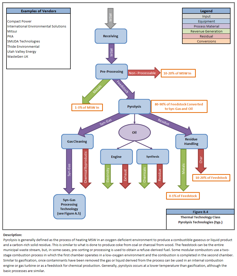
127 B-5
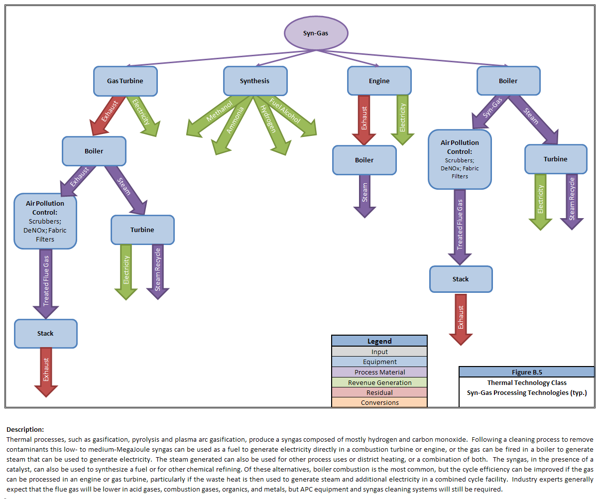
128 B-6

129 B-7

130 B-8
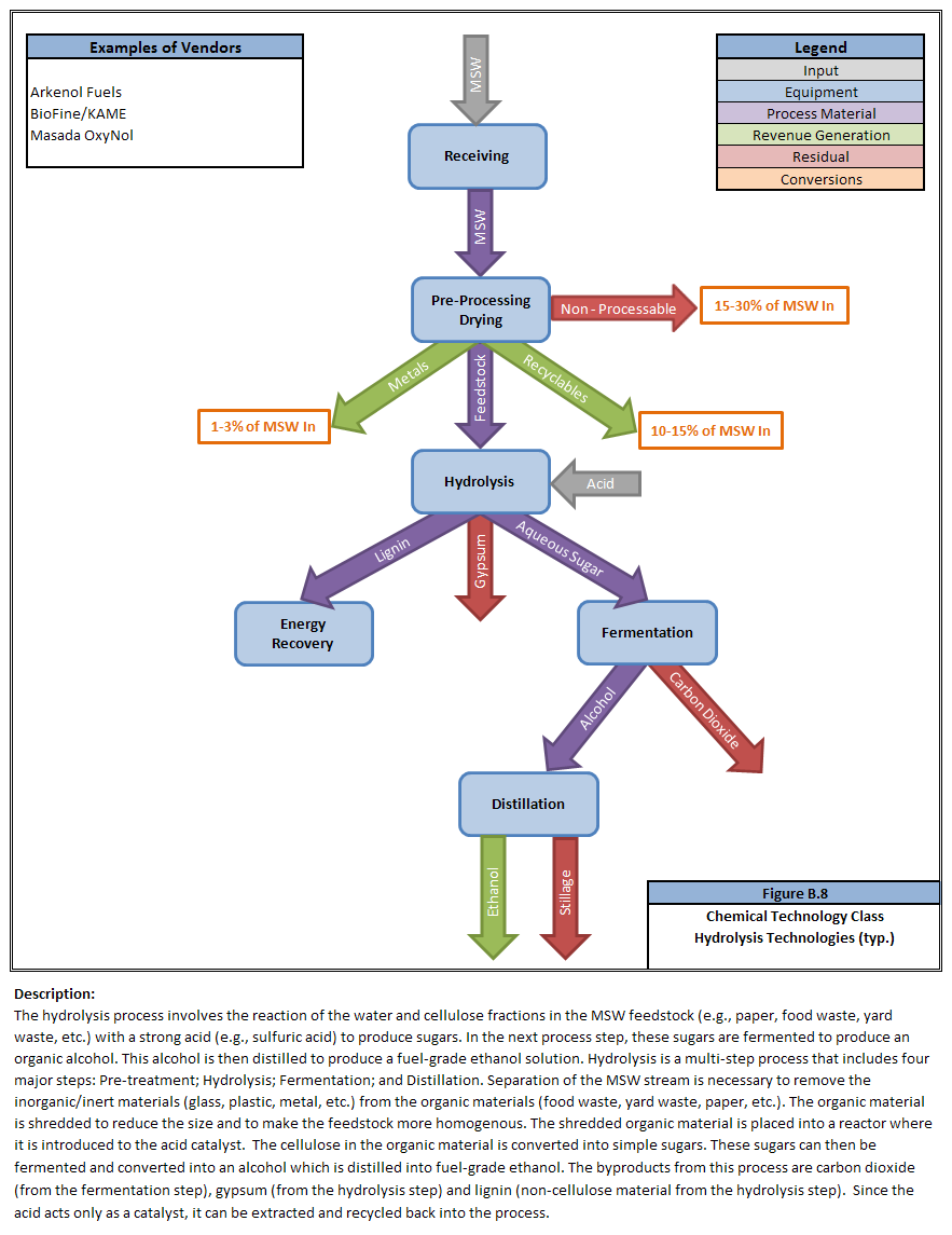
131 B-9
132 B-10

133 B-11

134 B-12
135 Appendix C: List of Available Technology Vendors C-1
136 Company Name Category Sub-Category Thermal Mass Burn Combustion Babcock & Wilcox Volund Thermal Mass Burn Combustion Consutech Thermal Mass Burn Combustion Detroit Stoker Thermal Mass Burn Combustion Ecomaine Thermal Mass Burn Combustion Enercon Systems Thermal Mass Burn Combustion Fisia Babcock Thermal Mass Burn Combustion Green Conversion Systems Thermal Mass Burn Combustion Keppel Seghers Thermal Mass Burn Combustion Martin GmbH (Covanta Energy) Thermal Mass Burn Combustion Pioneer Plus Thermal Mass Burn Combustion Steinmuller Thermal Mass Burn Combustion Takuma Thermal Mass Burn Combustion Veolia Environmental Services Thermal Mass Burn Combustion Von Roll Inova (Wheelabrator Technologies Inc. (Owned by Waste Management Inc.)) Thermal Thermal Mass Burn Combustion Fluidized Bed Combustion Ebara Corporation (ICFB Technologies) Thermal Fluidized Bed Combustion Environmental Products of Idaho Thermal Fluidized Bed Combustion Foster Wheeler Thermal Fluidized Bed Combustion Thermal Gasification Abengoa Thermal Gasification Agricultural Waste Solutions Thermal Gasification Biogen Power (Energos) Thermal Gasification Biogold Fuels Corp. Thermal Gasification Brightstar Environmental Thermal Gasification Carbontech LLC Thermal Gasification Chemrec Thermal Gasification Chiptec Thermal Gasification C-2
137 Company Name Category Sub-Category Choren Industries Thermal Gasification Coaltec Energy Thermal Gasification Community Power Corp (Energeon) Thermal Gasification Coskata Thermal Gasification Costich Company Thermal Gasification Dynecology Thermal Gasification Ebara Corporation (ICFG Technology) Thermal Gasification Ebara Corporation (TwinRec Gasification and Ash Melting Technology) Thermal Gasification Ecosystem Projects Thermal Gasification EcoTech Fuels, LLC Thermal Gasification Ener G Holdings Plc (Energos) Thermal Gasification Energy Products of Idaho (EPI) Thermal Gasification Enerkem Thermal Gasification EnerTech Environmental Thermal Gasification Enerwaste International Corp. Thermal Gasification Envirepel Thermal Gasification ForeverGreen Enterprises Thermal Gasification Freedom Renewable Energy Corp. Thermal Gasification Global Environmental Energy Corp. (GEECF) Thermal Gasification Global Warming Prevention Technologies Thermal Gasification Green Energy Corp Thermal Gasification Greey CTS (RES) Thermal Gasification Heuristic Engineering Inc. Thermal Gasification ILS Partners/pyromx Thermal Gasification Interstate Waste Technologies (Thermoselect) Thermal Gasification Jov Theodor Somesfalean Thermal Gasification Kame/DePlano Thermal Gasification New Planet Energy (INEOS Bio) Thermal Gasification Nexterra Thermal Gasification C-3
138 Company Name Category Sub-Category Ntech Environmental Thermal Gasification OE Gasification (Organic Energy) Thermal Gasification Omnifuel/Downstream System (Omni) Thermal Gasification Organic Energy Inc. Thermal Gasification Precision Energy Services, Inc. Thermal Gasification Primenergy (RRA) Thermal Gasification PRM Energy Systems, Inc. Thermal Gasification Range Fuels Thermal Gasification Silvagas Thermal Gasification SOTA Corporation Thermal Gasification Taylor Biomass Energy Thermal Gasification Technip Thermal Gasification ThermoChem Recovery International Inc. Thermal Gasification Thermogenics Inc. Thermal Gasification Viresco Energy (CE-CERT) Thermal Gasification Vista International Thermal Gasification W2E USA Inc. Thermal Gasification WET Systems Thermal Gasification Whitten Group (Entech Renewable Energy) Thermal Gasification Ze-Gen Thermal Gasification Zia Metallurgical Processes, Inc. Thermal Gasification Emerald Power Corp (Enerkem) Thermal Gasification/Catalytic Enerkem Thermal Gasification/Catalytic Fulcrum Bioenergy Thermal Gasification/Catalytic Alico (BRI) Thermal Gasification/ Fermentation BioEngineering resources (BRI) Thermal Gasification/ Fermentation Brienergy Thermal Gasification/ Fermentation Balboa Pacific Thermal Gasification/Pyrolysis Biomass Engineering Ltd. Thermal Gasification/Pyrolysis C-4
139 Company Name Category Sub-Category Compact Power Thermal Gasification/Pyrolysis Energy Dynamics Corp. International Thermal Gasification/Pyrolysis GEM America Thermal Gasification/Pyrolysis Heat Transfer International Thermal Gasification/Pyrolysis Heuristic Engineering Inc. (EnvirOcycler) Thermal Gasification/Pyrolysis PKA Thermal Gasification/Pyrolysis The Hoskinson Group Thermal Gasification/Pyrolysis Thermal Pyrolysis Adherent Technologies Inc. Thermal Pyrolysis Blue Tower Energy Inc. Thermal Pyrolysis Brightstar Envionmental Thermal Pyrolysis CMTC Services Inc. Thermal Pyrolysis Conrad Industries Thermal Pyrolysis Dynamotive Energy Systems Thermal Pyrolysis Enercon Systems Thermal Pyrolysis Entropic Technologies Corp. Thermal Pyrolysis GEM Canada Waste to Energy Inc. Thermal Pyrolysis Graveson Energy Management Thermal Pyrolysis International Environmental Solutions Thermal Pyrolysis Mitsui Thermal Pyrolysis Pan American Resources Thermal Pyrolysis PKA Thermal Pyrolysis Red Lion Bio-Energy Thermal Pyrolysis Rentech Inc. (Rentech-SilvaGas) Thermal Pyrolysis SMUDA Technologies Thermal Pyrolysis Splainex Ecosystems Ltd./ PLEQ GmbH/ Splainex TechTrade GmbH Thermal Pyrolysis Techtrade (WasteGen) Thermal Pyrolysis THIDE Environmental Thermal Pyrolysis Utah Valley Energy Thermal Pyrolysis C-5
140 Company Name Category Sub-Category Pyromex Thermal Pyrolysis/Hydrolysis Thermal Plasma Arc Gasification AdaptiveARC Thermal Plasma Arc Gasification Advanced Plasma Power Thermal Plasma Arc Gasification Alter NRG Thermal Plasma Arc Gasification Coronal LLC Thermal Plasma Arc Gasification EnviroArcTechnologies Thermal Plasma Arc Gasification Global Energy Solutions Thermal Plasma Arc Gasification GSB Technologies Thermal Plasma Arc Gasification Integrated Environmental Technologies Thermal Plasma Arc Gasification Jefferson Renewable Energy Thermal Plasma Arc Gasification MPM Technologies (Skygas) Thermal Plasma Arc Gasification Peat Int./Menlo Int. Thermal Plasma Arc Gasification Phoenix Solutions Co. Thermal Plasma Arc Gasification Plasco Energy Group Thermal Plasma Arc Gasification Plasma Environmental Technologies Inc. Thermal Plasma Arc Gasification Plasma Waste Recycling Inc. Thermal Plasma Arc Gasification Pyrogenesis Canada Inc. Thermal Plasma Arc Gasification Rigel Resource Recovery and Conversion Company Thermal Plasma Arc Gasification Solena Group Thermal Plasma Arc Gasification Startech Environmental Corporation (c/o Pearl Earth Sciences) Thermal Plasma Arc Gasification USST Thermal Plasma Arc Gasification Vitruvian Resources Inc. (Power Energy Fuels Inc.) Thermal Plasma Arc Gasification Westinghouse Plasma Corp (GeoPlasma) Thermal Plasma Arc Gasification Thermal Other Crimson Renewable Energy Thermal Biodiesel, Biogas Elementa Group (formerly EnQuest Power) Thermal Steam Reformation C-6
141 Company Name Category Sub-Category Environmental Waste Int l Thermal Microwave - tires Hydrolve Thermal Thermal Drying Kearns Waste Sciences Group Thermal 2-Stage Rotary Kiln Incineration KMW Energy Systems Inc. Thermal Biomass Combustion Molecular Waste Technologies Thermal Microwave QSTV Quantum Solutions Technology Ventures, Inc. Thermal Two Stage Combustion Sanimax Thermal Biodiesel VVBGC Waste2Energy Inc. Thermal Thermal Air-blown, High temp. gasification Batch Oxidation (Gasification) Zeros Technology Holding Thermal Thermal Oxidation Biological Anaerobic Digestion AAT BioGas Biological Anaerobic Digestion Allan Environmental Solutions Biological Anaerobic Digestion Arrow Ecology Biological Anaerobic Digestion Bekon Biological Anaerobic Digestion Bigadan Biological Anaerobic Digestion BioEnergy Solutions Biological Anaerobic Digestion BioRenewable Projects Biological Anaerobic Digestion Biowaste Treatment Technologies Ltd. (ArrowBio) Biological Anaerobic Digestion BTA International GmbH Biological Anaerobic Digestion CCI BioEnergy Inc. Biological Anaerobic Digestion Citec Biological Anaerobic Digestion EarthPower organics Biological Anaerobic Digestion East Bay MUD Biological Anaerobic Digestion EcoCorp Inc. Biological Anaerobic Digestion Enbasys Biotech Energy Biological Anaerobic Digestion Environmental Power Corp. Biological Anaerobic Digestion C-7
142 Company Name Category Sub-Category Grand Teton Enterprises Biological Anaerobic Digestion Greenfinch Biological Anaerobic Digestion Harvest Power Inc. Biological Anaerobic Digestion Herhof Gmbh Biological Anaerobic Digestion Hydromex Americas Biological Anaerobic Digestion ISKA GmbH (Global Renewables) Biological Anaerobic Digestion Kame/DePlano Biological Anaerobic Digestion Km Fiberight Biological Anaerobic Digestion Mitsui Engineering & Shipbuilding Inc. Biological Anaerobic Digestion Mustang Renewable Power Ventures Biological Anaerobic Digestion New Bio Biological Anaerobic Digestion Organic Waste Systems N.V. (OWS) Biological Anaerobic Digestion OrgaWorld Biological Anaerobic Digestion Presco Biological Anaerobic Digestion Quasar Energy Group Biological Anaerobic Digestion RenWaste Biological Anaerobic Digestion Sharp Energy, Inc. Biological Anaerobic Digestion Terrabon Inc. Biological Anaerobic Digestion Urbaser Biological Anaerobic Digestion Vagron Biological Anaerobic Digestion Valorga S.A.S. Biological Anaerobic Digestion Visiam Biological Anaerobic Digestion Wagner Consulting (Bekon) Biological Anaerobic Digestion ZAK (Zweckverband Abfallbehandlung Kahlenberg) Biological Anaerobic Digestion ZeroWaste Energy Biological Anaerobic Digestion Biological Aerobic Digestion American Bio-Tech Biological Aerobic Digestion Horstmann Recyclingtechnik GmbH Biological Aerobic Digestion Hotrot Exports Ltd. Biological Aerobic Digestion C-8
143 Company Name Category Sub-Category International Bio Recovery Corp. Biological Aerobic Digestion Mining Organics Biological Aerobic Digestion Real Earth Technologies Biological Aerobic Digestion Wright Environmental Management Inc. Biological Aerobic Digestion Chemical Hydrolysis Arkenol Fuels Chemical Hydrolysis BioFine/KAME Chemical Hydrolysis BlueFire Ethanol Chemical Hydrolysis Genahol Inc. Chemical Hydrolysis Genencor Chemical Hydrolysis Iogen Chemical Hydrolysis Masada Chemical Hydrolysis Pacific Ethanol Chemical Hydrolysis Chemical Thermal Depolymerization Confuel K2 Chemical Catalytic Depolymerization Green Power Inc. Chemical Catalytic Depolymerization KDV/AlphaKat Chemical Catalytic Depolymerization P3 Renewable Energy LLC Chemical Catalytic Depolymerization MadeInAmerica Fuel Chemical Microwave Depolymerization Changing World Technologies Chemical Thermal Depolymerization Mechanical Material Separation and Recovery Custom Conveyor Mechanical Conveyors Pro Baler Mechanical Conveyors United Conveyor Mechanical Conveyors WastAway Mechanical Mechanical Process CP Manufacturing Mechanical Screening Machine Mechanical Screening C-9
144 Company Name Category Sub-Category RRT Mechanical Screening VanDyke Mechanical Screening AmbientEco Group Inc. Cobb Creations Dongara Developments Energy Answers Orchid Environmental Ltd. Westroc Energy Mechanical Mechanical Mechanical Mechanical Mechanical Mechanical Mechanical Refuse Derived Fuel Production Refuse Derived Fuel Production Refuse Derived Fuel Production Refuse Derived Fuel Production Refuse Derived Fuel Production Refuse Derived Fuel Production Refuse Derived Fuel Production C-10
145 Appendix D: Potential Systems Process Flow Diagrams D-1
146 D-2
147 D-3
148 D-4
149 D-5
150 D-6
151 D-7
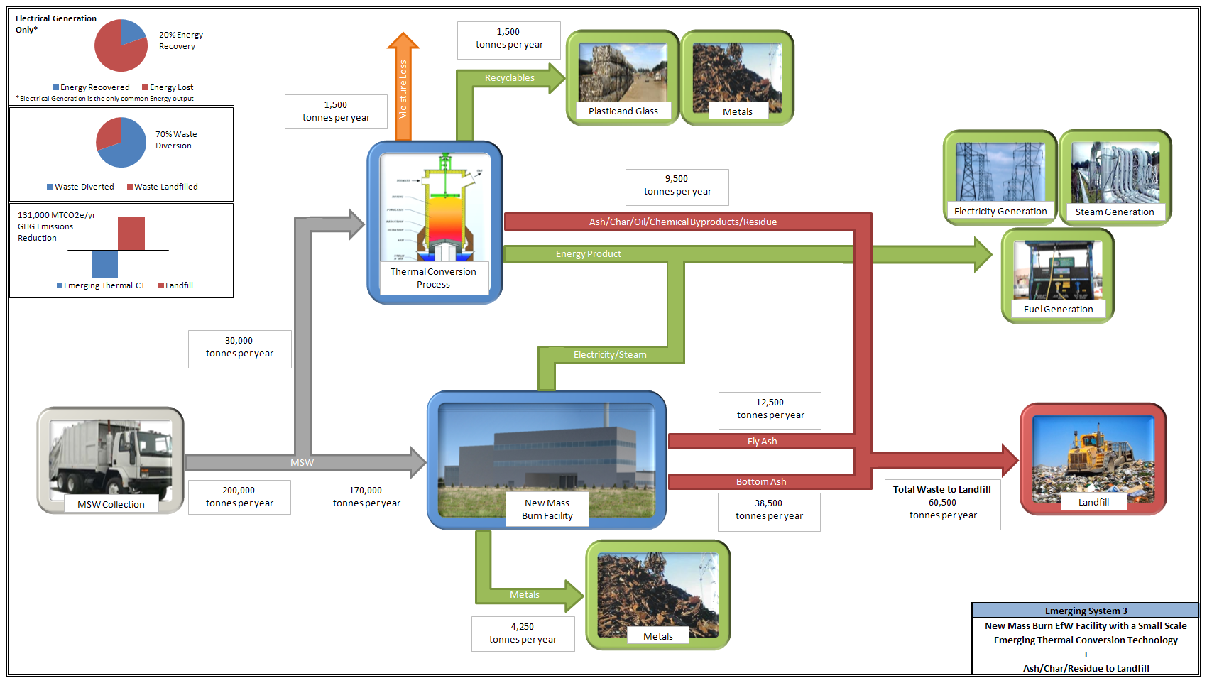
152 D-8
Waste a source of energy. Regional Solid Waste Management Plan Review: Engaging solutions for tomorrow. Incineration. Incineration
 Waste a source of energy Regional Solid Waste Management Plan Review: Engaging solutions for tomorrow Garbage School 301: Waste to Energy All organic materials contains energy Plant or animal based Plastics
6 CONSIDERATION OF ALTERNATIVES
 6 CONSIDERATION OF ALTERNATIVES 6.1.1 Schedule 4 of the Town and Country Planning (Environmental Impact Assessment) (Scotland) Regulations 2011 sets out the information for inclusion in Environmental Statements
Outlook on Integrated Gasification Combined Cycle (IGCC) Technology
 Technology") The IGCC Process: From Coal To Clean Electric Power Outlook on Integrated Gasification Combined Cycle (IGCC) Technology Testimony of Edward Lowe Gas Turbine-Combined Cycle Product Line Manager General
The IGCC Process: From Coal To Clean Electric Power Outlook on Integrated Gasification Combined Cycle (IGCC) Technology Testimony of Edward Lowe Gas Turbine-Combined Cycle Product Line Manager General
Energy from waste. Introduction. Legal status of this guideline. What is energy from waste? Draft guideline
 Draft guideline Energy from waste Publication 1549 September 2013 Authorised and published by EPA Victoria, 200 Victoria Street, Carlton Introduction As outlined in Getting full value: the Victorian Waste
SEATTLE STEAM COMPANY FREQUENTLY ASKED QUESTIONS
 SEATTLE STEAM COMPANY FREQUENTLY ASKED QUESTIONS What products/services does Seattle Steam provide? The company provides thermal energy (heat) produced at two central heating plants in downtown Seattle.
Assignment 8: Comparison of gasification, pyrolysis and combustion
 AALTO UNIVERSITY SCHOOL OF CHEMICAL TECHNOLOGY KE-40.4120 Introduction to biorefineries and biofuels Assignment 8: Comparison of gasification, pyrolysis and combustion Aino Siirala 309141 Assignment submitted
Thank you for being here today
 Thank you for being here today Presenter: Rob Smoot, a senior engineer for the Solid Waste division of Parks and Environmental Services here at Metro, a licensed Chemical Engineer with over 27 years working
Arecibo Resource Recovery Project
 Arecibo Resource Recovery Project Energy Answers International, Inc., through its subsidiary, Energy Answers Arecibo, LLC, is developing a 77 MW Resource Recovery Project to generate renewable energy and
THE PRACTICAL, PROVEN PATH TO GREEN ENERGY. RTP rapid thermal processing from Envergent Technologies
 THE PRACTICAL, PROVEN PATH TO GREEN ENERGY. RTP rapid thermal processing from Envergent Technologies RTP CONVERTS BIOMASS TO PYROLYSIS OIL FAST. Less than two seconds. That s all the time it takes to convert
RECOVERING RESOURCES FOR ALL. Integra North Energy Recovery Facility
 RECOVERING RESOURCES FOR ALL Integra North Energy Recovery Facility Integra North Energy Recovery Facility (ERF) was the first of its kind to be built in Hampshire and one of the leading examples of best
CNG, LNG, and Other Fuels from Landfill Gas ---Prospects for Future Development----
 CNG, LNG, and Other Fuels from Landfill Gas ---Prospects for Future Development---- California Biomass Collaborative 4 th Annual Forum March 28, 2007 Sacramento, California Patrick Sullivan SCS Engineers
RECOVERING RESOURCES FOR ALL. Integra South East Energy Recovery Facility
 RECOVERING RESOURCES FOR ALL Integra South East Energy Recovery Facility Integra South East Energy Recovery Facility (ERF) is the third of its kind to be built in Hampshire and is a leading example of
Category 5: Waste Generated in Operations
 5 Category 5: Waste Generated in Operations Category description C ategory 5 includes emissions from third-party disposal and treatment of waste generated in the reporting company s owned or controlled
Assessing the Changes Required by the Industrial Boiler MACT Regulations
 Technical Paper MS-17 Assessing the Changes Required by the Industrial Boiler MACT Regulations Authors: A.L. LeClair L.M. McDermitt Babcock & Wilcox Power Generation Group, Inc. Barberton, Ohio, U.S.A
Introduction to Waste Treatment Technologies. Contents. Household waste
 Contents Introduction to waste treatment technologies 3 Section 1: The treatment of recyclable waste 4 Bulking facilities 5 Materials Reclamation Facility (MRF) 6 Reuse and recycling centres 8 Composting
Biomass-to-Fuel-Cell Power For Renewable Distributed Power Generation
 Biomass-to-Fuel-Cell Power For Renewable Distributed Power Generation February 2013 The information contained in this document is derived from selected public sources. Ballard does not guarantee the accuracy
Chemical Engineer Office of Resource Conservation and Recovery
 Waste-to to-energy in the U.S. and Trends for the Future Jesse Miller Chemical Engineer Office of Resource Conservation and Recovery Tuesday, August 9, 2011 1 Presentation Outline ORCR Atiiti Activities
THE PRODUCTION OF ELECTRICITY FROM WOOD AND OTHER SOLID BIOMASS
 THE PRODUCTION OF ELECTRICITY FROM WOOD AND OTHER SOLID BIOMASS RTP TM /ADVANCED CYCLE VS. COMBUSTION STEAM CYCLES OR WHY NOT SIMPLY COMBUST? For decades, the only commercial option available for the production
Efficiency Metrics for CHP Systems: Total System and Effective Electric Efficiencies
 Efficiency Metrics for CHP Systems: Total System and Effective Electric Efficiencies Combined heat and power (CHP) is an efficient and clean approach to generating power and thermal energy from a single
10 Nuclear Power Reactors Figure 10.1
 10 Nuclear Power Reactors Figure 10.1 89 10.1 What is a Nuclear Power Station? The purpose of a power station is to generate electricity safely reliably and economically. Figure 10.1 is the schematic of
Energise your waste! EU legislation pushes for a reliable alternative to landfilling for residual waste. 13 th September 2011, Birmingham
 Energise your waste! EU legislation pushes for a reliable alternative to landfilling for residual waste 13 th September 2011, Birmingham Recycling & Waste Management (RWM) Exhibition Dr.ir. Johan De Greef
Appendix 5A: Natural Gas Use in Industrial Boilers
 Appendix 5A: Natural Gas Use in Industrial Boilers Industrial boilers consumed 2.1 Tcf of natural gas in 2006, accounting for 36% of total natural gas in manufacturing. 1 In this appendix, we provide further
Bill Maxwell, U.S. Environmental Protection Agency, OAQPS (C439-01)
") TO: Bill Maxwell, U.S. Environmental Protection Agency, OAQPS (C439-01) FROM: Jeffrey Cole, RTI International DATE: December 2003 SUBJECT: Methodology for Estimating Cost and Emissions Impact for Coal-
TO: Bill Maxwell, U.S. Environmental Protection Agency, OAQPS (C439-01) FROM: Jeffrey Cole, RTI International DATE: December 2003 SUBJECT: Methodology for Estimating Cost and Emissions Impact for Coal-
IWR Integrated Waste Recycling. Integrated System for treatment and recycling of Municipal Solid Waste
 IWR Integrated Waste Recycling Integrated System for treatment and recycling of Municipal Solid Waste 1 1. Introduction IWR is an integrated system, realised by different Italian companies, manufacturers
A Comparative Assessment of Commercial Technologies for Conversion of Solid Waste to Energy
 A Comparative Assessment of Commercial Technologies for Conversion of Solid Waste to Energy Bary Wilson, Ph.D. Neil Williams, Ph.D., P.E. Barry Liss, Ph.D., P.E. Brandon Wilson, Ph.D. Prepared for EnviroPower
Gasification as means of Waste-to-Energy - Main Parameters and application -
 Gasification as means of Waste-to-Energy - Main Parameters and application - 9 th ISWA Beacon Conference in Malm, Sweden 18 th NOV. 2015 Block 4: Gasification NIPPON STEEL & SUMIKIN ENGINEERING CO., LTD
Process Technology. Advanced bioethanol production and renewable energy generation from ligno-cellulosic materials, biomass waste and residues
 Process Technology Advanced bioethanol production and renewable energy generation from ligno-cellulosic materials, biomass waste and residues The INEOS Bio process technology produces carbon-neutral bioethanol
Developments and trends shaping the future for Waste-to- Energy technology suppliers
 Developments and trends shaping the future for Waste-to- Energy technology suppliers 21 st October 2015 Copenhagen, Denmark Edmund Fleck ESWET President 2 Contents 1. About ESWET 2. Introduction 3. Modern
Iron and Steel Manufacturing
 Pollution Prevention and Abatement Handbook WORLD BANK GROUP Effective July 1998 Iron and Steel Manufacturing Industry Description and Practices Steel is manufactured by the chemical reduction of iron
Energy From Waste or Waste-to-Energy. Pyromex. The Solution to Multiple Energy & Environmental Issues James Pfeiffer, CEM
 Energy From Waste or Waste-to-Energy Pyromex The Solution to Multiple Energy & Environmental Issues James Pfeiffer, CEM 1 Agenda Who is PowerHouse Energy What is Pyromex How Does Pyromex Work History of
COMPARISON OF PROCESS FLOWS: FLUID BED COMBUSTOR AND GLASSPACK
 COMPARISON OF PROCESS FLOWS: FLUID BED COMBUSTOR AND GLASSPACK PURPOSE The purpose of this document is to present the assumptions and calculations used to prepare Minergy Drawing 100-0204-PP00 (attached).
Waste to Energy. Anders Damgaard. Thanks to Jiri Hyks and Thomas H Christensen DTU for some slides
 Denmark (Thomas Astrup) Denmark (COWI) Waste to Energy Anders Damgaard Austria (CEWEP) Thanks to Jiri Hyks and Thomas H Christensen DTU for some slides Copyright Anders Damgaard & Morton A. Barlaz, NC
EFFICIENT ENERGY SUPPLY (ELECTRICITY AND DISTRICT HEAT) FOR THE CITY OF LINZ
 FOR THE CITY OF LINZ") Parallel session Producing more with less: Efficiency in Power Generation EFFICIENT ENERGY SUPPLY (ELECTRICITY AND DISTRICT HEAT) FOR THE CITY OF LINZ Johann Gimmelsberger Linz Strom GmbH EFFICIENT ENERGY
Parallel session Producing more with less: Efficiency in Power Generation EFFICIENT ENERGY SUPPLY (ELECTRICITY AND DISTRICT HEAT) FOR THE CITY OF LINZ Johann Gimmelsberger Linz Strom GmbH EFFICIENT ENERGY
Environment Impact Assessment of Thermal Power Plant for Sustainable Development
 International Journal of Environmental Engineering and Management. ISSN 2231-1319, Volume 4, Number 6 (2013), pp. 567-572 Research India Publications http://www.ripublication.com/ ijeem.htm Environment
ASME QRO Certification Program
 ASME QRO Certification Program ASME QRO Certification For Operators of Resource Recovery Facilities Applicant Information Table of Contents Table of Contents Page QRO Certification Overview...1 Types of
Well Positioned for the Future
 Dominion Generation Virginia City Hybrid Energy Center Well Positioned for the Future The Coal Institute July 13, 2015 Rick Boyd Manager of Fuel Origination & Operations 1 Dominion Profile Operating Segments
Biomass Issues. John Christopher Madole Associates, Inc. presentation to the Minnesota Department of Commerce September 12, 2007
 Biomass Issues John Christopher Madole Associates, Inc. presentation to the Minnesota Department of Commerce September 12, 2007 Biomass Issues Feedstocks-- Harvesting, Transporation & Storage Process Technology
This fact sheet provides an overview of options for managing solid
 What Is Integrated Solid Waste Management? This fact sheet provides an overview of options for managing solid waste, identifies the important issues you should consider when planning for solid waste management,
PE9.4 Corrected Report
 PE9.4 Corrected Report STAFF REPORT ACTION REQUIRED Toronto s 2013 Greenhouse Gas Inventory Date: December 17, 2015 To: From: Wards: Reference Number: Parks and Environment Committee Chief Corporate Officer
David Mezzacappa, P.E. SCS Engineers Contractor to U.S. EPA on LMOP
 LMOP Workshop: LFG Collection & LFG Energy Technologies David Mezzacappa, P.E. SCS Engineers Contractor to U.S. EPA on LMOP Introduction Goal convert LFG into a useful energy form Technologies include:
Birmingham City University / Students Union Aspects and Impacts Register. Waste. Impacts description
 Birmingham City University / Students Union and Impacts Register Waste Production of non - hazardous waste Production of hazardous waste Storage of non - hazardous waste Potential for waste to be disposed
OCC EnErgy POliCiEs 2011-2012
 OCC Energy POlicies 2011-2012 OCC Energy POlicies 2011-2012 AGENDA 1 1 2 2 3 3 4 4 5 Introduction Long Term Planning: Affordable, Reliable and Abundant Energy Supply Electricity Market Development and
Waste to Energy in Düsseldorf. for a clean city.
 Waste to Energy in Düsseldorf for a clean city. Waste Management in Düsseldorf. Düsseldorf s public utilities company known as Stadtwerke Düsseldorf operates a waste to energy plant (WtE) that has been
Comparison of Select Materials and Energy Recycling Scenarios
 Final Report Comparison of Select Materials and Energy Recycling Scenarios City and County of Honolulu Department of Environmental Services April 2007 R. W. BECK, INC. COMPARISON OF SELECT MATERIALS AND
Tutkimuksen merkitys menestyvässä liiketoiminnassa- Innovaatiosta tuotteeksi
 Tutkimuksen merkitys menestyvässä liiketoiminnassa- Innovaatiosta tuotteeksi Matti Rautanen Manager, External Networks, Power-wide R&D Tutkimuksella tulevaisuuteen- seminaari Kaukolämpöpäivät, Kuopio 29.8.2013
ENVIRONMENTAL LIFE-CYCLE COMPARISONS OF RECYCLING, LANDFILLING, AND INCINERATION: A Review of Recent Studies
 Annu. Rev. Energy Environ. 1996. 21:191 237 Copyright c 1996 by Annual Reviews Inc. All rights reserved ENVIRONMENTAL LIFE-CYCLE COMPARISONS OF RECYCLING, LANDFILLING, AND INCINERATION: A Review of Recent
Hybrid Power Generations Systems, LLC
 Coal Integrated Gasification Fuel Cell System Study Pre-Baseline Topical Report April 2003 to July 2003 Gregory Wotzak, Chellappa Balan, Faress Rahman, Nguyen Minh August 2003 Performed under DOE/NETL
Renewable Energy from Biomass. Opportunities in London and Area? Eric Rosen
 Renewable Energy from Biomass Opportunities in London and Area? Eric Rosen KMW ENERGY INC. LONDON, ONTARIO Tel: (519) 686-1771 www.kmwenergy.com Company Background Long History in designing bioenergy systems.
State of the Art (SOTA) Manual for Boilers and Process Heaters
 Manual for Boilers and Process Heaters") State of the Art (SOTA) Manual for Boilers and Process Heaters Original Date: July 1997 Revision Date: February 22, 2004 State of New Jersey Department of Environmental Protection Air Quality Permitting
State of the Art (SOTA) Manual for Boilers and Process Heaters Original Date: July 1997 Revision Date: February 22, 2004 State of New Jersey Department of Environmental Protection Air Quality Permitting
Maximising recycling rates tackling residuals
 September 2002 Briefing Maximising recycling rates tackling residuals Background Friends of the Earth is an international organisation with over 70 member groups across the World. The majority of these
MODERN TECHNOLOGIES FOR ENERGY AND MATERIAL RECOVERY FROM WASTE. Tomáš Rohal, Business Development CEEI 10-Oct-2013
 MODERN TECHNOLOGIES FOR ENERGY AND MATERIAL RECOVERY FROM WASTE Tomáš Rohal, Business Development CEEI 10-Oct-2013 1 Who We Are Central Europe Engineering & Investment (CEEI) offers the state-of-the-art
GENERATION TECHNOLOGY ASSESSMENT
 SPO PLANNING ANALYSIS GENERATION TECHNOLOGY ASSESSMENT Technology Cost & Performance Milestone 2 Public Technical Conference OCTOBER 30, 2014 NOTE: ALL IRP MATERIALS ARE PRELIMINARY & SUBJECT TO CHANGE
B0401 Abstract 029 Oral Presentation Session B04 Innovative Applications and Designs - Tuesday, July 1, 2008 16:00 h
 Reference System for a Power Plant Based on Biomass Gasification and SOFC Richard Toonssen, Nico Woudstra, Adrian H.M. Verkooijen Delft University of Technology Energy Technology, Process & Energy department
GUIDELINES FOR PROCESSING AND USING REFUSE DERIVED FUEL (RDF) IN CEMENT INDUSTRY
 IN CEMENT INDUSTRY") 1 GUIDELINES FOR PROCESSING AND USING REFUSE DERIVED FUEL (RDF) IN CEMENT INDUSTRY August, 2012 Government of Pakistan Pakistan Environmental Protection Agency (Ministry of Climate Change) Islamabad 2
1 GUIDELINES FOR PROCESSING AND USING REFUSE DERIVED FUEL (RDF) IN CEMENT INDUSTRY August, 2012 Government of Pakistan Pakistan Environmental Protection Agency (Ministry of Climate Change) Islamabad 2
SLMA Meeting. Boiler MACT and Related Rules. Atlanta, GA March 2, 2011. Martin Rollins, P. E. H. M. Rollins Company, Inc. Gulfport, Mississippi
 SLMA Meeting Atlanta, GA March 2, 2011 Boiler MACT and Related Rules Martin Rollins, P. E. H. M. Rollins Company, Inc. Gulfport, Mississippi Boiler MACT and Related Rules EPA Had Requested 15 Month Delay
DELIVERING THE BIOENERGY TRIPLE BOTTOM LINE TO THE GLOBAL COMMUNITY
 DELIVERING THE BIOENERGY TRIPLE BOTTOM LINE TO THE GLOBAL COMMUNITY Ralph E. H. Sims 2 and Keith Richards 1 1 Thames Valley Energy Ltd., Newbury, England. 2 Centre for Energy Research, Massey University,
Municipal waste management in Austria
 Municipal waste management in Austria Prepared by Márton Herczeg ETC/SCP February 2013 EEA project manager Almut Reichel Author affiliation Márton Herczeg, Copenhagen Resource Institute, http://www.cri.dk/
Study Plan. MASTER IN (Energy Management) (Thesis Track)
 (Thesis Track)") Plan 2005 T Study Plan MASTER IN (Energy Management) (Thesis Track) A. General Rules and Conditions: 1. This plan conforms to the regulations of the general frame of the programs of graduate studies. 2.
Plan 2005 T Study Plan MASTER IN (Energy Management) (Thesis Track) A. General Rules and Conditions: 1. This plan conforms to the regulations of the general frame of the programs of graduate studies. 2.
PHARMACEUTICAL AND CHEMICAL WASTE MANAGEMENT
 Medicines and Medical Devices Agency of Serbia PHARMACEUTICAL AND CHEMICAL WASTE MANAGEMENT Ivana Bozic, MSc Health, Safety and Environment ISWA Beacon Conference, Novi Sad, 08 10 December 2010 458, Vojvode
Nu G Medical Waste System Technology (Pyrolysis / Thermal Decomposition)
") Product Description: Nu G Medical Waste System Technology (Pyrolysis / Thermal Decomposition) The NU G System uses pyrolysis thermal decomposition to treat infectious wastes typically generated in hospitals.
Product Description: Nu G Medical Waste System Technology (Pyrolysis / Thermal Decomposition) The NU G System uses pyrolysis thermal decomposition to treat infectious wastes typically generated in hospitals.
Our Environmental Protection Plan RECYCLING CAPABILITIES AND ENVIRONMENTAL ACCOMPLISHMENTS
 Our Environmental Protection Plan RECYCLING CAPABILITIES AND ENVIRONMENTAL ACCOMPLISHMENTS WHO WE ARE Since day one, East Penn has made safe recycling an everyday practice. East Penn opened its doors as
of 11,000 households Steam temperature, boiler 400 C Steam pressure, boiler Incineration temperature 1,100 C
 refuse collection energy incineration waste REFA Waste-to-Energy Plant from waste to energy REFA Waste-to-Energy Plant - a Facility for waste incineration and energy generation REFA Waste-to-Energy Plant
A Green Idea. Reclaiming Urban Wood Waste And Urban Forest Debris. For Fuel/Combustion & Renewable Energy
 A Green Idea Reclaiming Urban Wood Waste And Urban Forest Debris For Fuel/Combustion & Renewable Energy Presentation Edward Kalebich Chief Operating Officer Robbins Community Power Facility located Chicago
Renewable Energy Research
 Renewable Energy Research Georgia Power and Southern Company have been active in renewable energy research for many years. Over the last five years we have invested six million dollars in renewable energy
A clean energy solution from cradle to grave
 Environmental Product Declaration A clean energy solution from cradle to grave Offshore wind power plant employing SWT-6.0-154 siemens.com / wind 2 Assessing the performance of a wind power plant The environmental
2050 LOW CARBON ECONOMY Executive Summary THE EUROPEAN CEMENT ASSOCIATION
 The role of CEMENT in the 2050 LOW CARBON ECONOMY Executive Summary THE EUROPEAN CEMENT ASSOCIATION Concrete is the third most used substance in the world after air and water, a staple of modern life and
ENVIRONMENTAL EXTERNALITIES FROM LANDFILL DISPOSAL AND INCINERATION OF WASTE
 International Journal of Advanced Research in Engineering and Technology (IJARET) Volume 7, Issue 1, Jan-Feb 2016, pp. 47-53, Article ID: IJARET_07_01_006 Available online at http://www.iaeme.com/ijaret/issues.asp?jtype=ijaret&vtype=7&itype=1
Use of Substitute Fuels in Large Combustion Plants (LCPs)
") Use of Substitute Fuels in Large Combustion Plants (LCPs) By Pat Swords Content of the Presentation What are substitute fuels What is the experience to date with these fuels What are the regulatory implications
Use of Substitute Fuels in Large Combustion Plants (LCPs) By Pat Swords Content of the Presentation What are substitute fuels What is the experience to date with these fuels What are the regulatory implications
Biomass Boiler House Best Practices. Irene Coyle & Fernando Preto CanmetENERGY
 Biomass Boiler House Best Practices Irene Coyle & Fernando Preto CanmetENERGY Growing the Margins London, Ontario March 2010 The Biomass & Renewables Group of Industrial Innovation Group (IIG) of CanmetENERGY
Nonrenewable Natural Gas. Natural Gas Basics. How Was Natural Gas Formed?
 Did You Know? Because natural gas is colorless, odorless, and tasteless, mercaptan (a chemical that smells like sulfur) is added before distribution, to give it a distinct unpleasant odor (it smells like
Biomass Renewable Energy from Plants and Animals
 Renewable Biomass Biomass Basics Biomass Renewable Energy from Plants and Animals Biomass is organic material made from plants and animals. Biomass contains stored energy from the sun. Plants absorb the
TRIAL CHEMICAL CLEANING OF FOULED APH BASKETS
 TRIAL CHEMICAL CLEANING OF FOULED APH BASKETS Dr. Abhay Kumar Sahay, AGM(CC OS) Bijay Manjul, AGM( Operation) Kahalgaon Boiler has three inputs Steam generator 1. WATER 2. COAL 3. AIR Burner Air preheater
Renewable Gas Vision for a Sustainable Gas Network. A paper by National Grid
 Renewable Gas Vision for a Sustainable Gas Network A paper by National Grid Executive Summary Renewable Gas also known as biomethane, is pipeline quality gas derived from biomass that is fully interchangeable
WASTE MANAGEMENT UTILITY BUSINESS PLAN 2016-2018
 WASTE MANAGEMENT UTILITY BUSINESS PLAN 2016-2018 Kennedale Eco Station design rendering CR_2495 Attachment 1 TABLE OF CONTENTS p. 3 INTRODUCTION p. 4 STRATEGIC FRAMEWORK VISION MISSION 30-YEAR WASTE MANAGEMENT
The Fate of Ammonia and Mercury in the Carbon Burn-Out (CBO ) Process
 Process") The Fate of Ammonia and Mercury in the Carbon Burn-Out (CBO ) Process Vincent M Giampa Progress Materials, Inc., One Progress Plaza, St. Petersburg, Florida 33701 KEYWORDS: mercury, ammonia, carbon burn-out,
The Fate of Ammonia and Mercury in the Carbon Burn-Out (CBO ) Process Vincent M Giampa Progress Materials, Inc., One Progress Plaza, St. Petersburg, Florida 33701 KEYWORDS: mercury, ammonia, carbon burn-out,
Growing your greenhouse business faster with gas engines.
 Growing your greenhouse business faster with gas engines. Our combined heat and power engines can increase the efficiency and profitability of your greenhouses. Because it s not just your plants that need
RENEWABLE ENERGY. The Sustainable Energy Plant.
 RENEWABLE ENERGY The Sustainable Energy Plant. 1. 7. 2. 6. 3. 5. 4. How landfill-gas-to-energy works 1. Creating energy from landfill gas begins with collection. When taking into account homes, restaurants,
How To Make Calcium Carbide
 11.4 Calcium Carbide Manufacturing 11.4.1 General Calcium carbide (CaC 2 ) is manufactured by heating a lime and carbon mixture to 2000 to 2100 C (3632 to 3812 F) in an electric arc furnace. At those temperatures,
Development of Coal Gasification System for Producing Chemical Synthesis Source Gas
 27 Development of Coal Gasification System for Producing Chemical Synthesis Source Gas TAKAO HASHIMOTO *1 KOICHI SAKAMOTO *1 KATSUHIRO OTA *2 TAKASHI IWAHASHI *3 YUUICHIROU KITAGAWA *4 KATSUHIKO YOKOHAMA
JASE-world Waste to Energy Sub WG Masanori Tsukahara Hitachi Zosen Corporation 2012.11.14
 Presentation of Japanese technology of waste to energy JASE-world Waste to Energy Sub WG Masanori Tsukahara Hitachi Zosen Corporation 2012.11.14 1 JASE-W established in Oct 2008 Introduction of JASE-world
Nitrogenous Fertilizer Plants
 Pollution Prevention and Abatement Handbook WORLD BANK GROUP Effective July 1998 Nitrogenous Fertilizer Plants Industry Description and Practices This document addresses the production of ammonia, urea,
WASTES INCINERATION PLANTS
 WASTES INCINERATION PLANTS CRITERIA OF WASTE CLASSIFICATION FROM ENERGY UTILISATION STANDPOINT MAJOR TYPES OF WASTES 1. Municipal 2. Medical 3. Industrial 4. Sewage sladge 5. Agriculture wastes 6. Building
GE Power & Water Water & Process Technologies. Water Treatment Solutions for Unconventional Gas
 GE Power & Water Water & Process Technologies Water Treatment Solutions for Unconventional Gas Addressing Today s Challenges Today, corporations, individuals and governmental bodies alike are focused on
University of Iowa Power Plant
 University of Iowa Power Plant Contents Purpose... 2 History... 3 Cogeneration... 6 Boilers... 7 Environmental Impact... 10 Steam Turbine Generators... 12 Modernization... 14 Biomass Fuel Initiative...
It s time for H.E.R.O. Energy Saving Strategy for. Tunnel & Shuttle Kilns
 Energy Saving Strategy for Tunnel & Shuttle Kilns SANITARY WARE 1 Introduction The application of the Kyoto protocol and the effects of the recent energy crisis, have highlighted just how important it
Condensing Economizers Workshop Enbridge Gas, Toronto. MENEX Boiler Plant Heat Recovery Technologies. Prepared by: Jozo Martinovic, M A Sc, P Eng
 Condensing Economizers Workshop Enbridge Gas, Toronto MENEX Boiler Plant Heat Recovery Technologies Prepared by: Jozo Martinovic, M A Sc, P Eng MENEX Innovative Solutions May 15, 2008 MENEX INC. 683 Louis
Date: 12 th December 2013
 Mr Ross Taylor Parsons Brinckerhoff Amber Court William Armstrong Drive Newcastle Upon Tyne NE4 7YQ Our ref: EPR/FP3838EB/A001 Your ref: EPR/FP3838EB/RFI Date: 12 th December 2013 Dear Mr Taylor We need
CNG Fueling Developments and Renewable Conversion to RNG Technology and Update on a RNG Fleet
 CNG Fueling Developments and Renewable Conversion to RNG Technology and Update on a RNG Fleet NY State Chapter of SWANA, Albany. NY. June 13, 2013 Bernard Sheff, PE, Vice President Anaergia Inc. Agenda
PALM BEACH COUNTY WTE EXPANSION MODEL
 PALM BEACH COUNTY WTE EXPANSION MODEL Thomas M. Henderson Malcolm Pirnie, Inc. West Palm Beach, Florida, USA Leah K. Richter Malcolm Pirnie, Inc. Plantation, Florida, USA ABSTRACT Palm Beach County (Florida)
Continuous flow direct water heating for potable hot water
 Continuous flow direct water heating for potable hot water An independently produced White Paper for Rinnai UK 2013 www.rinnaiuk.com In the 35 years since direct hot water systems entered the UK commercial
How To Evaluate Cogeneration
 Power topic #7018 Technical information from Cummins Power Generation Inc. Evaluating cogeneration for your facility: A look at the potential energy-efficiency, economic and environmental benefits > White
Sewage sludge treatment with oxygen enrichement and oxyfuel combustion in CFBC - new pilot plant results
 Sewage sludge treatment with oxygen enrichement and oxyfuel combustion in CFBC - new pilot plant results 64 TH IEA FLUIDIZED BED CONVERSION MEETING Naples 3 rd of June, 2012 Authors: David Wöß, Gregor
FURNACEPHOSPHORUS AND PHOSPHORICACID PROCESS ECONOMICS PROGRAM. Report No. 52. July 1969. A private report by. the
 Report No. 52 FURNACEPHOSPHORUS AND PHOSPHORICACID by GEORGE E. HADDELAND July 1969 A private report by. the PROCESS ECONOMICS PROGRAM STANFORD RESEARCH INSTITUTE MENLO PARK, CALIFORNIA CONTENTS 1 INTRODUCTION........................
LANDFILL GAS TO ENERGY- COMBINED ENGINE AND ORC-PROCESS
 LANDFILL GAS TO ENERGY- COMBINED ENGINE AND ORC-PROCESS Dr Petri Kouvo Helsinki Region Environmental Services Authority THIRD INTERNATIONAL SYMPOSIUM ON ENERGY FROM BIOMASS AND WASTE Venice, Italy 8-11
Description of Thermal Oxidizers
 Description of Thermal Oxidizers NESTEC, Inc. is a full service equipment supplier specializing in solutions for plant emission problems. The benefit in working with NESTEC, Inc. is we bring 25+ years
Making Coal Use Compatible with Measures to Counter Global Warming
 Making Use Compatible with Measures to Counter Global Warming The J-POWER Group is one of the biggest coal users in Japan, consuming approximately 2 million tons of coal per year at eight coal-fired power
How To Gasify Wood And Agriculture Biomass
 Gasification: An Old Technology for a New Use Sponsored by: Joel Tallaksen, Biomass Coordinator West Central Research & Outreach Center, University of Minnesota Fueling the Future: The Role of Woody and
APPLICATION FOR EXEMPTION Assessing Authority
 TO: Combined Request for Pollution Control and Recycling Property Tax Exemption and Iowa Code Section 427.1 (19) APPLICATION FOR EXEMPTION Assessing Authority IMPORTANT: The application should be filed
Carbon Dioxide Membrane Separation for Carbon Capture using Direct FuelCell Systems
 Carbon Dioxide Membrane Separation for Carbon Capture using Direct FuelCell Systems DFC Technology Used as Electrochemical Membrane for CO 2 Purification and Capture during Power Generation FCE s Direct