Copyright Notice: Disclaimer: CALIFORNIA, USA ONLY. Version 1.0 Published May 2014 Copyright 2014 ASRock INC. All rights reserved.
|
|
|
- Brianne Lawson
- 8 years ago
- Views:
Transcription
1 User Manual

2 Version 1.0 Published May 2014 Copyright 2014 ASRock INC. All rights reserved. Copyright Notice: No part of this documentation may be reproduced, transcribed, transmitted, or translated in any language, in any form or by any means, except duplication of documentation by the purchaser for backup purpose, without written consent of ASRock Inc. Products and corporate names appearing in this documentation may or may not be registered trademarks or copyrights of their respective companies, and are used only for identiication or explanation and to the owners beneit, without intent to infringe. Disclaimer: Speciications and information contained in this documentation are furnished for informational use only and subject to change without notice, and should not be constructed as a commitment by ASRock. ASRock assumes no responsibility for any errors or omissions that may appear in this documentation. With respect to the contents of this documentation, ASRock does not provide warranty of any kind, either expressed or implied, including but not limited to the implied warranties or conditions of merchantability or itness for a particular purpose. In no event shall ASRock, its directors, oicers, employees, or agents be liable for any indirect, special, incidental, or consequential damages (including damages for loss of proits, loss of business, loss of data, interruption of business and the like), even if ASRock has been advised of the possibility of such damages arising from any defect or error in the documentation or product. his device complies with Part 15 of the FCC Rules. Operation is subject to the following two conditions: (1) this device may not cause harmful interference, and (2) this device must accept any interference received, including interference that may cause undesired operation. CALIFORNIA, USA ONLY he Lithium battery adopted on this motherboard contains Perchlorate, a toxic substance controlled in Perchlorate Best Management Practices (BMP) regulations passed by the California Legislature. When you discard the Lithium battery in California, USA, please follow the related regulations in advance. Perchlorate Material-special handling may apply, see perchlorate ASRock Website:

3 he terms HDMI and HDMI High-Deinition Multimedia Interface, and the HDMI logo are trademarks or registered trademarks of HDMI Licensing LLC in the United States and other countries. Manufactured under license under U.S. Patent Nos: 5,956,674; 5,974,380; 6,487,535; 7,003,467 & other U.S. and worldwide patents issued & pending. DTS, the Symbol, & DTS and the Symbol together is a registered trademark & DTS Connect, DTS Interactive, DTS Neo:PC are trademarks of DTS, Inc. Product includes sotware. DTS, Inc., All Rights Reserved.

4 Contents Chapter 1 Introduction Package Contents Speciications Motherboard Layout I/O Panel 10 Chapter 2 Installation Installing the CPU Installing the CPU Fan and Heatsink Installing Memory Modules (DIMM) Expansion Slots (PCI Express Slots) Jumpers Setup Onboard Headers and Connectors Smart Switches Dr. Debug SLI TM and Quad SLI TM Operation Guide Installing Two SLI TM -Ready Graphics Cards Driver Installation and Setup CrossFireX TM, 3-Way CrossFireX TM and Quad CrossFireX TM Operation Guide Installing Two CrossFireX TM -Ready Graphics Cards Installing Three CrossFireX TM -Ready Graphics Cards Driver Installation and Setup M.2_SSD (NGFF) Module Installation Guide 35

5 2.12 HDD Saver Cable Installation Guide 38 Chapter 3 Software and Utilities Operation Installing Drivers F-Stream Killer Network Manager Installing Killer Network Manager Using Killer Network Manager Intel Rapid Start Technology Intel Smart Connect Technology ASRock Cloud (Intel I218V) ASRock Cloud (Qualcomm Atheros Killer TM E2200 Series) ASRock APP Shop Start SBX Pro Studio Technology XSplit Broadcaster Live Streaming Your Gameplay Recording Your Gameplay 99 Chapter 4 UEFI SETUP UTILITY Introduction UEFI Menu Bar Navigation Keys Main Screen OC Tweaker Screen Advanced Screen 112

6 4.4.1 CPU Coniguration Chipset Coniguration Storage Coniguration Intel Rapid Start Technology Intel Smart Connect Technology Intel Thunderbolt Super IO Coniguration ACPI Coniguration USB Coniguration Trusted Computing Tools Hardware Health Event Monitoring Screen Boot Screen Security Screen Exit Screen 137

7 Fatal1ty Z97 Professional Series Chapter 1 Introduction hank you for purchasing ASRock Fatal1ty Z97 Professional Series motherboard, a reliable motherboard produced under ASRock s consistently stringent quality control. It delivers excellent performance with robust design conforming to ASRock s commitment to quality and endurance. In this documentation, Chapter 1 and 2 contains the introduction of the motherboard and step-by-step installation guides. Chapter 3 contains the operation guide of the sotware and utilities. Chapter 4 contains the coniguration guide of the BIOS setup. Because the motherboard speciications and the BIOS sotware might be updated, the content of this documentation will be subject to change without notice. In case any modiications of this documentation occur, the updated version will be available on ASRock s website without further notice. If you require technical support related to this motherboard, please visit our website for speciic information about the model you are using. You may ind the latest VGA cards and CPU support list on ASRock s website as well. ASRock website Package Contents ASRock Fatal1ty Z97 Professional Series Motherboard (ATX Form Factor) ASRock Fatal1ty Z97 Professional Series Quick Installation Guide ASRock Fatal1ty Z97 Professional Series Support CD 4 x Serial ATA (SATA) Data Cables (Optional) 1 x I/O Panel Shield 1 x ASRock SLI_Bridge_2S Card 1 x HDD Saver Cable 1 x Screw for M.2_SSD (NGFF) Socket 3 1 x Screw for mini-pcie Slot 1

8 1.2 Speciications Platform ATX Form Factor High Density Glass Fabric PCB CPU Supports 5 th Generation, New 4 th and 4 th Generation Intel Core i7/i5/i3/pentium /Celeron Processors (Socket 1150) Digi Power design 12 Power Phase design Supports Intel Turbo Boost 2.0 Technology Supports Intel K-Series unlocked CPUs Supports ASRock BCLK Full-range Overclocking Chipset Intel Z97 Memory Dual Channel DDR3 Memory Technology 4 x DDR3 DIMM Slots Supports DDR (OC)/2933 (OC)/2800(OC)/2400(OC)/2133(OC)/1866 (OC)/1600/ 1333/1066 non-ecc, un-bufered memory Max. capacity of system memory: 32GB (see CAUTION) Supports Intel Extreme Memory Proile (XMP) 1.3 / 1.2 Expansion Slot 3 x PCI Express 3.0 x16 Slots (PCIE2/PCIE4/PCIE6: single at x16 (PCIE2); dual at x8 (PCIE2) / x8 (PCIE4); triple at x8 (PCIE2) / x4 (PCIE4) / x4 (PCIE6) 1 x PCI Express 2.0 x16 Slot (PCIE1: x4 mode) 2 x PCI Express 2.0 x1 Slots 1 x mini-pci Express Slot Supports AMD Quad CrossFireX TM, 3-Way CrossFireX TM and CrossFireX TM Supports NVIDIA Quad SLI TM and SLI TM Graphics Intel HD Graphics Built-in Visuals and the VGA outputs can be supported only with processors which are GPU integrated. Supports Intel HD Graphics Built-in Visuals : Intel Quick Sync Video with AVC, MVC (S3D) and MPEG-2 Full HW Encode1, Intel InTru TM 3D, Intel Clear Video HD Technology, Intel Insider TM, Intel HD Graphics 4400/4600 2
/2933 (OC)/2800(OC)/2400(OC)/2133(OC)/1866 (OC)/1600/ 1333/1066 non-ecc, un-bufered memory Max. capacity of system memory: 32GB (see CAUTION) Supports Intel Extreme Memory Proile (XMP) 1.")
9 Fatal1ty Z97 Professional Series Pixel Shader 5.0, DirectX 11.1 Max. shared memory 1792MB Dual graphics output: Support HDMI and DiaplayPort 1.2 ports by independent display controllers Supports HDMI with max. resolution up to 4K x 2K 24Hz Supports DisplayPort 1.2 with max. resolution up to 4K x 2K 24Hz or 4K x 2K 60Hz Supports Auto Lip Sync, Deep Color (12bpc), xvycc and HBR (High Bit Rate Audio) with HDMI Port (Compliant HDMI monitor is required) Supports HDCP with HDMI and DisplayPort 1.2 Ports Supports Full HD 1080p Blu-ray (BD) playback with HDMI and DisplayPort 1.2 Ports Audio 7.1 CH HD Audio Supports Surge Protection (ASRock Full Spike Protection) Nichicon Fine Gold Series Audio Caps Creative Sound Core3D quad-core sound and voice processor Supports SBX Pro Studio Supports CrystalVoice Supports Scout Mode Supports EAX1.0 to EAX5.0 Premium Headset Ampliier (PHA) LAN 1 x Intel I218V (Gigabit LAN PHY 10/100/1000 Mb/s) 1 x Qualcomm Atheros Killer TM E2200 Series (PCIE x1 Gigabit LAN 10/100/1000 Mb/s) Supports Intel Remote Wake Technology (on Intel I218V) Supports Qualcomm Atheros Security Wake On Internet Technology (on Qualcomm Atheros Killer TM E2200 Series) Supports Wake-On-LAN Supports Lightning/ESD Protection (ASRock Full Spike Protection) Supports Energy Eicient Ethernet 802.3az Supports PXE 3
 Supports HDCP with HDMI and DisplayPort 1.2 Ports Supports Full HD 1080p Blu-ray (BD) playback with HDMI and DisplayPort 1.2 Ports Audio 7.")
10 Rear Panel I/O 1 x PS/2 Mouse/Keyboard Port 1 x HDMI Port 1 x DisplayPort x Optical SPDIF Out Port 1 x esata Connector 3 x USB 2.0 Ports (Supports ESD Protection (ASRock Full Spike Protection)) 1 x Fatal1ty Mouse Port (USB 2.0) (Supports ESD Protection (ASRock Full Spike Protection)) 4 x USB 3.0 Ports (Supports ESD Protection (ASRock Full Spike Protection)) 2 x RJ-45 LAN Ports with LED (ACT/LINK LED and SPEED LED) 1 x Clear CMOS Switch HD Audio Jacks: Rear Speaker / Central / Bass / Line in / Front Speaker / Microphone Storage 6 x SATA3 6.0 Gb/s Connectors by Intel Z97, support RAID (RAID 0, RAID 1, RAID 5, RAID 10, Intel Rapid Storage Technology 13 and Intel Smart Response Technology), NCQ, AHCI, Hot Plug and ASRock HDD Saver Technology 2 x SATA3 6.0 Gb/s Connectors by ASMedia ASM1061, support NCQ, AHCI, Hot Plug and ASRock HDD Saver Technology (SATA3_A2 connector is shared with the esata port) 2 x SATA Express Connectors (SATAE_0 is shared with SATA3_1 and SATA3_2; SATAE_1 is shared with SATA3_4, SATA3_5 and M.2 Socket) * Support to be announced 1 x esata Connector by ASMedia ASM1061, supports NCQ, AHCI and Hot Plug 1 x M.2_SSD (NGFF) Socket 3, supports M.2 SATA3 6.0 Gb/ s module and M.2 PCI Express module up to Gen2 x2 (10 Gb/s) Connector 1 x COM Port Header 1 x TPM Header 1 x Power LED Header 2 x CPU Fan Connectors (1 x 4-pin, 1 x 3-pin) 4

11 Fatal1ty Z97 Professional Series 3 x Chassis Fan Connectors (1 x 4-pin, 2 x 3-pin) 1 x Power Fan Connector (3-pin) 1 x 24 pin ATX Power Connector 1 x 8 pin 12V Power Connector (Hi-Density Power Connector) 1 x HDD Saver Connector 1 x PCIe Power Connector 1 x Front Panel Audio Connector 1 x hunderbolt AIC Connector 2 x USB 2.0 Headers (Support 4 USB 2.0 ports) (Supports ESD Protection (ASRock Full Spike Protection)) 2 x USB 3.0 Headers (Support 4 USB 3.0 ports) (ASMedia ASM1074 hub) (Supports ESD Protection (ASRock Full Spike Protection)) 1 x Dr. Debug with LED 1 x Power Switch with LED 1 x Reset Switch with LED 1 x BIOS Selection Switch BIOS Feature 2 x 64Mb AMI UEFI Legal BIOS with multilingual GUI support (1 x Main BIOS and 1 x Backup BIOS) Supports Secure Backup UEFI Technology ACPI 1.1 Compliant wake up events SMBIOS Support CPU, DRAM, PCH 1.05V, PCH 1.5V Voltage Multi-adjustment Hardware Monitor CPU/Chassis temperature sensing CPU/Chassis/Power Fan Tachometer CPU/Chassis Quiet Fan (Auto adjust chassis fan speed by CPU temperature) CPU/Chassis Fan multi-speed control Voltage monitoring: +12V, +5V, +3.3V, CPU Input Voltage, CPU Internal Voltages OS Microsot Windows bit / bit / 8 32-bit / bit / 7 32-bit / 7 64-bit 5

12 Certiications FCC, CE, WHQL ErP/EuP Ready (ErP/EuP ready power supply is required) * For detailed product information, please visit our website: Please realize that there is a certain risk involved with overclocking, including adjusting the setting in the BIOS, applying Untied Overclocking Technology, or using third-party overclocking tools. Overclocking may afect your system s stability, or even cause damage to the components and devices of your system. It should be done at your own risk and expense. We are not responsible for possible damage caused by overclocking. Due to limitation, the actual memory size may be less than 4GB for the reservation for system usage under Windows 32-bit operating systems. Windows 64-bit operating systems do not have such limitations. You can use ASRock XFast RAM to utilize the memory that Windows cannot use. 6

13 Bottom: Optical SPDIF USB 2.0 T: USB0 B: USB1 PS2 Keyboard/ Mouse Bottom: MIC IN HDMI1 esata_1 DP_1 Center: REAR SPK Center: FRONT USB 2.0 T: USB2 B: USB3 Top: Central/Bass Top: LINE IN PLED PWRBTN HDLED RESET PANEL1 SPEAKER1 CLRCMOS1 BIOS_SEL1 1 BIOS_A BIOS_B 1 SATA_PWR_1 BIOS_A_LED BIOS_B_LED Fatal1ty Z97 Professional Series 1.3 Motherboard Layout CPU_FAN Clr CMOS ATX12V1 CPU_FAN1 6 PWR_FAN USB 3.0 T: USB0 B: USB1 USB 3.0 T: USB2 B: USB3 Top: RJ-45 Top: RJ-45 LAN DDR3_A1 (64 bit, 240-pin module) DDR3_A2 (64 bit, 240-pin module) DDR3_B1 (64 bit, 240-pin module) Intel Z97 DDR3_B2 (64 bit, 240-pin module) ATXPWR Killer E2200 NUT5 PCIE_PWR1 T B1 1 CHA_FAN2 PCIE1 Z97 Professional PCIE2 FATAL 1 TY NUT4 NUT3 NUT2 NUT1 M2_2 RoHS SATA3_0 SATA3_A1 USB3_4_5 USB3_6_7 1 SATA3_3 SATA3_A Sound CORE3D Super I/O PCIE3 PCIE5 PCIE4 PCIE6 MINI_PCIE1 CMOS Battery 1 SATA3_1 SATA3_2 SATAE_0 64Mb BIOS 64Mb BIOS SATA3_4 SATA3_5 SATAE_ HD_AUDIO1 1 COM1 1 PLED1 1 1 TPMS USB4_5 1 USB6_7 CHA_FAN1 Dr. Debug Reset Power
 DDR3_A2 (64 bit, 240-pin module) DDR3_B1 (64 bit, 240-pin module) Intel Z97 DDR3_B2 (64 bit, 240-pin module) ATXPWR1 7 8")
14 No. Description 1 ATX 12V Power Connector (ATX12V1) 2 CPU Fan Connector (CPU_FAN1) 3 2 x 240-pin DDR3 DIMM Slots (DDR3_A1, DDR3_B1) 4 2 x 240-pin DDR3 DIMM Slots (DDR3_A2, DDR3_B2) 5 CPU Fan Connector (CPU_FAN2) 6 Power Fan Connector (PWR_FAN1) 7 ATX Power Connector (ATXPWR1) 8 USB 3.0 Header (USB3_4_5) 9 USB 3.0 Header (USB3_6_7) 10 HDD Saver Connector (SATA_PWR_1) 11 SATA3 Connector (SATA3_A1) 12 SATA3 Connector (SATA3_A2) 13 SATA3 Connector (SATA3_0) 14 SATA3 Connector (SATA3_3) 15 SATA3 Connector (SATA3_1) 16 SATA3 Connector (SATA3_4) 17 SATA3 Connector (SATA3_2) 18 SATA3 Connector (SATA3_5) 19 SATA Express Connector (SATAE_0) 20 SATA Express Connector (SATAE_1) 21 BIOS Selection Switch (BIOS_SEL1) 22 Power Switch (PWRBTN1) 23 Reset Switch (RSTBTN1) 24 Chassis Fan Connector (CHA_FAN1) 25 USB 2.0 Header (USB6_7) 26 USB 2.0 Header (USB4_5) 27 Chassis Speaker Header (SPEAKER1) 28 Clear CMOS Jumper (CLRCMOS1) 29 System Panel Header (PANEL1) 30 Power LED Header (PLED1) 31 TPM Header (TPMS1) 32 COM Port Header (COM1) 33 Front Panel Audio Header (HD_AUDIO1) 8
 16 SATA3 Connector (SATA3_4) 17 SATA3 Connector (SATA3_2) 18 SATA3 Connector (SATA3_5) 19 SATA Express Connector (SATAE_0) 20 SATA Express Connector (SATAE_1) 21 BIOS Selection Switch")
15 Fatal1ty Z97 Professional Series No. Description 34 PCIe Power Connector (PCIE_PWR1) 35 hunderbolt AIC Connector (TB1) 36 Chassis Fan Connector (CHA_FAN2) 37 Chassis Fan Connector (CHA_FAN3) 9
 37 Chassis Fan")
16 1.4 I/O Panel No. Description No. Description 1 USB 2.0 Ports (USB_01) 10 Front Speaker (Lime)** 2 DisplayPort Microphone (Pink) 3 Fatal1ty Mouse Port (USB2) 12 Optical SPDIF Out Port 4 USB 2.0 Port (USB3) 13 USB 3.0 Ports (USB3_23) 5 LAN RJ-45 Port (Intel I218V)* 14 USB 3.0 Ports (USB3_01) 6 LAN RJ-45 Port (Qualcomm 15 esata Connector*** Atheros Killer TM E2200 Series)* 16 HDMI Port 7 Central / Bass (Orange) 17 Clear CMOS Switch 8 Rear Speaker (Black) 18 PS/2 Mouse/Keyboard Port 9 Line In (Light Blue) 10
 5 LAN RJ-45 Port (Intel I218V)* 14 USB 3.")
17 Fatal1ty Z97 Professional Series * here are two LEDs on each LAN port. Please refer to the table below for the LAN port LED indications. ACT/LINK LED SPEED LED LAN Port Activity / Link LED Speed LED Status Description Status Description Of No Link Of 10Mbps connection Blinking Data Activity Orange 100Mbps connection On Link Green 1Gbps connection ** If you use a 2-channel speaker, please connect the speaker s plug into Front Speaker Jack. See the table below for connection details in accordance with the type of speaker you use. Audio Output Channels Front Speaker (No. 10) Rear Speaker (No. 8) Central / Bass (No. 7) Line In (No. 9) 2 V V V V V V -- 8 V V V V To enable Multi-Streaming, you need to connect a front panel audio cable to the front panel audio header. Ater restarting your computer, you will ind the Mixer tool on your system. Please select Mixer ToolBox, click Enable playback multi-streaming, and click ok. Choose 2CH, 4CH, 6CH, or 8CH and then you are allowed to select Realtek HDA Primary output to use the Rear Speaker, Central/Bass, and Front Speaker, or select Realtek HDA Audio 2nd output to use the front panel audio. *** he esata connector supports SATA with cables within 1 meters. he SATA3_A2 connector is shared with the esata port 11
 Rear Speaker (No. 8) Central / Bass (No. 7) Line In (No.")
18 Chapter 2 Installation his is an ATX form factor motherboard. Before you install the motherboard, study the coniguration of your chassis to ensure that the motherboard its into it. Pre-installation Precautions Take note of the following precautions before you install motherboard components or change any motherboard settings. Make sure to unplug the power cord before installing or removing the motherboard components. Failure to do so may cause physical injuries and damages to motherboard components. In order to avoid damage from static electricity to the motherboard s components, NEVER place your motherboard directly on a carpet. Also remember to use a grounded wrist strap or touch a safety grounded object before you handle the components. Hold components by the edges and do not touch the ICs. Whenever you uninstall any components, place them on a grounded anti-static pad or in the bag that comes with the components. When placing screws to secure the motherboard to the chassis, please do not overtighten the screws! Doing so may damage the motherboard. 12

19 Fatal1ty Z97 Professional Series 2.1 Installing the CPU 1. Before you insert the 1150-Pin CPU into the socket, please check if the PnP cap is on the socket, if the CPU surface is unclean, or if there are any bent pins in the socket. Do not force to insert the CPU into the socket if above situation is found. Otherwise, the CPU will be seriously damaged. 2. Unplug all power cables before installing the CPU. 1 A B 2 13

20
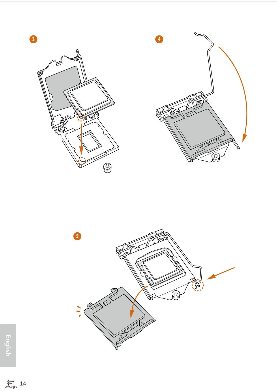
21 Fatal1ty Z97 Professional Series Please save and replace the cover if the processor is removed. he cover must be placed if you wish to return the motherboard for ater service. 15
22 2.2 Installing the CPU Fan and Heatsink 1 2 CPU_FAN 16
23 Fatal1ty Z97 Professional Series 2.3 Installing Memory Modules (DIMM) his motherboard provides four 240-pin DDR3 (Double Data Rate 3) DIMM slots, and supports Dual Channel Memory Technology. 1. For dual channel coniguration, you always need to install identical (the same brand, speed, size and chip-type) DDR3 DIMM pairs. 2. It is unable to activate Dual Channel Memory Technology with only one or three memory module installed. 3. It is not allowed to install a DDR or DDR2 memory module into a DDR3 slot; otherwise, this motherboard and DIMM may be damaged. Dual Channel Memory Coniguration Priority DDR3_A1 DDR3_A2 DDR3_B1 DDR3_B2 1 Populated Populated 2 Populated Populated 3 Populated Populated Populated Populated he DIMM only its in one correct orientation. It will cause permanent damage to the motherboard and the DIMM if you force the DIMM into the slot at incorrect orientation. 17
24
25 Fatal1ty Z97 Professional Series 2.4 Expansion Slots (PCI Express Slots) here are 6 PCI Express slots and 1 mini-pci Express slot on the motherboard. Before installing an expansion card, please make sure that the power supply is switched of or the power cord is unplugged. Please read the documentation of the expansion card and make necessary hardware settings for the card before you start the installation. PCIe slots: PCIE1 (PCIe 2.0 x16 slot) is used for PCI Express x4 lane width graphics cards PCIE2 (PCIe 3.0 x16 slot) is used for PCI Express x16 lane width graphics cards. PCIE3 (PCIe 2.0 x1 slot) is used for PCI Express x1 lane width cards. PCIE4 (PCIe 3.0 x16 slot) is used for PCI Express x8 lane width graphics cards. PCIE5 (PCIe 2.0 x1 slot) is used for PCI Express x1 lane width cards. PCIE6 (PCIe 3.0 x16 slot) is used for PCI Express x4 lane width graphics cards. mini-pcie slot: MINI_PCIE1 (mini-pcie slot) is used for WiFi module. PCIe Slot Conigurations PCIE2 PCIE4 PCIE6 Single Graphics Card x16 N/A N/A Two Graphics Cards in CrossFireX TM or SLI TM Mode x8 x8 N/A hree Graphics Cards in 3-Way CrossFireX TM Mode x8 x4 x4 For a better thermal environment, please connect a chassis fan to the motherboard s chassis fan connector (CHA_FAN1, CHA_FAN2 or CHA_FAN3) when using multiple graphics cards. 19
26 2.5 Jumpers Setup he illustration shows how jumpers are setup. When the jumper cap is placed on the pins, the jumper is Short. If no jumper cap is placed on the pins, the jumper is Open. he illustration shows a 3-pin jumper whose pin1 and pin2 are Short when a jumper cap is placed on these 2 pins. Clear CMOS Jumper (CLRCMOS1) (see p.12, No. 28) Default Clear CMOS CLRCMOS1 allows you to clear the data in CMOS. To clear and reset the system parameters to default setup, please turn of the computer and unplug the power cord from the power supply. Ater waiting for 15 seconds, use a jumper cap to short pin2 and pin3 on CLRCMOS1 for 5 seconds. However, please do not clear the CMOS right ater you update the BIOS. If you need to clear the CMOS when you just inish updating the BIOS, you must boot up the system irst, and then shut it down before you do the clear-cmos action. Please be noted that the password, date, time, and user default proile will be cleared only if the CMOS battery is removed. he Clear CMOS Switch has the same function as the Clear CMOS jumper. 20
27 Fatal1ty Z97 Professional Series 2.6 Onboard Headers and Connectors Onboard headers and connectors are NOT jumpers. Do NOT place jumper caps over these headers and connectors. Placing jumper caps over the headers and connectors will cause permanent damage to the motherboard. System Panel Header (9-pin PANEL1) (see p.12, No. 29) PLED+ PLED- PWRBTN# GND 1 GND RESET# GND HDLED- HDLED+ Connect the power switch, reset switch and system status indicator on the chassis to this header according to the pin assignments below. Note the positive and negative pins before connecting the cables. PWRBTN (Power Switch): Connect to the power switch on the chassis front panel. You may conigure the way to turn of your system using the power switch. RESET (Reset Switch): Connect to the reset switch on the chassis front panel. Press the reset switch to restart the computer if the computer freezes and fails to perform a normal restart. PLED (System Power LED): Connect to the power status indicator on the chassis front panel. he LED is on when the system is operating. he LED keeps blinking when the system is in S1/S3 sleep state. he LED is of when the system is in S4 sleep state or powered of (S5). HDLED (Hard Drive Activity LED): Connect to the hard drive activity LED on the chassis front panel. he LED is on when the hard drive is reading or writing data. he front panel design may difer by chassis. A front panel module mainly consists of power switch, reset switch, power LED, hard drive activity LED, speaker and etc. When connecting your chassis front panel module to this header, make sure the wire assignments and the pin assignments are matched correctly. 21
28 Power LED Header (3-pin PLED1) (see p.12, No. 30) 1 PLED- PLED+ PLED+ Please connect the chassis power LED to this header to indicate the system s power status. Serial ATA3 Connectors (SATA3_0: see p.12, No. 13) (SATA3_1: see p.12, No. 15) (SATA3_2: see p.12, No. 17) (SATA3_3: see p.12, No. 14) (SATA3_4: see p.12, No. 16) (SATA3_5: see p.12, No. 18) (SATA3_A1: see p.12, No. 11) (SATA3_A2: see p.12, No. 12) SATA3_2 SATA3_1 SATA3_0 SATA3_A1 SATA3_5 SATA3_4 SATA3_3 SATA3_A2 hese eight SATA3 connectors support SATA data cables for internal storage devices with up to 6.0 Gb/s data transfer rate. If the esata port on the rear I/O has been connected, the internal SATA3_A2 will not function. he SATA3_1 and SATA3_2 are shared with the SATA Express connector (SATAE_0). he SATA3_4, SATA3_5 are shared with the SATA Express connector (SATAE_1). To minimize the boot time, use Intel Z97 SATA ports (SATA3_0) for your bootable devices. Serial ATA Express Connectors (SATAE_0: see p.12, No. 19) (SATAE_1: see p.12, No. 20) SATA3_1 SATA3_2 SATAE_0 SATA3_4 SATA3_5 SATAE_1 Please connect either SATA or PCIe storage devices to this connector. he lower SATA Express connector (the combination of SATAE_1, SATA3_5, and SATA3_4) is shared with the M.2_ SSD (NGFF) Socket 3. 22
29 Fatal1ty Z97 Professional Series USB 2.0 Headers (9-pin USB4_5) (see p.12, No. 26) (9-pin USB6_7) (see p.12, No. 25) USB_PWR P- P+ GND DUMMY 1 GND P+ P- USB_PWR here are two headers on this motherboard. Each USB 2.0 header can support two ports. USB 3.0 Headers (19-pin USB3_4_5) (see p.12, No. 8) (19-pin USB3_6_7) (see p.12, No. 9) IntA_PB_SSRX- Vbus IntA_PA_SSRX- IntA_PA_SSRX+ GND IntA_PA_SSTX- IntA_PA_SSTX+ GND IntA_PA_D- IntA_PA_D+ 1 Vbus IntA_PB_SSTX- IntA_PB_SSRX+ GND IntA_PB_D- IntA_PB_SSTX+ GND IntA_PB_D+ Dummy Besides four USB 3.0 ports on the I/O panel, there are two headers on this motherboard. Each USB 3.0 header can support two ports. Front Panel Audio Header (9-pin HD_AUDIO1) (see p.12, No. 33) 1 GND PRESENCE# MIC_RET OUT_RET O U T 2 _ L J _ S E N S E OUT2_R MIC2_R MIC2_L his header is for connecting audio devices to the front audio panel. Chassis Speaker Header (4-pin SPEAKER1) (see p.12, No. 27) DUMMY SPEAKER 1 +5V DUMMY Please connect the chassis speaker to this header. 1. High Deinition Audio supports Jack Sensing, but the panel wire on the chassis must support HDA to function correctly. Please follow the instructions in our manual and chassis manual to install your system. 2. If you use an AC 97 audio panel, please install it to the front panel audio header by the steps below: A. Connect Mic_IN (MIC) to MIC2_L. B. Connect Audio_R (RIN) to OUT2_R and Audio_L (LIN) to OUT2_L. C. Connect Ground (GND) to Ground (GND). D. MIC_RET and OUT_RET are for the HD audio panel only. You don t need to connect them for the AC 97 audio panel. E. To activate the front mic, go to the FrontMic Tab in the Realtek Control panel and adjust Recording Volume. 23
30 Chassis and Power Fan Connectors (4-pin CHA_FAN1) (see p.12, No. 24) GND +12V CHA_FAN_SPEED FAN_SPEED_CONTROL Please connect fan cables to the fan connectors and match the black wire to the ground pin. (3-pin CHA_FAN2) (see p.12, No. 36) GND FAN_VOLTAGE CHA_FAN_SPEED (3-pin CHA_FAN3) (see p.12, No. 37) FAN_SPEED FAN_VOLTAGE GND (3-pin PWR_FAN1) (see p.12, No. 6) CPU Fan Connectors (4-pin CPU_FAN1) (see p.12, No. 2) (3-pin CPU_FAN2) (see p.12, No. 5) FAN_SPEED_CONTROL FAN_SPEED +12V GND GND FAN_VOLTAGE CPU_FAN_SPEED his motherboard provides a 4-Pin CPU fan (Quiet Fan) connector. If you plan to connect a 3-Pin CPU fan, please connect it to Pin 1-3. ATX Power Connector (24-pin ATXPWR1) (see p.12, No. 7) his motherboard provides a 24-pin ATX power connector. To use a 20-pin ATX power supply, please plug it along Pin 1 and Pin 13. ATX 12V Power Connector (8-pin ATX12V1) (see p.12, No. 1) his motherboard provides an 8-pin ATX 12V power connector. To use a 4-pin ATX power supply, please plug it along Pin 1 and Pin 5. 24
31 F_CLKRUN# SERIRQ# S_PWRDWN# GND LAD1_L LAD2_L SMB_DATA_MAIN SMB_CLK_MAIN GND GND +3VSB LAD0_L +3V LAD3_L TPM_RST# LFRAME#_L CK_33M_TPM Fatal1ty Z97 Professional Series PCIe Power Connector (4-pin PCIE_PWR1) (see p.12, No. 34) Please connect a 4 pin molex power cable to this connector when more than three graphics cards are installed. HDD Saver Connector (4-pin SATA_PWR_1) (see p.12, No. 10) 1 Please connect the HDD Saver Cable to this connector to manage the power state of HDD. hunderbolt AIC Connector (5-pin TB1) (see p.12, No. 35) Please connect a hunderbolt add-in card (AIC) to this connector via the GPIO cable. Serial Port Header (9-pin COM1) (see p.12, No. 32) 1 RRXD1 DDTR#1 DDSR#1 CCTS#1 RRI#1 RRTS#1 GND TTXD1 DDCD#1 his COM1 header supports a serial port module. TPM Header (17-pin TPMS1) (see p.12, No. 31) 1 his connector supports Trusted Platform Module (TPM) system, which can securely store keys, digital certiicates, passwords, and data. A TPM system also helps enhance network security, protects digital identities, and ensures platform integrity. 25
32 2.7 Smart Switches he motherboard has four smart switches: Power Switch, Reset Switch, Clear CMOS Switch and one BIOS Selection Switch, allowing users to quickly turn on/of the system, reset the system, clear the CMOS values or boot from diferent BIOS. Power Switch (PWRBTN) (see p.12, No. 22) Power Power Switch allows users to quickly turn on/of the system. Reset Switch (RSTBTN) (see p.12, No. 23) Reset Reset Switch allows users to quickly reset the system. Clear CMOS Switch (CLRCBTN) (see p.15, No. 17) Clear CMOS Switch allows users to quickly clear the CMOS values. his function is workable only when you power of your computer and unplug the power supply. BIOS Selection Switch (BIOS_SEL1) (see p.12 No. 21) A B BIOS Selection Switch allows the system to boot from either BIOS A or BIOS B. his motherboard has two BIOS chips, a primary BIOS (BIOS_A) and a backup BIOS (BIOS_ B), which enhances the safety and stability of your system. Normally, the system will work on the primary BIOS. However, if the primary BIOS is corrupted or damaged, just lip the BIOS Selection Switch to B, then the backup BIOS will take over on the next system boot. Ater that, use Secure Backup UEFI in the UEFI Setup Utility to duplicate a working copy of the BIOS iles to the primary BIOS to ensure normal system operation. For safety issues, users are not able to update the backup BIOS manually. Users may refer to the BIOS LEDs (BIOS_A_LED or BIOS_B_LED) to identify which BIOS is currently activated. 26
Copyright Notice: Disclaimer: CALIFORNIA, USA ONLY. Version 1.0 Published May 2014 Copyright 2014 ASRock INC. All rights reserved.
 User Manual Version 1.0 Published May 2014 Copyright 2014 ASRock INC. All rights reserved. Copyright Notice: No part of this documentation may be reproduced, transcribed, transmitted, or translated in
Copyright Notice: Disclaimer: CALIFORNIA, USA ONLY. Version 1.0 Published May 2014 Copyright 2014 ASRock INC. All rights reserved.
 Z97 Extreme9 Z97 Extreme9 Version 1.0 Published May 2014 Copyright 2014 ASRock INC. All rights reserved. Copyright Notice: No part of this documentation may be reproduced, transcribed, transmitted, or
Copyright Notice: Disclaimer: CALIFORNIA, USA ONLY. Version 1.0 Published September 2014 Copyright 2014 ASRock INC. All rights reserved.
 Version 1.0 Published September 2014 Copyright 2014 ASRock INC. All rights reserved. Copyright Notice: No part of this documentation may be reproduced, transcribed, transmitted, or translated in any language,
Copyright Notice: Disclaimer: CALIFORNIA, USA ONLY. Version 1.0 Published July 2015 Copyright 2015 ASRock INC. All rights reserved.
 Version 1.0 Published July 2015 Copyright 2015 ASRock INC. All rights reserved. Copyright Notice: No part of this documentation may be reproduced, transcribed, transmitted, or translated in any language,
Copyright Notice: Disclaimer: CALIFORNIA, USA ONLY. Version 1.0 Published March 2013 Copyright 2013 ASRock INC. All rights reserved.
 User Manual Version 1.0 Published March 2013 Copyright 2013 ASRock INC. All rights reserved. Copyright Notice: No part of this documentation may be reproduced, transcribed, transmitted, or translated in
Copyright Notice: Disclaimer: CALIFORNIA, USA ONLY. Version 1.0 Published April 2014 Copyright 2014 ASRock INC. All rights reserved.
 Version 1.0 Published April 2014 Copyright 2014 ASRock INC. All rights reserved. Copyright Notice: No part of this documentation may be reproduced, transcribed, transmitted, or translated in any language,
Copyright Notice: Disclaimer: CALIFORNIA, USA ONLY. Version 1.2 Published October 2014 Copyright 2014 ASRock INC. All rights reserved.
 Version 1.2 Published October 2014 Copyright 2014 ASRock INC. All rights reserved. Copyright Notice: No part of this documentation may be reproduced, transcribed, transmitted, or translated in any language,
Copyright Notice: Disclaimer: CALIFORNIA, USA ONLY. Version 1.0 Published March 2013 Copyright 2013 ASRock INC. All rights reserved.
 User Manual Version 1.0 Published March 2013 Copyright 2013 ASRock INC. All rights reserved. Copyright Notice: No part of this documentation may be reproduced, transcribed, transmitted, or translated in
Copyright Notice: Disclaimer: CALIFORNIA, USA ONLY. Version 1.0 Published May 2013 Copyright 2013 ASRock INC. All rights reserved.
 Version 1.0 Published May 2013 Copyright 2013 ASRock INC. All rights reserved. Copyright Notice: No part of this documentation may be reproduced, transcribed, transmitted, or translated in any language,
Copyright Notice: Disclaimer: CALIFORNIA, USA ONLY. Version 1.1 Published May 2015 Copyright 2015 ASRock INC. All rights reserved.
 N3700-ITX N3150-ITX N3700-ITX N3150-ITX Version 1.1 Published May 2015 Copyright 2015 ASRock INC. All rights reserved. Copyright Notice: No part of this documentation may be reproduced, transcribed, transmitted,
Copyright Notice: Disclaimer: CALIFORNIA, USA ONLY. Version 1.0 Published July 2014 Copyright 2014 ASRock INC. All rights reserved.
 FM2A78M-HD+ R2.0 FM2A78M-HD+ R2.0 Version 1.0 Published July 2014 Copyright 2014 ASRock INC. All rights reserved. Copyright Notice: No part of this documentation may be reproduced, transcribed, transmitted,
X79 Extreme4. User Manual. Version 1.1 Published July 2013 Copyright 2013 ASRock INC. All rights reserved.
 X79 Extreme4 User Manual Version 1.1 Published July 2013 Copyright 2013 ASRock INC. All rights reserved. 1 Copyright Notice: No part of this manual may be reproduced, transcribed, transmitted, or translated
Copyright Notice: Disclaimer: CALIFORNIA, USA ONLY. Version 1.0 Published August 2014 Copyright 2014 ASRock INC. All rights reserved.
 H97 Anniversary H97 Anniversary Version 1.0 Published August 2014 Copyright 2014 ASRock INC. All rights reserved. Copyright Notice: No part of this documentation may be reproduced, transcribed, transmitted,
Copyright Notice: Disclaimer: CALIFORNIA, USA ONLY. Version 1.1 Published November 2014 Copyright 2014 ASRock INC. All rights reserved.
 B85 Anniversary B85 Anniversary Version 1.1 Published November 2014 Copyright 2014 ASRock INC. All rights reserved. Copyright Notice: No part of this documentation may be reproduced, transcribed, transmitted,
Copyright Notice: Disclaimer:
 User Manual Version 1.0 Published August 2013 Copyright 2013 ASRock INC. All rights reserved. Copyright Notice: No part of this documentation may be reproduced, transcribed, transmitted, or translated
Z77 WS. User Manual. Version 1.0 Published August 2012 Copyright 2012 ASRock INC. All rights reserved.
 Z77 WS User Manual Version 1.0 Published August 2012 Copyright 2012 ASRock INC. All rights reserved. 1 Copyright Notice: No part of this manual may be reproduced, transcribed, transmitted, or translated
Z97-PRO GAMER Especificaciones
 Z97-PRO GAMER Especificaciones CPU Intel Socket 1150 for the 5 th /New 4 th /4 th Generation Core i7/core i5/core i3/pentium /Celeron Processors Supports Intel 22 nm CPU Supports Intel Turbo Boost Technology
Copyright Notice: Disclaimer: CALIFORNIA, USA ONLY. Version 1.1 Published October 2014 Copyright 2014 ASRock INC. All rights reserved.
 B85M Pro3 B85M Pro3 Version 1.1 Published October 2014 Copyright 2014 ASRock INC. All rights reserved. Copyright Notice: No part of this documentation may be reproduced, transcribed, transmitted, or translated
EVGA Z97 Classified Specs and Initial Installation (Part 1)
") User Guide EVGA Z97 Classified Specs and Initial Installation (Part 1) - 1 - Table of Contents Before you Begin 3 Parts Not in the kit.4 Intentions of the kit 4 Motherboard Specifications 5 Unpacking and
User Guide EVGA Z97 Classified Specs and Initial Installation (Part 1) - 1 - Table of Contents Before you Begin 3 Parts Not in the kit.4 Intentions of the kit 4 Motherboard Specifications 5 Unpacking and
P75 Pro3. User Manual. Version 1.0 Published August 2012 Copyright 2012 ASRock INC. All rights reserved.
 P75 Pro3 User Manual Version 1.0 Published August 2012 Copyright 2012 ASRock INC. All rights reserved. 1 Copyright Notice: No part of this manual may be reproduced, transcribed, transmitted, or translated
EVGA X99 Classified Specs and Initial Installation (Part 1)
") User Guide EVGA X99 Classified Specs and Initial Installation (Part 1) - 1 - Table of Contents Before you Begin 3 Parts Not in the kit.4 Intentions of the kit 4 Motherboard Specifications 5 Unpacking and
User Guide EVGA X99 Classified Specs and Initial Installation (Part 1) - 1 - Table of Contents Before you Begin 3 Parts Not in the kit.4 Intentions of the kit 4 Motherboard Specifications 5 Unpacking and
Copyright Notice: Disclaimer: CALIFORNIA, USA ONLY. Version 1.1 Published November 2014 Copyright 2014 ASRock INC. All rights reserved.
 Z97M-ITX/ac Z97M Pro4 Version 1.1 Published November 2014 Copyright 2014 ASRock INC. All rights reserved. Copyright Notice: No part of this documentation may be reproduced, transcribed, transmitted, or
H61M-VG3 / H61M-VS3. User Manual. Version 1.0 Published October 2012 Copyright 2012 ASRock INC. All rights reserved.
 H61M-VG3 / H61M-VS3 User Manual Version 1.0 Published October 2012 Copyright 2012 ASRock INC. All rights reserved. 1 Copyright Notice: No part of this manual may be reproduced, transcribed, transmitted,
IPN73-BA Motherboard layout reference Contents
 IPN73-BA Motherboard layout reference Contents Specifications summary Motherboard layout Rear panel connectors Function selectors Status indicators Internal connectors February 2008 Specifications summary
ALiveNF5-eSATA2+ User Manual. Version 1.0 Published January 2007 Copyright 2007 ASRock INC. All rights reserved.
 ALiveNF5-eSATA2+ User Manual Version 1.0 Published January 2007 Copyright 2007 ASRock INC. All rights reserved. 1 Copyright Notice: No part of this manual may be reproduced, transcribed, transmitted, or
Copyright Notice: Disclaimer: CALIFORNIA, USA ONLY. Version 1.0 Published June 2015 Copyright 2015 ASRock INC. All rights reserved.
 Version 1.0 Published June 2015 Copyright 2015 ASRock INC. All rights reserved. Copyright Notice: No part of this documentation may be reproduced, transcribed, transmitted, or translated in any language,
SABERTOOTH Z97 MARK 2
 SABERTOOTH Z97 MARK 2 Intel Socket 1150 for the 5 th /New 4 th /4 th Generation Core i7/core i5/core i3/pentium /Celeron Processors Supports Intel 22 nm CPU Supports Intel Turbo Boost Technology 2.0 *
IPMIP-GS Series Motherboard layout reference
 IPMIP-GS Series Motherboard layout reference Contents Specifications summary Motherboard layout Rear panel s Internal s This manual is meant as a general reference guide. Refer to the product itself for
970 Pro3 R2.0. User Manual. Version 1.0 Published September 2012 Copyright 2012 ASRock INC. All rights reserved.
 970 Pro3 R2.0 User Manual Version 1.0 Published September 2012 Copyright 2012 ASRock INC. All rights reserved. 1 Copyright Notice: No part of this manual may be reproduced, transcribed, transmitted, or
B75 Pro3-M. User Manual. Version 1.1 Published June 2013 Copyright 2013 ASRock INC. All rights reserved.
 B75 Pro3-M User Manual Version 1.1 Published June 2013 Copyright 2013 ASRock INC. All rights reserved. 1 Copyright Notice: No part of this manual may be reproduced, transcribed, transmitted, or translated
FM2A85X Extreme4. User Manual. Version 1.0 Published October 2012 Copyright 2012 ASRock INC. All rights reserved.
 FM2A85X Extreme4 User Manual Version 1.0 Published October 2012 Copyright 2012 ASRock INC. All rights reserved. 1 Copyright Notice: No part of this manual may be reproduced, transcribed, transmitted, or
PV530-ITX. www.asrock.com. Product Brief. Detail Specification. VIA PV530 CPU + VX900 Chipset
 Detail Specification Platform - Mini-ITX Form Factor: 6.7-in x 6.7-in, 17.0 cm x 17.0 cm - Solid Capacitor for CPU power CPU Chipset Memory - VIA PV530 Processor (1.8 GHz) - Supports FSB800 MHz - Supports
A75M-ITX. User Manual. Version 1.0 Published July 2011 Copyright 2011 ASRock INC. All rights reserved.
 A75M-ITX User Manual Version 1.0 Published July 2011 Copyright 2011 ASRock INC. All rights reserved. 1 Copyright Notice: No part of this manual may be reproduced, transcribed, transmitted, or translated
Copyright Notice: Disclaimer: CALIFORNIA, USA ONLY. Version 1.0 Published September 2013 Copyright 2013 ASRock INC. All rights reserved.
 User Manual Version 1.0 Published September 2013 Copyright 2013 ASRock INC. All rights reserved. Copyright Notice: No part of this documentation may be reproduced, transcribed, transmitted, or translated
Copyright Notice: Disclaimer: CALIFORNIA, USA ONLY. Version 1.0 Published March 2013 Copyright 2013 ASRock INC. All rights reserved.
 User Manual Version 1.0 Published March 2013 Copyright 2013 ASRock INC. All rights reserved. Copyright Notice: No part of this documentation may be reproduced, transcribed, transmitted, or translated in
H97M-E/CSM. Chipset. Memory. Graphic. Expansion Slots. Storage
 H97M-E/CSM Intel Socket 1150 for the 5 th /New 4 th /4 th Generation Core i7/core i5/core i3/pentium /Celeron Processors Supports Intel 22 nm CPU Supports Intel Turbo Boost Technology 2.0 * The Intel Turbo
SABERTOOTH Z97 MARK 1
 SABERTOOTH Z97 MARK 1 Intel Socket 1150 for the 5 th /New 4 th /4 th Generation Core i7/core i5/core i3/pentium /Celeron Processors Supports Intel 22 nm CPU Supports Intel Turbo Boost Technology 2.0 *
B75M-ITX. User Manual. Version 1.1 Published June 2013 Copyright 2013 ASRock INC. All rights reserved.
 B75M-ITX User Manual Version 1.1 Published June 2013 Copyright 2013 ASRock INC. All rights reserved. 1 Copyright Notice: No part of this manual may be reproduced, transcribed, transmitted, or translated
P43R1600Twins-WiFi / P43R1600Twins-110dB / P43R1600Twins
 P43R1600Twins-WiFi / P43R1600Twins-110dB / P43R1600Twins User Manual Version 1.0 Published May 2008 Copyright 2008 ASRock INC. All rights reserved. 1 Copyright Notice: No part of this manual may be reproduced,
Getting Started. Chapter 1
 Chapter 1 Getting Started Thank you for choosing the 7728 v2.x Series Micro-ATX mainboard. The 7728 v2.x Series mainboards are based on Intel H61 chipsets for optimal system efficiency. Designed to fit
H77 Pro4-M. User Manual. Version 1.1 Published June 2013 Copyright 2013 ASRock INC. All rights reserved.
 H77 Pro4-M User Manual Version 1.1 Published June 2013 Copyright 2013 ASRock INC. All rights reserved. 1 Copyright Notice: No part of this manual may be reproduced, transcribed, transmitted, or translated
FM2A75M-ITX. User Manual. Version 1.0 Published September 2012 Copyright 2012 ASRock INC. All rights reserved.
 FM2A75M-ITX User Manual Version 1.0 Published September 2012 Copyright 2012 ASRock INC. All rights reserved. 1 Copyright Notice: No part of this manual may be reproduced, transcribed, transmitted, or translated
Copyright Notice: Disclaimer: CALIFORNIA, USA ONLY. Version 1.1 Published October 2014 Copyright 2014 ASRock INC. All rights reserved.
 User Manual Version 1.1 Published October 2014 Copyright 2014 ASRock INC. All rights reserved. Copyright Notice: No part of this documentation may be reproduced, transcribed, transmitted, or translated
Copyright Notice: Disclaimer: CALIFORNIA, USA ONLY. Version 1.0 Published July 2015 Copyright 2015 ASRock INC. All rights reserved.
 Version 1.0 Published July 2015 Copyright 2015 ASRock INC. All rights reserved. Copyright Notice: No part of this documentation may be reproduced, transcribed, transmitted, or translated in any language,
FM2A85X Extreme4-M. User Manual. Version 1.1 Published July 2013 Copyright 2013 ASRock INC. All rights reserved.
 FM2A85X Extreme4-M User Manual Version 1.1 Published July 2013 Copyright 2013 ASRock INC. All rights reserved. 1 Copyright Notice: No part of this manual may be reproduced, transcribed, transmitted, or
Z77 Pro3. User Manual. Version 1.2 Published June 2013 Copyright 2013 ASRock INC. All rights reserved.
 Z77 Pro3 User Manual Version 1.2 Published June 2013 Copyright 2013 ASRock INC. All rights reserved. 1 Copyright Notice: No part of this manual may be reproduced, transcribed, transmitted, or translated
QC5000-ITX/WiFi QC5000-ITX. User Manual
 QC5000-ITX/WiFi QC5000-ITX User Manual Version 1.0 Published March 2014 Copyright 2014 ASRock INC. All rights reserved. Copyright Notice: No part of this documentation may be reproduced, transcribed, transmitted,
Copyright Notice: Disclaimer: CALIFORNIA, USA ONLY. Version 1.0 Published August 2013 Copyright 2013 ASRock INC. All rights reserved.
 User Manual Version 1.0 Published August 2013 Copyright 2013 ASRock INC. All rights reserved. Copyright Notice: No part of this documentation may be reproduced, transcribed, transmitted, or translated
880GMH/U3S3. User Manual. Version 1.0 Published February 2011 Copyright 2011 ASRock INC. All rights reserved.
 880GMH/U3S3 User Manual Version 1.0 Published February 2011 Copyright 2011 ASRock INC. All rights reserved. 1 Copyright Notice: No part of this manual may be reproduced, transcribed, transmitted, or translated
Using GIGABYTE Notebook for the First Time
 Congratulations on your purchase of the GIGABYTE Notebook P7! This Manual will help you to get started with setting up your notebook. For more detailed information, please visit our website at http://www.gigabyte.com.
Copyright Notice: Disclaimer: CALIFORNIA, USA ONLY. Version 1.1 Published October 2014 Copyright 2014 ASRock INC. All rights reserved.
 User Manual Version 1.1 Published October 2014 Copyright 2014 ASRock INC. All rights reserved. Copyright Notice: No part of this documentation may be reproduced, transcribed, transmitted, or translated
Using AORUS Notebook for the First Time
 V2.0 Congratulations on your purchase of the AORUS Notebook! This Manual will help you to get started with setting up your notebook. For more detailed information, please visit our website at http://www.aorus.com.
X58 SuperComputer. User Manual. Version 1.2 Published April 2009 Copyright 2009 ASRock INC. All rights reserved.
 X58 SuperComputer User Manual Version 1.2 Published April 2009 Copyright 2009 ASRock INC. All rights reserved. 1 Copyright Notice: No part of this manual may be reproduced, transcribed, transmitted, or
Copyright Notice: Disclaimer: CALIFORNIA, USA ONLY. Version 1.0 Published May 2014 Copyright 2014 ASRock INC. All rights reserved.
 B85M-DGS B85M DGS Version 1.0 Published May 2014 Copyright 2014 ASRock INC. All rights reserved. Copyright Notice: No part of this documentation may be reproduced, transcribed, transmitted, or translated
Copyright Notice: Disclaimer: CALIFORNIA, USA ONLY. Version 1.0 Published June 2015 Copyright 2015 ASRock INC. All rights reserved.
 Version 1.0 Published June 2015 Copyright 2015 ASRock INC. All rights reserved. Copyright Notice: No part of this documentation may be reproduced, transcribed, transmitted, or translated in any language,
Copyright Notice: Disclaimer: CALIFORNIA, USA ONLY. Version 1.0 Published March 2013 Copyright 2013 ASRock INC. All rights reserved.
 User Manual Version 1.0 Published March 2013 Copyright 2013 ASRock INC. All rights reserved. Copyright Notice: No part of this documentation may be reproduced, transcribed, transmitted, or translated in
H61M-GS / H61M-S. User Manual. Version 1.1 Published May 2012 Copyright 2012 ASRock INC. All rights reserved.
 H61M-GS / H61M-S User Manual Version 1.1 Published May 2012 Copyright 2012 ASRock INC. All rights reserved. 1 Copyright Notice: No part of this manual may be reproduced, transcribed, transmitted, or translated
AP480-S Motherboard layout reference Contents
 AP80-S Motherboard layout reference Contents Specifications summary Motherboard layout Rear panel connectors Function selectors Internal connectors JUL 2008 Specifications summary CPU Chipset Front Side
B75M-DGS. User Manual. Version 1.0 Published July 2012 Copyright 2012 ASRock INC. All rights reserved.
 B75M-DGS User Manual Version 1.0 Published July 2012 Copyright 2012 ASRock INC. All rights reserved. 1 Copyright Notice: No part of this manual may be reproduced, transcribed, transmitted, or translated
760GM-GS3 / 760GM-S3. User Manual. Version 1.0 Published September 2010 Copyright 2010 ASRock INC. All rights reserved.
 760GM-GS3 / 760GM-S3 User Manual Version 1.0 Published September 2010 Copyright 2010 ASRock INC. All rights reserved. 1 Copyright Notice: No part of this manual may be reproduced, transcribed, transmitted,
P67 Pro3. www.asrock.com. Detail Specification. Product Brief. Intel P67 Chipset
 Detail Specification Platform CPU - ATX Form Factor: 12.0-in x 9.6-in, 30.5 cm x 24.4 cm - All Solid Capacitor design (100% Japan-made high-quality Conductive Polymer Capacitors) - Supports 2 nd Generation
FM2A75M-DGS. User Manual. Version 1.0 Published August 2012 Copyright 2012 ASRock INC. All rights reserved.
 FM2A75M-DGS User Manual Version 1.0 Published August 2012 Copyright 2012 ASRock INC. All rights reserved. 1 Copyright Notice: No part of this manual may be reproduced, transcribed, transmitted, or translated
X48TurboTwins-WiFi / X48TurboTwins
 X48TurboTwins-WiFi / X48TurboTwins User Manual Version 1.1 Published June 2008 Copyright 2008 ASRock INC. All rights reserved. 1 Copyright Notice: No part of this manual may be reproduced, transcribed,
N68-GE3 UCC. User Manual. Version 1.0 Published July 2010 Copyright 2010 ASRock INC. All rights reserved.
 N68-GE3 UCC User Manual Version 1.0 Published July 2010 Copyright 2010 ASRock INC. All rights reserved. 1 Copyright Notice: No part of this manual may be reproduced, transcribed, transmitted, or translated
FM2A85X-ITX. User Manual. Version 1.1 Published July 2013 Copyright 2013 ASRock INC. All rights reserved.
 FM2A85X-ITX User Manual Version 1.1 Published July 2013 Copyright 2013 ASRock INC. All rights reserved. 1 Copyright Notice: No part of this manual may be reproduced, transcribed, transmitted, or translated
AD2550B-ITX. User Manual. Version 1.1 Published June 2013 Copyright 2013 ASRock INC. All rights reserved.
 AD2550B-ITX User Manual Version 1.1 Published June 2013 Copyright 2013 ASRock INC. All rights reserved. 1 Copyright Notice: No part of this manual may be reproduced, transcribed, transmitted, or translated
Copyright Notice: Disclaimer: CALIFORNIA, USA ONLY. Version 1.0 Published October 2013 Copyright 2013 ASRock INC. All rights reserved.
 User Manual Version 1.0 Published October 2013 Copyright 2013 ASRock INC. All rights reserved. Copyright Notice: No part of this documentation may be reproduced, transcribed, transmitted, or translated
Z77 Extreme11. User Manual. Version 1.0 Published September 2012 Copyright 2012 ASRock INC. All rights reserved.
 Z77 Extreme11 User Manual Version 1.0 Published September 2012 Copyright 2012 ASRock INC. All rights reserved. 1 Copyright Notice: No part of this manual may be reproduced, transcribed, transmitted, or
H61DE/S3. User Manual. Version 1.1 Published May 2012 Copyright 2012 ASRock INC. All rights reserved.
 H61DE/S3 User Manual Version 1.1 Published May 2012 Copyright 2012 ASRock INC. All rights reserved. 1 Copyright Notice: No part of this manual may be reproduced, transcribed, transmitted, or translated
880GXH/USB3. User Manual. Version 1.0 Published April 2010 Copyright 2010 ASRock INC. All rights reserved.
 880GXH/USB3 User Manual Version.0 Published April 200 Copyright 200 ASRock INC. All rights reserved. Copyright Notice: No part of this manual may be reproduced, transcribed, transmitted, or translated
A770DE. User Manual. Version 1.0 Published November 2008 Copyright 2008 ASRock INC. All rights reserved.
 A770DE User Manual Version 1.0 Published November 2008 Copyright 2008 ASRock INC. All rights reserved. 1 Copyright Notice: No part of this manual may be reproduced, transcribed, transmitted, or translated
Copyright Notice: Disclaimer: CALIFORNIA, USA ONLY. Version 1.0 Published March 2013 Copyright 2013 ASRock INC. All rights reserved.
 User Manual Version 1.0 Published March 2013 Copyright 2013 ASRock INC. All rights reserved. Copyright Notice: No part of this documentation may be reproduced, transcribed, transmitted, or translated in
USB 2.0 VGA ADAPTER USER MANUAL
 USB 2.0 VGA ADAPTER USER MANUAL CONTENTS INTRODUCTION... 3 FEATURES... 3 SYSTEM REQUIREMENTS... 3 PACKAGE CONTENTS... 3 SUPPORTED COMMON DISPLAY RESOLUTION... 4 TECHNICAL SPECIFICATIONS... 4 INSTALLATION
Z77E-ITX. User Manual. Version 1.1 Published July 2012 Copyright 2012 ASRock INC. All rights reserved.
 Z77E-ITX User Manual Version 1.1 Published July 2012 Copyright 2012 ASRock INC. All rights reserved. 1 Copyright Notice: No part of this manual may be reproduced, transcribed, transmitted, or translated
990FX Extreme4. User Manual. Version 1.2 Published July 2013 Copyright 2013 ASRock INC. All rights reserved.
 990FX Extreme4 User Manual Version 1.2 Published July 2013 Copyright 2013 ASRock INC. All rights reserved. 1 Copyright Notice: No part of this manual may be reproduced, transcribed, transmitted, or translated
AD2550-ITX. User Manual. Version 1.0 Published March 2013 Copyright 2013 ASRock INC. All rights reserved.
 AD2550-ITX User Manual Version 1.0 Published March 2013 Copyright 2013 ASRock INC. All rights reserved. 1 Copyright Notice: No part of this manual may be reproduced, transcribed, transmitted, or translated
N61P-GS / N61P-S. User Manual. Version 1.0 Published September 2008 Copyright 2008 ASRock INC. All rights reserved.
 N61P-GS / N61P-S User Manual Version 1.0 Published September 2008 Copyright 2008 ASRock INC. All rights reserved. 1 Copyright Notice: No part of this manual may be reproduced, transcribed, transmitted,
N68PV-GS. User Manual. Version 1.0 Published September 2008 Copyright 2008 ASRock INC. All rights reserved.
 N68PV-GS User Manual Version 1.0 Published September 2008 Copyright 2008 ASRock INC. All rights reserved. 1 Copyright Notice: No part of this manual may be reproduced, transcribed, transmitted, or translated
Using GIGABYTE Notebook for the First Time
 Congratulations on your purchase of the GIGABYTE Notebook! This Manual will help you to get started with setting up your notebook. For more detailed information, please visit our website at http://www.gigabyte.com.
Using GIGABYTE Notebook for the First Time
 P34 V6.0 Congratulations on your purchase of the GIGABYTE Notebook. This manual will help you to get started with setting up your notebook. The final product configuration depends on the model at the point
Getting Started. Chapter 1
 Chapter 1 Getting Started Thank you for choosing the 7667 v2.2 Series (MS-7667) Micro-ATX mainboard. The series mainboards are based on Intel P67 chipsets for optimal system efficiency. Designed to fit
Executive Series. Intel Desktop Board DB75EN Executive Series MicroATX Form Factor
 Intel Desktop Board DB75EN MicroATX Form Factor product brief Built for Business: Intel Desktop Board DB75EN maximizes employee productivity, PC performance, and data security with Intel Small Business
Z68 Extreme7 Gen3. User Manual. Version 1.0 Published July 2011 Copyright 2011 ASRock INC. All rights reserved.
 Z68 Extreme7 Gen3 User Manual Version 1.0 Published July 2011 Copyright 2011 ASRock INC. All rights reserved. 1 Copyright Notice: No part of this manual may be reproduced, transcribed, transmitted, or
Using GIGABYTE Notebook for the First Time
 P55 V3.0 Congratulations on your purchase of the GIGABYTE Notebook. This manual will help you to get started with setting up your notebook. The final product configuration depends on the model at the point
ZOTAC ZBOX User s Manual
 ZOTAC ZBOX User s Manual No part of this manual, including the products and software described in it, may be reproduced, transmitted, transcribed, stored in a retrieval system, or translated into any language
Using GIGABYTE Notebook for the First Time
 Congratulations on your purchase of the GIGABYTE Notebook. This manual will help you to get started with setting up your notebook. The final product configuration depends on the model at the point of your
ZOTAC ZBOX nano User s Manual
 ZOTAC ZBOX nano User s Manual No part of this manual, including the products and software described in it, may be reproduced, transmitted, transcribed, stored in a retrieval system, or translated into
Ultra Thin Client TC-401 TC-402. Users s Guide
 Ultra Thin Client TC-401 TC-402 Users s Guide CONTENT 1. OVERVIEW... 3 1.1 HARDWARE SPECIFICATION... 3 1.2 SOFTWARE OVERVIEW... 4 1.3 HARDWARE OVERVIEW...5 1.4 NETWORK CONNECTION... 7 2. INSTALLING THE
970 Pro3. User Manual. Version 1.0 Published April 2012 Copyright 2012 ASRock INC. All rights reserved.
 970 Pro3 User Manual Version 1.0 Published April 2012 Copyright 2012 ASRock INC. All rights reserved. 1 Copyright Notice: No part of this manual may be reproduced, transcribed, transmitted, or translated
ENLTV-FM3. PCI TV Tuner Adapter with FM Radio. User s Guide
 ENLTV-FM3 PCI TV Tuner Adapter with FM Radio User s Guide User s Notice No part of this manual, including the products and software described in it, may be reproduced, transmitted, transcribed, stored
BIOS Update Release Notes
 BIOS Update Release Notes PRODUCTS: DH61BE, DH61CR, DH61DL, DH61WW, DH61SA, DH61ZE (Standard BIOS) BIOS Version 0120 - BEH6110H.86A.0120.2013.1112.1412 Date: November 12, 2013 ME Firmware: Ignition SKU
E350M1. User Manual. Version 1.1 Published June 2011 Copyright 2011 ASRock INC. All rights reserved.
 E350M1 User Manual Version 1.1 Published June 2011 Copyright 2011 ASRock INC. All rights reserved. 1 Copyright Notice: No part of this manual may be reproduced, transcribed, transmitted, or translated
E350M1/USB3. User Manual. Version 1.1 Published June 2011 Copyright 2011 ASRock INC. All rights reserved.
 E350M1/USB3 User Manual Version 1.1 Published June 2011 Copyright 2011 ASRock INC. All rights reserved. 1 Copyright Notice: No part of this manual may be reproduced, transcribed, transmitted, or translated
Supports NVIDIA Quad-GPU SLI Technology * Supports AMD Quad-GPU CrossFireX Technology Supports AMD 3-Way CrossFireX Technology
 Pagina 1 di 5 Z87-DELUXE CPU th Intel Socket 1150 for 4 Generation Core i7/core i5/core i3/pentium /Celeron Processors Supports Intel 22 nm CPU Supports Intel Turbo Boost Technology 2.0 * The Intel Turbo
ZOTAC ZBOX User s Manual
 ZOTAC ZBOX User s Manual No part of this manual, including the products and software described in it, may be reproduced, transmitted, transcribed, stored in a retrieval system, or translated into any language
Getting Started. Version 3.1 Last updated 2014/3/10. Orbweb ME: Getting Started
 Information in this document is subject to change without notice. Companies, names, and data used in examples herein are fictitious unless otherwise noted. No part of this document may be reproduced or
FM2A55M-DGS. User Manual. Version 1.0 Published August 2012 Copyright 2012 ASRock INC. All rights reserved.
 FM2A55M-DGS User Manual Version 1.0 Published August 2012 Copyright 2012 ASRock INC. All rights reserved. 1 Copyright Notice: No part of this manual may be reproduced, transcribed, transmitted, or translated
ALiveNF6G-DVI ALiveNF6G-VSTA
 ALiveNF6G-DVI ALiveNF6G-VSTA User Manual Version.3 Published December 2006 Copyright 2006 ASRock INC. All rights reserved. Copyright Notice: No part of this manual may be reproduced, transcribed, transmitted,
890FX Deluxe5. User Manual. Version 1.0 Published January 2011 Copyright 2011 ASRock INC. All rights reserved.
 890FX Deluxe5 User Manual Version 1.0 Published January 2011 Copyright 2011 ASRock INC. All rights reserved. 1 Copyright Notice: No part of this manual may be reproduced, transcribed, transmitted, or translated
A785GXH/128M. User Manual. Version 1.0 Published August 2009 Copyright 2009 ASRock INC. All rights reserved.
 A785GXH/128M User Manual Version 1.0 Published August 2009 Copyright 2009 ASRock INC. All rights reserved. 1 Copyright Notice: No part of this manual may be reproduced, transcribed, transmitted, or translated