ITU Training on Conformance and Interoperability for ARB Region CERT, 2-6 April 2013, EMC standards. Presented by: Karim Loukil & Kaïs Siala
|
|
|
- Aubrey Mason
- 7 years ago
- Views:
Transcription

1 ITU Training on Conformance and Interoperability for ARB Region CERT, 2-6 April 2013, EMC standards Presented by: Karim Loukil & Kaïs Siala 1

2 Types of EMC measures Emission Immunity Radiated Conducted
3 Immunity tests The purpose of immunity tests is to subject a product to a controlled stress that represents the likely range which is mostly dedicated by practical aspects and experience of real-world problems. 3
4 Immunity tests 1 transient phenomena 4
5 Performance Criteria for Immunity Tests Results of immunity tests are classified into four categories: Performance Criteria A Performance within specification limits Performance Criteria B Temporary degradation which is selfrecoverable Performance Criteria C Temporary degradation which requires operator intervention Performance Criteria D Loss of function which is not recoverable 5
6 ESD IEC

7 Electrostatic Discharge ESD IEC
8 Electrostatic discharge (IEC ) Test purpose Evaluate the performance of a device submitted to human electric discharge Needed instruments: ESD generator Ground plane (horizontal and vertical) Isolant surface 2 x 470 kω resistances 8
9 ESD generator 9
10 ESD Test setup EUT VCP 0.1 m 470 kohm 470 kohm 470 kohm 470 kohm Conducting surface Dielectrical material Isolating surface
11 ESD Waveform 11
12 Test levels 12
13 Performance Criteria for Immunity Tests Results of immunity tests are classified into four categories: Performance Criteria A Performance within specification limits Performance Criteria B Temporary degradation which is selfrecoverable Performance Criteria C Temporary degradation which requires operator intervention Performance Criteria D Loss of function which is not recoverable 13
14 Standards calls 14
15 Application of discharge: Discharge Application Direct: on the surface of the device under test Indirect: in the coupling planes Types of discharges: In contact: the conductive surface (head pointed gun) In air: on insolating surfaces (gun head rounded) one discharge each 3 sec 10 discharges + and - by point of application 4 test levels For high levels we must pass by intermediate levels 15

16 Choice of discharge points 16
17 The discharge return cable of the ESD generator shall be connected to the ground reference plane. The total length of this cable is 2 m. 17
18 Fundamental Principals In the case of air discharge testing, the climatic conditions shall be within the following ranges: ambient temperature: 15 C to 35 C; relative humidity: 30 % to 60 %; atmospheric pressure: 86 kpa (860 mbar) to 106 kpa (1 060 mbar). 18
19 Execution of the test The testing shall be performed by direct and indirect application of discharges to the EUT according to a test plan. This should include: representative operating conditions of the EUT; whether the EUT should be tested as table-top or floor-standing; the points at which discharges are to be applied; at each point, whether contact or air discharges are to be applied; the test level to be applied; the number of discharges to be applied at each point for compliance testing; 19
20 Contact/air discharge In the case of contact discharges, the tip of the discharge electrode shall touch the EUT, before the discharge switch is operated. In the case of air discharges, the round discharge tip of the discharge electrode shall be approached as fast as possible (without causing mechanical damage) to touch the EUT. Link to the standard IEC
21 EFT IEC
22 The EFT phenomenum When a circuit is switched off, the current flowing through the switch is interrupted more or less instantaneously. At the moment of switching there is an infinite di/dt. All circuits have some stray inductance associated with the wiring; some types of load, such as motors or solenoids, have considerably more inductance in the load itself. The voltage developed across an inductance L by a changing current i is : V = -L di/dt 22
23 The EFT phenomenum 23
24 Electrical fast transients IEC Purpose of test: Immunity test when subjected to transient disturbances like switching transients. Materials needed: EFT generator Coupling & decoupling device (internal or external) Capacitive coupling clamp for telecom line coupling Capacity of 33 nf for direct injection Ground plane 24
25 Electric Fast Transients EFT Burst EN Coupling/decoupling Wave form generator Network EUT Burst generator With integrated CDN 0.1 m Ground plane Dielectric material 0.1 m 25
26 Test levels 26
27 Performance Criteria for Immunity Tests Results of immunity tests are classified into four categories: Performance Criteria A Performance within specification limits Performance Criteria B Temporary degradation which is selfrecoverable Performance Criteria C Temporary degradation which requires operator intervention Performance Criteria D Loss of function which is not recoverable 27
28 Standards calls 28

29 EFT wave form 29
30 EFT Application On each conductor For at least 1 min polarity + And Test levels and intermediate levels 30
31 Test setup Table-top equipment : EUT located 0,1 m above the ground plane. The test generator and CDN placed directly on, and connected to, the ground plane. All cables connected to the EUT shall be placed on the insulation support 0,1 m above the ground reference plane. 31
32 Test setup Either a direct coupling network or a capacitive clamp shall be used for the application of the test voltages. Decoupling networks shall be used to protect auxiliary equipment and public networks. 32
33 Test procedure The test procedure includes: the verification of the laboratory reference conditions; the preliminary verification of the correct operation of the equipment; the execution of the test; the evaluation of the test results. 33
34 Test setup 34
35 Capacitive coupling clamp Link to the standard IEC
36 Surge IEC

37 The surge phenomenum 37
38 Surge effects Surges impinging on electronic equipment may cause hardware damage and complete failure, or in lesser cases, operational upset. Below some level dependent on equipment design, no effect is observed. Above this level, a surge may cause the operation of the equipment to change state 38
39 Surge tests (IEC ) Purpose of test: Evaluation the immunity of a device across shock waves caused by transient voltages induced by the residual or lightning impulse Materials needed: Surge wave generator (1.2 / 50 microseconds), Decoupling/coupling network (internal or external) Ground plane 39
40 Surge immunity IEC Wave form generator Coupling/decoupking Network EUT Surge generator With integrated CDN 0.1 m Ground plane Dielectric material 40
41 Surge Waveform, 1.2/50 µs Waveform of open-circuit voltage (1,2/50 μs) at the output of the generator with no CDN connected (waveform definition according to IEC ) Waveform of short-circuit current (8/20 μs) at the output of the generator with no CDN connected (waveform definition according to IEC ) 41
42 Surge Waveform, 10/700 µs Waveform of open-circuit voltage (10/700 μs) (waveform definition according to ITU-T K series and IEC ) Waveform of the 5/320 μs short-circuit curr ent waveform (definition according to ITU-T K series and IEC ) 42
43 Surge application 43
44 Role of CDN 44
45 Performance Criteria for Immunity Tests Results of immunity tests are classified into four categories: Performance Criteria A Performance within specification limits Performance Criteria B Temporary degradation which is selfrecoverable Performance Criteria C Temporary degradation which requires operator intervention Performance Criteria D Loss of function which is not recoverable 45
46 Test levels 46

47 Standards calls 47
48 Surge application Differential mode and common mode In + and polarity Number of pulses: 5 (for each polarity) Phase angles 0, 90 and 270 Test levels and intermediate levels 48
49 Surge Procedure Apply at least five positive and five negative surges at each coupling point Wait for at least a minute between applying each surge, to allow time for any protection devices to recover For ac mains, Apply the surges line to line (three combinations for 3-phase delta, six for 3-phase star, one for single phase) and line to earth (two combinations for single phase, three for 3-phase delta, four for 3-phase star) Synchronise the surges to the zero crossings and the positive and negative peaks of the mains supply (four phase values), and apply five pulses in each polarity at each phase Increase the test voltage in steps up to the specified maximum level, so that all lower test levels are satisfied 49
50 Choice of coupling devices Link to the standard IEC EN
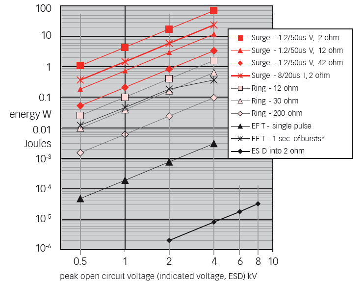
51 Comparision between transient tests 51

52 Comparision of transient standards The energy measure of a given waveform can be described by ESD : waveform magnitude in ns EFT : waveform magnitude in ns Surge : waveform magnitude in µs Surge test is more energetic than ESD and EFT 52
53 53
54 Immunity tests 2 LF and RF phenomena 54
55 RF coupling phenomenum RF emetters 55
56 Radiated immunity IEC
57 Radiated immunity (IEC ) Test purpose Evaluate the performance of a device submitted to radiated RF field Needed instruments: RF generator Power amplifier Directional coupler Power meter Antenna(s) Field-meter 57


58 Radiated immunity IEC Overview Antenna Power amplifi er Field meter Optic fiber Field uniformity Generator GPIB 58
59 Performance Criteria for Immunity Tests Results of immunity tests are classified into four categories: Performance Criteria A Performance within specification limits Performance Criteria B Temporary degradation which is selfrecoverable Performance Criteria C Temporary degradation which requires operator intervention Performance Criteria D Loss of function which is not recoverable 59
60 Equipments Anechoic chamber: of a size adequate to maintain a uniform field of sufficient dimensions with respect to the equipment under test (EUT). Additional absorbers may be used to damp reflections in chambers which are not fully lined. RF signal generator(s) capable of covering the frequency band of interest and of being amplitude modulated by a 1 khz sine wave with a modulation depth of 80%. Power amplifiers: to amplify signal (unmodulated and modulated) and provide antenna drive to the necessary field level. 60
61 Equipments Field generating antennas: biconical, log periodic, horn or any other linearly polarized antenna system capable of satisfying frequency requirements. An isotropic field sensor with adequate immunity of any head amplifier and optoelectronics to the field strength to be measured, and a fibre optic link to the indicator outside the chamber. Associated equipment to record the power levels necessary for the required field strength and to control the generation of that level for testing. 61
62 Frequency range The tests are normally performed without gaps in the frequency range 80 MHz to MHz. Test levels related to the protection against RF emissions from digital radio telephones and other RF emitting devices The tests are normally performed in the frequency ranges 800 MHz to 960 MHz and 1,4 GHz to 6,0 GHz. 62
63 Calibration of field The purpose of field calibration is to ensure that the unifor mity of the field over the test sample is sufficient to ensure the validity of the test results. IEC uses the concept of a uniform field area, which is a hypothetical vertical plane of the field in which variations are acceptably small. A database for setting the required field strength for the immunity test is obtained. The field calibration is valid for all EUTs whose individual faces (including any cabling) can be fully covered by the UFA. 63
64 Calibration of field A full field calibration process should be carried out annually and when changes have been made in the enclosure configuration. The UFA is subdivided into a grid with a grid spacing of 0,5 m (example an 1,5 m 1,5 m UFA). At each frequency, a field is considered uniform if its magnitude measured at the grid points is within 0/+6 db of the nominal value for not less than 75 % of all grid points 64
65 Calibration of field Calibration is performed at 1.8 times the desired field strength. For testing at 10V/m the calibration is run at 18V/m The reason of running a test at 1.8x the level is to verify the RF amplifier has the ability to reach the required field when the 80% 1KHz Amplitude Modulation is applied. An EMC Lab performing testing at multiple levels 1V/m, 3V/m, 10V/m, 30V/m, and/or others, they need only to perform the calibration at 1.8x the max level they will test to and then they can scale the power down. 65

66 AM modulation 66
67 Considerations for equipments choice Select an antenna to use. Frequency range Power handling Beam width & gain Select the correct amplifier Use calculated power to select the correct amplifier Needs to be selected at the 1dB compression point Calculate power requirements Antenna data: based on measured data or gain Calculate out all loses between amplifier and antenna Cables, directional coupler and connectors Intended test distance (1 to 3 meters) 67
68 Performance Criteria for Immunity Tests Results of immunity tests are classified into four categories: Performance Criteria A Performance within specification limits Performance Criteria B Temporary degradation which is selfrecoverable Performance Criteria C Temporary degradation which requires operator intervention Performance Criteria D Loss of function which is not recoverable 68
69 Test levels 69
70 Standards calls 70
71 e 30p d Field strength The resultant field is computed as folows: p is the radiated power d is the distance between the antenna and the field mesure 71
72 Conducted immunity IEC
73 RF coupling phenomenum RF emetters 73
74 Radiated immunity (IEC ) Test purpose Evaluate the performance of a device submitted to conducted electromagnetic field Needed instruments: RF generator Power amplifier Directional coupler Dual power meter Coupling device (CDN, EM clamp, Current clamp, ) 6 db attenuator 74
75 Conducted immunity IEC db Att CDN Power amplifier Generator GPIB 75
76 Coupling devices 76
77 Coupling devices Coupling and decoupling devices shall be used for appropriate coupling of the disturbing signal to the various cables connected to the EUT and for preventing applied test signals from affecting other devices, equipment and systems that are not under test. The coupling and decoupling devices can be combined into one box (a coupling/ decoupling network, CDN) or can consist of several parts. The preferred coupling and decoupling devices are the C DNs, for reasons of test reproducibility and protection of the AE. However, if they are not suitable or available, other injection methods can be used. 77
78 Rules for selecting the injection method 78


79 Types of CDNs 79
80 Performance Criteria for Immunity Tests Results of immunity tests are classified into four categories: Performance Criteria A Performance within specification limits Performance Criteria B Temporary degradation which is selfrecoverable Performance Criteria C Temporary degradation which requires operator intervention Performance Criteria D Loss of function which is not recoverable 80
81 Typical test levels 81
82 Standards calls 82
83 Calibrating the injected level substitution method The power required to give this same stress level is repeat ed in the actual test. For the 150 ohms systems, the required power : vstress/6 or Vstress db (resistive divider) For the 50 ohms systems, the required power : Vstress/2 or Vstress - 6 db (open circuit) 83
84 Immunity to magnetic fields IEC
85 Magnetic field immunity IEC Hz 85
86 Performance Criteria for Immunity Tests Results of immunity tests are classified into four categories: Performance Criteria A Performance within specification limits Performance Criteria B Temporary degradation which is selfrecoverable Performance Criteria C Temporary degradation which requires operator intervention Performance Criteria D Loss of function which is not recoverable 86

87 Standards calls 87
88 Immunity to voltage dips and short interruptions IEC
89 Voltage dips and short interruptions IEC Power fail generator EUT Variac 89
90 Performance Criteria for Immunity Tests Results of immunity tests are classified into four categories: Performance Criteria A Performance within specification limits Performance Criteria B Temporary degradation which is selfrecoverable Performance Criteria C Temporary degradation which requires operator intervention Performance Criteria D Loss of function which is not recoverable 90
91 Voltage dips and short interruptions EN Overview 91
92 Emission tests 92
93 Emission CISPR 22 / EN
94 ITE functionnality An ITE is able to perform: Receive data from an external source; Perform treatments Provide a result 94
95 Equipements Classes (1) The class B ITE is intended primarily for use in a residential area and may include: the devices having no fixed location of use, such as portable battery powered or batteries incorporated; the telecommunication terminal equipment supplied by a telecommunications network; personal computers and auxiliary devices connected to them. 95
96 Equipements Classes(2) Class A consists of all other ATI complying with the limits of disturbance of class A but not those of class B. Can be used in commercial or industrial environment. 96
97 Conducted emissions CISPR22/EN
98 Required equipments For power supply lines: LISN (Lines Impedance Stabilisation Network) For data lines: ISN (Impedance Stabilisation Network) Transient limiter EMI receiver or spectrum analyser EMI software
99 Conducted emission CISPR22/ EN GPIB LISN Transient limiter EMI receiver or spectrum analyser 99
100 Conducted emission test setup 100
101 Conducted emissions Measurement of conducted electromagnetic disturbances must be made: by means of a measuring receiver with a peak detector in the frequency range 9 khz to 30 MHz.
102 Conducted limits The EUT shall respect the limits of Tables 1 and 2 which include limits on the mean value and limits on quasi-peak value A receiver is used to average value detection and a quasi-peak detector 102
103 Decision tree
104 Emissison thresholds
105 Measure dbµv conduit CLASSE B QP conduit CLASSE B Average Frequency (MHz)
106 Radiated emissions CISPR22/EN 55022
107 Required equipments Receiving antennas EMI receiver or spectrum analyser EMI software
108 Radiated emission - CISPR22/EN m 0.8 m EMI receiver or spectrum analy ser GPIB 108
109 Test setup for radiated emission
110 Radiated emission The measurement of radiated electromagnetic disturbance s must be performed by means of a measuring receiver equipped with a quasi-peak detector in the frequency range 30 MHz to 1 GHz or 6 GHz. A receiving antenna, associated with a measuring receiver, is placed at a specific distance from the EUT (test equipme nt) 110
111 Radiated EM field measure Peak measure to determine the most perturbing condition Determining antenna polarisation that most generate disturbances For every frequency : Determine the antenna hight that captures the maximum measured level Determine the angle that generated the maximum of disturbances 111
112 Radiated field measurement Measurement antenna 1 to 4 m EUT Reflecting ground 112
113 Open area test site Site de mesure en espace libre 113
114 Measure dbµv/m Limite Classe B Link to the standard EN Frequency (MHz)
115 Harmonics emission IEC
116 Harmonics emission Causes They are generated by devices that consume nonsinusoidal current, such as fluorescent lighting or power supplies (equipment components nonlinear diodes, thyristors...) Effects Heating cables (neutral wire three-phase) Premature aging of electronic components 116
117 Harmonics emission IEC EUT Stable source Harmonics analyser 117
118 DPA connection 118
119 Spectral effects Temporal Spectral 119
120 Time vs frequency representation 120
121 Test classes There are 4 different classes in the EN that have different limit values: Class A: Balanced 3-phase equipment, household appliances excluding equipment identified as class D, tools, excluding portable tools, dimmers for incandescent lamps, audio equipment, and all other equipment, except that stated in one of the following classes. Class B: Portable tools, arc welding equipment which is not professional equipment Class C: Lighting equipment. Class D: PC, PC monitors, radio, or TV receivers. Input power P 600 W. 121
122 122
123 Test procedure 1. Select the correct test observation period ( Table 6.1) of the EUT ( min. 10s) 2. Enter the following data (only Class C and D ), if available Class D : Max. Power or Class C : Maximum Fund. current and Max Power Factor 1. Start the measuring 2. Upload the data to the computer 3. Select the Class A...D 4. Start the evaluation 5. Print the report 123
124 Data flow The DPA measures simultaneeusly on all 2 or 6 input channels, carries out the Fourier transformation in real time stores all data on the internal hard disk. When measuring fluctuations the system generates approx. 1 Mbyte data per minute on the hard disk. The upload of a 2.5 minute measurement needs less than 20 seconds. An internal timer in the DPA stops automatically the measurement. The data are ready for upload on the internal hard disk. The DPA will overwrite the measurement by starting the next measurement. 124
125 Test parameters 125
126 Test result Limit values are indicated and harmonics exceeding the specified limit are marked in red colour. 126
127 Flickers emission IEC
128 Flicker Flicker standards are imposed to limit voltage variations caused by loads connected to the supply network that would cause lights connected at the same circuit to flicker. For device single phase up to 16A the standard EN IEC sets the limits for voltage fluctuation caused by electrical apparatus. 128
129 Flickers emission IEC EUT Stable source Flickers analyser 129
130 130
131 Flickers test The flicker analysis is based on a standards library including the basic standards but also, and even more important, product-specific Requirements such as hair dryers and vacuum cleaners. The actual flicker values are continously displayed. A test can be stopped once a limit is exceeded. This could, in case, safe valuable test time. 131
132 Flickers parameters After the flicker measurement the values of dc, dmax, dt are displayed on the screen. dc : Relative continuous voltage variation ( must be smaller than 3.3% ) The dc value is a % value relative to the nominal AC voltage of 230V AC. dmax: Max. relative voltage variation (must be smaller than 4% or 6.7%). The dmax value is a % value relative to the nominal AC voltage of 230V AC. dt: Time with voltage variation >3.3%. During max. 500ms the voltage is allowed to be above the 3.3% limit. 132
133 Limits The limits shall be applicable to voltage fluctuations and flicker at the supply terminals of the equipment under test: The following limits apply: the value of Pst shall not be greater than 1,0; the value of Plt shall not be greater than 0,65; the value of d(t) during a voltage change shall not exceed 3, 3 % for more than 500 ms; the relative steady-state voltage change, dc, shall not excee d 3,3 %; 133
134 Limits the maximum relative voltage change dmax, shall not exceed a) 4 % without additional conditions; b) 6 % for equipment which is: switched manually, or switched automatically more frequently than twice per day c) 7 % for equipment which is attended whilst in use switched on automatically, or is intended to be switched on manually, no more than twice per day, and also has either a delayed restart 134
135 Test results 135
136 Example of a product standard EN
137 Example of a generic standard EN
138 Example of a test report Link 138
139 ITU Training on Conformance and Interoperability for ARB Region CERT, 2-6 April 2013, EMC standards Presented by: Karim Loukil & Kaïs Siala 139
Rated Power(W) 8W 2. EG-LED0840-01 8W 3. EG-LED1027-01 10W
 8W 2. EG-LED0840-01 8W 3. EG-LED1027-01 10W") 14713221 001 Seite 2 von 37 Page 2 of 37 Model List: No Model Rated Voltage(V) 1. EG-LED0827-01 Rated Power(W) 8W 2. EG-LED0840-01 8W 3. EG-LED1027-01 10W 4. EG-LED1040-01 AC 100-240V, 10W 5. EG-LED1027-02
14713221 001 Seite 2 von 37 Page 2 of 37 Model List: No Model Rated Voltage(V) 1. EG-LED0827-01 Rated Power(W) 8W 2. EG-LED0840-01 8W 3. EG-LED1027-01 10W 4. EG-LED1040-01 AC 100-240V, 10W 5. EG-LED1027-02
TEST REPORT EN 55014-2 (1997) +A1 (2001)
 +A1 (2001)") Page 1 of 23 TEST REPORT EN 55014-2 (1997) +A1 (2001) Electromagnetic compatibility - Requirements for household appliances, electric tools and similar apparatus Part 2: Immunity Report Reference No....
Page 1 of 23 TEST REPORT EN 55014-2 (1997) +A1 (2001) Electromagnetic compatibility - Requirements for household appliances, electric tools and similar apparatus Part 2: Immunity Report Reference No....
SHENZHEN GEMBIRD ELECTRONICS LTD EMC REPORT
 Shenzhen BST Technology Co., Ltd. SHENZHEN GEMBIRD ELECTRONICS LTD EMC REPORT Prepared For : Product Name: Model : Prepared By : SHENZHEN GEMBIRD ELECTRONICS LTD 5th Floor, Building B, Shifeng Industry
Test Report. Prepared for: Technologic Systems, Inc. Model: TS-8820
 Test Report Prepared for: Technologic Systems, Inc. Model: TS-8820 Description: Single Board Computer with Analog and Digital Inputs and Outputs, Relays, and RS-232/485 Ports To IEC 61000-6-1 (2005-03)
TEST REPORT Rapporto di prova EMC N 060406. Test facility site: via L. da Vinci, 92, Caravaggio (BG), Italy Sede laboratorio
, Italy Sede laboratorio") TEST REPORT Rapporto di prova EMC N 060406 EUT: Organic Carbon Analyzer Analiuzzatore Carbonio Organico Model: TOCMETER Serial N : TM602 Client: TRE-ESSE s.r.l. Cliente Piazzale Europa 8 16036 Recco (GE),
TEST REPORT Rapporto di prova EMC N 060406 EUT: Organic Carbon Analyzer Analiuzzatore Carbonio Organico Model: TOCMETER Serial N : TM602 Client: TRE-ESSE s.r.l. Cliente Piazzale Europa 8 16036 Recco (GE),
Standard: EN 61000-4-2 :1995, EN 61000-4-3 :1996, ENV 50204 :1993, & EN 61000-4-4 :1995 Solid State Energy Meter
 Standard: EN 61000-4-2 :1995, EN 61000-4-3 :1996, ENV 50204 :1993, & EN 61000-4-4 :1995 Model: Solid State Energy Meter Prepared for: Analog Devices, Inc. 804 Woburn Street Wilmington, MA 01887 Date of
Test Report #: 1981-3 Date: April 8, 2005
 Test Report #: 1981-3 Date: April 8, 2005 CERTIFICATE #2316.01 Issued To: Bill Burks American Power Conversion 85 Rangeway Road North Billerica, MA 01862 USA 978-670-2440 Product Name/Description Model
EMC STANDARDS STANDARDS AND STANDARD MAKING BODIES. International. International Electrotechnical Commission (IEC) http://www.iec.
 http://www.iec.") EMC STANDARDS The EMC standards that a particular electronic product must meet depend on the product application (commercial or military) and the country in which the product is to be used. These EMC regulatory
EMC STANDARDS The EMC standards that a particular electronic product must meet depend on the product application (commercial or military) and the country in which the product is to be used. These EMC regulatory
EMC TEST REPORT For. Shenzhen Homelux Security Equipment Co., Ltd. Auto Dialer. Model No.: HX-GD20
 EMC TEST REPORT For Shenzhen Homelux Security Equipment Co., Ltd Auto Dialer Model No.: HX-GD20 Prepared for : Shenzhen Homelux Security Equipment Co., Ltd Address : 4 th Floor, Building 5, Jiademaluan
EMC Test for Compliance with EU EMC Directive 2004/108/EU
 EMC Test for Compliance with EU EMC Directive 2004/108/EU Partial Test 12-12-2012 Standards Description EN 55022:2011 Information technology equipment - Radio disturbance characteristics - Limits and methods
MYRICOM, INC. TEST REPORT FOR THE LAN INTERFACE CARD, M3F2-PCIXE-2
 MYRICOM, INC. TEST REPORT FOR THE LAN INTERFACE CARD, M3F2-PCIXE-2 EN55024 (1998), EN61000-3-2 (2001), EN61000-3-3 (1995 W/A1: 98), EN55022 (1998) CLASS A, CISPR 22 (1997) CLASS A & FCC PART 15 SUBPART
Electromagnetic Compatibility Test Report Test results of Floww equipment
 Electromagnetic Compatibility Test Report Test results of Floww equipment Reference number Status test report Brand Model number : 10C00357RPT01.doc : Final : Floww : mobilefloww screenfloww pocketfloww
EMC TEST REPORT For. Webcam. Model Number: CAM67U
 EMC TEST REPORT For Webcam Model Number: CAM67U Prepared for : Gembird Europe B.V. Wittevrouwen 56, 1358CD Almere, The Netherlands. Phone: +31-36-5211588 Prepared By : Shenzhen Meihua Electronic Technology
Declaration of Conformity.
 Declaration of Conformity. Type of equipment: Brand Name /Trade Mark: Type designation /model: Applicant: Network Camera SAMSUNG SND6011RP SAMSUNG TECHWIN CO., LTD. In accordance with the following Directives:
Declaration of Conformity.
 Declaration of Conformity. Type of equipment: Brand Name /Trade Mark: Type designation /model: Applicant: PTZ CAMERA SAMSUNG SCP2371HP SAMSUNG TECHWIN CO., LTD. In accordance with the following Directives:
AN96-07. Surging Ideas TVS Diode Application Note PROTECTION PRODUCTS. TRANSIENT IMMUNITY STANDARDS: IEC 61000-4-x
 TRANSIENT IMMUNITY STANDARDS: IEC 61000-4-x On January 1, 1996, exports into Europe began facing some tough transient immunity standards. The International Electrotechnical Commission (IEC), a worldwide
Variant Model No. The equipment under test has found to be compliant with the applied standards. (Refer to the attached test result for more detail.
 EMC TEST REPORT Project No. LBE091881 Revision No. NONE Name of organization Samsung Electronics Co., Ltd. Applicant Address 416 Maetan 3-Dong,Yeongtong-Gu,Suwon-Si, Gyeonggi-Do, 443-742 Korea Date of
Prepared for Dorman Long Engineering Technology Consultant (Shanghai) Co., Ltd.
 Co., Ltd.") www.ecmg-global.com EMC TEST REPORT On Model Name: DL-P40 Computer Control System Model Number: Release 3.0 Hardware and Software Brand Name: Dorman Long Technology Ltd. Trade Mark: DLT Prepared for Dorman
www.ecmg-global.com EMC TEST REPORT On Model Name: DL-P40 Computer Control System Model Number: Release 3.0 Hardware and Software Brand Name: Dorman Long Technology Ltd. Trade Mark: DLT Prepared for Dorman
NMI M 6-2 Electricity Meters. Part 2: Test Report Format
 NMI M 6-2 Electricity Meters Part 2: Test Report Format Commonwealth of Australia 2010 First edition September 2010 National Measurement Institute Bradfield Road, Lindfield, NSW 2070 PO Box 264, Lindfield,
EN 301 489-17 v1.2.1 TEST REPORT FOR. 802.11ag/Draft 802.11n WLAN PCI-E Mini Card MODEL NUMBER: BCM94322MC REPORT NUMBER: 07U11529-5
 EN 301 489-17 v1.2.1 TEST REPORT FOR 802.11ag/Draft 802.11n WLAN PCI-E Mini Card MODEL NUMBER: BCM94322MC REPORT NUMBER: 07U11529-5 ISSUE DATE: JANUARY 29, 2008 Prepared for BROADCOM CORPORATION 190 MATHILDA
Declaration of Conformity.
 Declaration of Conformity. Type of equipment: Brand Name /Trade Mark: Type designation /model: Applicant: Network Camera SAMSUNG SNP-6200RHP SAMSUNG TECHWIN CO., LTD. In accordance with the following Directives:
Declaration of Conformity.
 Declaration of Conformity. Type of equipment: Brand Name /Trade Mark: Type designation /model: Applicant: PTZ CAMERA SAMSUNG SNP-5300P SAMSUNG TECHWIN CO., LTD. In accordance with the following Directives:
LAB 1 TECHNICAL DOC 3 IN ONE LAB DEVICE. Velleman Legen Heirweg 33 9890 Gavere Belgium
 LAB 1 TECHNICAL DOC 3 IN ONE LAB DEVICE Velleman Legen Heirweg 33 9890 Gavere Belgium SPECIFICATIONS DIGITAL MULTIMETER 3 1/2 backlit LCD Automatic polarity indication DC voltage 200mV to 600V in 5 steps
EMC TEST REPORT. Page: 1 of 38. Reference No.: WT08010091-S-E
 Page: 1 of 38 EMC TEST REPORT Reference No. Applicant Address : WT08010091-S-E : Gembird Electronics Ltd. : Room 1709 A, News Building, #2 Shennan Zhong Lu, Shenzhen, China Equipment Under Test (EUT) :
Rules for Classification and Construction Additional Rules and Guidelines
 VI Rules for Classification and Construction Additional Rules and Guidelines 7 Guidelines for the Performance of Type Approvals 2 Test Requirements for Electrical / Electronic Equipment and Systems Edition
ELECTROMAGNETIC COMPATIBILITY TEST. Report reference N R-255 EMC 2010
 ELECTROMAGNETIC COMPATIBILITY TEST Report reference N R-255 EMC 2010 Constructor. Address Reference person. C LUCE S.r.l. Via Marmolada 5/11 20060 Truccazzano (MI) Italy ---- Product....... Model......
TEST REPORT. Please refer to section 3 of this report which indicates which item was actually tested and which were electrically identical.
 198 Kezhu Road, Scientech Park, Guangzhou Economic & Technological Development District, Guangzhou, China 510663 Telephone: +86 (0) 20 82155555 Fax: +86 (0) 20 82075059 Email: sgs_internet_operations@sgs.com
Declaration of Conformity.
 Declaration of Conformity. Type of equipment Brand Name /Trade Mark Type designation /model Applicant Network Camera SAMSUNG SND-5083P SAMSUNG TECHWIN CO., LTD. In accordance with the following Directives
Declaration of Conformity.
 Declaration of Conformity. Type of equipment: Brand Name /Trade Mark: Type designation /model: Applicant: Network Camera SAMSUNG SNO-6011RP SAMSUNG TECHWIN CO., LTD. In accordance with the following Directives:
Harmonics and Noise in Photovoltaic (PV) Inverter and the Mitigation Strategies
 Inverter and the Mitigation Strategies") Soonwook Hong, Ph. D. Michael Zuercher Martinson Harmonics and Noise in Photovoltaic (PV) Inverter and the Mitigation Strategies 1. Introduction PV inverters use semiconductor devices to transform the
Soonwook Hong, Ph. D. Michael Zuercher Martinson Harmonics and Noise in Photovoltaic (PV) Inverter and the Mitigation Strategies 1. Introduction PV inverters use semiconductor devices to transform the
Single-phase (220...240 V) voltage monitoring: Undervoltage Overvoltage Window mode (overvoltage + undervoltage) Voltage fault memory selectable
 voltage monitoring: Undervoltage Overvoltage Window mode (overvoltage + undervoltage) Voltage fault memory selectable") Features 70.11 70.31 70.41 Electronic voltage monitoring relays for single and three-phase applications Multifunctional types, providing the flexibility of monitoring Undervoltage, Overvoltage, Window
Features 70.11 70.31 70.41 Electronic voltage monitoring relays for single and three-phase applications Multifunctional types, providing the flexibility of monitoring Undervoltage, Overvoltage, Window
Cond-IS RF Conducted Immunity System
 Cond-IS RF Conducted Immunity System About RF Conducted Immunity In the global contest of EMC testing for residential and industrial EUTs (Equipments Under Test) RF Conducted Immunity compliance verification
Power Supply Unit, Primary Switched, Narrow Design MINI-PS-12-24DC/24DC/1
 Power Supply Unit, Primary Switched, Narrow Design MINI POWER provides: Extra narrow design with widths of 22.5 mm, 45 mm, and 67.5 mm (0.886, 1.772, and 2.657 in.) Global use due to a wide-range input
Clamp Filters that Suppress Emission Noise Provide Immunity Against Surge Noise
 TDK EMC Technology Product Section Clamp Filters that Suppress Emission Noise Provide Immunity Against Surge Noise TDK Shonai Corporation Satoru Saito Reduce Emission Noise from Cables Even if an electronic
15 Series - Electronic step relay and dimmer. Features 15.91 15.51 15.81 SERIE
 Series - Electronic step relay and dimmer SERIE Features.91.51.81 Electronic step relay and dimmer for control of lighting levels Suitable for incandescent and halogen lighting loads (with or without transformer
CE-EMC TEST- REPORT TEST REPORT NUMBER: EFSN14040316E-E01 EUROFINS TESTING TECHNOLOGY (SHENZHEN) CO., LTD.
 CO., LTD.") EUROFINS TESTING TECHNOLOGY (SHENZHEN) CO., LTD. CE-EMC TEST- REPORT TEST REPORT NUMBER: EFSN14040316E-E01 Phone: +86-755-83585700 3A, F1.6, Tianfa Building, Tian an Cyber Park, Fax: +86-755-83585701 Futian
EUROFINS TESTING TECHNOLOGY (SHENZHEN) CO., LTD. CE-EMC TEST- REPORT TEST REPORT NUMBER: EFSN14040316E-E01 Phone: +86-755-83585700 3A, F1.6, Tianfa Building, Tian an Cyber Park, Fax: +86-755-83585701 Futian
STRATO LED Drivers 70W, Single output
 Features STRATO switch mode driver technology is designed to generate one constant current output from a wide range AC input. The size and performance of these products make them the ideal choice for LED
Current Probes. User Manual
 Current Probes User Manual ETS-Lindgren L.P. reserves the right to make changes to any product described herein in order to improve function, design, or for any other reason. Nothing contained herein shall
Electromagnetic Compatibility Considerations for Switching Power Supplies
 Electromagnetic Compatibility Considerations Characterization of the EMI problem requires understanding the interference source Switching power supplies generate Electromagnetic Interference (EMI) by virtue
Electronic timer CT-AHD.12 OFF-delayed with 1 c/o (SPDT) contact
 contact") Data sheet Electronic timer CT-AHD.12 OFF-delayed with 1 c/o (SPDT) contact The CT-AHD.12 is an electronic time relay with OFF-delay. It is from the CT-D range. With their MDRC profile and a width of only
Data sheet Electronic timer CT-AHD.12 OFF-delayed with 1 c/o (SPDT) contact The CT-AHD.12 is an electronic time relay with OFF-delay. It is from the CT-D range. With their MDRC profile and a width of only
UNDERSTANDING POWER FACTOR AND INPUT CURRENT HARMONICS IN SWITCHED MODE POWER SUPPLIES
 UNDERSTANDING POWER FACTOR AND INPUT CURRENT HARMONICS IN SWITCHED MODE POWER SUPPLIES WHITE PAPER: TW0062 36 Newburgh Road Hackettstown, NJ 07840 Feb 2009 Alan Gobbi About the Author Alan Gobbi Alan Gobbi
AVX EMI SOLUTIONS Ron Demcko, Fellow of AVX Corporation Chris Mello, Principal Engineer, AVX Corporation Brian Ward, Business Manager, AVX Corporation
 AVX EMI SOLUTIONS Ron Demcko, Fellow of AVX Corporation Chris Mello, Principal Engineer, AVX Corporation Brian Ward, Business Manager, AVX Corporation Abstract EMC compatibility is becoming a key design
Predicting radiated emissions from cables in the RE02/RE102/DO- 160/SAE J113-41 test set up, using measured current in NEC and simple TX equations.
 Predicting radiated emissions from cables in the RE02/RE102/DO- 160/SAE J113-41 test set up, using measured current in NEC and simple TX equations. D. A. Weston RE02Tx.rep 14-6-2004 NARTE Certified EMC
40 Years of experience in EMC testing
 40 Years of experience in EMC testing Your reference laboratory for tests of generation, propagation and reception of electromagnetic energy in civil, military and industrial applications. CESI has been
EMC for test engineers by. Laplace Instruments Ltd. An introduction to the world of EMC compliance testing for engineers new to the topic.
 EMC for test engineers by An introduction to the world of EMC compliance testing for engineers new to the topic. Index: Introduction Page 3 The EU Directive Page 3 The EMC Standards. Page 3 Compliance
Dual Chamber Temporary External Pacemaker
 5392 Dual Chamber Temporary External Pacemaker Electromagnetic Compatibility Declaration Caution: Federal law (USA) restricts this device to sale by or on the order of a physician. The following list includes
FCC PART 15B CLASS A MEASUREMENT AND TEST REPORT
 FCC PART 15B CLASS A MEASUREMENT AND TEST REPORT For SAMBO HI TECH CO., LTD. 616-15, GANSUK4-DONG, NAMDONG-GU, INCHUN 405-810, KOREA Model: LSR700, SCI545HV1EF, SCI545HVEF This Report Concerns: Original
DRTS 33. The new generation of advanced test equipments for Relays, Energy meters, Transducers and Power quality meters
 The new generation of advanced test equipments for Relays, Energy meters, Transducers and Power quality meters Testing all relay technologies: electromechanical, solid state, numerical and IEC61850 Manual
CONTROLS DATA MANAGEMENT PROCESS AUTOMATION EUROCUBE. General purpose single phase thyristors and solid state relays Product data.
 425 CONTROLS DATA MANAGEMENT PROCESS AUTOMATION EUROCUBE General purpose single phase thyristors and solid state relays Product data abc 425 EUROCUBE A complete range of low cost solid state relays and
38 Series - Relay interface modules 0.1-2 - 3-5 - 6-8 A
 38 Series - Relay interface modules 0.1-2 - 3-5 - 6-8 A Common features Instant ejection of relay by plastic retaining clip Integral coil indication and protection circuit EMR Electromechanical Relays
Electromagnetic Compatibility (EMC) Low-Frequency Standards. Standards on Low-Frequency Emission: IEC 61000-3-2
 Low-Frequency Standards. Standards on Low-Frequency Emission: IEC 61000-3-2") Electromagnetic Compatibility (EMC) Low-Frequency Standards Summary IEC 61000-3-2: Limits for harmonic current emissions (equipment input current 16A per phase) IEC 61000-3-4: Limitation of emission of
Electromagnetic Compatibility (EMC) Low-Frequency Standards Summary IEC 61000-3-2: Limits for harmonic current emissions (equipment input current 16A per phase) IEC 61000-3-4: Limitation of emission of
Waveguide Access Point WGA631. Product Guide
 Waveguide Access Point Product Guide Waveguide Access Point Contents 1. Description............................ 3 2. Application............................ 3 3. Technical data... 4 4. Physical interfaces......................
Technical Article MS-2443
 . MS-2443 Safeguard Your RS-485 Communication Networks from Harmful EMC Events by James Scanlon, Senior Evaluation Engineer, Analog Devices, Inc., and Koenraad Rutgers, Senior Field Applications Engineer,
TRACTION NETWORK MONITORING AND PROTECTION SYSTEM SMTN-3 CITY ELECTRIC TRANSPORT RAILWAYS METRO INDUSTRY
 TRACTION NETWORK MONITORING AND PROTECTION SYSTEM SMTN-3 CITY ELECTRIC TRANSPORT RAILWAYS METRO INDUSTRY 2 TRACTION NETWORK MONITORING AND PROTECTION SYSTEM Traction network monitoring and protection system,
IEC 1000-4-2 ESD Immunity and Transient Current Capability for the SP72X Series Protection Arrays
 IEC 00-4-2 ESD Immunity and Transient Current Capability for the SP72X Series Protection Arrays Application Note July 1999 AN9612.2 Author: Wayne Austin The SP720, SP721, SP723, and SP724 are protection
EMC Standards: Standards of good EMC engineering
 Electromagnetic Compatibility (EMC) IEEE Definition Origin, control, and measurement of electromagnetic effects on electronic and biologic systems. IEEE EMC Society Areas of Interest EMC Standards: Standards
PD30ETB20xxIS. Photoelectrics, Background Suppression reflective with IR light. Main features. Description
 Photoelectrics, Background Suppression reflective with IR light Main features Description The PD30ET... stainless steel sensors are built with high-quality materials and designed for harsh environments.
38 SERIES. Relay interface modules 0.1-2 - 3-5 - 6-8 - 16 A. EMR Electromechanical Relays. Common features. SSR Solid State Relays. 6.
 38 Relay interface modules 0.1-2 - 3-5 - 6-8 - 16 A 38 Common features Instant ejection of relay by plastic retaining clip Integral coil indication and protection circuit 6.2 mm wide EMR - DC, AC or AC/DC
Energy Management Energy Meter Type EM23 DIN
 Energy Management Energy Meter Type EM23 DIN Class 1 (kwh) according to EN62053-21 Class B (kwh) according to EN50470-3 Class 2 (kvarh) according to EN62053-23 Accuracy ±0.5 RDG (current/voltage) Energy
UNDERSTANDING AND CONTROLLING COMMON-MODE EMISSIONS IN HIGH-POWER ELECTRONICS
 Page 1 UNDERSTANDING AND CONTROLLING COMMON-MODE EMISSIONS IN HIGH-POWER ELECTRONICS By Henry Ott Consultants Livingston, NJ 07039 (973) 992-1793 www.hottconsultants.com hott@ieee.org Page 2 THE BASIC
IEC and CISPR Standards
 IEC and CISPR Standards With thanks to Gideon Wiid, PhD student, and Paul van der Merwe EE Eng, 2 May, 2007 EMC Definition: Electromagnetic compatibility itself is defined as [1]: "the ability of an equipment
SCOPE OF ACCREDITATION TO ISO/IEC 17025:2005 1
 SCOPE OF ACCREDITATION TO ISO/IEC 17025:2005 1 BUREAU VERITAS ADT (SHANGHAI) CORPORATION 2F, Building C, No. 1618. Yishan Road 201103 Shanghai, CHINA Ms. Mary Gu (Authorized Representative) Phone: 86 21
The EMI-Receiver according to CISPR 16-1-1
 Author: Dipl. -Ing. Dieter Schwarzbeck Schwarzbeck Mess-Elektronik An der Klinge 29 D-69250 Schönau / Germany Tel.: +49 6228 1001 Fax.:+49 6228 1003 support@schwarzbeck.de www.schwarzbeck.de Requirements
Telephone- and leased line modem for industrial applications TD-36
 Telephone- and leased line modem for industrial applications TD-36 Modem for industrial PSTN- and leased line applications The TD-36 is an analogue V.34 PSTN modem as well as an industrial 2-wire leased
White Paper: Electrical Ground Rules
 Acromag, Incorporated 30765 S Wixom Rd, Wixom, MI 48393 USA Tel: 248-295-0880 Fax: 248-624-9234 www.acromag.com White Paper: Electrical Ground Rules Best Practices for Grounding Your Electrical Equipment
TM7BDM8B expansion block - TM7 - IP67-8 DI/DO - 24V DC - 0.5 A - M8 connector
 Product datasheet Characteristics TM7BDM8B expansion block - TM7 - IP67-8 DI/DO - 24V DC - 0.5 A - M8 connector Main Range of product Product or component type Range compatibility Enclosure material Bus
1587/1577. Insulation Multimeters. Technical Data. Two powerful tools in one.
 1587/1577 Insulation Multimeters Technical Data Two powerful tools in one. The Fluke 1587 and 1577 Insulation Multimeters combine a digital insulation tester with a full-featured, true-rms digital multimeter
Espotel Test Laboratory Services. November 20, 2014
 Espotel Test Laboratory Services November 20, 2014 Espotel Laboratory Services EMC, ESD, RF testing EMC chamber for radiated emissions and immunity testing Radiated interoperability for LTE, GSM/3G, WLAN
38 Series - Relay interface modules 0.1-2 - 3-5 - 6-8 - 16 A
 38 Series - Relay interface modules 0.1-2 - 3-5 - 6-8 - 16 A 38 SERIES Common features Instant ejection of relay by plastic retaining clip Integral coil indication and protection circuit EMR Electromechanical
TEST REPORT. CONCLUSION: The submitted sample was found to COMPLY with the test requirement
 TEST REPORT Applicant Address Shenzhen Gembird Electronics Ltd. 5F, Building B, Shi-Feng Industrial Zone, Hua-Ning Rd., Xin-Wei Village, Da-Lang Street, Long-Hua, Bao-An Area, Shenzhen 518109, Guangdong
Type: EASY719 DC RC Article No.: 274119. Ordering information Relay outputs Quantity 6 Power supply V DC 24 V DC. Description
 Type: EASY719 DC RC Article.: 274119 Ordering information Relay outputs Quantity 6 Power supply V DC 24 V DC Description 12 digital inputs (4 inputs available as analog inputs) 6 relay outputs LCD display
RX-AM4SF Receiver. Pin-out. Connections
 RX-AM4SF Receiver The super-heterodyne receiver RX-AM4SF can provide a RSSI output indicating the amplitude of the received signal: this output can be used to create a field-strength meter capable to indicate
Constructing a precision SWR meter and antenna analyzer. Mike Brink HNF, Design Technologist.
 Constructing a precision SWR meter and antenna analyzer. Mike Brink HNF, Design Technologist. Abstract. I have been asked to put together a detailed article on a SWR meter. In this article I will deal
AN1200.04. Application Note: FCC Regulations for ISM Band Devices: 902-928 MHz. FCC Regulations for ISM Band Devices: 902-928 MHz
 AN1200.04 Application Note: FCC Regulations for ISM Band Devices: Copyright Semtech 2006 1 of 15 www.semtech.com 1 Table of Contents 1 Table of Contents...2 1.1 Index of Figures...2 1.2 Index of Tables...2
Measurement of RF Emissions from a Final Coat Electronics Corrosion Module
 Engineering Test Report No. 37802-02 Rev. A Measurement of RF Emissions from a Final Coat Electronics Corrosion Module For : Canadian Auto Preservation, Inc. 390 Bradwick Drive Concord, Ontario CANADA
Three-phase monitoring relay CM-PFE
 Data sheet Three-phase monitoring relay CM-PFE The CM-PFE is a three-phase monitoring relay that monitors the phase parameter phase sequence and phase failure in three-phase mains. 2CDC 251 005 S0012 Characteristics
Charged cable event. 1 Goal of the ongoing investigation. 2 Energy sources for the CDE. Content
 Charged cable event David Pommerenke, david_pommerenke@hp.com, 916 785 4550 Last update: Feb.23, 2001 Content Goal Energy sources, which may lead to CDE. Complexity of the different discharge modes. Possible
Applications in EMC testing. Outline. Antennas for EMC Testing. Terminology
 Antennas for EMC Testing Zhong Chen ETS-Lindgren 1301 Arrow Point Drive Cedar Park, TX 78613 Zhong.Chen@ets-lindgren.com Outline EMC Terms and Definitions Typical EMC Antennas Calibration of EMC Antennas
1+1 PROTECTION WITHOUT RELAYS USING IDT82V2044/48/48L & IDT82V2054/58/58L HITLESS PROTECTION SWITCHING
 1+1 PROTECTION WITHOUT RELAYS USING IDT82V2044/48/48L & IDT82V2054/58/58L APPLICATION NOTE AN-357 1.0 INTRODUCTION In today's highly competitive market, high quality of service, QOS, and reliability is
MasterINTERFACE 39 Series - Relay interface modules
 MasterINTERFACE 39 Series - Relay interface modules Common features Space saving 6.2 mm wide Connections for 16-way jumper link Integral coil indication and protection circuit Secure retention and easy
RISH EM 3490 DS Dual Source Energy Meter RISH EM 3490 DS. Application : Product Features:
 Application : RISH Master 3490 DS measures important electrical parameters of Utility (in normal mode) & Generators (in Power back up) in three phase and single phase Network & replaces the multiple analog
Power Quality Issues, Impacts, and Mitigation for Industrial Customers
 Power Quality Issues, Impacts, and Mitigation for Industrial Customers By Kevin Olikara, Power and Energy Management Products Rockwell Automation, Inc. Now, more than ever, electronic equipment and computing
DDX 7000 & 8003. Digital Partial Discharge Detectors FEATURES APPLICATIONS
 DDX 7000 & 8003 Digital Partial Discharge Detectors The HAEFELY HIPOTRONICS DDX Digital Partial Discharge Detector offers the high accuracy and flexibility of digital technology, plus the real-time display
ABB 1. Three-phase monitoring relay CM-PFS. Data sheet. Features. Approvals. Marks. Order data. Order data - Accessories. Application.
 1SR 430 824 F9300 Features Monitoring of three-phase mains for phase sequence and failure Powered by the measuring circuit 2 c/o (SPDT) contacts 1 LED for status indication Approvals R: yellow LED - relay
Rack mounted telephone- and leased line modem for industrial applications
 Rack mounted telephone- and leased line modem for industrial applications TR-6 Rack modem for industrial PSTNand /-wire leased line applications The TR-6 is an analogue V. 9 -rack PSTN modem as well as
SURGE PROTECTIVE DEVICES
 SURGE PROTECTIVE DEVICES 1. INTRODUCTION In order to ensure safety of people, protection of equipment and, to a certain extent, continuity of supply, insulation co-ordination aims at reducing the likelihood
CERTIFICATE. Issued Date:May. 18, 2006 Report No.: 065L043-IT-CE-P07V03. MGate MB318n(-T) (n=0~9,a~z)
 (n=0~9,a~z)") CERTIFICATE Issued Date:May. 18, 2006 Report No.: 065L043-IT-CE-P07V03 This is to certify that the following designated product Product Trade name Model Number : 1 Port Device Server : Moxa : NPort 5150(-T),
CERTIFICATE Issued Date:May. 18, 2006 Report No.: 065L043-IT-CE-P07V03 This is to certify that the following designated product Product Trade name Model Number : 1 Port Device Server : Moxa : NPort 5150(-T),
7.5 Watt AC-DC Switch Power Supply
 MAIN FEATURES: 7.5W Small Compact Size PCB Mount Single Output Regulated Output Range : 3.3VDC 24VDC Input Range : 85VAC 265VAC/47 63Hz Or 120VDC 370VDC Very Low Standby Power Consumption < 0.15W Better
80 Series - Modular timers 16 A. Features 80.01 80.11
 80 Series - Modular timers 16 A Features 80.11 Multi-function and mono-function timer range - Multi-function & multi-voltage 80.11 - On-delay, multi-voltage 17.5 mm wide Six time scales from 0.1s to 24h
Verizon NEBS TM Compliance: Data Center Equipment NEBS Requirements Verizon Technical Purchasing Requirements VZ.TPR.9703 Issue 2, March 2012
 Verizon NEBS TM Compliance: Data Center Equipment NEBS Requirements Verizon Technical Purchasing Requirements VZ.TPR.9703 Issue 2, March 2012 CHANGE CONTROL RECORD: Version Date Action* Reason for Revision
DUAL%CHANNEL BROADBAND%LINEAR%AMPLIFIER Model&A800D
 ELECTRONICS AB DUAL%CHANNEL BROADBAND%LINEAR%AMPLIFIER Model&A800D & HIGH&VOLTAGE& FIXED&GAIN& BROADBAND & 800Vpp&60mA& 100x& DC&to&ca&200&kHz & LOW&OUTPUT&IMPEDANCE& HIGH&SLEW&RATE &
DATA SHEET DVI - HDCP Extension Cable
 DATA SHEET DVI - HDCP Extension Cable Contents Description Features Absolute Maximum Ratings Recommended Operating Conditions Electrical Power Supply Characteristics Receiver Electrical Interface Specifications
RAPPORTO DI PROVA / TEST REPORT
 RAPPORTO DI PROVA / TEST REPORT Rif./Ref.No. FCCTR_130738-0 Data / Date: 17/09/2013 Pagine / Pages : 15 Scopo delle prove /Test object : Richiedente / Applicant : Persona di riferimento / Applicant s referee
application note The Measurement and Suppression of RF Interference from TDMA Phones GSM Cellular Introduction
 APPLICATION NOTE AN-3 The Measurement and Suppression of RF Interference from TDMA Phones Introduction While the recent explosion of mobile telephone usage has improved the quality of life for many in
Fixed - Over/Under voltage limits, (0.75...1.2) U N respectivity Link selectable - 5 min or 10 min delay. Fixed limits
 U N respectivity Link selectable - 5 min or 10 min delay. Fixed limits") Features 71.11.8.230.0010 71.11.8.230.1010 1 - Phase 230 V Over & Under voltage monitoring relays 71.11.8.230.0010 - Fixed Over & Under voltage detection - Link selectable 5 or 10 minute lock-out delay
Features 71.11.8.230.0010 71.11.8.230.1010 1 - Phase 230 V Over & Under voltage monitoring relays 71.11.8.230.0010 - Fixed Over & Under voltage detection - Link selectable 5 or 10 minute lock-out delay
Cable Solutions for Servo and Variable Frequency Drives (VFD)
") Cable Solutions for Servo and Variable Frequency Drives (VFD) Electric drive systems with continuous torque and speed control are widespread today. They allow an optimal adjustment of the drive with respect
Cable Solutions for Servo and Variable Frequency Drives (VFD) Electric drive systems with continuous torque and speed control are widespread today. They allow an optimal adjustment of the drive with respect
PRODUCT DATA SHEET AUDIO LINE COMBINATION ALC0300-1300
 PRODUCT DATA SHEET AUDIO LINE COMBINATION ALC0300-1300 SCOPE These technical specifications describes the functionalities and features of the Anaview Audio Line Combination ALC0300-1300, an integrated
R&S ENY81-CA6 Coupling Network For radio disturbance and immunity measurements
 R&S ENY81-CA6 Coupling Network For radio disturbance and immunity measurements on telecommunications ports Test & Measurement Data Sheet 01.00 R&S ENY81-CA6 Coupling Network At a glance The R&S ENY81-CA6
RC NETWORKS SALES GUIDE
 SALES GUIDE INTRODUCTION TO Recent developments in electronic equipment have shown the following trends: Increasing demands for numerical control machines, robotics and technically advanced appliances
Electronic timer CT-VBS.17+18 OFF-delayed without auxiliary voltage, for DC contactors Data sheet
 Characteristics Single-function OFF-delay timer for DC contactors, without auxiliary voltage Width.5 mm CDC 5 6 F3 Approvals A culus E CCC CT-VBS a Circuit diagram b Marker label Marks a CE b C-Tick Order