Lesson 8: 7-Segment Display
|
|
|
- Gilbert O’Brien’
- 7 years ago
- Views:
Transcription

1 Lesson 8: 7-Segment Display We will start off by creating a program that determines if the user inputs a vowel/consonant, and then blinks an LED according to this input. This program uses an IF:THEN program as well as subroutines. Procedure DEBUGIN Blink Patterns In this activity, you will use the DEBUGIN command to tell the Boe-Bot, through the Debug Terminal, which blink pattern to execute. Needed Boe-Bot Computer with BASIC Stamp Editor program USB cable Dual 7-segment display Two 220 resistors Boe-Bot wires Write a program that will tell the Boe-Bot to execute one blink pattern if a vowel is entered and another blink pattern if a constant is entered. Below is how the main routine should look. Create your own subroutines for each circumstance. If you open the Vowel Routine worksheet, there you will find a code that can be copied and pasted into the Basic Stamp Editor. Use FOR:NEXT loops with a counter in your subroutines to make your blink pattern loop for about 10 times.

2 The rest of today s lesson will be spent setting up the 7-segment display. We will use a brute force method in class and the students will use subroutines for homework. Introduction Purpose: Gain experience interpreting schematics, assembling circuitry, and programming. NASA application: Similar technology and the basic theory are used to perform actual count downs for shuttle and rocket launches today. The 7-segments are typically labeled clockwise starting with their letter A at the top most segment and ending with G at the center segment. If the display contains a decimal point, it is labeled DP. You will be using a 0.4 Dual Digit LED Display. This display is composed of two 7-segment displays combined into a single unit with 18 pins. Pin Order and Function The display has 18 pins that plug directly into the Boe-Bot breadboard. The pins are numbered counterclockwise starting at the bottom left corner. Materials Dual 7-segment display Boe-Bot wires (You will probably want to have pre-stripped wires for the students.) Two 220 resistors Procedure The students will work in pairs. 1. Before you start working with the 7-segment display, make sure you unplug anything connected to pins This includes the servo motors. Insert the display into the
3 Boe-Bot breadboard and setup the circuit shown below. You will have to use all 16 Boe- Bot pins. Notice that voltage is supplied to the display module from Vdd through the two 220 resistors, and this voltage is wired internally to each of the 14 display elements. The other side of each display element is connected to pins 0 15 of the Boe-Bot. The result of this connection scheme is that when a LOW signal is generated at any of the I/O pins, then the display element will be on. When an I/O pin is putting out a LOW value, then there is a path for current to flow from Vdd, through of the 220 resistors, through one of the display elements and into the I/O pin that is putting out 0 V. When an I/O pin is generating a HIGH signal, then there is no difference in voltage between Vdd and the I/O pin, so no current flows and the display element is off.
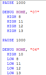
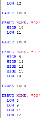
4 The diagram below will help determine which Boe-Bot pins to activate to form certain numbers. 2. Program the Boe-Bot to count down from 10 to 0 with one second intervals using HIGH:LOW commands. Remember that to turn on a segment, you must set the pin LOW, and to turn off a segment, set the pin HIGH. While writing the program, observe that some segments may already be on and only turn on or off the needed segments. Maintain the number zero in the first digit after the number 10; i.e. 10, 09, 08, 07 Teachers: You can decide how much of the following code to give to the students and how much to let them discover on their own. The homework assignment tonight and in-class activity tomorrow asks the students to create subroutines to display 0 9 on each of the displays, and then write a program to count down from The PBasic commands DIRH and DIRL work very well here, so feel free to get the students to look at them.
5
6
Digital To Analog Converter with Sine Wave Output
 Digital To Analog Converter with Sine Wave Output Overview In this Lab we will build a resistive ladder network and use the BASIC Stamp to generate the digital data for the D/A conversions. PBASIC will
Chapter 4: Pulse Width Modulation
 Pulse Width Modulation Page 127 Chapter 4: Pulse Width Modulation PULSES FOR COMMUNICATION AND CONTROL Pulse width modulation is abbreviated PWM, and it refers to a technique of varying the amount of time
ServoPAL (#28824): Servo Pulser and Timer
: Servo Pulser and Timer") Web Site: www.parallax.com Forums: forums.parallax.com Sales: sales@parallax.com Technical: support@parallax.com Office: (916) 624-8333 Fax: (916) 624-8003 Sales: (888) 512-1024 Tech Support: (888) 997-8267
Web Site: www.parallax.com Forums: forums.parallax.com Sales: sales@parallax.com Technical: support@parallax.com Office: (916) 624-8333 Fax: (916) 624-8003 Sales: (888) 512-1024 Tech Support: (888) 997-8267
Web Site: www.parallax.com Forums: forums.parallax.com Sales: sales@parallax.com Technical: support@parallax.com
 Web Site: www.parallax.com Forums: forums.parallax.com Sales: sales@parallax.com Technical: support@parallax.com Office: (916) 624-8333 Fax: (916) 624-8003 Sales: (888) 512-1024 Tech Support: (888) 997-8267
= (0.400 A) (4.80 V) = 1.92 W = (0.400 A) (7.20 V) = 2.88 W
 (4.80 V) = 1.92 W = (0.400 A) (7.20 V) = 2.88 W") Physics 2220 Module 06 Homework 0. What are the magnitude and direction of the current in the 8 Ω resister in the figure? Assume the current is moving clockwise. Then use Kirchhoff's second rule: 3.00
Physics 2220 Module 06 Homework 0. What are the magnitude and direction of the current in the 8 Ω resister in the figure? Assume the current is moving clockwise. Then use Kirchhoff's second rule: 3.00
SERVO CONNECTIONS FOR OLDER BOARDS
 What s a Microcontroller v3.0 Suppliment to Chapter 7, Activity #1 SERVO CONNECTIONS FOR OLDER BOARDS This document explains how to connect servo and LED indicator circuits to the older revisions of the
The Basics of Robot Mazes Teacher Notes
 The Basics of Robot Mazes Teacher Notes Why do robots solve Mazes? A maze is a simple environment with simple rules. Solving it is a task that beginners can do successfully while learning the essentials
PLL frequency synthesizer
 ANALOG & TELECOMMUNICATION ELECTRONICS LABORATORY EXERCISE 4 Lab 4: PLL frequency synthesizer 1.1 Goal The goals of this lab exercise are: - Verify the behavior of a and of a complete PLL - Find capture
Eric Mitchell April 2, 2012 Application Note: Control of a 180 Servo Motor with Arduino UNO Development Board
 Eric Mitchell April 2, 2012 Application Note: Control of a 180 Servo Motor with Arduino UNO Development Board Abstract This application note is a tutorial of how to use an Arduino UNO microcontroller to
Six-servo Robot Arm. DAGU Hi-Tech Electronic Co., LTD www.arexx.com.cn. Six-servo Robot Arm
 Six-servo Robot Arm 1 1, Introduction 1.1, Function Briefing Servo robot, as the name suggests, is the six servo motor-driven robot arm. Since the arm has a few joints, we can imagine, our human arm, in
Your Multimeter. The Arduino Uno 10/1/2012. Using Your Arduino, Breadboard and Multimeter. EAS 199A Fall 2012. Work in teams of two!
 Using Your Arduino, Breadboard and Multimeter Work in teams of two! EAS 199A Fall 2012 pincer clips good for working with breadboard wiring (push these onto probes) Your Multimeter probes leads Turn knob
Special Lecture. Basic Stamp 2 Programming. (Presented on popular demand)
") Special Lecture Basic Stamp 2 Programming (Presented on popular demand) Programming Environment Servo Motor: How It Work? The editor window consists of the main edit pane with an integrated explorer panel
Special Lecture Basic Stamp 2 Programming (Presented on popular demand) Programming Environment Servo Motor: How It Work? The editor window consists of the main edit pane with an integrated explorer panel
MIDECO 64-outputs MIDI note decoder USER MANUAL. Roman Sowa 2012
 MIDECO 64-outputs MIDI note decoder USER MANUAL Roman Sowa 2012 www.midi-hardware.com 1.Overview Thank you for choosing MIDECO as your new MIDI-to-digital converter. This short manual will guide you through
Downloading a Sample Program over USB
 Downloading a Sample Program over USB This document is a guide for downloading and running programs on the VEX Cortex using the USB A-to-A cable. You will need: 1 VEX Cortex Microcontroller with one 7.2V
STEPPER MOTOR SPEED AND POSITION CONTROL
 STEPPER MOTOR SPEED AND POSITION CONTROL Group 8: Subash Anigandla Hemanth Rachakonda Bala Subramanyam Yannam Sri Divya Krovvidi Instructor: Dr. Jens - Peter Kaps ECE 511 Microprocessors Fall Semester
USBSPYDER08 Discovery Kit for Freescale MC9RS08KA, MC9S08QD and MC9S08QG Microcontrollers User s Manual
 USBSPYDER08 Discovery Kit for Freescale MC9RS08KA, MC9S08QD and MC9S08QG Microcontrollers User s Manual Copyright 2007 SofTec Microsystems DC01197 We want your feedback! SofTec Microsystems is always on
Zeros, Ones, and the Morse Code
 Zeros, Ones, and the Morse Code Subject Area(s) Associated Unit Associated Lesson Activity Title Header Number & operations, science & technology None None Zeros, Ones, and the Morse Code Insert image
Bluetooth + USB 16 Servo Controller [RKI-1005 & RKI-1205]
![Bluetooth + USB 16 Servo Controller [RKI-1005 & RKI-1205]](/thumbs/40/21161302.jpg "Bluetooth + USB 16 Servo Controller [RKI-1005 & RKI-1205]") Bluetooth + USB 16 Servo Controller [RKI-1005 & RKI-1205] Users Manual Robokits India info@robokits.co.in http://www.robokitsworld.com Page 1 Bluetooth + USB 16 Servo Controller is used to control up to
Bluetooth + USB 16 Servo Controller [RKI-1005 & RKI-1205] Users Manual Robokits India info@robokits.co.in http://www.robokitsworld.com Page 1 Bluetooth + USB 16 Servo Controller is used to control up to
Whale 3. User Manual and Installation Guide. DC Servo drive. Contents. 1. Safety, policy and warranty. 1.1. Safety notes. 1.2. Policy. 1.3. Warranty.
 Whale 3 DC Servo drive User Manual and Installation Guide Contents 1. Safety, policy and warranty. 1.1. Safety notes. 1.2. Policy. 1.3. Warranty. 2. Electric specifications. 2.1.Operation ranges. 3. Connections
Servo Motors (SensorDAQ only) Evaluation copy. Vernier Digital Control Unit (DCU) LabQuest or LabPro power supply
 Evaluation copy. Vernier Digital Control Unit (DCU) LabQuest or LabPro power supply") Servo Motors (SensorDAQ only) Project 7 Servos are small, relatively inexpensive motors known for their ability to provide a large torque or turning force. They draw current proportional to the mechanical
Servo Motors (SensorDAQ only) Project 7 Servos are small, relatively inexpensive motors known for their ability to provide a large torque or turning force. They draw current proportional to the mechanical
Robotics with the Boe-Bot Student Guide
 Robotics with the Boe-Bot Student Guide VERSION 3.0 WARRANTY Parallax warrants its products against defects in materials and workmanship for a period of 90 days from receipt of product. If you discover
ECEN 1400, Introduction to Analog and Digital Electronics
 ECEN 1400, Introduction to Analog and Digital Electronics Lab 4: Power supply 1 INTRODUCTION This lab will span two lab periods. In this lab, you will create the power supply that transforms the AC wall
Massachusetts Institute of Technology Department of Electrical Engineering and Computer Science. 6.002 Electronic Circuits Spring 2007
 Massachusetts Institute of Technology Department of Electrical Engineering and Computer Science 6.002 Electronic Circuits Spring 2007 Lab 4: Audio Playback System Introduction In this lab, you will construct,
Reading assignment: All students should read the Appendix about using oscilloscopes.
 10. A ircuits* Objective: To learn how to analyze current and voltage relationships in alternating current (a.c.) circuits. You will use the method of phasors, or the vector addition of rotating vectors
ETEC 421 - Digital Controls PIC Lab 10 Pulse Width Modulation
 ETEC 421 - Digital Controls PIC Lab 10 Pulse Width Modulation Program Definition: Write a program to control the speed of a dc motor using pulse width modulation. Discussion: The speed of a dc motor is
Technical Aspects of Creating and Assessing a Learning Environment in Digital Electronics for High School Students
 Session: 2220 Technical Aspects of Creating and Assessing a Learning Environment in Digital Electronics for High School Students Adam S. El-Mansouri, Herbert L. Hess, Kevin M. Buck, Timothy Ewers Microelectronics
CHAPTER 11: Flip Flops
 CHAPTER 11: Flip Flops In this chapter, you will be building the part of the circuit that controls the command sequencing. The required circuit must operate the counter and the memory chip. When the teach
cs281: Introduction to Computer Systems Lab08 Interrupt Handling and Stepper Motor Controller
 cs281: Introduction to Computer Systems Lab08 Interrupt Handling and Stepper Motor Controller Overview The objective of this lab is to introduce ourselves to the Arduino interrupt capabilities and to use
MODULE BOUSSOLE ÉLECTRONIQUE CMPS03 Référence : 0660-3
 MODULE BOUSSOLE ÉLECTRONIQUE CMPS03 Référence : 0660-3 CMPS03 Magnetic Compass. Voltage : 5v only required Current : 20mA Typ. Resolution : 0.1 Degree Accuracy : 3-4 degrees approx. after calibration Output
Bidirectional wireless communication using EmbedRF
 Bidirectional wireless communication using EmbedRF 1. Tools you will need for this application note... 2 2. Introduction... 3 3. Connect EmbedRF Board to USB Interface Board... 3 4. Install and Run EmbedRF
Digital Electronics Detailed Outline
 Digital Electronics Detailed Outline Unit 1: Fundamentals of Analog and Digital Electronics (32 Total Days) Lesson 1.1: Foundations and the Board Game Counter (9 days) 1. Safety is an important concept
XBee USB Adapter Board (#32400)
") Web Site: www.parallax.com Forums: forums.parallax.com Sales: sales@parallax.com Technical: support@parallax.com Office: (916) 624-8333 Fax: (916) 624-8003 Sales: (888) 512-1024 Tech Support: (888) 997-8267
Web Site: www.parallax.com Forums: forums.parallax.com Sales: sales@parallax.com Technical: support@parallax.com Office: (916) 624-8333 Fax: (916) 624-8003 Sales: (888) 512-1024 Tech Support: (888) 997-8267
PHYS 2P32 Project: MIDI for Arduino/ 8 Note Keyboard
 PHYS 2P32 Project: MIDI for Arduino/ 8 Note Keyboard University April 13, 2016 About Arduino: The Board Variety of models of Arduino Board (I am using Arduino Uno) Microcontroller constructd similarly
Programming PIC Microcontrollers in PicBasic Pro Lesson 1 Cornerstone Electronics Technology and Robotics II
 Programming PIC Microcontrollers in PicBasic Pro Lesson 1 Cornerstone Electronics Technology and Robotics II Administration: o Prayer PicBasic Pro Programs Used in This Lesson: o General PicBasic Pro Program
Arduino Microcontroller Guide W. Durfee, University of Minnesota ver. oct-2011 Available on-line at www.me.umn.edu/courses/me2011/arduino/
 Arduino Microcontroller Guide W. Durfee, University of Minnesota ver. oct-2011 Available on-line at www.me.umn.edu/courses/me2011/arduino/ 1 Introduction 1.1 Overview The Arduino microcontroller is an
Series and Parallel Resistive Circuits
 Series and Parallel Resistive Circuits The configuration of circuit elements clearly affects the behaviour of a circuit. Resistors connected in series or in parallel are very common in a circuit and act
Fastastic Frequencies
 Fastastic Frequencies Subject Area(s) Associated Unit Associated Lesson Activity Title Header mathematics, physics Fantastic Frequencies Image 1 ADA Description: Students working with the Basic Stamp 2
Parallax Serial LCD 2 rows x 16 characters Non-backlit (#27976) 2 rows x 16 characters Backlit (#27977) 4 rows x 20 characters Backlit (#27979)
 2 rows x 16 characters Backlit (#27977) 4 rows x 20 characters Backlit (#27979)") 599 Menlo Drive, Suite 100 Rocklin, California 95765, USA Office: (916) 624-8333 Fax: (916) 624-8003 General: info@parallax.com Technical: support@parallax.com Web Site: www.parallax.com Educational: www.stampsinclass.com
599 Menlo Drive, Suite 100 Rocklin, California 95765, USA Office: (916) 624-8333 Fax: (916) 624-8003 General: info@parallax.com Technical: support@parallax.com Web Site: www.parallax.com Educational: www.stampsinclass.com
DS2438EVKIT+ Smart Battery Monitor Evaluation Kit
 19-4829; Rev 1; 8/09 www.maxim-ic.com DS2438EVKIT+ Smart Battery Monitor Evaluation Kit FEATURES Demonstrates the Capabilities of the DS2438 Smart Battery Monitor, Including: Temperature Measurement Voltage
OEM Manual MODEL 2350 ELECTRONIC DUAL CYLINDER SCALE
 OEM Manual MODEL 2350 ELECTRONIC DUAL CYLINDER SCALE Scaletron Industries, Ltd. Bedminster Industrial Park 53 Apple Tree Lane P.O. Box 365 Plumsteadville, PA 18949 USA Toll Free: 1-800-257-5911 (USA &
Gripper Kit for the Boe-Bot Robot (#28202)
") 599 Menlo Drive, Suite 100 Rocklin, California 95765, USA Office: (916) 624-8333 Fax: (916) 624-8003 General: info@parallax.com Technical: support@parallax.com Web Site: www.parallax.com Educational: www.stampsinclass.com
599 Menlo Drive, Suite 100 Rocklin, California 95765, USA Office: (916) 624-8333 Fax: (916) 624-8003 General: info@parallax.com Technical: support@parallax.com Web Site: www.parallax.com Educational: www.stampsinclass.com
Vehicle Monitoring Quick Reference Guide
 Vehicle Monitoring Quick Reference Guide Powered by Delphi Welcome You re about to experience a powerful device that will deliver a new level of convenience and peace of mind with your vehicle. When combined
Arduino Lesson 14. Servo Motors
 Arduino Lesson 14. Servo Motors Created by Simon Monk Last updated on 2013-06-11 08:16:06 PM EDT Guide Contents Guide Contents Overview Parts Part Qty The Breadboard Layout for 'Sweep' If the Servo Misbehaves
Arduino Lesson 13. DC Motors. Created by Simon Monk
 Arduino Lesson 13. DC Motors Created by Simon Monk Guide Contents Guide Contents Overview Parts Part Qty Breadboard Layout Arduino Code Transistors Other Things to Do 2 3 4 4 4 6 7 9 11 Adafruit Industries
Electronics. Discrete assembly of an operational amplifier as a transistor circuit. LD Physics Leaflets P4.2.1.1
 Electronics Operational Amplifier Internal design of an operational amplifier LD Physics Leaflets Discrete assembly of an operational amplifier as a transistor circuit P4.2.1.1 Objects of the experiment
MFRD52x. Mifare Contactless Smart Card Reader Reference Design. Document information
 Rev. 2.1 17. April 2007 Preliminary Data Sheet Document information Info Keywords Content MFRC522, MFRC523, MFRC52x, MFRD522, MFRD523, Mifare Contactless Smart Card Reader Reference Design, Mifare Reader
Experiment #5, Series and Parallel Circuits, Kirchhoff s Laws
 Physics 182 Summer 2013 Experiment #5 1 Experiment #5, Series and Parallel Circuits, Kirchhoff s Laws 1 Purpose Our purpose is to explore and validate Kirchhoff s laws as a way to better understanding
Basic Analog and Digital Student Guide
 Basic Analog and Digital Student Guide VERSION 1.4 WARRANTY Parallax, Inc. warrants its products against defects in materials and workmanship for a period of 90 days. If you discover a defect, Parallax
Chapter 5. Components, Symbols, and Circuitry of Air-Conditioning Wiring Diagrams
 Chapter 5 Components, Symbols, and Circuitry of Air-Conditioning Wiring Diagrams Objectives Upon completion of this course, you will be able to: Explain what electrical loads are and their general purpose
GPS INSTALLATION & USER GUIDE. Internet. Compatible with the following controllers. Nomad SD/SD2. ALL RIGHTS RESERVED Rev 03.25.11
 GPS INSTALLATION & USER GUIDE Compatible with the following controllers TV Nomad 3 Nomad SD/SD2 Internet MESA ALL RIGHTS RESERVED Rev 03.25.11 INDEX BILL OF MATERIALS Components for configuration 3 BLOCK
Conversion Between Analog and Digital Signals
 ELET 3156 DL - Laboratory #6 Conversion Between Analog and Digital Signals There is no pre-lab work required for this experiment. However, be sure to read through the assignment completely prior to starting
Lab #5: Design Example: Keypad Scanner and Encoder - Part 1 (120 pts)
") Dr. Greg Tumbush, gtumbush@uccs.edu Lab #5: Design Example: Keypad Scanner and Encoder - Part 1 (120 pts) Objective The objective of lab assignments 5 through 9 are to systematically design and implement
Dr. Greg Tumbush, gtumbush@uccs.edu Lab #5: Design Example: Keypad Scanner and Encoder - Part 1 (120 pts) Objective The objective of lab assignments 5 through 9 are to systematically design and implement
Fondamenti su strumenti di sviluppo per microcontrollori PIC
 Fondamenti su strumenti di sviluppo per microcontrollori PIC MPSIM ICE 2000 ICD 2 REAL ICE PICSTART Ad uso interno del corso Elettronica e Telecomunicazioni 1 2 MPLAB SIM /1 MPLAB SIM is a discrete-event
Excel 2003: Ringtones Task
 Excel 2003: Ringtones Task 1. Open up a blank spreadsheet 2. Save the spreadsheet to your area and call it Ringtones.xls 3. Add the data as shown here, making sure you keep to the cells as shown Make sure
ELEC 2210 - EXPERIMENT 1 Basic Digital Logic Circuits
 Objectives ELEC - EXPERIMENT Basic Digital Logic Circuits The experiments in this laboratory exercise will provide an introduction to digital electronic circuits. You will learn how to use the IDL-00 Bit
MODEL 5010 DUAL CHANNEL SMOKE/FIRE DETECTION MODULE
 DESCRIPTION MODEL 5010 DUAL CHANNEL SMOKE/FIRE DETECTION MODULE DESCRIPTION The SST Model 5010 Two Channel Smoke/Fire Detection Module provides two independent detection input channels for the NOVA-5000
Figure 8-1 Four Possible Results of Adding Two Bits
 CHPTER EIGHT Combinational Logic pplications Thus far, our discussion has focused on the theoretical design issues of computer systems. We have not yet addressed any of the actual hardware you might find
M68EVB908QL4 Development Board for Motorola MC68HC908QL4
 M68EVB908QL4 Development Board for Motorola MC68HC908QL4! Axiom Manufacturing 2813 Industrial Lane Garland, TX 75041 Email: Sales@axman.com Web: http://www.axman.com! CONTENTS CAUTIONARY NOTES...3 TERMINOLOGY...3
How to Move Canon EF Lenses. Yosuke Bando
 How to Move Canon EF Lenses Yosuke Bando Preface This instruction is intended to be helpful to those who are interested in making modifications to camera lenses to explore/reproduce focus sweep, focal
What s a Microcontroller? Student Guide
 What s a Microcontroller? Student Guide VERSION 3.0 Page 2 What s a Microcontroller? WARRANTY Parallax warrants its products against defects in materials and workmanship for a period of 90 days from receipt
EMBEDDED ACCESS CONTROL Hardware Installation Guide
 EMBEDDED ACCESS CONTROL Hardware Installation Guide Lenel goentry Hardware Installation Guide, product version 1.00. This guide is item number DOC- ENHW-ENU, revision 1.003, April 2009 Copyright 2009 Lenel
Robot Board Sub-System Testing. Abstract. Introduction and Theory. Equipment. Procedures. EE 101 Spring 2006 Date: Lab Section # Lab #6
 EE 101 Spring 2006 Date: Lab Section # Lab #6 Name: Robot Board Sub-System Testing Partner: No Lab partners this time! Abstract The ECEbot robots have a printed circuit board (PCB) containing most of the
Industrial Automation Training Academy. PLC, HMI & Drives Training Programs Duration: 6 Months (180 ~ 240 Hours)
") nfi Industrial Automation Training Academy Presents PLC, HMI & Drives Training Programs Duration: 6 Months (180 ~ 240 Hours) For: Electronics & Communication Engineering Electrical Engineering Instrumentation
nfi Industrial Automation Training Academy Presents PLC, HMI & Drives Training Programs Duration: 6 Months (180 ~ 240 Hours) For: Electronics & Communication Engineering Electrical Engineering Instrumentation
A Digital Timer Implementation using 7 Segment Displays
 A Digital Timer Implementation using 7 Segment Displays Group Members: Tiffany Sham u2548168 Michael Couchman u4111670 Simon Oseineks u2566139 Caitlyn Young u4233209 Subject: ENGN3227 - Analogue Electronics
PRODUCTIVITY THROUGH INNOVATION 600 CONTROL DIRECT DRIVE TECHNICAL/OPERATION MANUAL
 Rev. D PRODUCTIVITY THROUGH INNOVATION 600 CONTROL DIRECT DRIVE TECHNICAL/OPERATION MANUAL 10 BORIGHT AVENUE, KENILWORTH NEW JERSEY 07033 TELEPHONE: 800-524-0273 FAX: 908-686-9317 TABLE OF CONTENTS Page
Rethinking the First Year Programming Course
 Rethinking the First Year Programming Course William David Lubitz Assistant Professor, School of Engineering, University of Guelph wlubitz@uoguelph.ca Abstract The use of microcontrollers in beginning
BASIC Stamp Guide W. Durfee, University of Minnesota ver: oct-08 Available on-line at www.me.umn.edu/courses/me2011/robot/
 BASIC Stamp Guide W. Durfee, University of Minnesota ver: oct-08 Available on-line at www.me.umn.edu/courses/me2011/robot/ 1. Introduction Overview The BASIC Stamp is the simplest microcontroller to learn
Cornerstone Electronics Technology and Robotics I Week 15 Voltage Comparators Tutorial
 Cornerstone Electronics Technology and Robotics I Week 15 Voltage Comparators Tutorial Administration: o Prayer Robot Building for Beginners, Chapter 15, Voltage Comparators: o Review of Sandwich s Circuit:
ENGI E1112 Departmental Project Report: Computer Science/Computer Engineering
 ENGI E1112 Departmental Project Report: Computer Science/Computer Engineering Daniel Estrada Taylor, Dev Harrington, Sekou Harris December 2012 Abstract This document is the final report for ENGI E1112,
Access Control Using Smartcard And Passcode
 IOSR Journal of Electrical and Electronics Engineering (IOSR-JEEE) e-issn: 2278-1676 Volume 4, Issue 5 (Jan. - Feb. 2013), PP 29-34 Access Control Using Smartcard And Passcode Omorogiuwa Eseosa 1., Uhunmwangho
Measuring Electric Phenomena: the Ammeter and Voltmeter
 Measuring Electric Phenomena: the Ammeter and Voltmeter 1 Objectives 1. To understand the use and operation of the Ammeter and Voltmeter in a simple direct current circuit, and 2. To verify Ohm s Law for
Evaluation copy. Build a Temperature Sensor. Project PROJECT DESIGN REQUIREMENTS
 Build a emperature Sensor Project A sensor is a device that measures a physical quantity and converts it into an electrical signal. Some sensors measure physical properties directly, while other sensors
Having read this workbook you should be able to: recognise the arrangement of NAND gates used to form an S-R flip-flop.
 Objectives Having read this workbook you should be able to: recognise the arrangement of NAND gates used to form an S-R flip-flop. describe how such a flip-flop can be SET and RESET. describe the disadvantage
Lab 3 Microcontroller programming Interfacing to Sensors and Actuators with irobot
 1. Objective Lab 3 Microcontroller programming Interfacing to Sensors and Actuators with irobot In this lab, you will: i. Become familiar with the irobot and AVR tools. ii. Understand how to program a
Web Site: www.parallax.com Forums: forums.parallax.com Sales: sales@parallax.com Technical: support@parallax.com
 Web Site: www.parallax.com Forums: forums.parallax.com Sales: sales@parallax.com Technical: support@parallax.com Office: (916) 624-8333 Fax: (916) 624-8003 Sales: (888) 512-1024 Tech Support: (888) 997-8267
TPG MOBILE BROADBAND QUICK SETUP GUIDE
 TPG MOBILE BROADBAND QUICK SETUP GUIDE TPG USB E1762 Modem Thank you for choosing TPG Mobile Broadband and USB E1762 modem. This User Guide provides step by step instructions that will take you through
EET272 Worksheet Week 9
 EET272 Worksheet Week 9 answer questions 1-5 in preparation for discussion for the quiz on Monday. Finish the rest of the questions for discussion in class on Wednesday. Question 1 Questions AC s are becoming
Test Driven Development of Embedded Systems Using Existing Software Test Infrastructure
 Test Driven Development of Embedded Systems Using Existing Software Test Infrastructure Micah Dowty University of Colorado at Boulder micah@navi.cx March 26, 2004 Abstract Traditional software development
INTRODUCTION TO SERIAL ARM
 INTRODUCTION TO SERIAL ARM A robot manipulator consists of links connected by joints. The links of the manipulator can be considered to form a kinematic chain. The business end of the kinematic chain of
Controlling a Dot Matrix LED Display with a Microcontroller
 Controlling a Dot Matrix LED Display with a Microcontroller By Matt Stabile and programming will be explained in general terms as well to allow for adaptation to any comparable microcontroller or LED matrix.
Arduino Lab 1 - The Voltage Divider
 Arduino Lab 1 - The Voltage Divider 1. Introduction In this lab, we will endanger a cute animal, create a portal to another dimension, and invent a new genre of music. Along the way, we will learn about
Servo Info and Centering
 Info and Centering A servo is a mechanical motorized device that can be instructed to move the output shaft attached to a servo wheel or arm to a specified position. Inside the servo box is a DC motor
Ocean Controls RC Servo Motor Controller
 Ocean Controls RC Servo Motor Controller RC Servo Motors: RC Servo motors are used in radio-controlled model cars and planes, robotics, special effects, test equipment and industrial automation. At the
Automated Contact Resistance Tester CR-2601
 Automated Contact Resistance Tester CR-2601 What s New What s New Summary of Hardware Improvements: The middle Stiffener has been improved and no longer comes in direct contact with the main board thus
Chapter 02: Computer Organization. Lesson 04: Functional units and components in a computer organization Part 3 Bus Structures
 Chapter 02: Computer Organization Lesson 04: Functional units and components in a computer organization Part 3 Bus Structures Objective: Understand the IO Subsystem and Understand Bus Structures Understand
The components. E3: Digital electronics. Goals:
 E3: Digital electronics Goals: Basic understanding of logic circuits. Become familiar with the most common digital components and their use. Equipment: 1 st. LED bridge 1 st. 7-segment display. 2 st. IC
FREQUENCY RESPONSE OF AN AUDIO AMPLIFIER
 2014 Amplifier - 1 FREQUENCY RESPONSE OF AN AUDIO AMPLIFIER The objectives of this experiment are: To understand the concept of HI-FI audio equipment To generate a frequency response curve for an audio
Construction and Application of a Computer Based Interface Card
 Session 4 Construction and Application of a Computer Based Interface Card Michael Combs Telescope Operations Engineer m.combs@morehead-st.edu Morehead State University Morehead, Kentucky Ahmad Zargari,
Massachusetts Institute of Technology Department of Electrical Engineering and Computer Science 6.115 Microprocessor Project Laboratory
 Massachusetts Institute of Technology Department of Electrical Engineering and Computer Science 6.115 Microprocessor Project Laboratory Connecting your PSoC Evaluation Board It is easy and fun to avoid
Objectives 200 CHAPTER 4 RESISTANCE
 Objectives Explain the differences among conductors, insulators, and semiconductors. Define electrical resistance. Solve problems using resistance, voltage, and current. Describe a material that obeys
Mini Effect Gizmo. User s Manual. RJM Music Technology, Inc.
 Mini Effect Gizmo User s Manual RJM Music Technology, Inc. Mini Effect Gizmo User s Manual Version 1.3 September 26, 2013 RJM Music Technology, Inc. 2525 Pioneer Ave #1 Vista, CA 92081 E-mail: support@rjmmusic.com
Data Sheet. Adaptive Design ltd. Arduino Dual L6470 Stepper Motor Shield V1.0. 20 th November 2012. L6470 Stepper Motor Shield
 Arduino Dual L6470 Stepper Motor Shield Data Sheet Adaptive Design ltd V1.0 20 th November 2012 Adaptive Design ltd. Page 1 General Description The Arduino stepper motor shield is based on L6470 microstepping
TE100-P21/TEW-P21G Windows 7 Installation Instruction
 Hardware Installation TE100-P21/TEW-P21G Windows 7 Installation Instruction 1. Go to http://www.trendnet.com/downloads/ to download the Windows 7 Utility. Save the file to your desktop. 2. Right click
Electronics 5: Arduino, PWM, Mosfetts and Motors
 BIOE 123 Module 6 Electronics 5: Arduino, PWM, Mosfetts and Motors Lecture (30 min) Date Learning Goals Learn about pulse width modulation (PWM) as a control technique Learn how to use a Mosfets to control
EXPERIMENT 7 OHM S LAW, RESISTORS IN SERIES AND PARALLEL
 260 7- I. THEOY EXPEIMENT 7 OHM S LAW, ESISTOS IN SEIES AND PAALLEL The purposes of this experiment are to test Ohm's Law, to study resistors in series and parallel, and to learn the correct use of ammeters
5-Slot Housing and FrameSaver 9000 Series Access Carrier AC Power Supply Installation Instructions
 TM 5-Slot Housing and FrameSaver 9000 Series Access Carrier AC Power Supply Installation Instructions Document Number 9000-A2-GN17-30 August 1998 Before You Begin Both the 5-slot housing and the FrameSaver
Massachusetts Institute of Technology
 Objectives Massachusetts Institute of Technology Robotics: Science and Systems I Lab 1: System Overview and Introduction to the µorcboard Distributed: February 4, 2015, 3:30pm Checkoffs due: February 9,
Microcontroller Code Example Explanation and Words of Wisdom For Senior Design
 Microcontroller Code Example Explanation and Words of Wisdom For Senior Design For use with the following equipment: PIC16F877 QikStart Development Board ICD2 Debugger MPLAB Environment examplemain.c and
Accurate Measurement of the Mains Electricity Frequency
 Accurate Measurement of the Mains Electricity Frequency Dogan Ibrahim Near East University, Faculty of Engineering, Lefkosa, TRNC dogan@neu.edu.tr Abstract The frequency of the mains electricity supply
Basic voltmeter use. Resources and methods for learning about these subjects (list a few here, in preparation for your research):
:") Basic voltmeter use This worksheet and all related files are licensed under the Creative Commons ttribution License, version 1.0. To view a copy of this license, visit http://creativecommons.org/licenses/by/1.0/,
Basic voltmeter use This worksheet and all related files are licensed under the Creative Commons ttribution License, version 1.0. To view a copy of this license, visit http://creativecommons.org/licenses/by/1.0/,