Subdivision for Modeling and Animation
|
|
|
- Juliana Greer
- 8 years ago
- Views:
Transcription
1 SIGGRAPH 99 Course Notes Subdivision for Modeling and Animation Organizers: Denis Zorin, New York University Peter Schröder, California Institute of Technology

2

3 Lecturers Denis Zorin Media Research Laboratory 79 Broadway,rm. 20 New York University New York, NY 002 net: Peter Schröder Caltech Multi-Res Modeling Group Computer Science Department California Institute of Technology Pasadena, CA 925 net: Tony DeRose Studio Tools Group Pixar Animation Studios 00 West Cutting Blvd. Richmond, CA net: Jos Stam Member Technical Staff Aliasjwavefront 28 First Avenue, 8th Floor Seattle, WA 9804 net: Leif Kobbelt Computer Graphics Group Max-Planck-Institute for Computer Sciences Im Stadtwald 6623 Saarbrücken, Germany net: Joe Warren Computer Graphics and Geometric Design Group Computer Science Department Rice University Houston, Tx net:

4

5 Schedule Morning Session: Introductory Material The morning section will focus on the foundations of subdivision, starting with subdivision curves and moving on to surfaces. We will review and compare a number of different schemes and discuss the relation between subdivision and splines. The emphasis will be on properties of subdivsion most relevant for applications. Foundations I: Basic Ideas Peter Schröder and Denis Zorin Foundations II: Evaluation and survey of subdivision schemes Denis Zorin and Jos Stam Afternoon Session: Applications and Algorithms The afternoon session will focus on applications of subdivision and the algorithmic issues practitioners need to address to build efficient, well behaving systems for modeling and animation with subdivision surfaces. Implementing Subdivision and Multiresolution Meshes Denis Zorin A Variational Approach to Subdivision Leif Kobbelt Variational Subdivision Cookbook Joe Warren Subdivision Surfaces in the Making of Geri s Game Tony DeRose 5

6 6
7 Lecturers Biographies Denis Zorin is an assistant professor at the Courant Institute of Mathematical Sciences, New York University. He received a BS degree from the Moscow Institute of Physics and Technology, a MS degree in Mathematics from Ohio State University and a PhD in Computer Science from the California Institute of Technology. In , he was a research associate at the Computer Science Department of Stanford University. His research interests include multiresolution modeling, the theory of subdivision, and applications of subdivision surfaces in Computer Graphics. He is also interested in perceptually-based computer graphics algorithms. He has published several papers in Siggraph proceedings. Peter Schröder is an associate professor of computer science at the California Institute of Technology, Pasadena, where he directs the Caltech Multi-Res Modeling Group. He received a Master s degree from the MIT Media Lab and a PhD from Princeton University. For the past 6 years his work has concentrated on exploiting wavelets and multiresolution techniques to build efficient representations and algorithms for many fundamental computer graphics problems. His current research focuses on subdivision as a fundamental paradigm for geometric modeling and rapid manipulation of large, complex geometric models. The results of his work have been published in venues ranging from Siggraph to special journal issues on wavelets and WIRED magazine, and he is a frequent consultant to industry. Tony DeRose is currently a member of the Tools Group at Pixar Animation Studios. He received a BS in Physics in 98 from the University of California, Davis; in 985 he received a Ph.D. in Computer Science from the University of California, Berkeley. He received a Presidential Young Investigator award from the National Science Foundation in 989. In 995 he was selected as a finalist in the software category of the Discover Awards for Technical Innovation. From September 986 to December 995 Dr. DeRose was a Professor of Computer Science and Engineering at the University of Washington. From September 99 to August 992 he was on sabbatical leave at the Xerox Palo Alto Research Center and at Apple Computer. He has served on various technical program committees including SIGGRAPH, and from 988 through 994 was an associate editor of ACM Transactions on Graphics. His research has focused on mathematical methods for surface modeling, data fitting, and more recently, in the use of multiresolution techniques. Recent projects include object acquisition from laser range data and multiresolution/wavelet methods for high-performance computer graphics. 7

8 Leif Kobbelt is a senior researcher at the Max-Planck-Institute for computer sciences in Saarbrücken, Germany. His major research interests include multiresolution and free-form modeling as well as the efficient handling of polygonal mesh data. He received his habilitation degree from the University of Erlangen, Germany where he worked from 996 to 999. In 995/96 he spent one post-doc year at the University of Wisconsin, Madison. He received his master s (992) and Ph.D. (994) degrees from the University of Karlsruhe, Germany. During the last 7 years he did research in various fields of computer graphics and CAGD. Jos Stam is currently a member of technical staff at Aliasjwavefront. He received BS degrees in computer science and mathematics from the University of Geneva, Switzerland in 988 and 989, and he received a MS and a PhD in computer science both from the University of Toronto in 99 and 995, respectively. His research interests cover most areas of computer graphics: natural phenomena, rendering, animation and surface modeling. He has published papers at SIGGRAPH and elsewhere in all of these areas. Recently, his research has focused on the fundamentals of subdivision surfaces and their practical use in a commercial product. Stam is a leading expert in both the theory and application of subdivision surfaces. His work on evaluating subdivision surfaces presented at last years SIGGRAPH conference has been widely acclaimed as being a landmark paper in the area. Joe Warren is currently an Associate Professor in the Department of Computer Science at Rice University. He received his master s and Ph.D. degrees in 986 from Cornell University. His research interests focus on the relationship between computers, mathematics and geometry. During the course of his research career, he has made fundamental contributions to topics such as algebraic surfaces, rational surfaces, finite element mesh generation and subdivision. Currently, he is investigating the relationship between subdivision and systems of partial differential equations. 8
 and Ph.D. (994) degrees from the University of Karlsruhe, Germany. During the last 7 years he did research in various fields of computer graphics and CAGD.")
9 Contents Introduction 2 Foundations I: Basic Ideas 5 2. The Idea of Subdivision ReviewofSplines Piecewise Polynomial Curves Definition of B-Splines Refinability of B-splines RefinementforSplineCurves Subdivision for Spline Curves Subdivision as Repeated Refinement DiscreteConvolution Convergence of Subdivision Summary Analysis of Subdivision Invariant Neighborhoods EigenAnalysis Convergence of Subdivision Invariance under Affine Transformations Geometric Behavior of Repeated Subdivision Size of the Invariant Neighborhood Summary

10 3 Subdivision Surfaces Subdivision Surfaces: an Example Natural Parameterization of Subdivision Surfaces Subdivision Matrix Smoothness of Surfaces C -continuityandtangentplanecontinuity Analysis of Subdivision Surfaces C -continuity of Subdivision away from Extraordinary Vertices SmoothnessNearExtraordinaryVertices CharacteristicMap Piecewise-smooth surfaces and subdivision Subdivision Zoo Overview of Subdivision Schemes NotationandTerminology LoopScheme ModifiedButterflyScheme Catmull-Clark Scheme Kobbelt Scheme Doo-SabinandMidedgeSchemes Limitations of Stationary Subdivision Evaluation of Subdivision Surfaces 6 Implementing Subdivision and Multiresolution Meshes 7 Interpolatory Subdivision for Quad Meshes 8 A Variational Approach to Subdivision 9 Subdivision Cookbook 0 Subdivision Surfaces in the Making of Geri s Game 0

11 Chapter Introduction Twenty years ago the publication of the papers by Catmull and Clark [3] and Doo and Sabin [4] marked the beginning of subdivision for surface modeling. This year, another milestone occurred when subdivision hit the big screen in Pixar s short Geri s Game, for which Pixar received an Academy award for Best Animated Short Film. The basic ideas behind subdivision are very old indeed and can be traced as far back as the late 40s and early 50s when G. de Rham used corner cutting to describe smooth curves. It was only recently though that subdivision surfaces have found their way into wide application in computer graphics and computer assisted geometric design (CAGD). One reason for this development is the importance of multiresolution techniques to address the challenges of ever larger and more complex geometry: subdivision is intricately linked to multiresolution and traditional mathematical tools such as wavelets. Constructing surfaces through subdivision elegantly addresses many issues that computer graphics practitioners are confronted with Arbitrary Topology: Subdivision generalizes classical spline patch approaches to arbitrary topology. This implies that there is no need for trim curves or awkward constraint management between patches. Scalability: Because of its recursive structure, subdivision naturally accommodates level-of-detail rendering and adaptive approximation with error bounds. The result are algorithms which can make the best of limited hardware resources, such as those found on low end PCs. Uniformity of Representation: Much of traditional modeling uses either polygonal meshes or spline patches. Subdivision spans the spectrum between these two extremes. Surfaces can behave
.")
12 as if they are made of patches, or they can be treated as if consisting of many small polygons. Numerical Stability: The meshes produced by subdivision have many of the nice properties finite element solvers require. As a result subdivision representations are also highly suitable for many numerical simulation tasks which are of importance in engineering and computer animation settings. Code Simplicity: Last but not least the basic ideas behind subdivision are simple to implement and execute very efficiently. While some of the deeper mathematical analyses can get quite involved this is of little concern for the final implementation and runtime performance. In this course and its accompanying notes we hope to convince you, the reader, that in fact the above claims are true! The main focus or our notes will be on covering the basic principles behind subdivision; how subdivision rules are constructed; to indicate how their analysis is approached; and, most importantly, to address some of the practical issues in turning these ideas and techniques into real applications. The following 2 chapters will be devoted to understanding the basic principles. We begin with some examples in the curve, i.e., D setting. This simplifies the exposition considerably, but still allows us to introduce all the basic ideas which are equally applicable in the surface setting. Proceeding to the surface setting we cover a variety of different subdivision schemes and their properties. With these basics in place we proceed to the second, applications oriented part, covering algorithms and implementations addressing Interactive Multiresolution Mesh Editing: This section discusses many of the data structure and algorithmic issues which need to be addressed to realize high performance. The result is a system which allows for interactive, multiresolution editing of fairly complex geometry on PC class machines with little hardware graphics support. Subdivision Surfaces and Wavelets: This section shows how subdivision is the key element in generalizing the traditional wavelet machinery to arbitrary topology surfaces. The result are a class of algorithms which open up applications such as compression for subdivision surfaces, for example. A Variational Approach to Subdivision: Most subdivision methods are stationary, i.e., they use a fixed set of rules. They are generally designed to exhibit some order of differentiability. In practice it is often much more important to consider the fairness of the resulting surfaces. Variational subdivision incorporates fairness measures into the subdivision process. 2

13 Exploiting Subdivision in Modeling and Animation: One reason subdivision is becoming very popular is that it supports hierarchical editing and animation semantics. This was discovered originally in the traditional spline setup and lead to the development of hierarchical splines. From that technique it is only a small step to multiresolution modeling using subdivision. This section discusses some of the issues in controlling animation hierarchically. Subdivision Surfaces in the Making of Geri s Game: This section discusses how subdivision surfaces successfully address the needs of very high end production environments. in the process new techniques had to be developed which are detailed in this part of the notes. Beyond these Notes One of the reasons that subdivision is enjoying so much interest right now is that it is very easy to implement and very efficient. In fact it is used in many computer graphics courses at universities as a homework exercise. The mathematical theory behind it is very beautiful, but also very subtle and at times technical. We are not treating the mathematical details in these notes, which are primarily intended for the computer graphics practitioners. However, for those interested in the theory there are many pointers to the literature. These notes as well as other materials such as presentation slides, applets and snippets of code are available on the web at and all readers are encouraged to explore the online resources. A repository of additional information beyond this course is maintained at 3

14 4
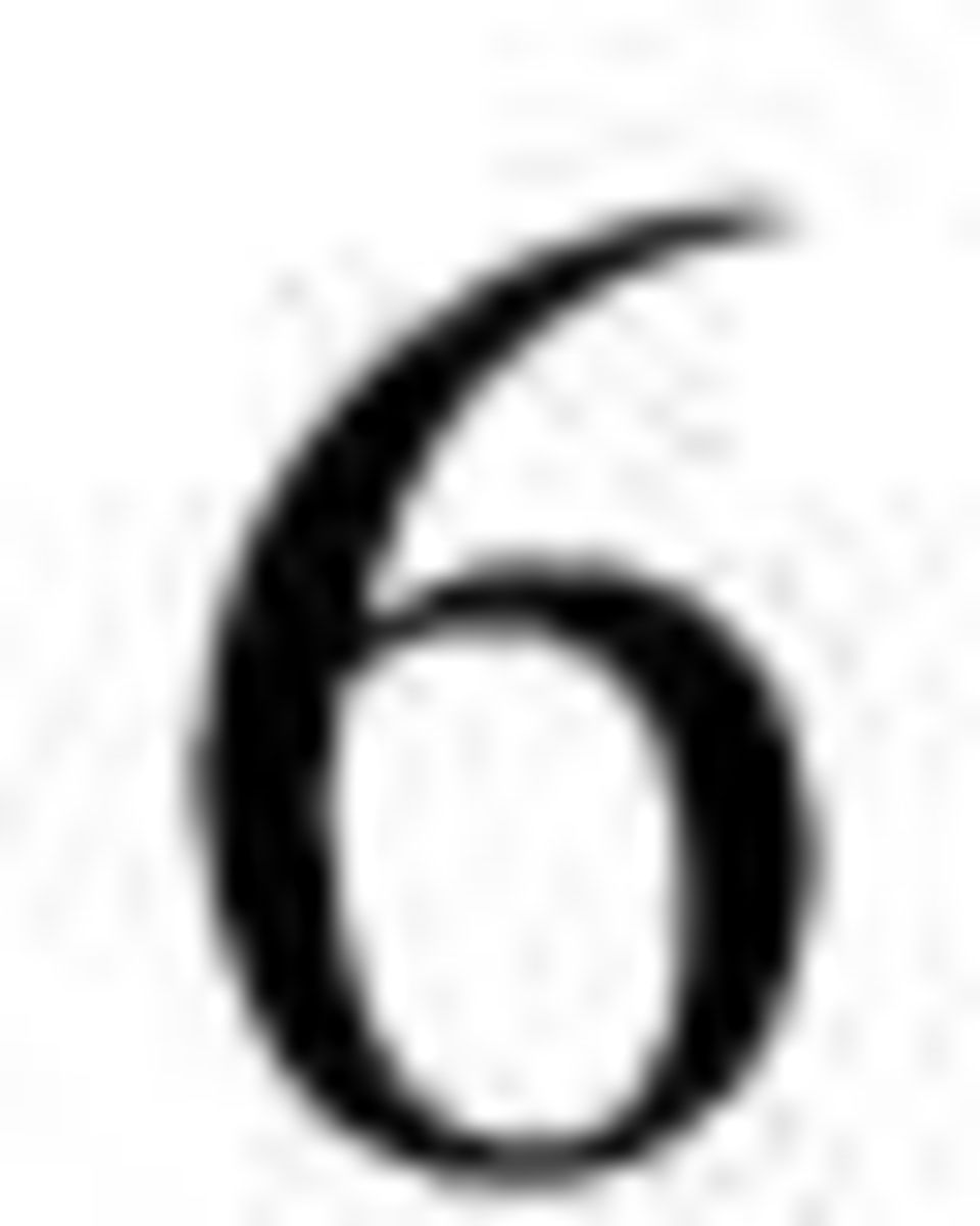
15 Chapter 2 Foundations I: Basic Ideas Peter Schröder, Caltech In this chapter we focus on the D case to introduce all the basic ideas and concepts before going on to the 2D setting. Examples will be used throughout to motivate these ideas and concepts. We begin initially with an example from interpolating subdivision, before talking about splines and their subdivision generalizations. Figure 2.: Example of subdivision for curves in the plane. On the left 4 points connected with straight line segments. To the right of it a refined version: 3 new points have been inserted inbetween the old points and again a piecewise linear curve connecting them is drawn. After two more steps of subdivision the curve starts to become rather smooth. 5

16 2. The Idea of Subdivision We can summarize the basic idea of subdivision as follows: Subdivision defines a smooth curve or surface as the limit of a sequence of successive refinements. Of course this is a rather loose description with many details as yet undetermined, but it captures the essence. Figure 2. shows an example in the case of a curve connecting some number of initial points in the plane. On the left we begin with 4 points connected through straight line segments. Next to it is a refined version. This time we have the original 4 points and additionally 3 more points inbetween the old points. Repeating the process we get a smoother looking piecewise linear curve. Repeating once more the curve starts to look quite nice already. It is easy to see that after a few more steps of this procedure the resulting curve would be as well resolved as one could hope when using finite resolution such as that offered by a computer monitor or a laser printer. Figure 2.2: Example of subdivision for a surface, showing 3 successive levels of refinement. On the left an initial triangular mesh approximating the surface. Each triangle is split into 4 according to a particular subdivision rule (middle). On the right the mesh is subdivided in this fashion once again. 6

17 An example of subdivision for surfaces is shown in Figure 2.2. In this case each triangle in the original mesh on the left is split into 4 new triangles quadrupling the number of triangles in the mesh. Applying the same subdivision rule once again gives the mesh on the right. Both of these examples show what is known as interpolating subdivision. The original points remain undisturbed while new points are inserted. We will see below that splines, which are generally not interpolating, can also be generated through subdivision. Albeit in that case new points are inserted and old points are moved in each step of subdivision. How were the new points determined? One could imagine many ways to decide where the new points should go. Clearly, the shape and smoothness of the resulting curve or surface depends on the chosen rule. Here we list a number of properties that we might look for in such rules: Efficiency: the location of new points should be computed with a small number of floating point operations; Compact support: the region over which a point influences the shape of the final curve or surface should be small and finite; Local definition: the rules used to determine where new points go should not depend on far away places; Affine invariance: if the original set of points is transformed, e.g., translated, scaled, or rotated, the resulting shape should undergo the same transformation; Simplicity: determining the rules themselves should preferably be an offline process and there should only be a small number of rules; Continuity: what kind of properties can we prove about the resulting curves and surfaces, for example, are they differentiable? For example, the rule used to construct the curve in Figure 2. computed new points by taking a weighted average of nearby old points: two to the left and two to the right with weights =6 (,;9;9;,) respectively (we are ignoring the boundaries for the moment). It is very efficient since it only involves 4 multiplies and 3 adds (per coordinate); has compact support since only 2 neighbors on either side are involved; its definition is local since the weights do not depend on anything in the arrangement of the points; the rule is affinely invariant since the weights used sum to ; it is very simple since only rule is used (there is one more rule if one wants to account for the boundaries); finally the limit curves one gets by repeating this process ad infinitum are C. 7

18 Before delving into the details of how these rules are derived we quickly compare subdivision to other possible modeling approaches for smooth surfaces: traditional splines, implicit surfaces, and variational surfaces.. Efficiency: Computational cost is an important aspect of a modeling method. Subdivision is easy to implement and is computationally efficient. Only a small number of neighboring old points are used in the computation of the new points. This is similar to knot insertion methods found in spline modeling, and in fact many subdivision methods are simply generalization of knot insertion. On the other hand implicit surfaces, for example, are much more costly. An algorithm such as marching cubes is required to generate the polygonal approximation needed for rendering. Variational surfaces can be even worse: a global optimization problem has to be solved each time the surface is changed. 2. Arbitrary topology: It is desirable to build surfaces of arbitrary topology. This is a great strength of implicit modeling methods. They can even deal with changing topology during a modeling session. Classic spline approaches on the other hand have great difficulty with control meshes of arbitrary topology. Here, arbitrary topology captures two properties. First, the topological genus of the mesh and associated surface can be arbitrary. Second, the structure of the graph formed by the edges and vertices of the mesh can be arbitrary; specifically, each vertex may be of arbitrary degree. These last two aspects are related: if we insist on all vertices having degree 4 (for quadrilateral) control meshes, or having degree 6 (for triangular) control meshes, the Euler characteristic for a planar graph tells us that such meshes can only be constructed if the overall topology of the shape is that of the infinite plane, the infinite cylinder, or the torus. Any other shape, for example a sphere, cannot be built from a quadrilateral (triangular) control mesh having vertices of degree 4 (6). When rectangular spline patches are used in arbitrary control meshes, enforcing higher order continuity at extraordinary vertices becomes difficult and considerably increases the complexity of the representation (see Figure 2.3 for an example of points not having valence 4). Implicit surfaces can be of arbitrary topological genus, but the genus, precise location, and connectivity of a surface are typically difficult to control. Variational surfaces can handle arbitrary topology better than any other representation, but the computational cost can be high. Subdivision can handle arbitrary topology quite well without losing efficiency; this is one of its key advantages. Historically subdivision arose when researchers were looking for ways to address the arbitrary topology modeling 8

19 Figure 2.3: A mesh with two extraordinary vertices, one with valence 6 the other with valence 3. In the case of quadrilateral patches the standard valence is 4. Special efforts are required to guarantee high order of continuity between spline patches meeting at the extraordinary points; subdivision handles such situations in a natural way. challenge for splines. 3. Surface features: Often it is desirable to control the shape and size of features, such as creases, grooves, or sharp edges. Variational surfaces provide the most flexibility and exact control for creating features. Implicit surfaces, on the other hand, are very difficult to control, since all modeling is performed indirectly and there is much potential for undesirable interactions between different parts of the surface. Spline surfaces allow very precise control, but it is computationally expensive and awkward to incorporate features, in particular if one wants to do so in arbitrary locations. Subdivision allows more flexible controls than is possible with splines. In addition to choosing locations of control points, one can manipulate the coefficients of subdivision to achieve effects such as sharp creases or control the behavior of the boundary curves. 4. Complex geometry: For interactive applications, efficiency is of paramount importance. Because subdivision is based on repeated refinement it is very straightforward to incorporate ideas such as level-of-detail rendering and compression for the internet. During interactive editing locally adaptive subdivision can generate just enough refinement based on geometric criteria, for example. 9

20 For applications that only require the visualization of fixed geometry, other representations, such as progressive meshes, are likely to be more suitable. Since most subdivision techniques used today are based upon and generalize splines we begin with a quick review of some basic facts of splines which we will need to understand the connection between splines and subdivision. 2.2 Review of Splines 2.2. Piecewise Polynomial Curves Splines are piecewise polynomial curves of some chosen degree. In the case of cubic splines, for example, each polynomial segment of the curve can be written as x(t) = a i 3 t3 + a i 2 t2 + a i t + ai 0 y(t) = b i 3t 3 + b i 2t 2 + b i t + b i 0 ; where (a; b) are constant coefficients which control the shape of the curve over the associated segment. This representation uses monomials (t 3 ;t 2 ;t ;t 0 ), which are restricted to the given segment, as basis functions Figure 2.4: Graph of the cubic B-spline. It is zero for the independent parameter outside the interval [,2;2]. Typically one wants the curve to have some order of continuity along its entire length. In the case of cubic splines one would typically want C 2 continuity. This places constraints on the coefficients (a;b) of neighboring curve segments. Manipulating the shape of the desired curves through these coefficients, 20
 = a i 3 t3 + a i 2 t2 + a i t + ai 0 y(t) = b i 3t 3 + b i 2t 2 + b i t + b i 0 ; where (a; b)")
21 while maintaining the constraints, is very awkward and difficult. Instead of using monomials as the basic building blocks, we can write the spline curve as a linear combination of shifted B-splines, each with a coefficient known as a control point x(t) = x i B(t, i) y(t) = y i B(t, i): The new basis function B(t) is chosen in such a way that the resulting curves are always continuous and that the influence of a control point is local. One way to ensure higher order continuity is to use basis functions which are differentiable of the appropriate order. Since polynomials themselves are inifinitely smooth, we only have to make sure that derivatives match at the points where two polynomial segments meet. The higher the degree of the polynomial, the more derivatives we are able to match. We also want the influence of a control point to be maximal over a region of the curve which is close to the control point. Its influence should decrease as we move away along the curve and disappear entirely at some distance. Finally, we want the basis functions to be piecewise polynomial so that we can represent any piecewise polynomial curve of a given degree with the associated basis functions. B-splines are constructed to exactly satisfy these requirements (for a cubic B-spline see Figure 2.4) and in a moment we will show how they are constructed. The advantage of using this representation rather than the earlier one of monomials, is that the continuity conditions at the segment boundaries are already hardwired into the basis functions. No matter how we move the control points, the spline curve will always maintain its continuity, for example, C 2 in the case of cubic B-splines. Furthermore, moving a control point has the greatest effect on the part of the curve near that control point, and no effect whatsoever beyond a certain range. These features make B-splines a much more appropriate tool for modeling piecewise polynomial curves. Note: When we talk about curves, it is important to distinguish the curve itself and the graphs of the coordinate functions of the curve, which can also be thought of as curves. For example, a curve can be described by equations x(t) =sin(t), y(t) =cos(t). The curve itself is a circle, but the coordinate functions are sinusoids. For the moment, we are going to concentrate on representing the coordinate functions. The differentiability of the basis functions guarantees the differentiability of the coordinate functions of the curve. However, it does not guarantee the geometric smoothness of the curve. We will return to this distinction in our discussion of subdivision surfaces. 2
22 2.2.2 Definition of B-Splines There are many ways to derive B-splines. Here we choose repeated convolution, since we can see from it directly how splines can be generated through subdivision. We start with the simplest case: piecewise constant coordinate functions. Any piecewise constant function can be written as where B 0 (t) is the box function defined as x(t) = x i B i 0 (t); B 0 (t) = if 0 t < = 0 otherwise; and the functions B i 0 (t) =B 0(t, i) are translates of B 0 (t). Furthermore, let us represent the continuous convolution of two functions f (t)and g(t) with ( f g)(t) = Z f (s)g(t, s)ds: A B-spline basis function of degree n can be obtained by convolving the basis function of degree n, with the box B 0 (t). 2 For example, the B-spline of degree is defined as the convolution of B 0 (t) with itself Z B (t) = B 0 (s)b 0 (t, s)ds: Graphically (see Figure 2.5), this convolution can be evaluated by sliding one box function along the coordinate axis from minus to plus infinity while keeping the second box fixed. The value of the convolution for a given position of the moving box is the area under the product of the boxes, which is just the length of the interval where both boxes are non-zero. At first the two boxes do not have common support. Once the moving box reaches 0, there is a growing overlap between the supports of the graphs. The value of the convolution grows with t until t =. Then the overlap starts decreasing, and the value of the convolution decreases down to zero at t = 2. The function B (t) is the linear hat function as shown in Figure 2.5. We can compute the B-spline of degree 2 convolving B (t) with the box B 0 (t) again B 2 (t) = Z B (s)b 0 (t, s)ds: 2 The degree of a polynomial is the highest order exponent which occurs, while the order counts the number of coefficients and is larger. For example, a cubic curve is of degree 3 and order 4. 22
23 Figure 2.5: The definition of degree B-Spline B (t) (right side) through convolution of B 0 (t) with itself (left side). In this case, the resulting curve consists of three quadratic segments defined on intervals (0; ), (; 2) and (2;3). In general, by convolving l times, we can get a B-spline of degree l B l (t) = Z B l, (s)b 0 (t, s)ds: Defining B-splines in this way a number of important properties immediately follow. The first concerns the continuity of splines Theorem If f (t) is C k -continuous, then (B 0 f )(t) is C k+ -continuous. 23
24 This is a direct consequence of convolution with a box function. From this it follows that the B-spline of degree n is C n, continuous because the B-spline of degree is C 0 -continuous Refinability of B-splines Another remarkable property of B-splines is that they obey a refinement equation. This is the key observation to connect splines and subdivision. The refinement equation for B-splines of degree l is given by B l+ l + l (t) = 2 l B l (2t, k): (2.) k k=0 In other words, the B-spline of degree l can be written as a linear combination of translated (k) and dilated (2t) copies of itself. For a function to be refineable in this way is a rather special property. As an example of the above equation at work consider the hat function shown in Figure 2.5. It is easy to see that it can be written as a linear combination of dilated hat functions with weights (=2;;=2) respectively. The property of refinability is the key to subdivision and so we will take a moment to prove it. We start by observing that the box function, i.e., the B-spline of degree 0 can be written in terms of dilates and translates of itself B 0 (t) =B 0 (2t)+B 0 (2t, ); (2.2) which is easily checked by direct inspection. Recall that we defined the B-spline of degree l as lo lo B l (t) = B 0 (t) = i=0 i=0 (B 0 (2t)+B 0 (2t, )) (2.3) This expression can be multiplied out by using the following properties of convolution for functions f (t), g(t), andh(t) f (t) (g(t)+h(t)) = f (t) g(t)+ f (t) h(t) linearity f (t, i) g(t, k) = m(t, i, k) time shift f (2t) g(2t) = 2m(2t) time scaling where m(t) = f (t) g(t). These properties are easy to check by substituting the definition of convolution and amount to simple change of variables in the integration. 24
25 For example, in the case of B we get B (t) = B 0 (t) B 0 (t) = (B 0 (2t)+B 0 (2t, )) (B 0 (2t)+B 0 (2t, )) = B 0 (2t) B 0 (2t)+B 0 (2t) B 0 (2t, )+B 0 (2t, ) B 0 (2t)+B 0 (2t, ) B 0 (2t, ) = 2 B (2t)+ 2 B (2t, )+ 2 B (2t, )+ 2 B (2t,, ) = 2 (B (2t)+2B (2t, )+B (2t, 2)) = 2 2 k=0 2 B (2t, k): k The general statement for B-splines of degree l now follows from the binomial theorem (x + y) l+ l+ l + = x l+,k y k ; k k=0 with B 0 (2t) in place of x and B 0 (2t, ) in place of y Refinement for Spline Curves With this machinery in hand let s revisit spline curves. Let " # x(t) γ(t) = = y(t) i p i B i l (t) be such a spline curve of degree l with control points (x i ;y i ) T = p i 2 R 2. Since we don t want to worry about boundaries for now we leave the index set i unspecified. We will also drop the subscript l since the degree, whatever it might be, is fixed for all our examples. Due to the definition of B i (t) =B(t, i) each control point exerts influence over a small part of the curve with parameter values t 2 [i; i + l]. Now consider p, the vector of control points of a given curve: 2 3. p,2 p, p = p 0 p 6 4 p
26 and the vector B(t), which has as its elements the translates of the function B as defined above h i B(t) = ::: B(t + 2) B(t + ) B(t) B(t, ) B(t, 2) ::: : In this notation we can denote our curve as B(t)p. Using the refinement relation derived earlier, we can rewrite each of the elements of B in terms of its dilates h i B(2t) = ::: B(2t + 2) B(2t + ) B(2t) B(2t, ) B(2t, 2) ::: ; using a matrix S to encode the refinement equations B(t) =B(2t)S: The entries of S are given by Equation 2. S 2i+k;i = s l + k = 2 l k The only non-zero entries in each column are the weights of the refinement equation, while successive columns are copies of one another save for a shift down by two rows. We can use this relation to rewrite γ(t) γ(t) = B(t)p = B(2t)Sp: It is still the same curve, but desribed with respect to dilated B-splines, i.e., B-splines whose support is half as wide and which are spaced twice as dense. We performed a change from the old basis B(t) to the new basis B(2t) and concurrently changed the old control points p to the appropriate new control points Sp. This process can be repeated γ(t) = B(t)p 0 = B(2t)p = B(2t)Sp 0. = B(2 j t)p j = B(2 j t)s j p 0 ; from which we can define the relationship between control points at different levels of subdivision where S is our infinite subdivision matrix. p j+ = Sp j ; 26 :
27 Looking more closely at one component, i, of our control points we see that p j+ i = l S i;l p j l : To find out exactly which s k is affecting which term, we can divide the above into odd and even entries. For the odd entries we have and for the even entries we have p j+ 2i+ = l S 2i+;l p j l = l s 2(i,l)+ p j l p j+ 2i = l S 2i;l p j l = l s 2(i,l) p j l : From which we essentially get two different subdivision rules one for the new even control points of the curve and one for the new odd control points. As examples of the above, let us consider two concrete cases. For piecewise linear subdivision, the basis functions are hat functions. The odd coefficients are 2 and 2, and a lone for the even point. For cubic splines the odd coefficients turn out to be 2 and 2, while the even coefficients are 8, 6 8,and 8. Another way to look at the distinction between even and odd is to notice that odd points at level j + are newly inserted, while even points at level j + correspond directly to the old points from level j. In the case of linear splines the even points are in fact the same at level j + astheywereatlevel j. Subdivision schemes that have this property will later be called interpolating, since points, once they have been computed, will never move again. In contrast to this consider cubic splines. In that case even points at level j + are local averages of points at level j so that p j+ 2i 6= p j i. Schemes of this type will later be called approximating Subdivision for Spline Curves In the previous section we saw that we can refine the control point sequence for a given spline by multiplying the control point vector p by the matrix S, which encodes the refinement equation for the B-spline used in the definition of the curve. What happens if we keep repeating this process over and over, generating ever denser sets of control points? It turns out the control point sequence converges to the actual spline curve. The speed of convergence is geometric, which is to say that the difference between the curve and its control points decreases by a constant factor on every subdivision step. Loosely speaking this means that the actual curve is hard to distinguish from the sequence of control points after only a few subdivision steps. 27
28 We can turn this last observation into an algorithm and the core of the subdivision paradigm. Instead of drawing the curve itself on the screen we draw the control polygon, i.e., the piecewise linear curve through the control points. Applying the subdivision matrix to the control points defines a sequence of piecewise linear curves which quickly converge to the spline curve itself. In order to make these observations more precise we need to introduce a little more machinery in the next section. 2.3 Subdivision as Repeated Refinement 2.3. Discrete Convolution The coefficients s k of the B-spline refinement equation can also be derived from another perspective, namely discrete convolution. This approach mimics closely the definition of B-splines through continuous convolution. Using this machinery we can derive and check many useful properties of subdivision by looking at simple polynomials. Recall that the generating function of a sequence a k is defined as A(z) = k a k z k ; where A(z) is the z-transform of the sequence a k. This representation is closely related to the discrete Fourier transform of a sequence by restricting the argument z to the unit circle, z = exp(iθ). For the case of two coefficient sequences a k and b k their convolution is defined as c k =(a b) k = n a k,n b n : In terms of generating functions this can be stated succinctly as C(z) =A(z)B(z); which comes as no surprise since convolution in the time domain is multiplication in the Fourier domain. The main advantage of generating functions, and the reason why we use them here, is that manipulations of sequences can be turned into simple operations on the generating functions. A very useful example of this is the next observation. Suppose we have two functions that each satisfy a refinement equation f (t) = k a k f (2t, k) g(t) = k b k g(2t, k): 28
29 In that case the convolution h = f g of f and g also satisfies a refinement equation h(t) = k c k h(2t, k); whose coefficients c k are given by the convolution of the coefficients of the individual refinement equations c k = 2 i a k,i b i : With this little observation we can quickly find the refinement equation, and thus the coefficients of the subdivision matrix S, by repeated multiplication of generating functions. Recall that the box function B 0 (t) satisfies the refinement equation B 0 (t) =B 0 (2t) +B 0 (2t, ). The generating function of this refinement equation is A(z) =( + z) since the only non-zero terms of the refinement equation are those belonging to indices 0 and. Now recall the definition of B-splines of degree l B l (t) = lo k=0 B 0 (t); from which we immediately get the associated generating function S(z) = 2 l ( + z)l+ : The values s k used for the definition of the subdivision matrix are simply the coefficients of the various powers of z in the polynomial S(z) S(z) = 2 l l+ k=0 l + k where we used the binomial theorem to expand S(z). Note how this matches the definition of s k in Equation 2.. Recall Theorem, which we used to argue that B-splines of degree n are C n, continuous. That same theorem can now be expressed in terms of generating functions as follows Theorem 2 If S(z) defines a convergent subdivision scheme yielding a C k -continuous limit function then 2 ( + z)s(z) defines a convergent subdivision scheme with Ck+ -continuous limit functions. We will put this theorem to work in analyzing a given subdivision scheme by peeling off as many factors of 2 ( + z) as possible, while still being able to prove that the remainder converges to a continuous 29 z k ;
30 limit function. With this trick in hand all we have left to do is establish criteria for the convergence of a subdivision scheme to a continuous function. Once we can verify such a condition for the subdivision scheme associated with B-spline control points we will be justified in drawing the piecewise linear approximations of control polygons as approximations for the spline curve itself. We now turn to this task Convergence of Subdivision There are many ways to talk about the convergence of a sequence of functions to a limit. One can use different norms and different notions of convergence. For our purposes the simplest form will suffice, uniform convergence. We say that a sequence of functions f i defined on some interval [a;b] R converges uniformly to a limit function f if for all ε > 0 there exists an n 0 > 0 such that for all n > n 0 max j f (t), f n (t)j < ε: t2[a;b] Or in words, as of a certain index (n 0 ) all functions in the sequence live within an ε sized tube around the limit function f. This form of convergence is sufficient for our purposes and it has the nice property that if a sequence of continuous functions converges uniformly to some limit function f, that limit function is itself continuous. For later use we introduce some norm symbols k f (t)k = supj f (t)j t jp i j kpk = sup i ksk = sup i js ik j; k which are compatible in the sense that, for example, kspkkskkpk. The sequence of functions we want to analyze now are the control polygons as we refine them with the subdivision rule S. Recall that the control polygon is the piecewise linear curve through the control points p j at level j. Independent of the subdivision rule S we can use the linear B-splines to define the piecewise linear curve through the control points as P j (t) =B (2 j t)p j. One way to show that a given subdivision scheme S converges to a continuous limit function is to prove that () the limit P (t) =lim j! P j (t) 30
31 exists for all t and (2) that the sequence P j (t) converges uniformly. In order to show this property we need to make the assumption that all rows of the matrix S sum to, i.e., the odd and even coefficients of the refinement relation separately sum to. This is a reasonable requirement since it is needed to ensure the affine invariance of the subdivision process, as we will later see. In matrix notation this means S =, or in other words, the vector of all s is an eigenvector of the subdivision matrix with eigenvalue. In terms of generating functions this means S(,) =0, which is easily verified for the generating functions we have seen so far. Recall that the definition of continuity in the function setting is based on differences. We say f (t) is continuous at t 0 if for any ε > 0 there exists a δ > 0sothatj f (t 0 ), f (t)j < ε as long as jt 0, tj < δ. The corresponding tool in the subdivision setting is the difference between two adjacent control points p j i+, p j i =( p j ) i. We will show that if the differences between neighboring control points shrink fast enough, the limit curve will exist and be continuous: Lemma 3 If k p j k < cγ j for some constant c > 0 and a shrinkage factor 0 < γ < for all j > j 0 0 then P j (t) converges to a continuous limit function P (t). Proof: Let S be the subdivision rule at hand, p = Sp 0 and S be the subdivision rule for B-splines of degree. Notice that the rows of S, S sum to 0 (S, S ) = S, S =, = 0: This implies that there exists a matrix D such that S, S = D, where computes the difference of adjacent elements ( ) ii =,, ( ) i;i+ =, and zero otherwise. The entries of D are given as D ij =, j k=i (S, S ) ik. Now consider the difference between two successive piecewise linear approximations of the control points kp j+ (t), P j (t)k = kb (2 j+ t)p j+, B (2 j t)p j k = kb (2 j+ t)sp j, B (2 j+ t)s p j k = kb (2 j+ t)(s, S )p j k kb (2 j+ t)kkd p j k kdkk p j k kdkcγ j : This implies that the telescoping sum P 0 (t)+ j k=0 (Pk+,P k )(t) converges to a well defined limit function since the norms of each summand are bounded by a constant times a geometric term γ j.letp (t) 3
32 as j!,then kp (t), P j (t)k < kdkc, γ γ j ; since the latter is the tail of a geometric series. This implies uniform convergence and thus continuity of P (t) as claimed. How do we check such a condition for a given subdivision scheme? Suppose we had a derived subdivision scheme D for the differences themselves defined as the scheme that satisfies p j+ = D p j ; S = D : Or in words, we are looking for a difference scheme D such that taking differences after subdivision is the same as applying the difference scheme to the differences. Does D always exist? The answer is yes if S is affinely invariant, i.e., S(,) =0. This follows from the following argument. Multiplying S by computes a matrix whose rows are differences of adjacent rows in S. Since odd and even numbered rows of S each sum to one, the rows of S must each sum to zero. Now the existence of a matrix D such that S = D follows as in the argument above. Given this difference scheme D all we would have to show is that some power m > 0ofD has norm less than, kd m k = γ <. In that case k p j k < c(γ =m ) j. (We will see in a moment that the extra degree of freedom provided by the parameter m is needed in some cases.) As an example, let us check this condition for cubic B-splines. Recall that B 3 (z) = 8 ( + z)4, i.e., Taking differences we have p j+ 2i+ = 8 (4p j i + 4p j i+ ) p j+ 2i = 8 (p j i, + 6p j i + p j i+ ): ( p j+ ) 2i = p j+ 2i+, p j+ 2i = 8 (,p j i,, 2p j i + 3p j i+ ) = 8 (3(p j i+, p j i )+(p j i, p j i, )) = 8 (3( p j ) i + ( p j ) i, ); and similarly for the odd entries so that D(z)= 8 (+z)3, from which we conclude that kdk = 2,andthat the subdivision scheme for cubic B-splines converges uniformly to a continuous limit function, namely the B-spline itself. 32
33 Another example, which is not a spline, is the so called 4 point scheme [5]. It was used to create the curve in Figure 2., which is interpolating rather than approximating as is the case with splines. The generating function for the 4 point scheme is S(z) = 6 (,z,3 + 4z,2, z, )( + z) 4 Recall that each additional factor of 2 (+z) in the generating function increases the order of continuity of the subdivision scheme. If we want to show that the limit function of the 4 point scheme is differentiable we need to show that 8 (,z,3 + 4z,2, z, )( + z) 3 converges to a continuous limit function. This in turn requires that D(z) = 8 (,z,3 +4z,2,z, )( +z) 2 satisfy a norm estimate as before. The rows of D have non-zero entries of ( 4 ;, 4 ),and( 8 ; 6 8 ;, 8 ) respectively. Thus kdk =, which is not strong enough. However, with a little bit more work one can show that kd 2 k = 3 4, so that indeed the 4 point scheme is C. In general, the difficult part is to find a set of coefficients for which subdivision converges. There is no general method to achieve this. Once a convergent subdivision scheme is found, one can always obtain a desired order of continuity by convolving with the box function Summary So far we have considered subdivision only in the context of splines where the subdivision rule, i.e., the coefficients used to compute a refined set of control points, was fixed and everywhere the same. There is no pressing reason for this to be so. We can create a variety of different curves by manipulating the coefficients of the subdivision matrix. This could be done globally or locally. I.e., we could change the coefficients within a subdivision level and/or between subdivision levels. In this regard, splines are just a special case of the more general class of curves, subdivision curves. For example, at the beginning of this chapter we briefly outlined an interpolating subdivision method, while spline based subdivision is approximating rather than interpolating. Why would one want to draw a spline curve by means of subdivision? In fact there is no sufficiently strong reason for using subdivision in one dimension and none of the commercial line drawing packages do so, but the argument becomes much more compelling in higher dimensions as we will see in later chapters. In the next section we use the subdivision matrix to study the behavior of the resulting curve at a point or in the neighborhood of a point. We will see that it is quite easy, for example, to evaluate the curve exactly at a point, or to compute a tangent vector, simply from a deeper understanding of the subdivision matrix. 33
34 2.4 Analysis of Subdivision In the previous section we have shown that uniform spline curves can be thought of as a special case of subdivision curves. So far, we have seen only examples for which we use a fixed set of coefficients to compute the control points everywhere. The coefficients define the appearance of the curve, for example, whether it is differentiable or has sharp corners. Consequently it is possible to control the appearance of the curve by modifying the subdivision coefficients locally. So far we have not seen a compelling reason to do so in the D setting. However, in the surface setting it will be essential to change the subdivision rule locally around extraordinary vertices to ensure maximal order of continuity. But before studying this question we once again look at the curve setting first since the treatment is considerably easier to follow in that setting. To study properties such as differentiability of the curve (or surface) we need to understand which of the control points influences the neighborhood of the point of interest. This notion is captured by the concept of invariant neighborhoods to which we turn now Invariant Neighborhoods Suppose we want to study the limit curve of a given subdivision scheme in the vicinity of a particular control point. 3 To determine local properties of a subdivision curve, we do not need the whole infinite vector of control points or the infinite matrix describing subdivision of the entire curve. Differentiability, for example, is a local property of a curve. To study it we need consider only an arbitrarily small piece of the curve around the origin. This leads to the question of which control points influence the curve in the neighborhood of the origin? As a first example consider cubic B-spline subdivision. There is one cubic segment to the left of the origin with parameter values t 2 [,;0] and one segment to the right with parameter range t 2 [0;]. Figure 2.6 illustrates that we need 5 control points at the coarsest level to reach any point of the limit curve which is associated with a parameter value between, and, no matter how close it is to the origin. We say that the invariant neighborhood has size 5. This size depends on the number of non-zero entries in each row of the subdivision matrix, which is 2 for odd points and 3 for even points. The latter implies that we need one extra control point to the left of, and one to the right of. Another way to see this argument is to consider the basis functions associated with a given subdivision scheme. Once those are found we can find all basis functions overlapping a region of interest and 3 Here and in the following we assume that the point of interest is the origin. This can always be achieved through renumbering of the control points. 34
35 Figure 2.6: In the case of cubic B-spline subdivision the invariant neighborhood is of size 5. It takes 5 control points at the coarsest level to determine the behavior of the subdivision limit curve over the two segments adjacent to the origin. At each level we need one more control point on the outside of the interval t 2 [,;] in order to continue on to the next subdivision level. 3 initial control points for example would not be enough. their control points will give us the control set for that region. How do we find these basis functions in the setting when we don t neccessarily produce B-splines through subdivision? The argument is 35
36 straightforward and also applies to surfaces. Recall that the subdivision operator is linear, i.e., P j (t) = B (2 j t)s j p 0! = B (2 j t)s j p 0 i (e i) 0 i = i p 0 i B (2 j t)s j (e i ) 0 = i p 0 i ϕ j i (t) In this expression e 0 i stands for the vector consisting of all 0s except a single in position i. In other words the final curve is always a linear combination with weights p 0 i of fundamental solutions lim ϕ j j! i (t) =ϕ i(t): If we used the same subdivision weights throughout the domain it is easy to see that ϕ i (t) =ϕ(t, i), i.e., there is a single function ϕ(t) such that all curves produced through subdivision from some initial sequence of points p 0 are linear combinations of translates of ϕ(t). This function is called the fundamental solution of the subdivision scheme. Questions such as differentiability of the limit curve can now be studied by examining this one function ϕ(t) =lim j! S j (e 0 ) 0 : For example, we can read off from the support of this function how far the influence of a control point will be felt. Similarly, the shape of this function tells us something about how the curve (or surface) will change when we pull on a control point. Note that in the surface case the rules we apply will depend on the valence of the vertex in question. In that case we won t get only a single fundamental solution, but a different one for each valence. More on this later. With this we can revisit the argument for the size of the invariant neighborhood. The basis functions of cubic B-spline subdivision have support width of 4 intervals. If we are interested in a small open neighborhood of the origin we notice that 5 basis functions will overlap that small neighborhood. The fact that the central 5 control points control the behavior of the limit curve at the origin holds independent of the level. With the central 5 control points at level j we can compute the central 5 control points at level j +. This implies that in order to study the behavior of the curve at the origin all we have to 36
37 analyze is a small 5 5 subblock of the subdivision matrix 0 p j+ 0, p j+, p j = p j+ C B p j CB A@ p j,2 p j, p j 0 : p j C A p j Figure 2.7: In the case of the 4 point subdivision rule the invariant neighborhood is of size 7. It takes 7 control points at the coarsest level to determine the behavior of the subdivision limit curve over the two segments adjacent to the origin. One extra point at p j j+ 2 is needed to compute p. The other is needed to compute p j+ 3, which requires p j 3. Two extra points on the left and right result in a total of 7 in the invariant neighborhood. The 4 point subdivision scheme provides another example. This time we do not have recourse to 37
38 splines to argue the properties of the limit curve. In this case each basis function has a support ranging over 6 intervals. An easy way to see this is to start with the sequence e 0 0, i.e., a single at the origin surrounded by zeros. Repeatedly applying subdivision we can see that no points outside the original [,3; 3] interval will become non-zero. Consequently for the invariant neighborhood of the origin we need to consider 3 basis functions to the left, the center function, and 3 basis functions to the right. The 4 point scheme has an invariant neighborhood of 7 (see Figure 2.7). In this case the local subdivision matrix is given by 0 p j+,3 p j+,2 p j+, p j+ 0 p j+ p j+ 2 p j+ 3 0 = 6 C B 9 9, , 9 9, , 9 9, , 9 9, 0 CB A@ p j+,3 p j+,2 p j+, p j+ 0 p j+ p j+ 2 p j+ 3 C A Since the local subdivision matrix controls the behavior of the curve in a neighborhood of the origin, it comes as no surprise that many properties of curves generated by subdivision can be inferred from the properties of the local subdivision matrix. In particular, differentiability properties of the curve are related to the eigenstructure of the local subdivision matrix to which we now turn. From now on the symbol S will denote the local subdivision matrix Eigen Analysis Recall from linear algebra that an eigenvector x of the matrix M is a non-zero vector such that Mx = λx, where λ is a scalar. We say that λ is the eigenvalue corresponding to the right eigenvector x. Assume the local subdivision matrix S has size nn and has real eigenvectors x 0 ;x ;::: ;x n,,which form a basis, with corresponding real eigenvalues λ 0 λ ::: λ n,. For example, in the case of 38
39 cubic splines n = 5and (λ 0 ;λ ;λ 2 ;λ 3 ;λ 4 ) = (; 2 ; 4 ; 8 ; 8 ) 0, 0, (x 0 ;x ;x 2 ;x 3 ;x 4 ) = 0, 0 0 : B A 0 Given these eigenvectors we have 0 λ λ S(x 0 ;x ;x 2 ;x 3 ;x 4 ) = (x 0 ;x ;x 2 ;x 3 ;x 4 ) 0 0 λ λ 3 0 C A SX = XD λ 4 X, SX = D: The rows x i of X, are called left eigenvectors since they satisfy x i S = λ i x i, which can be seen by multiplying the last equality with X, on the right. Note: not all subdivision schemes have only real eigenvalues or a complete set of eigenvectors. For example, the 4 point scheme has eigenvalues (λ 0 ;λ ;λ 2 ;λ 3 ;λ 4 ;λ 5 ;λ 6 )=(; 2 ; 4 ; 4 ; 8 ;, 6 ;, 6 ); but it does not have a complete set of eigenvectors. These degeneracies are the cause of much technical difficulty in the theory of subdivision. To keep our exposition simple and communicate the essential ideas we will ignore these cases and assume from now on that we have a complete set of eigenvectors. In this setting we can write any vector p of length n as a linear combination of eigenvectors: n, p = i=0 where the a i are given by the inner products a i = x i p. This decomposition works also when the entries of p are n 2-D points (or 3-D points in the case of surfaces) rather than single numbers. In this case each coefficient a i is a 2-D (3-D) point. The eigenvectors x 0 ;::: ;x n, are simply vectors of n real numbers. 39 a i x i ;
40 In the basis of eigenvectors we can easily compute the result of application of the subdivision matrix to a vector of control points, that is, the control points on the next level Applying Sjtimes, we obtain Sp 0 n, = S a i x i = = i=0 n, a i Sx i i=0 n, a i λ i x i i=0 by linearity of S Convergence of Subdivision p j = S j p 0 n, = i=0 a i λ j i x i: If λ 0 >, then S j x 0 would grow without bound as j increased and subdivision would not be convergent. Hence, we can see that in order for the sequence S j p 0 to converge at all, it is necessary that all eigenvalues are at most. It is also possible to show that only a single eigenvalue may have magnitude [25]. A simple consequence of this analysis is that we can compute the limit position directly in the eigenbasis P (0) =lim S j p 0 = lim j! j! n, i=0 a i λ j i x i = a 0 ; since all eigen components jλ i j < decay to zero. For example, in the case of cubic B-spline subdivision we can compute the limit position of p j i as a 0 = x 0 p j, which amounts to p i = a 0 = 6 (p j i, + 4p j i + p j i+ ): Note that this expression is completely independent of the level j at which it is computed Invariance under Affine Transformations If we moved all the control points simultaneously by the same amount, we would expect the curve defined by these control points to move in the same way as a rigid object. In other words, the curve should be invariant under distance-preserving transformations, such as translation and rotation. It follows from 40
41 linearity of subdivision that if subdivision is invariant with respect to distance-preserving transformations, it also should be invariant under any affine transformations. The family of affine transformations in addition to distance-preserving transformations, contains shears. a Figure 2.8: Invariance under translation. Let be an n-vector of s and a 2 R 2 a displacement in the plane (see Figure 2.8) Then a represents a displacement of our seven points by a vector a. Applying subdivision to the transformed points, we get S(p j + a) = Sp j + S( a) by linearity of S = p j+ + S( a): From this we see that for translational invariance we need S( a) = a Therefore, should be the eigenvector of S with eigenvalue λ 0 =. Recall that when proving convergence of subdivision we assumed that is an eigenvector with eigenvalue. We now see that this assumption is satisfied by any reasonable subdivision scheme. It would be rather unnatural if the shape of the curve changed as we translate control points. 4
42 2.4.5 Geometric Behavior of Repeated Subdivision If we assume that λ 0 is, and all other eigenvalues are less than, we can choose our coordinate system in such a way that a 0 is the origin in R 2. In that case we have Dividing both sides by λ j, we obtain λ j p j n, = i= a i λ j i x i p j n, j λi = a x + a i x i : λ If we assume that jλ 2 j;::: ;jλ n, j < jλ j, the sum on the right approaches zero as j!. In other words the term corresponding to λ will dominate the behavior of the vector of control points. In the limit, we get a set of n points arranged along the vector a. Geometrically, this is a vector tangent to our curve at the center point (see Figure 2.9). Just as in the case of computing the limit point of cubic B-spline subdivision by computing a 0 we can compute the tangent vector at p j i by computing a = x p j i=2 t i = a = p j i+, p j i, : If there were two equal eigenvalues, say λ = λ 2,as j increases, the points in the limit configuration will be linear combinations of two vectors a and a 2, and in general would not be on the same line. This indicates that there will be no tangent vector at the central point. This leads us to the following condition, that, under some additional assumptions, is necessary for the existence of a tangent All eigenvalues of S except λ 0 = should be less than λ Size of the Invariant Neighborhood We have argued above that the size of the invariant neighborhood for cubic splines is 5 (7 for the 4pt scheme). This was motivated by the question of which basis functions overlap a finite sized, however small, neighborhood of the origin. Yet, when we computed the limit position as well as the tangent vector for the cubic spline subdivision we used left eigenvectors, whose non-zero entries did not extend beyond the immediate neighbors of the vertex at the origin. This turns out to be a general observation. While the larger invariant neighborhood is needed for analysis, we can actually get away with a smaller neighborhood if we are only interested in computation of point positions and tangents at those points 42
43 successive levels of subdivision displaced relative to each other enlarged versions of left hand side curves "zooming in" on the center vertex zoom factor zoom factor 2 zoom factor 4 zoom factor 8 Figure 2.9: Repeatedly applying the subdivision matrix to our set of n control points results in the control points converging to a configuration aligned with the tangent vector. The various subdivision levels have been offset vertically for clarity. corresponding to one of the original vertices. The value of the subdivision curve at the center point only depends on those basis functions which are non-zero at that point. In the case of cubic spline subdivision there are only 3 basis functions with this property. Similarly the first derivatives at the origin of the basis functions centered at -2 and +2 are zero as well. Hence the derivative only depends on the immediate neighbors as well. This must be so since the subdivision scheme is C. The basis functions have zero derivative at the edge of their support by C -continuity assumption, because outside of the support the derivative is identically zero. For curves this distinction does not make too much of a difference in terms of computations, but in the case of surfaces life will be much easier if we can use a smaller invariant neighborhood for the computation of limit positions and tangents. For example, for Loop s scheme we will be able to use a -ring (only immediate neighbors) rather than a 2-ring. For the Butterfly scheme we will find that a 2-ring, rather than a 3-ring is sufficient to compute tangents. 43
44 2.4.7 Summary For our subdivision matrix S we desire the following characteristics the eigenvectors should form a basis; the first eigenvalue λ 0 should be ; the second eigenvalue λ should be less than ; all other eigenvalues should be less than λ. 44
45 Chapter 3 Subdivision Surfaces Denis Zorin, New York University In this chapter we review the basic principles of subdivision surfaces. These principles can be applied to a variety of subdivision schemes described in Chapter 4: Doo-Sabin, Catmull-Clark, Loop, Modified Butterfly, Kobbelt, Midedge. Some of these schemes were around for a while: the 978 papers of Doo and Sabin and Catmull and Clark were the first papers describing subdivision algorithms for surfaces. Other schemes are relatively new. Remarkably, during the period from 978 until 995 little progress was made in the area. In fact, until Reif s work [23] on C -continuity of subdivision most basic questions about the behavior of subdivision surfaces near extraordinary vertices were not answered. Since then there was a steady stream of new theoretical and practical results: classical subdivision schemes were analyzed [24, 6], new schemes were proposed [30, 0, 8, 7], and general theory was developed for C and C k -continuity of subdivision [23, 8, 26, 28]. Smoothness analysis was performed in some form for allmost all known schemes, for all of them, definitive results were obtained during the last 2 years only. One of the goals of this chapter is to provide an accessible introduction to the mathematics of subdivision surfaces (Sections 3.4 and 3.5). Building on the material of the first chapter, we concentrate on the few general concepts that we believe to be of primary importance: subdivision surfaces as parametric surfaces, C -continuity, eigenstructure of subdivision matrices, characteristic maps. The developments of recent years have convinced us of the importance of understanding the mathematical foundations of subdivision. A Computer Graphics professional who wishes to use subdivision, probably is not interested in the subtle points of a theoretical argument. However, understanding the 45
46 general concepts that are used to construct and analyze subdivision schemes allows one to choose the most appropriate subdivision algorithm or customize one for a specific application. 3. Subdivision Surfaces: an Example One of the simplest subdivision schemes is the Loop scheme, invented by Charles Loop [4]. We will use this scheme as an example to introduce some basic features of subdivision for surfaces. The Loop scheme is defined for triangular meshes. The general pattern of refinement, which we call vertex insertion, is shown in Figure 3.. Figure 3.: Refinement of a triangular mesh. New vertices are shown as black dots. Each edge of the control mesh is split into two, and new vertices are reconnected to form 4 new triangles, replacing each triangle of the mesh. Like most (but not all) other subdivision schemes, this scheme is based on a spline basis function, called the three-directional quartic box spline. Unlike more conventional splines, such as the bicubic spline, the three-directional box spline is defined on the regular triangular grid; the generating polynomial for this spline is S(z ;z 2 )= 6 ( + z ) 2 ( + z 2 ) 2 ( + z z 2 ) 2 : Note that the generating polynomial for surfaces has two variables, while the generating polynomials for curves descibed in Chapter 2, had only one. This spline basis function is C 2 -continuous. Subdivision rules for it are shown in Figure
47 Figure 3.2: Subdivision coefficients for a three directional box spline. In one dimension, once a spline basis is chosen, all the coefficients of the subdivision rules that are needed to generate a curve are completely determined. The situation is radically different and more complex for surfaces. The structure of the control polygon for curves is always very simple: the vertices are arranged into a chain, and any two pieces of the chain of the same length always have identical structure. For two-dimensional meshes, the local structure of the mesh may vary: the number of edges connected to a vertex may be different from vertex to vertex. As a result the rules derived from the spline basis function may be applied only to parts of the mesh that are locally regular; that is, only to those vertices that have a valence of 6 (in the case of triangular schemes). In other cases, we have to design new rules for vertices with different valences. Such vertices are called extraordinary. For the time being, we consider only meshes without a boundary. Note that the quartic box spline rule used to compute the control point inserted at an edge (Figure 3.2,left) can be applied anywhere. The only rule that needs modification is the rule used to compute new positions of control points inherited from the previous level. Loop proposed to use coefficients shown in Figure 3.3. It turns out that this choice of coefficients guarantees that the limit surface of the scheme is smooth. Note that these new rules only influence local behavior of the surface near extraordinary vertices. All vertices inserted in the course of subdivision are always regular, i.e., have valence 6. This example demonstrates the main challenge in the design of subdivision schemes for surfaces: one has to define additional rules for irregular parts of the mesh in such a way that the limit surfaces 47
48 Figure 3.3: Loop scheme: coefficients for extraordinary vertices. Loop [4] suggests k (5=8, ( cos 2π k )2 ). The choice of β is not unique; have desired properties, in particular, are smooth. In this chapter one of our main goals is to describe the conditions that guarantee that a subdivision scheme produces smooth surfaces. We start with defining subdivision surfaces more rigorously (Section 3.2), and defining subdivision matrices (Section 3.3). Subdivision matrices have many applications, including computing limit positions of the points on the surface, normals, and explicit evaluation of the surface (Chapter 4). Next, we define more precisely what a smooth surface is (Section 3.4), introducing two concepts of geometric smoothness tangent plane continuity and C -continuity. Then we explain how it is possible to understand local behavior of subdivision near extraordinary vertices using characteristic maps (Section 3.5). In Chapter 4 we discuss a variety of subdivision rules in a systematic way. 3.2 Natural Parameterization of Subdivision Surfaces The subdivision process produces a sequence of polyhedra with increasing numbers of faces and vertices. Intuitively, the subdivision surface is the limit of this sequence. The problem is that we have to define what we mean by the limit more precisely. For this, and many other purposes, it is convenient to represent subdivision surfaces as functions defined on some parametric domain with values in R 3. In the regular case, the plane or a part of the plane is the domain. However, for arbitrary control meshes, it might be impossible to parameterize the surface continuously over a planar domain. 48
49 Fortunately, there is a simple construction that allows one to use the initial control mesh, ormore precisely, the corresponding polygonal complex, as the domain for the surface. Parameterization over the initial control mesh. We start with the simplest case: suppose the initial control mesh is a simple polyhedron, i.e., it does not have self-intersections. Suppose each time we apply the subdivision rules to compute the finer control mesh, we also apply midpoint subdivision to a copy of the initial control polyhedron (see Figure 3.4). This means that we leave the old vertices where they are, and insert new vertices splitting each edge in two. Note that each control point that we insert in the mesh using subdivision corresponds to a point in the midpointsubdivided polyhedron. Another important fact is that midpoint subdivision does not alter the control polyhedron regarded as a set of points; and no new vertices inserted by midpoint subdivision can possibly coincide. Figure 3.4: Natural parameterization of the subdivision surface We will use the second copy of the control polyhedron as our domain. We denote it as K, whenitis 49
50 regarded as a polyhedron with identified vertices, edges and faces, and jkj when it is regarded simply as a subset of R 3. Important remark on notation: we will refer to the points computed by subdivision as control points; thewordvertex is reserved for the vertices of the polyhedron that serves as the domain and new vertices added to it by midpoint subdivision. We will use the letter v to denote vertices, and p j (v) to denote the control point corresponding to v after j subdivision steps. As we repeatedly subdivide, we get a mapping from a denser and denser subset of the domain to the control points of a finer and finer control mesh. At each step, we linearly interpolate between control vertices, and regard the mesh generated by subdivision as a piecewise linear function on the domain K. Now we have the same situation that we had for curves: a sequence of piecewise linear functions defined on a common domain. If this sequence of functions converges uniformly, the limit is a map f from jkj into R 3. This is the limit surface of subdivision. An important fact about the parameterization that we have just constructed is that for a regular mesh the domain can be taken to be the plane with a regular triangular grid. If in the regular case the subdivision scheme reduces to spline subdivision, our parameterization is precisely the standard (u; v) parameterization of the spline, which is guaranteed to be smooth. To understand the general idea, this definition is sufficient, and a reader not interested in the subtle details can proceed to the next section and assume from now on that the initial mesh has no selfintersections. General case. The crucial fact that we needed to parameterize the surface over its control polyhedron was the absence of self-intersections. Otherwise, it could happen that a vertex on the control polyhedron has more than one control point associated with it. In general, we cannot rely on this assumption: quite often control meshes have self-intersections or coinciding control points. We can observe though that the positions of vertices of the control polyhedron are of no importance for our purposes: we can deform it in any way we want. In many cases, this is sufficient to eliminate the problem with self intersections; however, there are cases when the selfintersection cannot be removed by any deformation (example: Klein bottle, Figure 3.5). It is always possible to do that if we place our mesh in a higher-dimensional space; in fact, 4 dimensions are always enough. This leads us to the following general choice of the domain: a polyhedron with no self-intersections, possibly in four-dimensional space. The polyhedron has to have the same structure as the initial control 50
51 Figure 3.5: The surface (Klein bottle) has an intersection that cannot be removed in 3D. mesh of the surface, that is, there is a one-to-one correspondence between vertices, edges and faces of the domain and the initial control mesh. Note that now we are completely free to chose the control points of the initial mesh any way we like. 3.3 Subdivision Matrix An important tool both for understanding and using subdivision is the subdivision matrix, similar to the subdivision matrix for the curves introduced in Chapter 2. In this section we define the subdivision matrix and discuss how it can be used to compute tangent vectors and limit positions of points. Another application of subdivision matrices is explicit evaluation of subdivision surfaces described in Chapter 4. Subdivision matrix. Similarly to the one-dimensional case, the subdivision matrix relates the control points in a fixed neighborhood of a vertex on two sequential subdivision levels. Unlike the onedimensional case, there is not a single subdivision matrix for a given surface subdivision scheme: a separate matrix is defined for each valence. For the Loop scheme control points for only two rings of vertices around an extraordinary vertex B define f (U ) completely. We will call the set of vertices in these two rings the control set of U. Let p j 0 be the value at level j of the control point corresponding to B. Assign numbers to the vertices in the two rings (there are 3k vertices). Note that U j and U j+ are similar: one can establish a one-to-one correspondence between the vertices simply by shrinking U j by a factor of 2. Enumerate the vertices 5
52 Figure 3.6: The Loop subdivision scheme near a vertex of degree 3. Note that = 0 points in two rings are required. in the rings; there are 3k vertices, plus the vertex in the center. Let p j i, i = :::3k be the corresponding control points. By definition of the control set, we can compute all values p j+ i from the values p j i. Because we only consider subdivision which computes finer levels by linear combination of points from the coarser level, the relation between the vectors of points p j+ and p j isgivenbya(3k + ) (3k + ) matrix: 0 p j+ 0. p j+ 3k C A = S 0 p j 0 B A : p j 3k It is important to remember that each component of p j is a point in the three-dimensional space. The matrix S is the subdivision matrix, which, in general, can change from level to level. We consider only schemes for which it is fixed. Such schemes are called stationary. We can now rewrite each of the coordinate vectors in terms of the eigenvectors of the matrix S (compare to the use of eigen vectors in the D setting). Thus, p 0 = i a i x i and p j =(S) j p 0 = i (λ i ) j a i x i 52
53 where the x i are the eigenvectors of S, andtheλ i are the corresponding eigenvalues, arranged in nonincreasing order. As discussed for the one-dimensional case, λ 0 has to be for all subdivision schemes, in order to guarantee invariance with respect to translations and rotations. Furthermore, all stable, converging subdivision schemes will have all the remaining λ i less than. Subdominant eigenvalues and eigenvectors It is clear that as we subdivide, the behavior of p j,which determines the behavior of the surface in the immediate vicinity of our point of interest, will depend only on the eigenvectors corresponding to the largest eigenvalues of S. To proceed with the derivation, we will assume for simplicity that λ = λ = λ 2 > λ 3. We will call λ and λ 2 subdominant eigenvalues. Furthermore, we let a 0 = 0; this corresponds to choosing the origin of our coordinate system in the limit position of the vertex of interest (just as we did in the D setting). Then we can write p j (λ) j = a x + a 2 x 2 + a 3 j λ3 x 3 ::: (3.) λ where the higher-order terms disappear in the limit. This formula is very important, and deserves careful consideration. Recall that p j is a vector of 3k + 3D points, while x i are vectors of 3k + numbers. Hence the coefficients a i in the decomposition above have to be 3D points. This means that, up to a scaling by (λ) j, the control set for f (U ) approaches a fixed configuration. This configuration is determined by x and x 2, which depend only on the subdivision scheme, and on a and a 2 which depend on the initial control mesh. Each vertex in p j for sufficiently large j is a linear combination of a and a 2,uptoavanishingterm. This indicates that a and a 2 span the tangent plane. Also note that if we apply an affine transform A, taking a and a 2 to coordinate vectors e and e 2 in the plane, then, up to a vanishing term, the scaled configuration will be independent of the initial control mesh. The transformed configuration consists of 2D points with coordinates (x i ;x 2i ), i = 0 :::3k, which depend on the subdivision matrix. Informally, this indicates that up to a vanishing term, all subdivision surfaces generated by a scheme differ near an extraordinary point only by an affine transform. In fact, this is not quite true: it may happen that a particular configuration (x ;i ;x 2;i ), i = 0 :::3k does not generate a surface patch, but, say, a curve. In that case, the vanishing terms will have influence on the smoothness of the surface. 53
54 Tangents and limit positions. We have observed that similar to the one-dimensional case, the coefficients a 0 a and a 2 in the decomposition 3. are the limit position of the control point for the central vertex v 0, and two tangents respectively. To compute these coefficients, we need corresponding left eigenvectors: a 0 =(l 0 ;p); a =(l ;p); a 0 =(l 2 ;p) Similarly to the one-dimensional case, the left eigenvectors can be computed using only a smaller submatrix of the full subdivision matrix. For example, for the Loop scheme we need to consider the k + k + matrix acting on the control points of -neighborhood of the central vertex, not on the points of the 2-neighborhood. In the descriptions of subdivision schemes in the next section we describe these left eigenvectors whenever information is available. 3.4 Smoothness of Surfaces Intuitively, we call a surface smooth, if, at a close distance, it becomes indistinguishable from a plane. Before discussing smoothness of subdivision surfaces in greater detail, we have to define more precisely what we mean by a surface, in a way that is convenient for analysis of subdivision. The discussion in the section is somewhat informal; for a more rigorous treatment, see [23, 22, 26], 3.4. C -continuity and Tangent Plane Continuity Recall that we have defined the subdivision surface as a function f : jkj!r 3 on a polyhedron. Now we can formalize our intuitive notion of smoothness, namely local similarity to a piece of the plane. A surface is smooth at a point x of its domain jkj, if for a sufficiently small neighborhood U x of that point the image f (U x ) can be smoothly deformed into a planar disk. More precisely, Definition Asurface f: jkj!r 3 is C -continuous, if for every point x 2jKj there exists a regular parameterization π : D! f (U x ) of f (U x ) over a unit disk D in the plane, where U x is the neighborhood in jkj of x. A regular parameterization π is one that is continuously differentiable, one-to-one, and has a Jacobi matrix of maximum rank. The condition that the Jacobi matrix of p has maximum rank is necessary to make sure that we have no degeneracies, i.e., that we really do have a surface, not a curve or point. If p =(p ; p 2 ; p 3 ) and the disc 54
55 is parameterized by x and x 2, the condition is that the matrix 0 p x p x 2 p 2 x p 2 x 2 p 3 x p 3 x 2 have maximal rank (2). There is another, weaker, definition of smoothness, which is often useful. This definition captures the intuitive idea that the tangent plane to a surface changes continuously near a smooth point. Recall that a tangent plane is unquely characterized by its normal. This leads us to the following definition: Definition 2 Asurface f: jkj!r 3 is tangent plane continuous at x 2jKj if and only if surface normals are defined in a neighborhood around x and there exists a limit of normals at x. This is a useful definition, since it is easier to prove surfaces are tangent plane continuous. Tangent plane continuity, however, is weaker than C -continuity. As a simple example of a surface that is tangent plane continuous but not C -continuous, consider the shape in Figure 3.7. Points in the vicinity of the central point are wrapped around twice. There exists a tangent plane at that point, but the surface does not locally look like a plane. Formally speaking, there is no regular parameterization of the neighborhood of the central point, even though it has a well-defined tangent plane. From the previous example, we see how the definition of tangent plane continuity must be strengthened to become C : Lemma 4 If a surface is tangent plane continuous at a point and the projection of the surface onto the tangent plane at that point is one-to-one, the surface is C. The proof can be found in [26]. C A 3.5 Analysis of Subdivision Surfaces In this section we discuss how to determine if a subdivision scheme produces smooth surfaces. Typically, it is known in advance that a scheme produces C -continuous (or better) surfaces in the regular setting. For local schemes this means that the surfaces generated on arbitrary meshes are C -continuous away from the extraordinary vertices. We start with a brief discussion of this fact, and then concentrate on 55
56 Figure 3.7: Example of a surface that is tangent plane continuous but not C -continous. analysis of the behavior of the schemes near extraordinary vertices. Our goal is to formulate and provide some motivation for Reif s sufficient condition for C -continuity of subdivision. We assume a subdivision scheme defined on a triangular mesh, with certain restrictions on the structure of the subdivision matrix, defined in Section Similar derivations can be performed without 56
57 these assumptions, but they become significantly more complicated. We consider the simplest case so as not to obscure the main ideas of the analysis C -continuity of Subdivision away from Extraordinary Vertices Most subdivision schemes are constructed from regular schemes, which are known to produce at least C -continuous surfaces in the regular setting for almost any initial configuration of control points. If our subdivision rules are local, we can take advantage of this knowledge to show that the surfaces generated by the scheme are C -continuous for almost any choice of control points anywhere away from extraordinary vertices. We call a subdivision scheme local, if only a finite number of control points is used to compute any new control point, and does not exceed a fixed number for all subdivision levels and all control points. One can demonstrate, as we did for the curves, that for any triangle T of the domain the surface f (T ) is completely determined by only a finite number of control points corresponding to vertices around T. For example, for the Loop scheme, we need only control points for vertices that are adjacent to the triangle. (see Figure 3.8). This is true for triangles at any subdivision level. Figure 3.8: Control set for a triangle for the three-directional box spline. To show this, fix a point x of the domain jkj (not necessarily a vertex). For any level j, x is contained in a face of the domain; if x is a vertex, it is shared by several faces. Let U j (x) be the collection of faces on level j containing x, the-neighborhood of x. The -neighborhood of a vertex can be identified with a k-gon in the plane, where k is the valence. We need j to be large enough so that all neighbors of triangles in U j (x) are free of extraordinary vertices. Unless x is an extraordinary vertex, this is easily achieved. f (U j (x)) will be regular (see Figure 3.9). This means that f (U j (x)) is identical to a part of the surface corresponding to a regular mesh, and is therefore C -continuous for almost any choice of control points, because we have assumed that our 57
58 A B C Figure 3.9: 2-neighborhoods (-neighborhood of -neighborhood) of vertices A, C contain only regular vertices; this is not the case for B, which is an extraordinary vertex. scheme generates C -continuous surfaces over regular meshes Smoothness Near Extraordinary Vertices Now that we know that surfaces generated by our scheme are (at least) C -continuous away from the extraordinary vertices, all we have to do is find a a smooth parameterization near each extraordinary vertex, or establish that no such parameterization exists. Consider the extraordinary vertex B in Figure 3.9. After sufficient number of subdivision steps, we will get a -neighborhood U j of B, such that all control points defining f (U j ) are regular, except B itself. This demonstrates that it is sufficient to determine if the scheme generates C -continuous surfaces for a very specific type of domains K: triangulations of the plane which have a single extraordinary vertex in their center, surrounded by regular vertices. We can assume all triangles of these triangulations to be identical (see Figure 3.0) and call such triangulations k-regular. At first, the task still seems to be very difficult: for any configuration of control vertices, we have to find a parameterization of f (U j ). However, it turns out that the problem can be further simplified. We outline the idea behind a sufficient condition for C -continuity proposed by Reif [23]. This criterion tells us when the scheme is guaranteed to produce C -continuous surfaces, but if it fails, it is still possible that the scheme might be C -continuous. In addition to the subdivision matrix described in Section 3.3, we need one more tool to formulate the criterion: the characteristic map. It turns out that rather than trying to consider all possible surfaces generated by subdivision, it is typically sufficient to look at a single map the characteristic map. Our argument is informal, and there are certain unusual cases when it fails; see [26] for details. 58
59 Figure 3.0: k-regular triangulation for k = Characteristic Map Our observations made in Section 3.3 motivate the definition of the characteristic map. Recall that the control points near a vertex converge to a limit configuration independent, up to an affine transformation, from the control points of the original mesh. This limit configuration defines a map. Informally speaking, any subdivision surface generated by a scheme looks near an extraordinary vertex of valence k like the characteristic map of that scheme for valence k. Figure 3.: Control set of the characteristic map for k = 9. Note that when we described subdivision as a function from the plane to R 3, we may use control vertices not from R 3, but from R 2 ; clearly, subdivision rules can be applied in the plane rather then in 59
60 space. Then in the limit we obtain a map from the plane into the plane. The characteristic map is a map of this type. As we have seen, the configuration of control points near an extraordinary vertex approaches a x + a 2 x 2, up to a scaling transformation. This means that the part of the surface defined on the k-gon U j as j!, and scaled by the factor =λ j, approaches the surface defined by the vector of control points a x + a 2 x 2.Letf [p] : U! R 3 be the limit surface generated by subdivision on U from the control set p. Definition 3 The characteristic map of a subdivision scheme for a valence k is the map Φ : U! R 2 generated by the vector of 2D control points e x + e 2 x 2 : Φ = f [e x + e 2 x 2 ],wheree and e 2 are unit coordinate vectors, and x and x 2 are subdominant eigenvectors. Regularity of the characteristic map Inside each triangle of the k-gon U, the map is C : the argument of Section 3.5. can be used to show this. Moreover, the map has one-sided derivatives on the boundaries of the triangles, except at the extraordinary vertex, so we can define one-sided Jacobians on the boundaries of triangles too. We will say that the characteristic map is regular if its Jacobian is not zero anywhere on U excluding the extraordinary vertex but including the boundaries between triangles. The regularity of the characteristic map has a geometric meaning: any subdivision surface can be written, up to a scale factor λ j,as f [p j ](t) =AΦ(t)+a(t)O, (λ 3 =λ) j ; t 2 U j, a(t) a bounded function U j! R 3,andA is a linear transform taking the unit coordinate vectors in the plane to a and a 2. Differentiating along the two coordinate directions t and t 2 in the parametric domain U j, and taking a cross product, after some calculations, we get the expression for the normal to the surface: n(t) =(a a 2 )J[Φ(t)] + O, (λ 3 =λ) 2 j ã(t) where J[Φ] is the Jacobian, and ã(t) some bounded vector function on U j. The fact that the Jacobian does not vanish for Φ means that the normal is guaranteed to converge to a a 2 ; therefore, the surface is tangent plane continuous. Now we need to take only one more step. If, in addition to regularity, we assume that Φ is injective, we can invert it and parameterize any surface as f (Φ, (s)), wheres 2 Φ(U ). Intuitively, it is clear that up to a vanishing term this map is just an affine map, and is differentiable. We omit a rigorous proof here. For a complete treatment see [23]; for more recent developments, see [26] and [28]. 60
61 We arrive at the following condition, which is the basis of smoothness analysis of all subdivision schemes considered in these notes. Reif s sufficient condition for smoothness. Suppose the eigenvectors of a subdivision matrix form a basis, the largest three eigenvalues are real and satisfy λ 0 = > λ = λ 2 > jλ 3 j If the characteristic map is regular, then almost all surfaces generated by subdivision are tangent plane continuous; if the characteristic map is also injective, then almost all surfaces generated by subdivision are C -continuous. Note: Reif s original condition is somewhat different, because he defines the characteristic map on an annular region, rather than on a k-gon. This is necessary for applications, but makes it somewhat more difficult to understand. In Chapter 4, we will discuss the most popular stationary subdivision schemes, all of which have been proved to be C -continuous at extraordinary vertices. These proofs are far from trivial: checking the conditions of Reif s criterion is quite difficult, especially checking for injectivity. In most cases calculations are done in symbolic form and use closed-form expressions for the limit surfaces of subdivision [24, 8, 6, 7]. In [27] an interval-based approach is described, which does not rely on closed-form expressions for limit surfaces, and can be applied, for example, to interpolating schemes. 3.6 Piecewise-smooth surfaces and subdivision Piecewise smooth surfaces. So far, we have assumed that we consider only closed smooth surfaces. However, in reality we typically need to model more general classes of surfaces: surfaces with boundaries, which may have corners, creases, cusps and other features. One of the significant advantages of subdivision is that it is possible to introduce features into surfaces using simple modifications of rules. Here we briefly describe a class of surfaces (piecewise smooth surfaces) which appears to be adequate for many applications. This is the class of surfaces that includes, for example, quadrilateral free-form patches, and other common modeling primitives. At the same time, we have excluded from consideration surfaces with various other types of singularities. To generate surfaces from this class, in addition to vertex and edge rules such as the Loop rules (Section 3.), we need to define several other types of rules. To define piecewise smooth surfaces, we start with smooth surfaces that have a piecewise-smooth boundary. For simplicity, assume that our surfaces do not have self-intersections. Recall that for closed 6
62 D H Q Q 3 Q 0 Figure 3.2: The charts for a surface with piecewise smooth boundary. C -continuous surface M in R 3 each point has a neighborhood that can be smoothly deformed into an open planar disk D. A surface with a smooth boundary is defined in a similar way, but the neighborhoods of points on the boundary can be smoothly deformed into a half-disk H, with closed boundary. To define a surface with piecewise smooth boundaries, we introduce two additional types of local charts: concave and convex corner charts, Q 3 and Q (Figure 3.2). Thus, a C -continuous surface with piecewise smooth boundary locally looks like one of the domains D, H, Q and Q 3. Piecewise-smooth surfaces are the surfaces that can be constructed out of surfaces with piecewise smooth boundaries joined together. If the resulting surface is not C -continuous at the common boundary of two pieces, this common boundary is a crease. We allow two adjacent smooth segments of a boundary to be joined, producing a crease ending in a dart (cf. [9]). For dart vertices an additional chart Q 0 is required; the surface near a dart can be deformed into this chart smoothly everywhere except at an open edge starting at the center of the disk. Subdivision schemes for piecewise smooth surfaces. An important observation for constructing subdivision rules for the boundary is that the last two corner types are not equivalent, that is, there is no smooth nondegenerate map from Q to Q 3. It follows from the theory of subdivision [26], that a single subdivision rule cannot produce both types of corners. In general, any complete set of subdivision rules should contain separate rules for all chart types. Most, if not all, known schemes provide rules for charts of type D and H (smooth boundary and interior vertices); rules for charts of type Q and Q 0 (convex corners and darts) are typically easy to construct; however, Q 3 (concave corner) is more of a challenge, and no rules were known until recently. In Chapter 4 we present descriptions of various rules for smooth (not piecewise smooth) surfaces with boundary. For extensions of the Loop and Catmull-Clark schemes including concave corner rules, see 62
63 [2]. Interpolating boundaries. Quite often our goal is not just to generate a smooth surface of a given topological type approximating or interpolating an initial mesh with boundary, but to interpolate a given set of boundary or even an arbitrary set of curves. In this case, one can use a technique developed by A. Levin [, 2, 3]. The advantage of this approach is that the interpolated curves need not be generated by subdivision; one can easily create blend subdivision surfaces with different types of parametric surfaces (for a example, NURBS). 63
64 64
65 Chapter 4 Subdivision Zoo Denis Zorin, New York University 4. Overview of Subdivision Schemes In this section we describe most known stationary subdivision schemes generating C -continuous surfaces on arbitrary meshes. Without doubt, our discussion is not exhaustive even as far as stationary schemes are concerned. There are even wholly different classes of subdivision schemes, most importantly variational schemes, that we do not discuss here. Different approaches to variational subdivision are described in the parts of the notes written by Joe Warren and Leif Kobbelt. At a first glance, the variety of existing schemes might appear chaotic. However, there is a straightforward way to classify most of the schemes based on three criteria: the type of refinement rule (vertex insertion or corner-cutting); the type of generated mesh (triangular or quadrilateral); whether the scheme is approximating or interpolating. The following table shows this classification: Vertex insertion Triangular meshes Quadrilateral meshes Approximating Loop Catmull-Clark Interpolating Modified Butterfly Kobbelt Corner-cutting Doo-Sabin Midedge 65
66 It can be seen from this table that there is little replication in functionality: most schemes produce substantially different types of surfaces. Now we consider our classification criteria in greater detail. First, we note that each subdivision scheme defined on meshes of arbitrary topology is based on a regular subdivision scheme such as a subdivision schemes for splines, for example. Our classification is primarily a classification of regular subdivision schemes once such a scheme is fixed, additional rules have to be specified only for extraordinary vertices or faces that cannot be part of a regular mesh. Mesh type. Regular subdivision schemes act on regular control meshes, that is, vertices of the mesh correspond to regularly spaced points in the plane. However, the faces of the mesh can be formed in different ways. For a regular mesh, it is natural to use faces that are identical. If, in addition, we assume that the faces are regular polygons, it turns out that there are only three ways to choose the face polygons: we can use only squares, equilateral triangles and regular hexagons. Meshes consisting of hexagons are not very common, and the first two types of tiling are the most convenient for practical purposes. These leads to two types of regular subdivision schemes: those defined for quadrilateral tilings, and those defined for triangular tilings. Vertex insertion and corner-cutting. Once the tiling of the plane is fixed, we have to define how a refined tiling generated by the scheme is related to the original tiling. There are two main approaches that are used to generate a refined tiling: one is vertex insertion and the other is corner cutting (see Figure 4.). The schemes using the first method are often called primal, and the schemes using the second method are called dual. In the first case, each edge of a triangular or a quadrilateral mesh is split into two, old vertices of the mesh are retained, and new vertices inserted on edges are connected. For quadrilaterals, an additional vertex is inserted for each face. In the second case, for each old face, a new similar face is created inside of it and the newly created faces are connected. As a result, we get two new vertices for each old edge, a new face for each edge and each vertex. The old vertices are discarded. Geometrically, one can think about this process as first cutting off the vertices, and then cutting off the edges of a polyhedron. For quadrilateral tilings, this can be done in such a way that the refined tiling has only quadrilateral faces. For triangles, we can get only a hexagonal tiling. Thus, a regular corner-cutting algorithm for triangles would have to alternate between triangular and hexagonal tilings. Approximation vs. Interpolation. Vertex insertion schemes can be interpolating or approximating: as the vertices of the coarser tiling are also vertices of the refined tiling, for each vertex a sequence of control 66
67 Vertex insertion for quadrilaterals Vertex insertion for triangles Corner-cutting for quadrilaterals Figure 4.: Different refinement rules. points, corresponding to different subdivision levels, is defined. If all points in the sequence are the same, we say that the scheme is interpolating. Otherwise, we call it approximating. Interpolation is an attractive feature in more than one way. First, the original control points defining the surface are also points of the limit surface, which allows one to control it in a more intuitive manner. Second, many algorithms can be considerably simplified, and many calculations can be performed in place. Unfortunately, the quality of these surfaces is not as high as the quality of surfaces produced by approximating schemes, and the schemes do not converge as fast to the limit surface as the approximating schemes. We concentrate primarily on vertex insertion schemes; we briefly discuss two corner-cutting schemes, 67
68 Doo-Sabin and the Midedge subdivision scheme, proposed by Habib and Warren [7], and independently discovered by Peters and Reif [7]. 4.. Notation and Terminology Here we summarize the notation that we use in subsequent sections. Some of it was already introduced earlier. Regular and extraordinary vertices. We have already seen that subdivision schemes defined on triangular meshes create new vertices only of valence 6 in the interior. On the boundary, the newly created vertices have valence 4. Similarly, on quadrilateral meshes both vertex-insertion and corner-cutting schemes create only vertices of valence 4 in the interior, and 3 on the boundary. Hence, after several subdivision steps, most vertices in a mesh will have one of these valences (6 in the interior, 4 on the boundary for triangular meshes, 4 in the interior, 3 on the boundary for quadrilateral). The vertices with these valences are called regular, and vertices of other valences extraordinary. Notation for vertices near a fixed vertex. In Figure 4.2 we show the notation that we use for vertices of quadrilateral and triangular subdivision schemes near a fixed vertex. Typically, we need it for extraordinary vertices; we also use it for regular vertices, to describe calculations of limit positions and tangent vectors. Note that this notation is for a fixed level; the names of vertices changes from one level to the next. For brevity, we denote the value p j (v j i;l ) by p j i;l. Odd and even vertices. For vertex insertion (primal) schemes, the vertices of the coarser mesh are also vertices of the refined mesh. For any subdivision level, we call all new vertices that are created at that level, odd vertices. This term comes from the one-dimensional case, when vertices of the control polygons can be enumerated sequentially and on any level the newly inserted vertices are assigned odd numbers. The vertices inherited from the previous level are called even. (Seealso Chapter 2). Face and edge vertices. For triangular schemes (Loop and Modified Butterfly), there is only one type of odd vertex. For quadrilateral schemes, some vertices are inserted when edges of the coarser mesh are split, other vertices are inserted for a face. These two types of odd vertices are called edge and face vertices respectively. Boundaries and creases. Typically, special rules have to be specified on the boundary of a mesh. These rules are commonly chosen in such a way that the boundary curve of the limit surface does not 68
69 p j i+,5 p j i+2,3 p j i+,6 p j i+,5 p j i+,4 p j i+,6 p j i+,4 p j i+,7 p j i,2 p j i, p j i,0 p j i+2,3 p j i+,3 p j i+,2 p j i,6 p j i+2,3 p j i+,2 p j i+,3 p j i,6 p j i,5 p j i,9 p j i+2, p j i+, p j i,3 p j i,5 p j i+2, p j i+, p j i,2 p j i,4 p j i,8 p j 0 p j i, p j i,2 p j i,4 p j 0 p j i, p j i,3 p j i,7 p j i-, p j i-,3 p j i-,6 p j i-, p j i-,2 p j i-,6 p j i-,2 p j i-,5 p j i-,3 p j i-,4 p j i-,5 p j i-,4 Figure 4.2: Enumeration of vertices of a mesh near an extraordinary vertex; for a boundary vertex, the 0, th sector is adjacent to the boundary. depend on any interior control vertices, and is smooth or piecewise smooth (C or C 2 -continuous). The same rules can be used to introduce sharp features into C -surfaces: some interior edges can be tagged as crease edges, and boundary rules are applied for all vertices that are inserted on such edges. Masks. We often specify a subdivision rule by providing its mask. The mask is a picture showing which control points are used to compute a new control point, which we denote with a black dot. The numbers are the coefficients of the subdivision rule. For example, if p, p 2 are vertices of an edge, and v 3 and v 4 are the other two vertices of the triangles that share this edge, then the Loop subdivision rule for an interior odd vertex v depicted in Figure 4.3, can be written as p j+ (v) = 3 8 p j (v )+ 3 8 p j (v 2 )+ 8 p j (v 3 )+ 8 p j (v 4 ) 69
70 4.2 Loop Scheme The Loop scheme is a simple approximating vertex insertion scheme for triangular meshes proposed by Charles Loop [4]. C -continuity of this scheme for valences up to 00, including the boundary case, was proved by Schweitzer [24]. The proof for all valences can be found in [26]. The scheme is based on the three-directional box spline, which produces C 2 -continuous surfaces on the regular meshes. The Loop scheme produces surfaces that are C 2 -continuous everywhere except at extraordinary vertices, where they are C -continuous. Hoppe, DeRose, Duchamp et al. [9] proposed a piecewise C -continuous extension of the Loop scheme, with special rules defined for edges; in [2], the boundary rules are further improved, and new rules for concave corners and normal modification are proposed. The scheme can be applied to arbitrary polygonal meshes, after the mesh is converted to a triangular mesh, for example, by triangulating each polygonal face. Subdivision rules The masks for the Loop scheme are shown in Figure 4.3. For boundaries and edges tagged as crease edges, special rules are used. These rules produce a cubic spline curve along the boundary/crease. The curve only depends on control points on the boundary/crease. In [9], the rules for extraordinary crease vertices and their neighbors on the crease were modified to produce tangent plane continuous surfaces on either side of the crease (or on one side of the boundary). In practice, for reasons discussed in [29], this modification does not lead to a significant difference in the appearance of the surface. At the same time, as a result of this modification, the boundary curve becomes dependent on the valences of vertices on the curve. This is a disadvantage in situations when two surfaces have to be joined together along a boundary. It appears that in practically all cases it is safe to use the rules shown in Figure 4.3. Although the surface will not be formally C -continuous near vertices of valence greater than 7, the result will be visually indistinguishable from a C -surface obtained with modified rules, with the additional advantage of independence of the boundary from the interior. If it is necessary to ensure C -continuity, we propose a different modification. Rather than modifying the rules for the boundary curve, and making it dependent on the valence of vertices, we modify rules for interior odd vertices adjacent to an extraordinary vertex. For n < 7, no modification is necessary. For n > 7, it is sufficient to use the mask shown in Figure 4.4. Then the limit surface can be shown to be C -continuous on the boundary. A better, although slightly more complex modification can be found in [2]: instead of 2 and 4 we can use 4 + 2π 4 cos k, and 2, 2π 4 cos k, respectively, where k is the valence of the boundary vertex. 70
71 Figure 4.3: Loop subdivision: in the picture above, β can be chosen to be either n (5=8,( cos 2π n )2 ) (original choice of Loop [4]), or, for n > 3, β = 3 8n as proposed by Warren [25]. For n = 3, β = 3=6 can be used. Tangent vectors. The rules for computing tangent vectors for the Loop scheme are especially simple. To compute a pair of tangent vectors at an interior vertex, use k, t = i=0 k, t 2 = i=0 cos 2πi k p(v i;) sin 2πi k p(v i;): (4.) These formulas can be applied to the control points at any subdivision level. Quite often, the tangent vectors are used to compute a normal. The normal obtained as the cross product t t 2 can be interpreted geometrically. This cross product can be written as a weighted sum of normals to all possible triangles with vertices p(v), p(v i; ), p(v l; ), i;l = 0 :::k,, i 6= l. The standard way of obtaining vertex normals for a mesh by averaging the normals of triangles adjacent to a vertex, 7
72 8 2 extraordinary vertex 4 8 Figure 4.4: Modified rule for odd vertices adjacent to a boundary extraordinary vertex (Loop scheme). can be regarded as a first approximation to the normals given by the formulas above. At the same time, it is worth observing that computing normals as t t 2 is less expensive than averaging the normals of triangles. The geometric nature of the normals obtained in this way suggests that they can be used to compute approximate normals for other schemes, even if the precise normals require more complicated expressions. At a boundary vertex, the tangent along the curve is computed using t along = p(v 0; ), p(v k,; ).The tangent across the boundary/crease is computed as follows [9]: t across = p(v 0; )+p(v ; ), 2p(v 0 ) for k = 2 t across = p(v 2; ), p(v 0 ) for k = 3 k,2 t across = sinθ (p(v 0; )+p(v k,; ))+(2cosθ, 2) siniθ p(v i; ) for k 4 i= (4.2) where θ = π=(k, ). These formulas apply whenever the scheme is tangent plane continuous at the boundary; it does not matter which method was used to ensure tangent plane continuity. Limit positions Another set of simple formulas allows one to compute limit positions of control points for a fixed vertex, that is, the limit lim j! p j (v) for a fixed v. For interior vertices, the mask for computing the limit value at an interior vertex is the same as the mask for computing the value on the next level, with β replaced by χ = 3=8β+n. 72
73 For boundary vertices, the formula is always p (v 0 )= 5 p(v 3 0;)+ 5 p(v 0)+ 5 p(v ;k,) This expression is similar to the rule for even boundary vertices, but with different coefficients. However, different formulas have to be used if the rules on the boundary are modified as in [9]. 4.3 Modified Butterfly Scheme The Butterfly scheme was proposed by Dyn, Gregory and Levin in [6]. However, although the original Butterfly scheme is defined on arbitrary triangular meshes, the limit surface is not C -continuous at extraordinary points of valence k = 3andk > 7 [26]. It is C on regular meshes. Unlike approximating schemes based on splines, this scheme does not produce piecewise polynomial surfaces in the limit. In [30] a modification of the Butterfly scheme was proposed, which guarantees that the scheme produces C -continuous surfaces for arbitrary meshes (for a proof see [26]). The scheme is known to be C but not C 2 on regular meshes. The masks for the the scheme are shown in Figure 4.5. The tangent vectors at extraordinary interior vertices can be computed using the same rules as for the Loop scheme. For regular vertices, the formulas are more complex: in this case, we have to use control points in a 2-neighborhood of a vertex. If the control points are arranged into a vector p = [p 0 ; p 0; ; p ; ;::: ;p 5; ; p 0;2 ; p ;2 ; p 2;2 ;:::p 5;3 ] of length 9, then the tangents are given by scalar products (l p) and (l 2 p), where the vectors l and l 2 are l = 0;6;8;,8;,6;,8;8;,4;0;4;4;0;,4;; 2 ;, 2 ;,;, 2 ; 2 p l 2 = 3 0;0;8;8;0;,8;,8;, 4 3 ;,8 3 ;, (4.3) 3 ; 3 ; 3 ; 3 ;0; 2 ; 2 ;0;, 2 ;, 2 Because the scheme is interpolating, no formulas are needed to compute the limit positions: all control points are on the surface. On the boundary, the four point subdivision scheme is used [5]. To achieve C -continuity on the boundary, special coefficients have to be used (see [29] for details). 4.4 Catmull-Clark Scheme The Catmull-Clark scheme was described in [3]. It is based on the tensor product bicubic spline. The masks are shown in Figure 4.6. The scheme produces surfaces that are C 2 everywhere except at extraordinary vertices, where they are C. The tangent plane continuity of the scheme was analyzed by Ball and 73
74 s s 3 s Mask for interior odd vertices with regular neighbors s k- s 0 s k Mask for crease and boundary vertices a. Masks for odd vertices b. Mask for odd vertices adjacent to an extraordinary vertex Figure 4.5: Modified Butterfly subdivision. The coefficients s i are k For k = 3, s 0 = 5 2, s ;2 =, 2 ;fork = 4, s 0 = 3 8, s 2 =, 8, s ;3 = 0., 4 + cos 2iπ k + 2 4iπ cos k for k > 5. Storry [], and C -continuity by Peters and Reif [6]. The values of α and β can be chosen from a wide range (see Figure 4.8). On the boundary, using the coefficients for the cubic spline produces acceptable results, however, the resulting surface formally is not C -continuous. A modification similar to the one performed in the case of Loop subdivision makes the scheme C -continuous (Figure 4.7). Again, a better, although a bit more complicated choice of coefficients is π 4 cos k, instead of 5 8 and 3 8, 2π 4 cos k, instead of 8. See [29] for further details about the behavior on the boundary. The rules of Catmull-Clark scheme are defined for meshes with quadrilateral faces. Arbitrary polygonal meshes can be reduced to a quadrilateral mesh using a more general form of Catmull-Clark rules [3]: 74
75 Figure 4.6: Catmull-Clark subdivision. Catmull and Clark [3] suggest the following coefficients for rules at extraordinary vertices: β = 3 2k and γ = 4k a face control point for an n-gon is computed as the average of the corners of the polygon; an edge control point as the average of the endpoints of the edge and newly computed face control points of adjacent faces; the formula for even control points can be chosen in different ways; the original formula is p j+ (v) = k, 2 k p j (v)+ k 2 k, i=0 75 p j (v k, i )+ k 2 p j+ (v f i ) i=0
76 Figure 4.7: Modified rule for odd vertices adjacent to a boundary extraordinary vertex (Catmull-Clark scheme). Figure 4.8: Ranges for coefficients α and β of the Catmull-Clark scheme; α =, γ, β is the coefficient of the central vertex. where v i are the vertices adjacent to v on level j,andv f i are face vertices on level j + corresponding to faces adjacent to v. 4.5 Kobbelt Scheme This interpolating scheme was described by Kobbelt in [0]. For regular meshes, it reduces to the tensor product of four point schemes. C -continuity of this scheme for interior vertices for all valences is proven 76
77 in [27] Mask for a face vertex Mask for edge, crease and boundary vertices a. Regular masks - 6 b. Computing a face vertex adjacent to an extraordinary vertex Figure 4.9: Kobbelt subdivision. Crucial for the construction of this scheme is the observation (valid for any tensor-product scheme) that the face control points can be computed in two steps: first, all edge control points are computed. Next, face vertices are computed using the edge rule applied to a sequence of edge control points on the same level. As shown in Figure 4.9, there are two ways to compute a face vertex in this way. In the regular case, the result is the same. Assuming this method of computing all face control points, only one rule of the regular scheme is modified: the edge odd control points adjacent to an extraordinary vertex 77
78 are computed differently. Specifically, p j+ i; =( 2, w)p j 0 +( 2, w)p j i; + wpj i + wpj i;3 v j 4 k, i = k i=0 p j i;, (p j i,; + p j i; + p j i+; ), w =2, w (p j i,2;2 + p j i,;2 + p j i;2 + p j i+;2 )+ k, 4w (=2, w)k where w =,=6 (also, see Figure 4.2 for notation). On the boundaries and creases, the four point subdivision rule is used. Unlike other schemes, eigenvectors of the subdivision matrix cannot be computed explicitly; hence, there are no precise expressions for tangents. In any case, the effective support of this scheme is too large for such formulas to be of practical use: typically, it is sufficient to subdivide several times and then use, for example, the formulas for the Loop scheme (see discussion in the section on the Loop scheme). For more details on this scheme, see the part of the notes written by Leif Kobbelt. i=0 p j i;2 (4.4) 4.6 Doo-Sabin and Midedge Schemes The Doo-Sabin subdivision is quite simple conceptually: there is no distinction between odd and even vertices, and a single mask is sufficient to define the scheme. A special rule is required only for the boundaries, where the limit curve is a quadratic spline. It was observed by Doo that this can also be achieved by replicating the boundary edge, i.e., creating a quadrilateral with two coinciding pairs of vertices. Nasri [5] describes other ways of defining rules for boundaries. The rules for the Doo-Sabin scheme are shown in Figure 4.0. C -continuity for schemes similar to the Doo-Sabin schemes was analyzed by Peters and Reif [6]. An even simpler scheme was proposed by Habib and Warren [8] and by Peters and Reif [7]: this scheme uses even smaller stencils than the Doo-Sabin scheme; for regular vertices, only three control points are used (Figure 4.). The disadvantage of all dual schemes is that the mesh hierarchy associated with this schemes is somewhat less natural: the vertices of coarser meshes cannot be identified with vertices of finer meshes. 4.7 Limitations of Stationary Subdivision Stationary subdivision, while overcoming certain problems inherent in spline representations, still has a number of limitations. Most problems are much more apparent for interpolating schemes than for 78
79 Figure 4.0: The Doo-Sabin subdivision. The coefficients are defined by the formulas α 0 = =4 + 5=4k and α i =(3 + 2cos(2iπ=k))=4k, fori = :::k, approximating schemes. In this section we briefly discuss a number of these problems. Problems with curvature continuity While it is possible to obtain subdivision schemes which are C 2 -continuous, there are indications that such schemes either have very large support [2, 9], or necessarily have zero curvature at extraordinary vertices. A compromise solution was recently proposed by Umlauf [20]. Nevertheless, this limitation is quite fundamental: degeneracy or discontinuity of curvature typically leads to visible defects of the surface. Decrease of smoothness with valence For some schemes, as the valence increases, the magnitude of the third largest eigenvalue approaches the magnitude of the subdominant eigenvalues. As an example we consider surfaces generated by the Loop scheme near vertices of high valence. In Figure 4.2 (right side), one can see a typical problem that occurs because of eigenvalue clustering: a crease might appear, abruptly terminating at the vertex. In some cases this behavior may be 79
80 Figure 4.: The Midedge subdivision. The coefficients are defined by the formulas α i = 2 n j=0 2, ji cos 2πij k, n = n, 2 for i = 0 :::k, desirable, but our goal is to make it controllable rather than let the artifacts appear by chance. Ripples Another problem, presence of ripples in the surface close to an extraordinary point, is also shown in Figure 4.2. It is not clear whether this artifact can be eliminated. It is closely related to the curvature problem. Uneven structure of the mesh On regular meshes, subdivision matrices of C -continuous schemes always have subdominant eigenvalue =2. When the eigenvalues of subdivision matrices near extraordinary vertices significantly differ from =2, the structure of the mesh becomes uneven: the ratio of the size of triangles on finer and coarser levels adjacent to a given vertex is roughly proportional to the magnitude of the subdominant eigenvalue. This effect can be seen clearly in Figure

81 Figure 4.2: Left: ripples on a surface generated by the Loop scheme near a vertex of large valence; Right: mesh structure for the Loop scheme near an extraordinary vertex with a significant highfrequency component; a crease starting at the extraordinary vertex appears. Optimization of subdivision rules It is possible to eliminate eigenvalue clustering, as well as the difference in eigenvalues of the regular and extraordinary case by prescribing the eigenvalues of the subdivision matrix and deriving suitable subdivision coefficients. This approach was used to derive coefficients of the Butterfly scheme. As expected, the meshes generated by the modified scheme have better structure near extraordinary points (Figure 4.3). However, the ripples become larger, so one kind of artifact is traded for another. It is, however, possible to seek an optimal solution or one close to optimal; alternatively, one may resort to a family of schemes that would provide for a controlled tradeoff between the two artifacts. 8

82 Figure 4.3: Left: mesh structure for the Loop scheme and the modified Loop scheme near an extraordinary vertex; a crease does not appear for the modified Loop. Right: shaded images of the surfaces for Loop and modified Loop; ripples are more apparent for modified Loop. 82
83 Loop Modified Loop Loop Modified Loop Figure 4.4: Comparison of control nets for Loop scheme and modified Loop scheme. Note that for Loop scheme the size of the hole in the ring (-neighborhood removed) is very small relatively to the surrounding triangles for valence 3 and becomes larger as k grows. For modified Loop scheme this size remains constant. 83
84 84
85 Bibliography [] BALL, A. A., AND STORRY, D. J. T. Conditions for tangent plane continuity over recursively generated B-spline surfaces. ACM Transactions on Graphics 7, 2 (988), [2] BIERMANN, H., LEVIN, A., AND ZORIN, D. Piecewise smooth subdivision surfaces with normal control. Tech. Rep. TR999-78, NYU, 999. [3] CATMULL, E., AND CLARK, J. Recursively generated B-spline surfaces on arbitrary topological meshes. Computer Aided Design 0, 6 (978), [4] DOO, D.,AND SABIN, M. Analysis of the behaviour of recursive division surfaces near extraordinary points. Computer Aided Design 0, 6 (978), [5] DYN, N., GREGORY, J. A., AND LEVIN, D. A four-point interpolatory subdivision scheme for curve design. Computer Aided Geometric Design 4 (987), [6] DYN, N., LEVIN, D., AND GREGORY, J. A. A butterfly subdivision scheme for surface interpolation with tension control. ACM Transactions on Graphics 9, 2 (April 990), [7] HABIB, A., AND WARREN, J. Edge and vertex insertion for a class of c subdivision surfaces. presented at 4th SIAM COnference on Geometric Design, November 995. [8] HABIB, A., AND WARREN, J. Edge and vertex insertion for a class of subdivision surfaces. Preprint. Computer Science, Rice University, 996. [9] HOPPE, H., DEROSE, T., DUCHAMP, T., HALSTEAD, M., JIN, H., MCDONALD, J., SCHWEITZER, J., AND STUETZLE, W. Piecewise smooth surface reconsruction. In Computer Graphics Proceedings (994), Annual Conference Series, ACM Siggraph, pp
86 [0] KOBBELT, L. Interpolatory subdivision on open quadrilateral nets with arbitrary topology. In Proceedings of Eurographics 96 (996), Computer Graphics Forum, pp [] LEVIN, A. Boundary algorithms for subdivision surfaces. In Israel-Korea Bi-National Conference on New Themes in Computerized Geometrical Modeling (998), pp [2] LEVIN, A. Combined subdivision schemes for the design of surfaces satisfying boundary conditions. To appear in CAGD, 999. [3] LEVIN, A. Interpolating nets of curves by smooth subdivision surfaces. to appear in SIG- GRAPH 99 proceedings, 999. [4] LOOP, C. Smooth subdivision surfaces based on triangles. Master s thesis, University of Utah, Department of Mathematics, 987. [5] NASRI, A. H. Polyhedral subdivision methods for free-form surfaces. ACM Transactions on Graphics 6, (January 987), [6] PETERS, J., AND REIF, U. Analysis of generalized B-spline subdivision algorithms. SIAM Jornal of Numerical Analysis (997). [7] PETERS, J., AND REIF, U. The simplest subdivision scheme for smoothing polyhedra. ACM Transactions on Graphics 6(4) (October 997). [8] PRAUTZSCH, H.AnalysisofC k -subdivision surfaces at extraordianry points. Preprint. Presented at Oberwolfach, June, 995, 995. [9] PRAUTZSCH, H., AND REIF, U. Necessary conditions for subdivision surfaces [20] PRAUTZSCH, H.,AND UMLAUF, G.G 2 -continuous subdivision algorithm. Preprint, 997. [2] REIF, U. A degree estimate for polynomial subdivision surface of higher regularity. Tech. rep., Universität Stuttgart, Mathematisches Institut A, 995. preprint. [22] REIF, U. Some new results on subdivision algorithms for meshes of arbitrary topology. In Approximation Theory VIII, C. K. Chui and L. Schumaker, Eds., vol. 2. World Scientific, Singapore, 995, pp [23] REIF, U. A unified approach to subdivision algorithms near extraordinary points. Computer Aided Geometric Design 2 (995),
87 [24] SCHWEITZER, J. E. Analysis and Application of Subdivision Surfaces. PhD thesis, University of Washington, Seattle, 996. [25] WARREN, J. Subdivision methods for geometric design. Unpublished manuscript, November 995. [26] ZORIN, D. Subdivision and Multiresolution Surface Representations. PhD thesis, Caltech, Pasadena, 997. [27] ZORIN, D. A method for analysis of c -continuity of subdivision surfaces. submitted to SIAM Journal of Numerical Analysis, 998. [28] ZORIN, D. Smoothness of subdivision on irregular meshes. submitted to Constructive Approximation, 998. [29] ZORIN, D. Smoothness of subdivision surfaces on the boundary. preprint, Computer Science Department, Stanford University, 998. [30] ZORIN, D.,SCHRÖDER, P., AND SWELDENS, W. Interpolating subdivision for meshes with arbitrary topology. Computer Graphics Proceedings (SIGGRAPH 96) (996),
88 88
89 Exact Evaluation Of Catmull-Clark Subdivision Surfaces At Arbitrary Parameter Values Jos Stam Alias wavefront, Inc. 28 Third Ave, 8th Floor, Seattle, WA 980, U.S.A. Abstract In this paper we disprove the belief widespread within the computer graphics community that Catmull-Clark subdivision surfaces cannot be evaluated directly without explicitly subdividing. We show that the surface and all its derivatives can be evaluated in terms of a set of eigenbasis functions which depend only on the subdivision scheme and we derive analytical expressions for these basis functions. In particular, on the regular part of the control mesh where Catmull-Clark surfaces are bi-cubic B-splines, the eigenbasis is equal to the power basis. Also, our technique is both efficient and easy to implement. We have used our implementation to compute high quality curvature plots of subdivision surfaces. The cost of our evaluation scheme is comparable to that of a bi-cubic spline. Therefore, our method allows many algorithms developed for parametric surfaces to be applied to Catmull-Clark subdivision surfaces. This makes subdivision surfaces an even more attractive tool for free-form surface modeling. Introduction Subdivision surfaces have emerged recently as a powerful and useful technique in modeling freeform surfaces. However, although in theory subdivision surfaces admit local parametrizations, there is a strong belief within the computer graphics community that these parametrizations cannot be evaluated exactly for arbitrary parameter values. In this paper we disprove this belief and provide a non-iterative technique that efficiently evaluates Catmull-Clark subdivision surfaces and their derivatives up to any order. The cost of our technique is comparable to the evaluation of a bi-cubic surface spline. The rapid and precise evaluation of surface parametrizations is crucial for many standard operations on surfaces such as picking, rendering and texture mapping. Our evaluation technique allows a large body of useful techniques from parametric surfaces to be transferred to subdivision surfaces, making them even more attractive as a free-form surface modeling tool.
90 Our evaluation is based on techniques first developed to prove smoothness theorems for subdivision schemes [3, 5,, 4, 8, 6]. These proofs are constructed by transforming the subdivision into its eigenspace. In its eigenspace, the subdivision is equivalent to a simple scaling of each of its eigenvectors by their eigenvalue. These techniques allow us to compute limit points and limit normals at the vertices of the mesh, for example. Most of the proofs, however, consider only a subset of the entire eigenspace and do not address the problem of evaluating the surface everywhere. We, on the other hand, use the entire eigenspace to derive an efficiently evaluated analytical form of the subdivision surface everywhere, even in the neighborhood of extraordinary vertices. In this way, we have extended a theoretical tool into a very practical one. In this paper we present an evaluation scheme for Catmull-Clark subdivision surfaces [2]. However, our methodology is not limited to these surfaces. Whenever subdivision on the regular part of the mesh coincides with a known parametric representation [8], our approach should be applicable. We have decided to present the technique for the special case of Catmull-Clark subdivision surfaces in order to show a particular example fully worked out. In fact, we have implemented a similar technique for Loop s triangular subdivision scheme [5]. The details of that scheme are given in another paper in these course notes. We believe that Catmull-Clark surfaces have many properties which make them attractive as a free-form surface design tool. For example, after one subdivision step each face of the initial mesh is a quadrilateral, and on the regular part of the mesh the surface is equivalent to a piecewise uniform B-spline. Also, algorithms have been written to fair these surfaces [4] and to dynamically animate them [7]. In order to define a parametrization, we introduce a new set of eigenbasis functions. These functions were first introduced by Warren in a theoretical setting for curves [0] and used in a more general setting by Zorin []. In this paper, we show that the eigenbasis of the Catmull- Clark subdivision scheme can be computed analytically. Also, we show that in the regular case the eigenbasis is equal to the power basis and that the eigenvectors then correspond to the change of basis matrix from the power basis to the bi-cubic B-spline basis. The eigenbasis introduced in this paper can thus be thought of as a generalization of the power basis at extraordinary vertices. Since our eigenbasis functions are analytical, the evaluation of Catmull-Clark subdivision surfaces can be expressed analytically. As shown in the results section of this paper, we have implemented our evaluation scheme and used it in many practical applications. In particular, we show for the first time high resolution curvature plots of Catmull-Clark surfaces precisely computed around the irregular parts of the mesh. The paper is organized as follows. Section 2 is a brief review of the Catmull-Clark subdivision scheme. In Section 3 we cast this subdivision scheme into a mathematical setting suitable for analysis. In Section 4 we compute the eigenstructure to derive our evaluation. Section 5 is a discussion of implementation issues. In Section 6 we exhibit results created using our technique, comparing it to straightforward subdivision. Finally in Section 7 we conclude, mentioning promising directions for future research. This paper is almost equivalent to our SIGGRAPH 98 paper [9]. We have corrected two errors in the Appendices and added a small section devoted to stability issues in Section 5. Also we have included on the CDROM course notes a data file which contains the eigenstructures up to valence 50. To be defined precisely below. 2
91 v (,) (0,0) u (,) 5 6 (0,0) Figure : A bi-cubic B-spline is defined by 6 control vertices. The numbers on the right show the ordering of the corresponding B-spline basis functions in the vector b(u; v). Figure 2: Initial mesh and two levels of subdivision. The shaded faces correspond to regular bi-cubic B-spline patches. The dots are extraordinary vertices.. Notations In order to make the derivations below as clear and compact as possible we adopt the following notational conventions. All vectors are assumed to be columns and are denoted by boldface lower case roman characters, e.g., v. The components of the vector are denoted by the corresponding italicized character: the i-th component of a vector v is thus denoted v i. The component of a vector should not be confused with an indexed vector such as v k. Matrices are denoted by uppercase boldface characters, e.g., M. The transpose of a vector v (resp. matrix M) is denoted by v T (resp. M T ). The transpose of a vector is simply the same vector written row-wise. Therefore the dot product between two vectors u and v is written u T v. The vector or matrix having only zero elements is denoted by 0. The size of this vector (matrix) should be obvious from the context. 2 Catmull-Clark Subdivision Surfaces The Catmull-Clark subdivision scheme was designed to generalize uniform B-spline knot insertion to meshes of arbitrary topology [2]. An arbitrary mesh such as the one shown on the upper left hand side of Figure 2 is used to define a smooth surface. The surface is defined as the limit of a sequence of subdivision steps. At each step the vertices of the mesh are updated and new vertices are introduced. Figure 2 illustrates this process. On each vertex of the initial mesh, the valence is 3
92 2N N+8 4 2N+5 7 2N N+3 2N+7 2N+6 2N+2 Figure 3: Surface patch near an extraordinary vertex with its control vertices. The ordering of the control vertices is shown on the bottom. Vertex is an extraordinary vertex of valence N =5. the number of edges that meet at the vertex. A vertex having a valence not equal to four is called an extraordinary vertex. The mesh on the upper left hand side of Figure 2 has two extraordinary vertices of valence three and one of valence five. Away from extraordinary vertices, the Catmull- Clark subdivision is equivalent to midpoint uniform B-spline knot insertion. Therefore, the 6 vertices surrounding a face that contains no extraordinary vertices are the control vertices of a uniform bi-cubic B-spline patch (shown schematically in Figure ). The faces which correspond to a regular patch are shaded in Figure 2. This figure shows how the portion of the surface comprised of regular patches grows with each subdivision step. In principle, the surface can thus be evaluated whenever the holes surrounding the extraordinary vertices are sufficiently small. Unfortunately, this iterative approach is too expensive near extraordinary vertices and does not provide exact higher derivatives. Because the control vertex structure near an extraordinary vertex is not a simple rectangular grid, all faces that contain extraordinary vertices cannot be evaluated as uniform B-splines. We assume that the initial mesh has been subdivided at least twice, isolating the extraordinary vertices so that each face is a quadrilateral and contains at most one extraordinary vertex. In the rest of the paper, we need to demonstrate only how to evaluate a patch corresponding to a face with just one extraordinary vertex, such as the region near vertex in Figure 3. Let us denote the valence of that extraordinary vertex by N. Our task is then to find a surface patch s(u; v) defined over the unit square =[0; ] [0; ] that can be evaluated directly in terms of the K =2N +8vertices that influence the shape of the patch corresponding to the face. We assume in the following that the surface point corresponding to the extraordinary vertex is s(0; 0) and that the orientation of is chosen such that s u s v points outside of the surface. A simple argument shows that the influence on the limit surface of the seven outer control vertices numbered 2N +2through 2N +8in Figure 3 can be accounted for directly. Indeed, consider the situation depicted in Figure 4 where we show a mesh containing a vertex of valence 5 and a regular mesh side by side. Let us assume that all the control vertices are set to zero except for the seven control vertices highlighted in Figure 4. If we repeat the Catmull-Clark subdivision rules for both meshes we actually obtain the same limit surface, since the exceptional control vertex 4
93 BBBBB BBBBB BBBBB BBBBB BBBB BBBB 0 0 BBBB BBBB BBBBB 0 BBBBB 0 0 BBBBB 0 BBBBB BBBB 0 0BBBB 0 BBBB 0 0BBBB 0 BBBB Figure 4: The effect of the seven outer control vertices does not depend on the valence of the extraordinary vertex. When the 2N +control vertices in the center are set to zero the same limit surface is obtained. at the center of the patch remains equal to zero after each subdivision step. Therefore, the effect of the seven outer control vertices is simply each control vertex multiplied by its corresponding bi-cubic B-spline tensor product basis function. In the derivation of our evaluation technique we do not need to make use of this fact. However, it explains the simplifications which occur at the end of the derivation. 2N N+8 6 2N+7 2N N+6 2N+6 2N+5 2N+4 2N+3 2N+5 2N+3 2N+2 2N+2 2N+ 2N+4 2N+0 2N+9 Figure 5: Addition of new vertices by applying the Catmull-Clark subdivision rule to the vertices in Figure 3. 5
94 3 Mathematical Setting In this section we cast the informal description of the previous section into a rigorous mathematical setting. We denote by C T 0 =(c 0;; ; c 0;K ) ; the initial control vertices defining the surface patch shown in Figure 3. The ordering of these vertices is defined on the bottom of Figure 3. This peculiar ordering is chosen so that later computations become more tractable. Note that the vertices do not result in the 6 control vertices of a uniform bi-cubic B-spline patch, except when N =4. Through subdivision we can generate a new set of M = K +9vertices shown as circles superimposed on the initial vertices in Figure 5. Subsets of these new vertices are the control vertices of three uniform B-spline patches. Therefore, three-quarters of our surface patch is parametrized, and could be evaluated as simple bi-cubic B-splines (see top left of Figure 6). We denote this new set of vertices by C T =(c ;; ; c ;K ) and C T = C T ; c ;K+ ; ; c ;M : With these matrices, the subdivision step is a multiplication by an K K (extended) subdivision matrix A: C = AC 0 : () Due to the peculiar ordering that we have chosen for the vertices, the extended subdivision matrix has the following block structure:! S 0 A = ; (2) S S 2 where S is the 2N +2N + subdivision matrix usually found in the literature [4]. The remaining two matrices correspond to the regular midpoint knot insertion rules for B-splines. Their exact definition can be found in Appendix A. The additional points needed to evaluate the three B-spline patches are defined using a bigger matrix A of size M K: where A = C = AC 0 ; 0 S 0 S S 2 S 2 S 22 C A : (3) The matrices S 2 and S 22 are defined in Appendix A. The subdivision step of Equation can be repeated to create an infinite sequence of control vertices: C n = AC n, = A n C 0 and C n = AC n, = AA n, C 0 ; n : As noted above, for each level n, a subset of the vertices of C n becomes the control vertices of three B-spline patches. These control vertices can be defined by selecting 6 control vertices from C n and storing them in 6 3 matrices: B k;n = P k C n ; 6
95 v 2N+7 2N+6 2N+5 2N+4 u 3 2 P P 3 P 2 2N N+7 2N+6 2N N+3 6 2N+4 2N+7 2N+6 2N+2 2N+0 2N+6 2N+5 2N+4 2N N+3 6 2N+4 2N+ 2N+2 2N+7 2N+6 2N+2 2N N+3 2N N+5 2N+3 6 2N+4 2N+2 Figure 6: Indices of the control vertices of the three bi-cubic B-spline patches obtained from C n. where P k is a 6 M picking matrix and k = ; 2; 3. Letb(u; v) be the vector containing the 6 cubic B-spline basis functions (see Appendix B). If the control vertices are ordered as shown on the left of Figure, then the surface patch corresponding to each matrix of control vertices is defined as s k;n (u; v) =B T k;nb(u; v) = C T np T k b(u; v); (4) where (u; v) 2, n and k = ; 2; 3. Using the ordering convention for the B-spline control vertices of Figure, the definition of the picking matrices is shown in Figure 6. Each row of P k is filled with zeros except for a one in the column corresponding to the index shown in Figure 6 (see Appendix B for more details). The infinite sequence of uniform B-spline patches defined by Equation 4 form our surface s(u; v), when stitched together. More formally, let us partition the unit square into an infinite set of tiles f n kg, n ;k =; 2; 3, as shown in Figure 7. Each tile with index n is four times smaller than the tiles with index n,. More precisely: 0; 2 n n = n 2 = n 3 = ; 2 n 2 n, ; 2 n 2 n, 0; 2 n ; 2 n ; 2 n, ; (5) 2 n ; 2 n, : A parametrization for s(u; v) is constructed by defining its restriction to each tile n k to be equal to the B-spline patch defined by the control vertices B k;n : The transformation t k;n maps the tile n k onto the unit square : s(u; v) n k = s k;n (t k;n (u; v)): (6) t ;n (u; v) = (2 n u, ; 2 n v); (7) t 2;n (u; v) = (2 n u, ; 2 n v, ) and (8) t 3;n (u; v) = (2 n u; 2 n v, ): (9) 7
96 v Ω 3 Ω 2 Ω Ω 3 Ω 2 3 Ω Ω 2 2 Ω 2 Ω u Figure 7: Partition of the unit square into an infinite family of tiles. Equation 6 gives an actual parametrization for the surface. However, it is very costly to evaluate, since it involves n, multiplications of the K K matrix A. The evaluation can be simplified considerably by computing the eigenstructure of A. This is the key idea behind our new evaluation technique and is the topic of the next section. 4 Eigenstructure, Eigenbases and Evaluation The eigenstructure of the subdivision matrix A is defined as the set of its eigenvalues and eigenvectors. In our case the matrix A is non-defective for any valence. Consequently, there always exists K linearly independent eigenvectors [4]. Therefore we denote this eigenstructure by (; V), where is the diagonal matrix containing the eigenvalues of A, andv is an invertible matrix whose columns are the corresponding eigenvectors. The computation of the eigenstructure is then equivalent to the solution of the following matrix equation: AV = V; (0) where the i-th diagonal element of is an eigenvalue with a corresponding eigenvector equal to the i-th column of the matrix V (i =; ;K). There are many numerical algorithms which can compute solutions for such equations. Unfortunately for our purposes, these numerical routines do not always return the correct eigenstructure. For example, in some cases the solver returns complex eigenvalues. For this reason, we must explicitly compute the eigenstructure. Since the subdivision matrix has a definite block structure, our computation can be done in several steps. In Appendix A we analytically compute the eigenstructure (; U 0 ) (resp. (; W )) of the diagonal block S (resp. S 2 ) of the subdivision matrix defined in Equation 2. The eigenvalues of the subdivision matrix are the union of the eigenvalues of its diagonal blocks: = 0 0 8! :
97 Using the eigenvectors of S and S 2, it can be proven that the eigenvectors for the subdivision matrix must have the following form: V U! 0 0 = : U W The matrix U is unknown and is determined from Equation 0. If we replace the matrices, V and A by their block representations, we obtain the following matrix equation: S U 0 + S 2 U = U : () Since U 0 is known, U is computed by solving the 2N +linear systems of Equation. In principle, this equation could be solved symbolically. In practice, however, because of the small sizes of the linear systems (7 7) we can compute the solution up to machine accuracy (see the next section for details). The inverse of our eigenvector matrix is equal to V, = U, 0 0,W, U U, 0 W,! ; (2) where both U 0 and W can be inverted exactly (see Appendix A). This fact allows us to rewrite Equation 0: A = VV, : This decomposition is the crucial result that we use in constructing a fast evaluation scheme of the surface patch. Indeed, the subdivided control vertices at level n are now equal to C n = AA n, C 0 = AV n, V, C 0 = AV n, ^C 0 ; where ^C 0 = V, C 0 is the projection of the K control vertices into the eigenspace of the subdivision matrix. Using this new expression for the control vertices at the n-th level of subdivision, Equation 4 can be rewritten in the following form: s k;n (u; v) = ^C T 0 n, P k AV T b(u; v): We observe that the right most terms in this equation are independent of the control vertices and the power n. Therefore, we can precompute this expression and define the following three vectors: x(u; v; k) = Pk AV T b(u; v) k =; 2; 3: (3) The components of these three vectors correspond to a set of K bi-cubic splines. In Appendix B we show how to compute these splines. Notice that the splines x i (u; v; k) depend only on the valence of the extraordinary vertex. Consequently, we can rewrite the equation for each patch more compactly as: s k;n (u; v) = ^C T 0 n, x(u; v; k) k =; 2; 3: (4) To make the expression for the evaluation of the surface patch more concrete, let p T i denote the rows of ^C 0. Then the surface patch can be evaluated as: s(u; v) n k = KX i= ( i ) n, x i (t k;n (u; v);k)p i : (5) 9
98 Therefore, in order to evaluate the surface patch, we must first compute the new vertices p i (only once for a given mesh). Next, for each evaluation we determine n and then scale the contribution from each of the splines by the relevant eigenvalue to the power n,. Since all but the first of the eigenvalues are smaller than one, their contribution decreases as n increases. Thus, for large n, i.e., for surface-points near the extraordinary vertex, only a few terms make a significant contribution. In fact for (u; v) =(0; 0) the surface point is p, which agrees with the definition of a limit point in [4]. Alternatively, the bi-cubic spline functions x(u; v; k) can be used to define a set of eigenbasis functions for the subdivision. For a given eigenvalue i we define the function ' i by its restrictions on the domains n k as follows: ' i (u; v) n k =( i ) n, x i (t k;n (u; v);k); with i =; ;K. By the above definition these functions satisfy the following scaling relation: ' i (u=2;v=2) = i ' i (u; v): The importance of these functions was first noted by Warren in the context of subdivision curves [0]. More recently, Zorin has defined and used eigenbasis functions to prove smoothness conditions for very general classes of subdivision schemes []. However, explicit analytical expressions for particular eigenbases have never appeared before. On the other hand, we can compute these bases analytically. Figures 8 and 9 show the complete sets of eigenbasis functions for valences 3 and 5. In the figures we have normalized each function such that its range is bounded within, and. In particular, the first eigenbasis corresponding to an eigenvalue of one is always a constant function for any valence. A closer look at Figures 8 and 9 reveals that they share seven identical functions. In fact as shown in Appendix B, the last seven eigenbasis functions for any valence are always equal to 36 u3 v 3 ; 6 u3 ; 6 u3 v; 2 u3 v 2 ; 6 v3 ; 6 uv3 ; 2 u2 v 3 : Furthermore, by transforming these functions back from the eigenspace using W, we obtain the seven tensor B-spline basis functions b 4 (u; v);b 8 (u; v);b 2 (u; v); ;b 6 (u; v); i.e., the basis functions corresponding to the outer layer of control vertices of Figure 3. This should not come as a surprise since as we noted above, the influence of the outer layer does not depend on the valence of the extraordinary vertex (see Figure 4). In the regular bi-cubic B-spline case (N = 4), the remaining eigenbasis can be chosen to be equal to the power basis f;u;v;u 2 ;uv;v 2 ;u 2 v; uv 2 ;u 2 v 2 g: The scaling property of the power basis is obvious. For example, the basis function u 2 v corresponds to the eigenvalue =8: (u=2) 2 (v=2) = (=2) 2 (=2)u 2 v = 8 u2 v: This relationship between the Catmull-Clark subdivision and the power basis in the regular case does not seem to have been noted before. Note also that the eigenvectors in this case correspond 0
99 to the change of basis matrix from the bi-cubic B-spline basis to the power basis. The eigenbasis functions at extraordinary vertices can thus be interpreted as a generalization of the power basis. However, the eigenbases are in general not polynomials. In the case of the Catmull-Clark subdivision they are piece-wise bi-cubic polynomials. The evaluation of the surface patch given by Equation 5 can now be rewritten exactly as: s(u; v) = KX i= ' i (u; v)p i : (6) This is the key result of our paper, since this equation gives a parametrization for the surface corresponding to any face of the control mesh, no matter what the valence is. There is no need to subdivide. Equation 6 also allows us to compute derivatives of the surface up to any order. Only the corresponding derivatives of the basis functions appearing in Equation 6 are required. For example, the partial derivative of the i-th eigenbasis with respect to ' i(u; v) n k =2 n i ) x i(t k;n (u; v);k); where the factor 2 n is equal to the derivative of the affine transformation t k;n. Generally a factor 2 pn will be present when the order of differentiation is p. 5 Implementation Although the derivation of our evaluation technique is mathematically involved, its implementation is straightforward. The tedious task of computing the eigenstructure of the subdivision matrix only has to be performed once and is provided in Appendix A. In practice, we have precomputed these eigenstructures up to some maximum valence, say NMAX=50, and have stored them in a file. The file and some C code that reads in the data can be found on the course CDROM. Any program using our evaluation technique can read in these precomputed eigenstructures. In our implementation the eigenstructure for each valence N is stored internally as typedef struct f double L[K]; /* eigenvalues */ double iv[k][k]; /* inv of the eigenvectors */ double x[k][3][6]; /* coeffs of the splines */ g EIGENSTRUCT; EIGENSTRUCT eigen[nmax];, where K=2*N+8. At the end of this section we describe how we computed these eigenstructures. We emphasize that this step has to be performed only once and that its computational cost is irrelevant to the efficiency of our evaluation scheme. Given that the eigenstructures have been precomputed and read in from a file, we evaluate a surface patch around an extraordinary vertex in two steps. First, we project the control vertices surrounding the patch into the eigenspace of the subdivision matrix. Let the control vertices be ordered as shown in Figure 3 and stored in an array C[K]. The projected vertices Cp[K] are then easily computed by using the precomputed inverse of the eigenvectors:
100 ProjectPoints(point *Cp,point *C,int N)f for ( i=0 ; i<2*n+8 ; i++ )f Cp[i] = (0,0,0); for ( j=0 ; j<2*n+8 ; j++ )f Cp[i] += eigen[n].iv[i][j] * C[j]; g g g This routine is called only whenever one of the patches is evaluated for the first time or after an update of the mesh. This step is, therefore, called at most once per surface patch. The second step of our evaluation, on the other hand, is called whenever the surface has to be evaluated at a particular parameter value (u,v). The second step is a straightforward implementation of the sum appearing in Equation 5. The following routine computes the surface patch at any parameter value. EvalSurf ( point P, double u, double v, point *Cp, int N ) f /* determine in which domain n k the parameter lies */ n = floor(min(-log2(u),-log2(v)))+; pow2 = pow(2,n-); u *= pow2; v *= pow2; if ( v < 0.5 ) f k=0; u=2*u-; v=2*v; g else if ( u < 0.5 ) f k=2; u=2*u; v=2*v-; g else f k=; u=2*u-; v=2*v-; g /* Now evaluate the surface */ P = (0,0,0); for ( i=0 ; i<2*n+8 ; i++ ) f P += pow(eigen[n].l[i],n-) * EvalSpline(eigen[N].x[i][k],u,v)*Cp[i]; g g The function EvalSpline computes the bi-cubic B-spline polynomial whose coefficients are given by its first argument at the parameter value (u,v). When either one of the parameter values u or v is zero, we set it to a sufficiently small value near the precision of the machine, to avoid an overflow that would be caused by the log2 function. Because EvalSpline evaluates a bicubic polynomial, the cost of EvalSurf is comparable to that of a bi-cubic surface spline. The extra cost due to the logarithm and the elevation to an integer power is minimal, because these operations are efficiently implemented on most current hardware. Since the projection step is only called when the mesh is updated, the cost of our evaluation depends predominantly on EvalSurf. 2
101 The computation of the p-th derivative is entirely analogous. Instead of using the routine EvalSpline we employ a routine that returns the p-th derivative of the bi-cubic B-spline. In addition, the final result is scaled by a factor pow(2,n*p). The evaluation of derivatives is essential in applications that require precise surface normals and curvature. For example, Newton iteration schemes used in ray surface computations require higher derivatives of the surface at arbitrary parameter values. We now describe how we compute the eigenstructure of the subdivision matrix. This step only has to be performed once for a given set of valences. The efficiency of this step is not crucial. Accuracy is what matters here. As shown in the appendix, the eigenstructure of the two matrices S and S 2 can be computed analytically. The corresponding eigenstructure of the extended subdivision matrix A requires the solution of the 2N +linear systems of Equation. We did not solve these analytically because these systems are only of size 7 7. Consequently, these systems can be solved up to machine accuracy using standard linear solvers. We used the dgesv routine from LINPACK to perform the task. The inverse of the eigenvectors is computed by carrying out the matrix products appearing in Equation 2. Using the eigenvectors, we also precompute the coefficients of the bi-cubic splines x(u; v; k) as explained in Appendix B. For each valence N we stored the results in the data structure eigen[nmax] and saved them in a file to be read in at the start of any application which uses the routines ProjectPoints and EvalSurf described above. This data is provided in the file ccdata50.dat on the CDROM for valences upto NMAX=50. The C program cctest.c demonstrates how to read in that data. 5. Some Remarks on Stability As noted previously there is a problem when evaluating the surface at the extraordinary point using EvalSurf since the log is ill-defined at (0; 0). One option as mentioned above is to clamp the (u; v) values below a certain threshold. A better option is to return the limit point Cp[0] directly. When computing derivatives other instabilities can occur, although in practice we have not encountered them in our implementation using the clamping of the u, v values. However, instabilities could be a nuisance in other applications of the evaluation method. The problem is that we have to multiply the derivative by a factor pow(2,n*p) which diverges for large n. One possible solution is to include this factor when taking powers of the eigenvalues, i.e., line P += pow(eigen[n].l[i],n-) * should be replaced by P += p2*pow(p2*eigen[n].l[i],n-) *, where p2=pow(2,p). Although this simple modification reduces instabilities it is not completely satisfactory. The problem is that the inverse of the eigenvalues are not always powers of two so that the products (2 p ) n either converge to zero or diverge. The cleanest solution is to reparametrize the surface using the characteristic map introduced in [8]. The characteristic map is simply the mapping defined by the eigenbasis functions ' 2 (u; v) and ' 3 (u; v). Let (u; v) =(x(u; v);y(u; v)) = (' 2 (u; v);' 3 (u; v)); 3
102 be the characteristic map. A more stable implementation would be to evaluate: s (x; y) =s, (u; v) : This reparametrization requires the inversion of the two eigenbasis functions ' 2 and ' 3. Note also that the evaluation of the derivatives requires the computation of the derivatives of the inverse of the characteristic map as well. Also we point out that the evaluation of the curvature near the extraordinary point is inherently unstable since the the curvature at these points is known not to exist (diverge) for Catmull-Clark surfaces. In particular, this implies that Catmull-Clark are in general not C 2 surfaces. As a corollary, for example, a perfect sphere cannot be represented exactly by a Catmull-Clark surface. 6 Results In Figure 0 we depict several Catmull-Clark subdivision surfaces. The extraordinary vertex whose valence N is given in the figure is located in the center of each surface. The position information within the blue patches surrounding the extraordinary vertex is computed using our new evaluation technique. The remaining patches are evaluated as bi-cubic B-splines. Next to each surface we also depict the curvature of the surface. We map the value of the Gaussian curvature onto a hue angle. Red corresponds to a flat surface, while green indicates high curvature. We have purposely made the curvature plot discontinuous in order to emphasize the iso-contour lines. Both the shaded surface and the curvature plot illustrate the accuracy of our method. Notice especially how the curvature varies smoothly across the boundary between the patches evaluated using our technique and the regular bi-cubic B-spline patches. The curvature plots also indicate that for N 6= 4 the Gaussian curvature takes on arbitrarily large values near the extraordinary vertex. The curvature at the extraordinary vertex is in fact infinite, which explains the diverging energy functionals in [4]. Figure depicts more complex surfaces. The blue patches are evaluated using our technique. 7 Conclusion and Future Work In this paper we have presented a technique to evaluate Catmull-Clark subdivision surfaces. This is an important contribution since the lack of such an evaluation schemes has been sited as the chief argument against the use of subdivision scheme in free-form surface modelers. Our evaluation scheme permits many algorithms and analysis techniques developed for parametric surfaces to be extended to Catmull-Clark surfaces. The cost of our algorithm is comparable to the evaluation of a bi-cubic spline. The implementation of our evaluation is straightforward and we have used it to plot the curvature near extraordinary vertices. We believe that the same methodology can be applied to many other subdivision schemes sharing the features of Catmull-Clark subdivision: regular parametrization away from extraordinary vertices. We have worked out the details for Loop s triangular scheme, and the derivation can be found in the accompanying paper in these course notes. Catmull-Clark surfaces and Loop surfaces (when the valence 6= 3) share the property that their extended subdivision matrices are non-defective. In general, this is not the case. For example, the extended subdivision matrix of Doo-Sabin surfaces cannot generally be diagonalized. In that case, however, we can use the Jordan normal form of the extended subdivision matrix and employ Zorin s general scaling relations []. 4
103 Acknowledgments I wish to thank the following individuals for their help: Eugene Lee for assisting me in fine tuning the math, Michael Lounsbery and Gary Herron for many helpful discussions, Darrek Rosen for creating the models, Pamela Jackson for proofreading the paper, Gregg Silagyi for his help during the submission, and Milan Novacek for his support during all stages of this work. Thanks also to Markus Meister from Brown University who kindly pointed out a mistake in Appendix A of our SIGGRAPH paper. A Subdivision Matrices and Their Eigenstructures The matrix S corresponds to the extraordinary rules around the extraordinary vertex. With our choice of ordering of the control vertices the matrix is: S = 0 a N b N c N b N c N b N b N c N b N c N d d e e e e f f f f d e e d e e f 0 0 f f f d e e e d e f f f f where a N =, 7 4N ;b N = 3 2N ;c 2 N = 4N ;d= ;e= ;f 6 = : 4 Since the lower right 2N 2N block of S has a cyclical structure, we can use the discrete Fourier transform to compute the eigenstructure of S. This was first used in the context of subdivision surfaces by Doo and Sabin [3]. The discrete Fourier transform can be written compactly by introducing the following 2N 2N Fourier matrix ; F = !, 0!,(N,) 0 0 0!, 0! !,(N,) 0!,(N,) !,(N,) 0!,(N,),(N,)2 where! = exp(i2=n). Using these notations we can write down the Fourier transform of the matrix S compactly as: 0 ^S ^S 0 ^S 0 0 = C A = TST, ; ^S N, 5 C A ; C A
104 where T = ^S 0 = ^S l = F N a N Nb N Nc N d 2f 2e f 2f f e!,l +! l + d f +! l ; T, = 0! ; 0 F C A and e +!,l f A ; l =; ;N,. The eigenstructure of the Fourier transform ^S is computed from the eigenstructures of its diagonal blocks. The first block ^S 0 has eigenvalues and eigenvectors =; 2 ; 3 = 8N ^K 0 = 0 +3N p49, 30N +5N , , , 6 3, Similarly, the two eigenvalues of each block ^S l (l =; ;N, ) are equal to: l = 6 5+cos! 2l cos N l N C A :! v u! ut8 2l + 2 cos A ; N where we have used some trigonometric relations to simplify the resulting expressions. The corresponding eigenvectors of each block are! ^K l = 4, l, 4 + l, +! l +! l : We have to single out the special case when N is even and l = N=2. In this case the corresponding block is! ^K N=2 = 0 : 0 The eigenvalues of the matrix ^S are the union of the eigenvalues of its blocks and the eigenvectors are 0 ^K ^K 0 ^K 0 0 = C A : ^K N, Since the subdivision matrix S and its Fourier transform ^S are similar, they have the same eigenvalues. The eigenvectors are computed by inverse Fourier transforming these eigenvectors: K = T, ^K: 6
105 Consequently, we have computed the eigenvalues and eigenvectors of S. However, in this form the eigenvectors are complex valued and most of the eigenvalues are actually of multiplicity two, since, l = + N,l and + l =, N,l. We relabel these eigenvalues as follows: 4 =, ; 5 = + ; 6 =, 2 ; 7 = + 2 ; Since we have rearranged the eigenvalues, we have to rearrange the eigenvectors. At the same time we make these eigenvectors real. Let k ; ; k 2N+ be the columns of K, then we can construct the columns of a matrix U 0 as follows: u = k ; u 2 = k 2 ; u 3 = k 3 ; u 2l+2 = 2 (k l+3 + k 2N,l+2 ) and u 2l+3 = 2i (k l+3, k 2N,l+2 ) : More precisely u, u 2, u 3, u 2l+2 and u 2l+3 are equal to , ,. ; C. ; A C 6 2, A l+3, +C (l) (4 l+3, )C (l) C (l) + C 2(l) (4 l+3, )C (N,)(l) C (N,)(l) + C A and , , , S (l) (4 l+3, )S (l) S (l) + S 2(l). (4 l+3, )S (N,)(l) S (N,)(l) respectively, where l =; ;N 2, N 2 = N, when N is odd and N 2 = N, 2 when N is even, (l) =(l +)=2 when l is odd and (l) =l=2 when l is even, and C k = cos 2k N When N is even the last two eigenvectors are u T 2N Finally, the diagonal matrix of eigenvalues is! and S k = sin 2k N! : = (0; ; 0;,; 0; ; 0; ;,; 0) and u T 2N+ = (0; 0; ; 0;,; 0; ; ; 0;,) : = diag (; 2 ; 3 ; 4 ; 4 ; ; N+2 ; N+2 ) : C A ; C A ; 7
106 The inverse of the eigenvectors U 0 can be computed likewise by first computing the inverses of each block ^K l in the Fourier domain and then setting K, = ^K, T: With the same reshuffling as above we can then compute U, 0. The resulting expressions are, however, rather ugly and are not reproduced in this paper. The remaining blocks of the subdivision matrix A directly follow from the usual B-spline knot-insertion rules. S 2 = 0 c b c 0 b c 0 0 e e c b c e e e e c b c e e C A ; S = 0 c 0 0 b a b e 0 0 e d d b 0 0 c b a b c 0 e d d e 0 e 0 0 d d e b c b a b c e e d d where a = 9 ; b 6 = 3 32 and c = : 64 For the case N = 3, there is no control vertex c 8 (c 8 = c 2 ) and the second column of the matrix S is equal to (0; 0;c;e;0;c;e) T. The eigenstructure of the matrix S 2 can be computed manually, since this matrix has a simple form. Its eigenvalues are: with corresponding eigenvectors: = diag ; ; ; ; ; ; ; W = , , , , 2 The inverse W, of this matrix is easily computed manually. The other two matrices appearing in A are: S 2 = f d e f f e d e f f e d f f e d e f f C A ; S 22 = 0 C A : f f 0 0 f 0 0 e d e 0 e f f e d e f f e e 0 0 d e f f e d e f f C A C A : ; 8
107 B Eigenbasis Functions In this appendix we compute the bi-cubic spline pieces x(u; v; k) of the eigenbasis defined in Equation 3. The vector b(u; v) contains the 6 tensor B-spline basis functions (i = ; ; 6): b i (u; v) =N (i,)%4 (u)n (i,)=4 (v); where % and = stand for the remainder and the division respectively. The functions N i (t) are the uniform B-spline basis functions: 6N 0 (t) =, 3t +3t 2, t 3 ; 6N (t) = 4, 6t 2 +3t 3 ; 6N 2 (t) = +3t +3t 2, 3t 3 and 6N 3 (t) = t 3 : The projection matrices P, P 2 and P 3 are defined by introducing the following three permutation vectors (see Figure 6): q = (8; 7; 2N +5; 2N +3; ; 6; 2N +4; 2N +2; 4; 5; 2N +3; 2N +; 2N +7; 2N +6; 2N +2; 2N + 0); q 2 = (; 6; 2N +4; 2N +2; 4; 5; 2N +3; 2N +; 2N +7; 2N +6; 2N +2; 2N +0; 2N +6; 2N +5; 2N +4; 2N +9); q 3 = (2; ; 6; 2N +4; 3; 4; 5; 2N +3; 2N +8; 2N +7; 2N +6; 2N +2; 2N +7; 2N +6; 2N +5; 2N + 4): Since for the case N =3the vertices c 2 and c 8 are the same vertex, q =2instead of 8 for N =3. Using these permutation vectors we can compute each bi-cubic spline as follows: where i =; ;K and V = AV. References x i (u; v; k) = 6X j= V q k j ;i b j (u; v); [] A. A. Ball and J. T. Storry. Conditions For Tangent Plane Continuity Over Recursively Defined B-spline Surfaces. ACM Transactions on Graphics, 7(2):83 02, April 988. [2] E. Catmull and J. Clark. Recursively Generated B-Spline Surfaces On Arbitrary Topological Meshes. Computer Aided Design, 0(6): , 978. [3] D. Doo and M. A. Sabin. Behaviour Of Recursive Subdivision Surfaces Near Extraordinary Points. Computer Aided Design, 0(6): ,
108 Figure 8: The completeset of 4 eigenbasis functions for extraordinary vertices of valence N = 3. [4] M. Halstead, M. Kass, and T. DeRose. Efficient, Fair Interpolation Using Catmull-Clark Surfaces. In Proceedings of SIGGRAPH 93, pages Addison-Wesley Publishing Company, August 993. [5] C. T. Loop. Smooth Subdivision Surfaces Based on Triangles. M.S. Thesis, Department of Mathematics, University of Utah, August 987. [6] J. Peters and U. Reif. Analysis Of Generalized B-Splines Subdivision Algorithms. To appear in SIAM Journal of Numerical Analysis. [7] H. Qin, C. Mandal, and C. Vemuri. Dynamic Catmull-Clark Subdivision Surfaces. IEEE Transactions on Visualization and Computer Graphics, 4(3):25 229, July-September 998. [8] U. Reif. A Unified Approach To Subdivision Algorithms Near Extraordinary Vertices. Computer Aided Geometric Design, 2:53 74, 995. [9] J. Stam. Exact Evaluation of Catmull-Clark Subdivision Surfaces at Arbitrary Parameter Values. In Computer Graphics Proceedings, Annual Conference Series, 998, pages , July 998. [0] J. Warren. Subdivision Methods For Geometric Design. Unpublished Manuscript. Preprint available on the web at jwarren/papers/book.ps.gz, 994. [] D. N. Zorin. Subdivision and Multiresolution Surface Representations. PhD thesis, Caltech, Pasadena, California,

109 Figure 9: The completeset of 8 eigenbasis functions for extraordinary vertices of valence N = 5. N=3 N=5 N=8 N=30 Figure 0: Surfaces having an extraordinary vertex in the center. For each surface we depict the patches evaluated using our technique in blue. Next to them is a curvature plot. Derivative information for curvature is also computed near the center vertex using our technique. 2
.")
110 Figure : More complex surfaces rendered using our evaluation technique (in blue). 22
111 Evaluation of Loop Subdivision Surfaces Jos Stam Alias wavefront, Inc. 28 Third Ave, 8th Floor, Seattle, WA 980, U.S.A. Abstract This paper describes a technique to evaluate Loop subdivision surfaces at arbitrary parameter values. The method is a straightforward extension of our evaluation work for Catmull-Clark surfaces. The same ideas are applied here, with the differences being in the details only. Introduction Triangular meshes arise in many applications, such as solid modelling and finite element simulations. The ability to define a smooth surface from a given triangular mesh is therefore an important problem. For topologically regular meshes a smooth triangular surface can be defined using box splines []. In 987 Loop generalized the recurrence relations for box splines to irregular meshes [3]. Using his subdivision rules any triangular mesh can be refined. In the limit of an infinite number of subdivisions a smooth surface is obtained. Away from extraordinary vertices (whose valence N 6= 6) the surface can be parametrized using triangular Bezier patches derived from the box splines [2]. Until recently it was believed that no parametrizations that lend themselves to efficient evaluation existed at the extraordinary points. This paper disproves this belief. We define parametrizations near extraordinary points and show how to evaluate them efficiently. The techniques are identical to those used in our previous work on evaluating Catmull-Clark subdivision surfaces [5]. The differences are in the details only: different parameter domain, different subdivision rules and consequently a different eigenanalysis. We assume that the reader is familiar with the content of [5]. The remainder of this short paper is organized as follows. The next section briefly reviews triangular Loop subdivision surfaces. Section 3 summarizes how we define and evaluate a parametrization for such surfaces. Section 4 discusses implementation details while Section 5 depicts some results obtained using our scheme. Finally, some conclusions and possible extensions of this work are given in Section 6. Material which is of a rather technical nature is explained in the appendices.
112 u= v= w= Figure : A single regular triangular patch defined by 2 control vertices. 2 Loop Subdivision Surfaces Loop triangular splines generalize the box spline subdivision rules to meshes of arbitrary topology. On a regular part of the mesh each triangular patch can be defined by 2 control vertices as shown in Fig.. The basis functions corresponding to each of the control vertices are given in Appendix A. We obtained these basis functions by using a conversion from box splines to triangular Bezier patches developed by Lai [2]. This (regular) triangular patch can be denoted compactly as: s(v; w) =C T b(v; w); (v; w) 2 ; where C is a 2 3 matrix containing the control vertices of the patch ordered as in Fig. and b(v; w) is the vector of basis functions (see Appendix A). The surface is defined over the unit triangle : =f (v; w) j v 2 [0; ] and w 2 [0;, v] g: The parameter domain is a subset of the plane such that v =corresponds to the point (; 0) and w = corresponds to the point (0; ). We introduce the third parameter u =, v, w such that (u; v; w) forms a barycentric system of coordinates for the unit triangle. The value u = corresponds to the origin (0; 0). The degree of the basis function is at most 4 in each parameter and our surface patch is therefore a quartic spline. The situation around an extraordinary vertex of valence N is depicted in Fig. 2. The shaded triangle in this figure is defined by the K = N +6control vertices surrounding the patch. The extraordinary vertex corresponds to the parameter value u =. Since the valence of the extraordinary vertex in the middle of the figure is N =7, there are K =3control vertices in this case. The figure also provides the labelling of the control vertices. We store the initial K control vertices in a K 3 matrix C T 0 =(c 0;; ; c 0;K ) : 2
113 5 6 N N N+ 2 N+2 N+5 N+4 N+3 Figure 2: An irregular triangular patch defined by K = N +6=3 control vertices. The vertex labelled in the middle of the figure is extraordinary of valence N N+6 N N+4 N+3 N+ N+5 2 N+2 N+0 N+7 N+ N+9 N+8 Figure 3: The mesh of Fig. 2 after one Loop subdivision step. Notice that three-quarters of the triangular patch can be evaluated. N N+6 N N+ N+5 2 N+2 3 N+0 N+ N+ N+5 N+3 N+7 N+7 N+3 N+4 3 N+4 N+9 2 N+3 N+8 N+2 N+7 N+0 N+0 N N+5 N+ N+6 N Figure 4: Three regular meshes corresponding to the three shaded patches. The labelling of the control vertices defines the picking matrices. 3
114 3 Method of Evaluation 3. Setup Through subdivision we can generate a new set of M = K +6 = N +2control vertices as shown in Fig. 3. Notice that we now have enough control vertices to evaluate three-quarters of the triangular patch. We denote the new set of control vertices by: C T = (c ; ; ; c ;K ) and C T = (c ; ; ; c ;K ; c ;K+ ; ; c ;M ) : The subdivision step in terms of these matrices is entirely described by an K K extended subdivision matrix A: C = AC 0 ; where! S 0 A = ; () S S 2 and the blocks are defined in Appendix B. The additional vertices needed to evaluate the surface are obtained from a bigger subdivision matrix A: C = AC 0 ; where A = 0 S 0 S S 2 S 2 S 22 and S 2 and S 22 are defined in Appendix B. Three subsets of 2 control vertices from C define three regular triangular patches which can now be evaluated. If we repeat the subdivision step, we generate an infinite sequence of control vertices: C n = AC n, = AA n, C 0 ; n : For each n subsets of 2 vertices from C n form the control vertices of a regular triangular patch. Let us denote these three sets of control vertices by the following three 23 matrices B n;k, with k = ; 2; 3. To compute these control vertices we introduce the 2 M picking matrices P k : B n;k = P k C n ; k =; 2; 3: Each row of the picking matrix P k is filled with zeros except for a one in the column corresponding to the index shown in Fig. 4. Each surface patch is then defined as follows: s n;k (v; w) =B T n;kb(v; w) = C T np T k b(v; w): We seek a parametrization s(v; w) for our triangular surface for all (v; w) 2. As shown in Fig. 5 we can partition the parameter domain into an infinite set of tiles n k, with n and k =; 2; 3. These subdomains are defined for n more precisely as: n n h = (v; w) j v 2 2,n ; 2,n+i and w 2 h0; 2,n+, v io n 2 = n 3 = n n (v; w) j v 2 (v; w) j v 2 h C A ; 0; 2,ni and w 2 [0;v] h 0; 2,ni h and w 2 2,n ; 2,n+, v io : 4 o
115 3 Ω 2 3 Ω 3 3 Ω 2 Ω 2 2 Ω Ω 3 2 Ω 2 Ω 3 Ω Figure 5: The parameter domain is partitioned into an infinite set of triangular tiles. The surface patch is then defined by its restriction to each of these triangles: s(v; w) n k = s n;k (t n;k (v; w)) = C T 0 Pk AA n, T b(t n;k (v; w)); (2) where the transformation t n;k maps the tile n k Fig. ): onto the unit tile (with the correct orientation of t n; (v; w) = (2 n v, ; 2 n w); t n;2 (v; w) = (, 2 n v;, 2 n w) and t n;3 (v; w) = (2 n v; 2 n w, ): Eq. 2 actually defines a parametrization for the surface patch. However, it is expensive to evaluate since it involves taking powers of a certain matrix to any number n. To make the parametrization more efficient, we eigenanalyze. 3.2 Eigenstructure When the valence N > 3, the extended subdivision matrix A is non-defective. Consequently, A can be diagonalized: A = VV, ; (3) where is the diagonal matrix which contains the eigenvalues and V contains the eigenvectors. These matrices have the following block structure: = 0 0! and V = U 0 0 U W The diagonal blocks and correspond to the eigenvalues of S and S 2, respectively, and their corresponding eigenvectors are stored in U 0 and W, respectively. The matrix U is computed by extending the eigenvectors of S, i.e., by solving the following linear systems: U, S 2 U = S U 0 : (4) The case N =3has a non-trivial Jordan block and is treated in Appendix C.! : 5
116 In Appendix B we compute the entire eigenstructure for Loop s scheme precisely. Let ^C 0 = V, C 0 be the projection of the initial control vertices onto the eigenspace of A and let (v; w) be the K-dimensional vector of eigenbasis functions defined by: (v; w) n k = n, Pk AV T b(t n;k (v; w)) n and k =; 2; 3: (5) The eigenbasis functions for valences N =5and N =7are depicted in Fig. 6. Each function of the eigenbasis corresponds to one of the eigenvectors of the matrix A. Each eigenbasis function is entirely defined by its restriction on the unit triangles, and 2 3. On each of these domains the eigenbasis is a quartic spline. The basis functions can be evaluated elsewhere since they satisfy the following scaling relation: (v=2;w=2) = (v; w): The triangular surface patch can now be written solely in terms of the eigenbasis: In the next section we show how to implement this equation. s(v; w) = ^C T 0 (v; w): (6) 4 Implementation The eigenstructures of the subdivision matrices for a meaningful range of valences have to be computed once only. Let NMAX be the maximum valence, then each eigenstructure is stored internally in the following data structure: typedef struct f double L[K]; /* eigenvalues */ double iv[k][k]; /* inverse of the eigenvectors */ double Phi[K][3][2]; /* Coefficients of the eigenbasis */ g EIGENSTRUCT; EIGENSTRUCT eigen[nmax];, where K=N+6. The coefficients of the eigenbasis functions are given in the basis of Appendix A. There are three sets of control vertices, one for each of the fundamental domains of the eigenbasis. These control vertices are simply equal to P k AV. The eigenstructure was computed from the results of Appendix B and by solving the linear system defined by Eq. 4 numerically. Also, we numerically inverted the eigenvectors without encountering any numerical instabilities. We have included a data file called lpdata50.dat on the CDROM which contains these eigenstructures up to NMAX=50. Also included on the CDROM is a C program which reads in and prints out the data. Using this eigenstructure the surface for any patch can be evaluated by first projecting the K control vertices defining the patch into the eigenspace of the subdivision matrix with the following routine. ProjectPoints ( point *Cp, point *C, int N ) f for ( i=0 ; i<n+6 ; i++ )f Cp[i]=(0,0,0); 6
117 g g for ( j=0 ; j<n+6 ; j++ )f Cp[i] += eigen[n].iv[i][j] * C[j]; g This routine has to be called only once for a particular set of control vertices. The evaluation at a parameter value (v,w) is performed by computing the product given in Eq. 6. EvalSurf ( point P, double v, double w, point *Cp, int N ) f /* determine in which domain n k the parameter lies */ n = floor(-log2(v+w)); pow2 = pow(2,n-); v *= pow2; w *= pow2; if ( v > 0.5 ) f k=0; v=2*v-; w=2*w; g else if ( w > 0.5 ) f k=2; v=2*v; w=2*w-; g else f k=; v=-2*v; w=-2*w; g /* Now evaluate the surface */ P = (0,0,0); for ( i=0 ; i<n+6 ; i++ ) f P += pow(eigen[n].l[i],n-) * EvalBasis(eigen[N].Phi[i][k],v,w) * Cp[i]; g g where the routine EvalBasis evaluates a regular triangular patch using the basis of Appendix A. To evaluate higher order derivatives, we replace EvalBasis with a function that evaluates a derivative of the basis. In this case, the end result also must be multiplied by two to the power n*p, where p is the order of differentiation. Therefore, the following line should be added at the end of EvalSurf: P = k==? pow(-2,n*p)*p : pow(2,n*p)*p; 5 Results We have implemented our evaluation technique and have used it to compute the eigenbases for different valences. Fig. 6 depicts the entire set of eigenbasis for valences 5 and 7. Notice that the last 6 eigenbasis functions are the same regardless of the valence, since they depend only on the eigenvectors of S 2, which are the same for any valence. In fact, as for Catmull-Clark surfaces, 7
118 (a) (b) Figure 6: Complete set of eigenbasis function for a patch of valence (a) N =5and (b) N =7. 8
 Isoparameter lines, (c) shaded surface and (d) Gaussian curvature plot. 9")
119 (a) (b) (c) (d) Figure 7: Results created using our evaluation scheme: (a) The base mesh which contains vertices with valences ranging from 3 to 9, (b) Isoparameter lines, (c) shaded surface and (d) Gaussian curvature plot. 9
120 these eigenbasis functions are equal to simple monomials (see [5]). The eigenbasis functions contain all the information necessary to analyze Loop subdivision surfaces. To test our code we created the mesh shown in Figure 7.(a) which contains vertices of valence 3 to 9. Figure 7.(b) shows a closeup of the isoparameter lines generated by Loop subdivision and evaluated using our technique. In Figure 7.(c) we evaluated both the surface and the normal. Figure 7.(d) shows a Gaussian curvature plot, where red denotes positive curvature, green flat curvature and blue negative curvature. 6 Conclusions and Future Work In this paper we have shown that our evaluation technique first developed for Catmull-Clark surfaces can be extended to the class of Loop subdivision surfaces. Our next step will be to present these results in a more general setting in which Catmull-Clark and Loop are regarded as special cases. The class of polynomial surfaces defined by Reif would be a good candidate [4]. Acknowledgments Thanks to Michael Lounsbery for his assistance in computing the matrix M of Appendix A. A Regular Triangular Spline Basis Functions The triangular surface defined by the control vertices shown in Fig. can be expressed in terms of 2 basis functions. Since Loop s scheme on the regular part of the mesh is a box spline, we can find the corresponding Bezier patch control vertices of the triangle. Lai has developed FORTRAN code which provides the conversion to the control vertices for the quartic triangular Bezier patches corresponding to the box spline [2]. We have used his code (with L=2, M=2 and N=2) togeta 2 5 matrix M which converts from the Bezier control vertices of the patch to the 2 control vertices shown in Fig.. We get the 2 basis functions for our triangular patch by multiplying the 5 multivariate Bernstein polynomials by the matrix M. Carrying out this multiplication leads to the following result (thanks to Maple s built in feature which converts to LaTeX): b T (v; w) = u 4 +2u3 v; u 4 +2u 3 w; 2 u 4 +2u 3 w +6u 3 v +6u 2 vw +2u 2 v 2 +6uv 2 w +6uv 3 +2v 3 w + v 4 ; 6 u 4 +24u 3 w +24u 2 w 2 +8uw 3 + w 4 +24u 3 v +60u 2 vw +36uvw vw 3 +24u 2 v 2 +36uv 2 w +2v 2 w 2 +8uv 3 +6v 3 w + v 4 ; u 4 +6u 3 w +2u 2 w 2 +6uw 3 + w 4 +2u 3 v +6u 2 vw +6uvw 2 +2vw 3 ; 2 uv 3 + v 4 ;u 4 +6u 3 w +2u 2 w 2 +6uw 3 + w 4 +8u 3 v +36u 2 vw + 36 uvw 2 +8vw 3 +24u 2 v 2 +60uv 2 w +24v 2 w 2 +24uv 3 +24v 3 w +6v 4 ; u 4 +8u 3 w +24u 2 w 2 +24uw 3 +6w 4 +6u 3 v +36u 2 vw +60uvw vw 3 +2u 2 v 2 +36uv 2 w +24v 2 w 2 +6uv 3 +8v 3 w + v 4 ; 2 uw 3 + w 4 ; 2 v 3 w + v 4 ; 0
121 where u =, v, w. 2 uw 3 + w 4 +6uvw 2 +6vw 3 +6uv 2 w +2v 2 w 2 +2uv 3 +6v 3 w + v 4 ; w 4 +2vw 3 ; B Eigenstructure of the Subdivision Matrix The subdivision matrix A is composed of three blocks. The upper left block contains the extraordinary rules of Loop s scheme. It is equal to where 0 S = We have used the shorthand notation a N b N b N b N b N b N b N b N c c d d c d c d c d d c C A a N =, (N ); b N = (N )=N; c =3=8 and d ==8: (N )= 5 8 If we Fourier transform the matrix we get: where ^S = 0 (3 + 2 cos (2=N ))2, : 64 a N Nb N c c +2d f () f (2) f (N, ) f (k) = cos (2k=N ) : The eigenvalues and the eigenvectors of the transformed matrix are trivial to compute because of the almost-diagonal structure. They are ; C A =; 2 = 5 8, (N ); 3 = f (); ; N + = f (N, ): Notice that we have 2 3 = 2. This is not surprising since Loop constructed his scheme from this relation [3]. The eigenvalues 3 to N, are of multiplicity two, since f (k) = f (N, k), except of course for the case when N is even, then 2+N=2 is only of multiplicity one. The corresponding eigenvectors are (when stored column wise): ^U 0 = 0, 8 3 N B A : ;
122 By Fourier transforming these vectors back, we can compute the eigenvectors of the matrix S. The result is 0, 8 3 N E() E(2) E(N, ) U 0 = E(2) E(4) E(2(N, )) E(N, ) E(2(N, )) E((N, )(N, )) where E(k) = exp (2ik=N ). These are complex valued vectors. To get real-valued vectors we just combine the two columns of each eigenvalue to obtain two corresponding real eigenvalues. For example, the two real eigenvectors for the eigenvalue 3+k, k =0; ;N, are: where vk T = (0;C(0);C(k);C(2k); ;C((N, )k)) and wk T = (0;S(0);S(k);S(2k); ;S((N, )k)) ; C(k) = cos (2k=N ) and S(k) = sin (2k=N ) : The corresponding matrix of diagonal vectors is equal to ; 2 ; 3 ; 3 ; ; (N,)=2; (N,)=2 ; = diag when N is odd, and is equal to = diag ; 2 ; 3 ; 3 ; ; N=2,; N=2,; ; 8 when N is even. This completes the eigenanalysis of the matrix S. Let us now turn to the remainder of the matrix A. The remaining blocks of the matrix A are now given S 2 = B 0 0 A The matrix S 2 has the following eigenvalues: i.e., C A and S = B A = 2 = 3 = 8 ; and 4 = 5 = 6 ; = diag And the corresponding eigenvectors are: 8 ; 8 ; 8 ; 6 ; : 0 0, 0 0, 0 W = B A 2 : ; :
123 We point out that the following problem might occur when trying to solve Eq. 4. When N is even, the column corresponding to the last eigenvector of S gives rise to a degenerate linear system, since the eigenvalue is =8. Fortunately, the system can be solved manually, and in this case the last column of U is given by: u T ;N + The remaining two blocks of the matrix A are =(0; 8; 0;,8; 0) : S 2 = B A and S 22 = B A : C Valence N = 3 When the valence of the extraordinary point is equal to three, the analysis of Section 3 breaks down since, in that case, the extended subdivision matrix has a non-trivial Jordan block. This means that the eigenvectors do not form a basis and the subdivision matrix cannot be diagonalized. Fortunately, this case can be dealt with quite easily since the matrices involved are only of size 9 9. Most of the computations reported in this appendix were computed using Maple s jordan command. In this case the Jordan decomposition of the subdivision matrix is A = VJV, ; where = = = J = = = =6 0 0 B =6 C A ; 3
124 and ,22,, , ,22 V = 3 3, , B A 55 0,3, =5 =5 =5 = ,=3,=3 2= =3,=3,= , V, =, , , 7, 40 0,, B, , 6 6, A, 65, 65, Using these matrices the surface can now be evaluated as in the other cases. Only the evaluation routine has to be modified to account for the additional Jordan block. The modification relies on the fact that powers of the Jordan block have a simple analytical expression: g =6 0 =6! n = =6n n=6 n, 0 =6 n With this in mind the last lines of routine EvalSurf should read: /* Now evaluate the surface */ P = (0,0,0); for ( i=0 ; i<n+6 ; i++ ) f P += pow(eigen[n].l[i],n-) * EvalBasis(eigen[N].Phi[i][k],v,w) * Cp[i]; if ( i==n+4 && N==3 ) P += (n-) * pow(eigen[n].l[i],n-2) * EvalBasis(eigen[N].Phi[i][k],v,w) * Cp[i+]; g! : : 4
125 References [] C. de Boor, K. Hollig, and S. D. Riemenschneider. Box Splines. Springer Verlag, Berlin, 993. [2] M. J. Lai. Fortran Subroutines For B-Nets Of Box Splines On Three- and Four-Directional Meshes. Numerical Algorithms, 2:33 38, 992. [3] C. T. Loop. Smooth Subdivision Surfaces Based on Triangles. M.S. Thesis, Department of Mathematics, University of Utah, August 987. [4] U. Reif. A Unified Approach To Subdivision Algorithms Near Extraordinary Vertices. Computer Aided Geometric Design, 2:53 74, 995. [5] J. Stam. Exact Evaluation of Catmull-Clark Subdivision Surfaces at Arbitrary Parameter Values. In Computer Graphics Proceedings, Annual Conference Series, 998, pages , July
126
127 Chapter 6 Implementing Subdivision and Multiresolution Meshes Speaker: Denis Zorin
128
129 Data structures for subdivision In this section we briefly describe some considerations that we found useful when choosing appropriate data structures for implementing subdivision surfaces. We will consider only primal subdivision schemes, such as Loop, Catmull-Clark or Butterly. Representing meshes. In all cases, we need to start with data structures representing the top-level mesh. For subdivision schemes we typically assume that the top level mesh satisfies several requirements that allow us to apply the subdivision rules everywhere. These requirements are no more than two triangles share an edge; all triangles sharing a vertex form an open or closed neighborhood of the vertex; in other words, can be arranged in such order that two sequential triangles always share an edge. A variety of representations were proposed in the past for general meshes of this type, sometimes with some of the assumptions relaxed, sometimes with more assumptions added, such as orientability of the surface represented by the mesh. These representations include winged edge, quad edge, half edge end other data structures. The most common one is the winged edge. However, this data structure is far from being the most space efficient and convenient for subdivision. First, most data that we need to store in a mesh, is naturally associated with vertices and polygons, not edges. Edge-based data structures are more appropriate in the context of edge-collapse-based simplification. For subdivision, it is more natural to consider data structures with explicit representations for faces and vertices, not for edges. One possible and relatively simple data structure for polygons is struct Polygon { vector<vertex*> vertices; vector<polygon*> neighbors; vector<short> neighboredges;... }; For each polygon, we store an array of pointers to vertices, an array of adjacent polygons (neighbors) across corresponding edge numbers; and an array of adjacent edge numbers in neighbors. In addition, if we allow nonorientable surfaces, we need to keep track of the orientation of the neighbors, which
130 can be achieved by using signed edge numbers in the array neighoredges. To complete the mesh representation, we add a data structure for vertices to the polygon data structure. Let us compare this data structure to the winged edge. Let P be the number of polygons in the mesh, V the number of vertices and E the number of edges. The storage required for the polygon-based data structure is approximately 2:5 P V P 32-bit words, where V P is the average number of vertices per polygon. Here we assuming that all polygons have fewer than 2 6 edges, so only 2 bytes are required to store the edge number. Note that we disregard the geometric and other information stored in vertices and polygons, counting only the memory used to maintain the data structure. To estimate the value of 2:5 P V P in terms of V, we use the Euler formula. Recall that any mesh satisfies V, E + P = g, whereg is the genus, the number of holes in the surface. Assuming genus small compared to the number of vertices, we get an approximate equation V, E + P = 0; we also assume that the boundary vertices are a negligible fraction of the total number of vertices. Each polygon on the average has V P vertices and the same number of edges. Each edge is shared by two polygons which results in E = V P P=2. Let P V be the number of polygons per vertex. Then P = P V V =V P,and E = VP V =2. This leads to P V + V P = 2 () In addition, we know that V P, the average number of vertices per polygon, is at least 3. It follows from () that P V 6. Therefore, the total memory spent in the polygon data structure is 2:5P V V 5V. For the winged edge data structure, for each edge we use 8 pointers (4 pointers to adjacent edges, 2 pointers to adjacent faces, and two pointers to vertices); given that the total number of edges E is greater than 3V, the total memory consumption is greater than 24V, significantly worse than the polygon data structure. One of the commonly mentioned advantages of the winged edge data structure is its constant size. It is unclear if this has any consequence in the context of C++: it is relatively easy to create structures with variable size. However, having a variety of dynamically allocated data of different small sizes may have a negative impact on performance. We observe that after the first subdivision step all polygons will be either triangles or quadrilaterals for all schemes that we have considered, so most of the data items will have fixed size and the memory allocation can be easily optimized. Hierarchical meshes: arrays vs. trees. Once a mesh is subdivided, we need to represent all the polygons generated by subdivision. The choice of representation depends on many factors. One of the 2
131 important decisions to make is whether adaptive subdivision is necessary for a particular application or not. For simplicity, lets assume that we have performed one subdivision step on an arbitrary polygonal mesh, so we always start with a mesh consisting only of quads or triangles. If we assume that we need only uniform subdivision, all vertices and polygons of each subdivided top-level quad or triangle can be represented as a two-dimensional array. Thus, the complete data structure would consist of a representation of a top level mesh, with each top level face containing a 2D array of vertex pointers. The pointers on the border between two top-level neighbors point pairwise to the same vertices. The advantage of this data structure is that it has practically no pointer overhead. The disadvantage is that even though it is possible to do adaptive subdivision on this structure, a lot of space will be wasted. If we do want adaptive subdivision and maintain efficient storage, the alternative is to use a tree structure; each non-leaf polygon becomes a node in the tree, containing a pointer to a block of N children, with N being 4 for non-top-level polygons (both for triangular and quadrilateral schemes). Similarly, the number of vertices M is 3 or 4: struct PolygonNode { Vertex* v[m]; PolygonNode* ptr;... }; To compare the two approaches to organizing the hierarchies (arrays and trees), we need to compare the representation overhead in these two cases. In the first case (arrays) all adjacency relations are implicit, and there is no overhead. In the second case, there is overhead in the form of pointers to children and vertices. For a given number of subdivision steps n the total overhead can be easily estimated. We will consider triangular meshes; the estimates will be similar for quadrilateral meshes. For the purposes of the estimate we can assume that the genus is 0, so the number of triangles P, the number of edges E and the number of vertices V in the initial mesh are related by P, E +V = 0. The total number of triangles in a complete tree P(4 n+, )=3. For the triangular mesh V P = 3, and () yields P V = 6; thus, the total number of triangles is P = 2V, and the total number of edges is E = 3V. For each leaf and non-leaf node we need 4 words ( pointer to the block of children and three pointers to vertices). The total cost of the structure is 4P(4 n+,)=3 = 8V(4 n+,)=3 words, which is approximately V 4 n. To estimate when a tree is spatially more efficient than an array, we determine how many nodes have to be removed from the tree for the gain from the adaptivity to exceed the loss from the overhead. For 3
132 this, we need a reasonable estimate of the size of the useful data stored in the structures otherwise, the array will always win. The number of vertices inserted on subdivision step i is approximately 3 4 i, V. Assuming that for each vertex we store all control points on all subdivision levels, and each control point takes 3 words, we get the following estimate for the control point storage 3V, (n+)+3n+34 2 (n, )+:::4 n = V, 4 n+, The total number of vertices is V 4 n ; assuming that at each vertex we store the normal vector, the limit position vector (3 words), color (3 words) and some extra information, such as subdivision tags ( word), we get 7V 4 n more words. The total useful storage is approximately V 4 n, the same as the cost of the structure. Thus for our example the tree introduces a 00% overhead, which implies that it has an advantage over the array if at least half of the nodes are absent. Wether this will happen, depends on the criterion for adaptation. If the criterion attempts to measure how well the surface approximates the geometry, and if only 3 or 4 subdivision levels are used, we have observed that fewer than 50% of the nodes were removed. However, if different criteria are used (e.g. distance to the camera) the situation is likely to be radically different. If more subdivision levels are used it is likely that almost all nodes on the bottom level are absent. 4

133 Interactive Multiresolution Mesh Editing Denis Zorin æ Caltech Peter Schröder y Caltech Wim Sweldens z Bell Laboratories Abstract We describe a multiresolution representation for meshes based on subdivision, which is a natural extension of the existing patch-based surface representations. Combining subdivision and the smoothing algorithms of Taubin [26] allows us to construct a set of algorithms for interactive multiresolution editing of complex hierarchical meshes of arbitrary topology. The simplicity of the underlying algorithms for refinement and coarsification enables us to make them local and adaptive, thereby considerably improving their efficiency. We have built a scalable interactive multiresolution editing system based on such algorithms. Introduction Applications such as special effects and animation require creation and manipulation of complex geometric models of arbitrary topology. Like real world geometry, these models often carry detail at many scales (cf. Fig. ). The model might be constructed from scratch (ab initio design) in an interactive modeling environment or be scanned-in either by hand or with automatic digitizing methods. The latter is a common source of data particularly in the entertainment industry. When using laser range scanners, for example, individual models are often composed of high resolution meshes with hundredsof thousandsto millions of triangles. Manipulating such fine meshes can be difficult, especially when they are to be edited or animated. Interactivity, which is crucial in these cases, is challenging to achieve. Even without accounting for any computation on the mesh itself, available rendering resources alone, may not be able to cope with the sheer size of the data. Possible approaches include mesh optimization [5, 3] to reduce the size of the meshes. Aside from considerations of economy, the choice of representation is also guided by the need for multiresolution editing semantics. The representation of the mesh needs to provide control at a large scale, so that one can change the mesh in a broad, smooth manner, for example. Additionally designers will typically also want control over the minute features of the model (cf. Fig. ). Smoother approximations can be built through the use of patches [4], though at the cost of loosing the high frequency details. Such detail can be reintroduced by combining patches with displacement maps [7]. However, this is difficult to manage in the æ dzorin@gg.caltech.edu y ps@cs.caltech.edu z wim@bell-labs.com arbitrary topology setting and across a continuous range of scales and hardware resources. Figure : Before the Armadillo started working out he was flabby, complete with a double chin. Now he exercises regularly. The original is on the right (courtesy Venkat Krischnamurthy). The edited version on the left illustrates large scale edits, such as his belly, and smaller scale edits such as his double chin; all edits were performed at about 5 frames per second on an Indigo R0000 Solid Impact. For reasons of efficiency the algorithms should be highly adaptive and dynamically adjust to available resources. Our goal is to have a single, simple, uniform representation with scalable algorithms. Thesystemshouldbe capableofdelivering multiple frames per second update rates even on small workstations taking advantage of lower resolution representations. In this paper we present a system which possesses these properties æ Multiresolution control: Both broad and general handles, as well as small knobs to tweak minute detail are available. æ Speed/fidelity tradeoff: All algorithms dynamically adapt to available resources to maintain interactivity. æ Simplicity/uniformity: A single primitive, triangular mesh, is used to represent the surface across all levels of resolution. Our system is inspired by a number of earlier approaches. We mention multiresolution editing [, 9, 2], arbitrary topology subdivision [6, 2, 9, 7, 28, 6], wavelet representations [2, 24, 8, 3], and mesh simplification [3, 7]. Independently an approach similar to ours was developed by Pulli and Lounsbery [23]. It should be noted that our methods rely on the finest level mesh having subdivision connectivity. This requires a remeshing step before external high resolution geometry can be imported into the editor. Eck et al. [8] have described a possible approach to remeshing arbitrary finest level input meshes fully automatically. A method that relies on a user's expertise was developed by Krishnamurthy and Levoy [7].. Earlier Editing Approaches H-splines were presented in pioneering work on hierarchical editing by Forsey and Bartels []. Briefly, H-splines are obtained by adding finer resolution B-splines onto an existing coarser resolution B-spline patch relative to the coordinate frame induced by the
134 coarser patch. Repeating this process, one can build very complicated shapes which are entirely parameterized over the unit square. Forsey and Bartels observed that the hierarchy induced coordinate frame for the offsets is essential to achieve correct editing semantics. H-splines provide a uniform framework for representing both the coarse and fine level details. Note however, that as more detail is added to such a model the internal control mesh data structures more and more resemble a fine polyhedral mesh. While their original implementation allowed only for regular topologies their approach could be extended to the general setting by using surface splines or one of the spline derived general topology subdivision schemes [8]. However, these schemes have not yet been made to work adaptively. Forsey and Bartels' original work focused on the ab initio design setting. There the user's help is enlisted in defining what is meant by different levels of resolution. The user decides where to add detail and manipulates the corresponding controls. This way the levels of the hierarchy are hand built by a human user and the representation of the final object is a function of its editing history. To edit an a priori given model it is crucial to have a general procedure to define coarser levels and compute details between levels. We refer to this as the analysis algorithm. An H-spline analysis algorithm based on weighted least squares was introduced [0], but is too expensive to run interactively. Note that even in an ab initio design setting online analysis is needed, since after a long sequence of editing steps the H-spline is likely to be overly refined and needs to be consolidated. Wavelets provide a framework in which to rigorously define multiresolution approximations and fast analysis algorithms. Finkelstein and Salesin [9], for example, used B-spline wavelets to describe multiresolution editing of curves. As in H-splines, parameterization of details with respect to a coordinate frame induced by the coarser level approximation is required to get correct editing semantics. Gortler and Cohen [2], pointed out that wavelet representations of detail tend to behave in undesirable ways during editing and returned to a pure B-spline representation as used in H-splines. Carrying these constructions over into the arbitrary topology surface framework is not straightforward. In the work by Lounsbery et al. [2] the connection between wavelets and subdivision was used to define the different levels of resolution. The original constructions were limited to piecewise linear subdivision, but smoother constructions are possible [24, 28]. An approach to surface modeling based on variational methods was proposed by Welch and Witkin [27]. An attractive characteristic of their method is flexibility in the choice of control points. However, they use a global optimization procedure to compute the surface which is not suitable for interactive manipulation of complex surfaces. Before we proceed to a more detailed discussion of editing we first discuss different surface representations to motivate our choice of synthesis (refinement) algorithm..2 Surface Representations There are many possible choices for surface representations. Among the most popular are polynomial patches and polygons. Patches are a powerful primitive for the construction of coarse grain, smooth models using a small number of control parameters. Combined with hardware support relatively fast implementations are possible. However, when building complex models with many patches the preservation of smoothness across patch boundaries can be quite cumbersome and expensive. These difficulties are compounded in the arbitrary topology setting when polynomial parameterizations cease to exist everywhere. Surface splines [4, 20, 22] provide one way to address the arbitrary topology challenge. As more fine level detail is needed the proliferation of control points and patches can quickly overwhelm both the user and the most powerful hardware. With detail at finer levels, patches become less suited and polygonal meshes are more appropriate. Polygonal Meshes can represent arbitrary topology and resolve fine detail as found in laser scanned models, for example. Given that most hardware rendering ultimately resolves to triangle scan-conversion even for patches, polygonal meshes are a very basic primitive. Because of sheer size, polygonal meshes are difficult to manipulate interactively. Mesh simplification algorithms [3] provide one possible answer. However, we need a mesh simplification approach, that is hierarchical and gives us shape handles for smooth changes over larger regions while maintaining high frequency details. Patches and fine polygonal meshes represent two ends of a spectrum. Patches efficiently describe large smooth sections of a surface but cannot model fine detail very well. Polygonal meshes are good at describing very fine detail accurately using dense meshes, but do not provide coarser manipulation semantics. Subdivision connects and unifies these two extremes. Figure 2: Subdivision describes a smooth surface as the limit of a sequence of refined polyhedra. The meshes show several levels of an adaptive Loop surface generated by our system (dataset courtesy Hugues Hoppe, University of Washington). Subdivision defines a smooth surface as the limit of a sequence of successively refined polyhedral meshes (cf. Fig. 2). In the regular patch based setting, for example, this sequence can be defined through well known knot insertion algorithms [5]. Some subdivision methods generalize spline based knot insertion to irregular topology control meshes [2, 6, 9] while other subdivision schemes are independent of splines and include a number of interpolating schemes [7, 28, 6]. Since subdivision provides a path from patches to meshes, it can serve as a good foundation for the unified infrastructure that we seek. A single representation (hierarchical polyhedral meshes) supports the patch-type semantics of manipulation and finest level detail polyhedral edits equally well. The main challenge is to make the basic algorithms fast enough to escape the exponential time and space growth of naive subdivision. This is the core of our contribution. We summarize the main features of subdivision important in our context æ Topological Generality: Vertices in a triangular (resp. quadrilateral) mesh need not have valence 6 (resp. 4). Generated surfaces are smooth everywhere, and efficient algorithms exist for computing normals and limit positions of points on the surface. æ Multiresolution: becausethey are the limit of successiverefinement, subdivision surfaces support multiresolution algorithms, such as level-of-detail rendering, multiresolution editing, compression, wavelets, and numerical multigrid.
135 æ Simplicity: subdivision algorithms are simple: the finer mesh is built through insertion of new vertices followed by local smoothing. æ Uniformity of Representation: subdivision provides a single representation of a surface at all resolution levels. Boundaries and features such as creases can be resolved through modified rules [4, 25], reducing the need for trim curves, for example..3 Our Contribution Aside from our perspective, which unifies the earlier approaches, our major contribution and the main challenge in this program is the design of highly adaptive and dynamic data structures and algorithms, which allow the system to function across a range of computational resources from PCs to workstations, delivering as much interactive fidelity as possible with a given polygon rendering performance. Our algorithms work for the class of -ring subdivision schemes (definition see below) and we demonstrate their performance for the concrete case of Loop's subdivision scheme. The particulars of those algorithms will be given later, but Fig. 3 already gives a preview of how the different algorithms make up the editing system. In the next sections we first talk in more detail about subdivision, smoothing, and multiresolution transforms. Initial mesh Adaptive render Render Select group of vertices at level i Release selection Local analysis Adaptive analysis Adaptive synthesis Begin dragging Create dependent submesh Drag Local synthesis Render Figure 3: The relationship between various procedures as the user moves a set of vertices. 2 Subdivision We begin by defining subdivision and fixing our notation. There are 2 points of view that we must distinguish. On the one hand we are dealing with an abstract graph and perform topological operations on it. On the other hand we have a mesh which is the geometric object in 3-space. The mesh is the image of a map defined on the graph: it associates a point in 3D with every vertex in the graph (cf. Fig. 4). A triangle denotes a face in the graph or the associated polygon in 3-space. Initially we have a triangular graph T 0 with vertices V 0. By recursively refining each triangle into 4 subtriangles we can build a sequence of finer triangulations T i with vertices V i, i é 0 (cf. Fig. 4). The superscript i indicates the level of triangles and vertices respectively. A triangle t 2 T i is a triple of indices t = fv a;v b;v cgçv i. The vertex sets are nested as V j ç V i if j é i. We define odd vertices on level i as M i = V i+ n V i. V i+ consists of two disjoint sets: even vertices (V i )andodd vertices (M i ). We define the level of a vertex v as the smallest i for which v 2 V i.thelevel of v is i +if and only if v 2 M i. refinement V i V i+ Graph with vertices 3 T i T i+ 4 2 Maps to Mesh with points i s () i+ s () i s (3) i+ s (6) i+ s (4) i s (2) i+ s (3) i+ s (2) i+ s (5) Figure 4: Left: the abstract graph. Vertices and triangles are members of sets V i and T i respectively. Their index indicates the level of refinement when they first appeared. Right: the mapping to the mesh and its subdivision in 3-space. With each set V i we associate a map, i.e., for each vertex v and each level i we have a 3D point s i èvè 2 R 3.Theset s i contains all points on level i, s i = fs i èvè j v 2 V i g. Finally, a subdivision scheme is a linear operator S which takes the points from level i to points on the finer level i +: s i+ = Ss i Assuming that the subdivision converges, we can define a limit surface ç as ç = lim k! Sk s 0 : çèvè 2 R 3 denotes the point on the limit surface associated with vertex v. In order to define our offsets with respect to a local frame we also need tangent vectors and a normal. For the subdivision schemes that we use, such vectors can be defined through the application of linear operators Q and R acting on s i so that q i èvè = èqs i èèvè and r i èvè =èrs i èèvè are linearly independent tangent vectors at çèvè. Together with an orientation they define a local orthonormal frame F i èvè =èn i èvè;q i èvè;r i èvèè. It is important to note that in general it is not necessary to use precise normals and tangents during editing; as long as the frame vectors are affinely related to the positions of vertices of the mesh, we can expect intuitive editing behavior. -ring at level i -ring at level i+ Figure 5: An even vertex has a -ring of neighbors at each level of refinement (left/middle). Odd vertices in the middle of edges have -rings around each of the vertices at either end of their edge (right). Next we discuss two common subdivision schemes, both of which belong to the class of -ring schemes. In these schemes points at level i +depend only on -ring neighborhoods of points subdivision
136 at level i. Letv 2 V i (v even) then the point s i+ èvè is a function of only those s i èv nè, v n 2 V i, which are immediate neighbors of v (cf. Fig. 5 left/middle). If m 2 M i (m odd), it is the vertex inserted when splitting an edge of the graph; we call such vertices middle vertices of edges. In this case the point s i+ èmè is a function of the -rings around the vertices at the ends of the edge (cf. Fig. 5 right). a(k) 3 3 Figure 6: Stencils for Loop subdivision with unnormalized weights for even and odd vertices. Loop is a non-interpolating subdivision scheme based on a generalization of quartic triangular box splines [9]. For a given even vertex v 2 V i,letv k 2 V i with ç k ç K be its K - ring neighbors. The new point P s i+ èvè is defined as s i+ èvè = èaèkè+kè, èaèkè s i K èvè+ k= si èv kèè (cf. Fig. 6), aèkè = Kè,æèKèè=æèKè,andæèKè =5=8,è3+2 cosè2ç=kèè 2 =64. For odd v the weights shown in Fig. 6 are used. Two independent tangent vectors t èvè and t 2èvè are given by t pèvè = P K cosè2çèk k= + pè=kè si èv kè. Features such as boundaries and cusps can be accommodated through simple modifications of the stencil weights [4, 25, 29]. Butterfly is an interpolating scheme, first proposed by Dyn et al. [7] in the topologically regular setting and recently generalized to arbitrary topologies [28]. Since it is interpolating we have s i èvè = çèvè for v 2 V i even. The exact expressions for odd vertices depend on the valence K and the reader is referred to the original paper for the exact values [28]. For our implementation we have chosen the Loop scheme, since more performance optimizations are possible in it. However, the algorithms we discuss later work for any -ring scheme. 3 Multiresolution Transforms So far we only discussed subdivision, i.e., how to go from coarse to fine meshes. In this section we describe analysis which goes from fine to coarse. We first need smoothing, i.e., a linear operation H to build a smooth coarse mesh at level i, from a fine mesh at level i: s i, = Hs i : Several options are available here: æ Least squares: One could define analysis to be optimal in the least squares sense, min s i, ksi, Ss i, k 2 : The solution may have unwanted undulations and is too expensive to compute interactively [0]. æ Fairing: A coarse surface could be obtained as the solution to a global variational problem. This is too expensive as well. An alternative is presented by Taubin [26], who uses a local nonshrinking smoothing approach. Because of its computational simplicity we decided to use a version of Taubin smoothing. As before let v 2 V i have K neighbors v k 2 V i.usetheaverage,s i èvè =K, P K k= si èv kè, todefine the discrete Laplacian Lèvè =s i èvè, s i èvè. On this basis Taubin gives a Gaussian-like smoother which does not exhibit shrinkage H := èi + ç LèèI + ç Lè: With subdivision and smoothing in place, we can describe the transform needed to support multiresolution editing. Recall that for multiresolution editing we want the difference between successive levels expressed with respect to a frame induced by the coarser level, i.e., the offsets are relative to the smoother level. With each vertex v and each level ié 0 we associate a detail vector, d i èvè 2 R 3.Thesetd i contains all detail vectors on level i, d i = fd i èvè j v 2 V i g. As indicated in Fig. 7 the detail vectors are defined as d i =èf i è t ès i, Ss i, è=èf i è t èi, SHè s i ; i.e., the detail vectors at level i record how much the points at level i differ from the result of subdividing the points at level i,. This difference is then represented with respect to the local frame F i to obtain coordinate independence. Since detail vectors are sampled on the fine level mesh V i,this transformation yields an overrepresentation in the spirit of the Burt- Adelson Laplacian pyramid []. The only difference is that the smoothing filters (Taubin) are not the dual of the subdivision filter (Loop). Theoretically it would be possible to subsample the detail vectors and only record a detail per odd vertex of M i,. This is what happens in the wavelet transform. However, subsampling the details severely restricts the family of smoothing operators that can be used. i s Smoothing Subdivision i i- s -Ss i t (F ) i- s Figure 7: Wiring diagram of the multiresolution transform. 4 Algorithms and Implementation Before we describe the algorithms in detail let us recall the overall structure of the mesh editor (cf. Fig 3). The analysis stage builds a succession of coarser approximations to the surface, each with fewer control parameters. Details or offsets between successive levels are also computed. In general, the coarser approximations are not visible; only their control points are rendered. These control points give rise to a virtual surface with respect to which the remaining details are given. Figure 8 shows wireframe representations of virtual surfaces corresponding to control points on levels 0,, and 2. When an edit level is selected, the surface is represented internally as an approximation at this level, plus the set of all finer level details. The user can freely manipulate degrees of freedom at the edit level, while the finer level details remain unchanged relative to the coarser level. Meanwhile, the system will use the synthesis algorithm to render the modified edit level with all the finer details added in. In between edits, analysis enforces consistency on the internal representation of coarser levels and details (cf. Fig. 9). The basic algorithms Analysis and Synthesis are very simple and we begin with their description. Let i = 0 be the coarsest and i = n the finest level with N vertices. For each vertex v and all levels i finer than the first level i d
137 thresholds. Three thresholds control this pruning: A for adaptive analysis, S for adaptive synthesis, and R for adaptive rendering. To make lazy evaluation fast enough several caches are maintained explicitly and the order of computations is carefully staged to avoid recomputation. 4. Adaptive Analysis Figure 8: Wireframe renderings of virtual surfaces representing the first three levels of control points. The generic version of analysis traverses entire levels of the hierarchy starting at some finest level. Recall that the purpose of analysis is to compute coarser approximations and detail offsets. In many regions of a mesh, for example, if it is flat, no significant details will be found. Adaptive analysis avoids the storage cost associated with detail vectors below some threshold A by observing that small detail vectors imply that the finer level almost coincides with the subdivided coarser level. The storage savings are realized through tree pruning. For this purpose we need an integer v:nest := maxi v:d[i] A. Initially v:nest = n and the following precondition holds before calling Analysis(i): The surface is uniformly subdivided to level i, v V i : v:s[i] = si (v), v V i i < j v:nest : v:d[j ] = dj (v). Now Analysis(i) becomes: fk Figure 9: Analysis propagates the changes on finer levels to coarser levels, keeping the magnitude of details under control. Left: The initial mesh. Center: A simple edit on level 3. Right: The effect of the edit on level 2. A significant part of the change was absorbed by higher level details. where the vertex v appears, there are storage locations v:s[i] and v:d[i], each with 3 floats. With this the total storage adds to 2 3 (4N=3) floats. In general, v:s[i] holds si (v) and v:d[i] holds di (v); temporarily, these locations can be used to store other quantities. The local frame is computed by calling v:f (i). Global analysis and synthesis are performed level wise: Analysis Synthesis for i = n downto Analysis(i) for i = to n Synthesis(i) With the action at each level described by Analysis(i) 8v 2 V ii, : 8v 2 V : k j g Analysis(i) 8v 2 V ii, : v:s[i, ] := smooth (v; i) 8v 2 V : v:d[i] := v:s[i], subd(v; i, ) if v:nest > i or kv:d[i]k A then v:d[i] := v:f (i)t v:d[i] else v:nest := i, Prune(i, ) Triangles that do not contain details above the threshold are unrefined: Prune(i) v:s[i, ] := smooth (v; i) v:d[i] := v:f (i)t (v:s[i], subd(v; i, )) 8t 2 T i : If all middle vertices m have m:nest = i, and all children are leaves, delete children. This results in an adaptive mesh structure for the surface with v:d[i] = di (v) for all v V i, i v:nest. Note that the resulting mesh is not restricted, i.e., two triangles that share a vertex can differ in more than one level. Initial analysis has to be followed by a synthesis pass which enforces restriction. 2 and Synthesis(i) 8v 2 V i : s:v[i] := v:f (i) v:d[i] + subd(v; i, ), Analysis computes points on the coarser level i using smoothing (smooth), subdivides si, (subd), and computes the detail vectors di (cf. Fig. 7). Synthesis reconstructs level i by subdividing level i and adding the details. So far we have assumed that all levels are uniformly refined, i.e., all neighbors at all levels exist. Since time and storage costs grow exponentially with the number of levels, this approach is unsuitable for an interactive implementation. In the next sections we explain how these basic algorithms can be made memory and time efficient. Adaptive and local versions of these generic algorithms (cf. Fig. 3 for an overview of their use) are the key to these savings. The underlying idea is to use lazy evaluation and pruning based on, 4.2 Adaptive Synthesis The main purpose of the general synthesis algorithm is to rebuild the finest level of a mesh from its hierarchical representation. Just as in the case of analysis we can get savings from noticing that in flat regions, for example, little is gained from synthesis and one might as well save the time and storage associated with synthesis. This is the basic idea behind adaptive synthesis, which has two main purposes. First, ensure the mesh is restricted on each level, (cf. Fig. 0). Second, refine triangles and recompute points until the mesh has reached a certain measure of local flatness compared against the threshold S. The algorithm recomputes the points si (v) starting from the coarsest level. Not all neighbors needed in the subdivision stencil of a given point necessarily exist. Consequently adaptive synthesis
138 Refine(t; i; dir) i T V i V i+ i+ V i V V i i+ V Figure 0: A restricted mesh: the center triangle is in T i and its vertices in V i. To subdivide it we need the -rings indicated by the circular arrows. If these are present the graph is restricted and we can compute s i+ for all vertices and middle vertices of the center triangle. if t:leaf then Create children for t 8v 2 t : if v:depth éi+ then GetRingèv; iè Updateèv; iè 8m 2 Nèv; i +; è : Updateèm; iè if m:ænest ç i + then forced := true if dir and Flatètè éæ S and not forced then Delete children of t else 8t 2 current : t:restrict := true Update(v; i) v:sëi +ë := subdèv; iè v:depth := i + if v:ænest ç i + then v:sëi +ë += v:fèi +èæ v:dëi +ë lazily creates all triangles needed for subdivision by temporarily refining their parents, then computes subdivision, and finally deletes the newly created triangles unless they are needed to satisfy the restriction criterion. The following precondition holds before entering AdaptiveSynthesis: æ 8t 2 T j j 0 ç j ç i : t is restricted æ 8v 2 V j j 0 ç j ç v:depth : v:sëjë =s j èvè where v:depth := max ifs i èvèhas been recomputedg. AdaptiveSynthesis 8v 2 V 0 : v:depth := 0 for i =0 to n, temptri := fg 8t 2 T i : current := fg Refineèt; i; trueè 8t 2 temptri : if not t:restrict then Delete children of t The list temptri serves as a cache holding triangles from levels jéiwhich are temporarily refined. A triangle is appended to the list if it was refined to compute a value at a vertex. After processing level i these triangles are unrefined unless their t:restrict flag is set, indicating that a temporarily created triangle was later found to be needed permanently to ensure restriction. Since triangles are appended to temptri, parents precede children. Deallocating the list tail first guarantees that all unnecessary triangles are erased. The function Refine(t; i; dir) (see below) creates children of t 2 T i and computes the values Ss i èvè for the vertices and middle vertices of t. The results are stored in v:sëi +ë. The boolean argument dir indicates whether the call was made directly or recursively. The condition v:depth = i + indicates whetheran earlier call to Refine already recomputed s i+ èvè. If not, call GetRingèv; iè and Updateèv; iè to do so. In case a detail vector lives at v at level i (v:ænest ç i +) add it in. Next compute s i+ èmè for middle vertices on level i +around v (m 2 Nèv; i +; è, where Nèv; i; lè is the l-ring neighborhood of vertex v at level i). If m has to be calculated, compute subdèm; iè and add in the detail if it exists and record this fact in the flag forced which will prevent unrefinement later. At this point, all s i+ have been recomputed for the vertices and middle vertices of t. Unrefine t and delete its children if Refine was called directly, the triangle is sufficiently flat, and none of the middle vertices contain details (i.e., forced = false). The list current functions as a cache holding triangles from level i, which are temporarily refined to build a -ring around the vertices of t. If after processing all vertices and middle vertices of t it is decided that t will remain refined, none of the coarser-level triangles from current can be unrefined without violating restriction. Thus t:restrict is set for all of them. The function Flat(t) measures how close to planar the corners and edge middle vertices of t are. Finally, GetRing(v; i)ensures that a complete ring of triangles on level i adjacent to the vertex v exists. Because triangles on level i are restricted triangles all triangles on level i, that contain v exist (precondition). At least one of them is refined, since otherwise there would be no reason to call GetRing(v; i). All other triangles could be leaves or temporarily refined. Any triangle that was already temporarily refined may become permanently refined to enforce restriction. Record such candidates in the current cache for fast access later. GetRing(v; i) 8t 2 T i, with v 2 t : if t:leaf then Refineèt; i, ; falseè; temptri:appendètè t:restrict := false; t:temp := true if t:temp then current:appendètè
139 4.3 Local Synthesis Even though the above algorithms are adaptive, they are still run everywhere. During an edit, however, not all of the surface changes. The most significant economy can be gained from performing analysis and synthesis only over submeshes which require it. Assume the user edits level l and modifies the points s l èvè for v 2 V æl ç V l. This invalidates coarser level values s i and d i for certain subsets V æi ç V i, i ç l, and finer level points s i for subsets V æi ç V i for iél. Finer level detail vectors d i for iélremain correct by definition. Recomputing the coarser levels is done by local incremental analysis described in Section 4.4, recomputing the finer level is done by local synthesis described in this section. The set of vertices V æi which are affected depends on the support of the subdivision scheme. If the support fits into an m-ring around the computed vertex, then all modified vertices on level i +can be found recursively as V æi+ = ë v2v æi N èv; i +;mè: We assume that m =2(Loop-like schemes) or m =3(Butterfly type schemes). We define the subtriangulation T æi to be the subset of triangles of T i with vertices in V æi. LocalSynthesis is only slightly modified from AdaptiveSynthesis: iteration starts at level l and iterates only over the submesh T æi. 4.4 Local Incremental Analysis Afteraneditonlevell local incremental analysis will recompute s i èvè and d i èvè locally for coarser level vertices (i ç l) which are affected by the edit. As in the previous section, we assume that the user edited a set of vertices v on level l and call V æi the set of vertices affected on level i. Foragivenvertexv 2 V æi we define v 4 v 5 v 3 v 6 v v 2 v 7 v ve 2 v f v f 2 v v e Figure : Sets of even vertices affected through smoothing by either an even v or odd m vertex. R i, èvè ç V i, to be the set of vertices on level i, affected by v through the smoothing operator H. ThesetsV æi can now be defined recursively starting from level i = l to i =0: V æi, = ë v2v æi R i, èvè: The set R i, èvè depends on the size of the smoothing stencil and whether v is even or odd (cf. Fig. ). If the smoothing filter is -ring, e.g., Gaussian, then R i, èvè = fvg if v is even and R i, èmè = fv e;v e2g if m is odd. If the smoothing filter is 2- ring, e.g., Taubin, then R i, èvè = fvg ëfv k j ç k ç Kg if v is even and R i, èmè =fv e;v e2;v f ;v f 2g if v is odd. Because of restriction, these vertices always exist. For v 2 V i and v 0 2 R i, èvè we let cèv; v 0 è be the coefficient in the analysis stencil. Thus èh s i èèv 0 è= X vjv 0 2R i, èvè cèv; v 0 ès i èvè: This could be implemented by running over the v 0 and each time computing the above sum. Instead we use the dual implementation, iterate over all v, accumulating (+=) the right amount to s i èv 0 è for v 0 2 R i, èvè. In case of a 2-ring Taubin smoother the coefficients are given by cèv; vè = è, çèè, çè +çç=6 cèv; v kè = çç=6k cèm; v eè = èè, çèç +è, çèç + çç=3è=k cèm; v f è = çç=3k; where for each cèv; v 0 è, K is the outdegree of v 0. The algorithm first copies the old points s i èvè for v 2 V æi and i ç l into the storage location for the detail. If then propagates the incremental changes of the modified points from level l to the coarser levels and adds them to the old points (saved in the detail locations) to find the new points. Then it recomputes the detail vectors that depend on the modified points. We assume that before the edit, the old points s l èvè for v 2 V æl were saved in the detail locations. The algorithm starts out by building V æi, and saving the points s i, èvè for v 2 V æi, in the detail locations. Then the changes resulting from the edit are propagated to level i,. Finally Ss i, is computed and used to update the detail vectors on level i. LocalAnalysis(i) 8v 2 V æi : 8v 0 2 R i, èvè : V æi, ë= fv 0 g v 0 :dëi, ë := v 0 :sëi, ë 8v 2 V æi : 8v 0 2 R i, èvè : v 0 :sëi, ë += cèv; v 0 è æ èv:sëië, v:dëiëè 8v 2 V æi, : v:dëië =v:f èiè t æ èv:sëië, subdèv; i, èè 8m 2 N èv;i; è : m:dëië =m:f èiè t æ èm:sëië, subdèm; i, èè Note that the odd points are actually computed twice. For the Loop scheme this is less expensive than trying to compute a predicate to avoid this. For Butterfly type schemes this is not true and one can avoid double computation by imposing an ordering on the triangles. The top level code is straightforward: LocalAnalysis 8v 2 V æl : v:dëlë :=v:sëlë for i := l downto 0 LocalAnalysis(i) It is difficult to make incremental local analysis adaptive, as it is formulated purely in terms of vertices. It is, however, possible to adaptively clean up the triangles affected by the edit and (un)refine them if needed. 4.5 Adaptive Rendering The adaptive rendering algorithm decides which triangles will be drawn depending on the rendering performance available and level of detail needed. The algorithm uses a flag t:draw which is initialized to false, but set to true as soon as the area corresponding to t is drawn. This can happen either when t itself gets drawn, or when a set of its descendents, which cover t, is drawn. The top level algorithm loops through the triangles starting from the level n,. A triangle
140 is always responsible for drawing its children, never itself, unless it is a coarsest-level triangle. AdaptiveRender for i = n, downto 0 8t 2 T i : if not t:leaf then Renderètè 8t 2 T 0 : if not t:draw then displaylist:appendètè are never copied, and a boundary is needed to delineate the actual submesh. The algorithms we have described above make heavy use of container classes. Efficient support for sets is essential for a fast implementation and we have used the C++ Standard Template Library. The mesh editor was implemented using OpenInventor and OpenGL and currently runs on both SGI and Intel PentiumPro workstations. T-vertex Figure 2: Adaptive rendering: On the left 6 triangles from level i, one has a covered child from level i +, and one has a T-vertex. On the right the result from applying Render to all six. The Renderètè routine decides whether the children of t have to be drawn or not (cf. Fig.2). It uses a function edistèmè which measures the distance between the point corresponding to the edge's middle vertex m, and the edge itself. In the when case any of the children of t are already drawn or any of its middle vertices are far enough from the plane of the triangle, the routine will draw the rest of the children and set the draw flag for all their vertices and t. It also might be necessary to draw a triangle if some of its middle vertices are drawn because the triangle on the other side decided to draw its children. To avoid cracks, the routine cutètè will cut t into 2, 3, or 4, triangles depending on how many middle vertices are drawn. Renderètè if è9 c 2 t:child j c:draw = true or 9 m 2 t:mid vertex j edistèmè éæ Dè then 8c 2 t:child : if not c:draw then displaylist:appendècè 8v 2 c : v:draw := true t:draw := true else if 9 m 2 t:mid vertex j m:draw = true 8t 0 2 cutètè :displaylist:appendèt 0 è t:draw := true 4.6 Data Structures and Code The main data structure in our implementation is a forest of triangular quadtrees. Neighborhood relations within a single quadtree can be resolved in the standard way by ascending the tree to the least common parent when attempting to find the neighbor across a given edge. Neighbor relations between adjacent trees are resolved explicitly at the level of a collection of roots, i.e., triangles of a coarsest level graph. This structure also maintains an explicit representation of the boundary (if any). Submeshes rooted at any level can be created on the fly by assembling a new graph with some set of triangles as roots of their child quadtrees. It is here that the explicit representation of the boundary comes in, since the actual trees Figure 3: On the left are two meshes which are uniformly subdivided and consist of k (upper) and 9k (lower) triangles. On the right another pair of meshes mesh with approximately the same numbers of triangles. Upper and lower pairs of meshes are generated from the same original data but the right meshes were optimized through suitable choice of æ S. See the color plates for a comparison between the two under shading. 5 Results In this section we show some example images to demonstrate various features of our system and give performance measures. Figure 3 shows two triangle mesh approximations of the Armadillo head and leg. Approximately the same number of triangles are used for both adaptive and uniform meshes. The meshes on the left were rendered uniformly, the meshes on the right were rendered adaptively. (See also color plate 5.) Locally changing threshold parameters can be used to resolve an area of interest particularly well, while leaving the rest of the mesh at a coarse level. An example of this lens effect is demonstrated in Figure 4 around the right eye of the Mannequin head. (See also color plate 6.) We have measured the performance of our code on two platforms: an Indigo R0000@75MHz with Solid Impact graphics, and a PentiumPro@200MHz with an Intergraph Intense 3D board.
141 We used the Armadillo head as a test case. It has approximately triangles on 6 levels of subdivision. Display list creation took 2 seconds on the SGI and 3 seconds on the PC for the full model. We adjusted æ R so that both machines rendered models at 5 frames per second. In the case of the SGI approximately 3,000 triangles were rendered at that rate. On the PC we achieved 5 frames per second when the rendering threshold had been raised enough so that an approximation consisting of polygons was used. The other important performance number is the time it takes to recompute and re-render the region of the mesh which is changing as the user moves a set of control points. This submesh is rendered in immediate mode, while the rest of the surface continues to be rendered as a display list. Grabbing a submesh of faces (a typical case) at level 0 added 250 ms of time per redraw, at level it added 0 ms and at level 2 it added 30 ms in case of the SGI. The corresponding timings for the PC were 500 ms, 200 ms and 60 ms respectively. Figure 4: It is easy to change æ S locally. Here a lens was applied to the right eye of the Mannequin head with decreasing æ S to force very fine resolution of the mesh around the eye. 6 Conclusion and Future Research We have built a scalable system for interactive multiresolution editing of arbitrary topology meshes. The user can either start from scratch or from a given fine detail mesh with subdivision connectivity. We use smooth subdivision combined with details at each level as a uniform surface representation across scales and argue that this forms a natural connection between fine polygonal meshes and patches. Interactivity is obtained by building both local and adaptive variants of the basic analysis, synthesis, and rendering algorithms, which rely on fast lazy evaluation and tree pruning. The system allows interactive manipulation of meshes according to the polygon performance of the workstation or PC used. There are several avenues for future research: æ Multiresolution transforms readily connect with compression. We want to be able to store the models in a compressed format and use progressive transmission. æ Features such as creases, corners, and tension controls can easily be added into our system and expand the users' editing toolbox. æ Presently no real time fairing techniques, which lead to more intuitive coarse levels, exist. æ In our system coarse level edits can only be made by dragging coarse level vertices. Which vertices live on coarse levels is currently fixed because of subdivision connectivity. Ideally the user should be able to dynamically adjust this to make coarse level edits centered at arbitrary locations. æ The system allows topological edits on the coarsest level. Algorithms that allow topological edits on all levels are needed. æ An important area of research relevant for this work is generation of meshes with subdivision connectivity from scanned data or from existing models in other representations. Acknowledgments We would like to thank Venkat Krishnamurthy for providing the Armadillo dataset. Andrei Khodakovsky and Gary Wu helped beyond the call of duty to bring the system up. The research was supported in part through grants from the Intel Corporation, Microsoft, the Charles Lee Powell Foundation, the Sloan Foundation, an NSF CAREER award (ASC ), and under a MURI (AFOSR F ). Other support was provided by the NSF STC for Computer Graphics and Scientific Visualization. References [] BURT,P.J.,AND ADELSON, E. H. Laplacian Pyramid as a Compact Image Code. IEEE Trans. Commun. 3, 4 (983), [2] CATMULL, E.,AND CLARK, J. Recursively Generated B- Spline Surfaces on Arbitrary Topological Meshes. Computer AidedDesign0, 6 (978), [3] CERTAIN, A.,POPOVIĆ, J.,DEROSE, T.,DUCHAMP, T., SALESIN, D., AND STUETZLE, W. Interactive Multiresolution Surface Viewing. In SIGGRAPH 96 Conference Proceedings, H. Rushmeier, Ed., Annual Conference Series, 9 98, Aug [4] DAHMEN, W., MICCHELLI, C. A., AND SEIDEL, H.- P. Blossoming Begets B-Splines Bases Built Better by B- Patches. Mathematics of Computation 59, 99 (July 992), [5] DE BOOR,C.A Practical Guide to Splines. Springer, 978. [6] DOO, D., AND SABIN, M. Analysis of the Behaviour of Recursive Division Surfaces near Extraordinary Points. Computer Aided Design 0, 6 (978), [7] DYN, N., LEVIN, D., AND GREGORY, J. A. A Butterfly Subdivision Scheme for Surface Interpolation with Tension Control. ACM Trans. Gr. 9, 2 (April 990), [8] ECK,M.,DEROSE,T.,DUCHAMP,T.,HOPPE,H.,LOUNS- BERY, M., AND STUETZLE, W. Multiresolution Analysis of Arbitrary Meshes. In Computer Graphics Proceedings, Annual Conference Series, 73 82, 995. [9] FINKELSTEIN, A., AND SALESIN, D. H. Multiresolution Curves. Computer Graphics Proceedings,Annual Conference Series, , July 994. [0] FORSEY, D., AND WONG, D. Multiresolution Surface Reconstruction for Hierarchical B-splines. Tech. rep., University of British Columbia, 995. [] FORSEY,D. R., AND BARTELS, R. H. Hierarchical B-Spline Refinement. Computer Graphics (SIGGRAPH '88 Proceedings), Vol. 22, No. 4, pp , August 988. [2] GORTLER, S.J.,AND COHEN, M. F. Hierarchical and Variational Geometric Modeling with Wavelets. In Proceedings Symposium on Interactive 3D Graphics, May 995. [3] HOPPE, H. Progressive Meshes. In SIGGRAPH 96 Conference Proceedings, H. Rushmeier, Ed., Annual Conference Series, 99 08, August 996. [4] HOPPE, H.,DEROSE, T.,DUCHAMP,T.,HALSTEAD, M., JIN, H.,MCDONALD, J.,SCHWEITZER, J., AND STUET- ZLE, W. Piecewise Smooth Surface Reconstruction. In Computer Graphics Proceedings, Annual Conference Series, , 994. [5] HOPPE, H.,DEROSE, T.,DUCHAMP,T.,MCDONALD,J., AND STUETZLE, W. Mesh Optimization. In Computer Graphics (SIGGRAPH '93 Proceedings), J.T.Kajiya,Ed., vol. 27, 9 26, August 993. [6] KOBBELT, L. Interpolatory Subdivision on Open Quadrilateral Nets with Arbitrary Topology. In Proceedings of Eurographics 96, Computer Graphics Forum, , 996.
![Figure 5: Shaded rendering (OpenGL) of the meshes in Figure 3. Figure 6: Shaded rendering (OpenGL) of the meshes in Figure 4. [7] KRISHNAMURTHY,V., AND LEVOY, M.](/docs-images/24/2595533/images/142-0.png "Fitting Smooth Surfaces to Dense Polygon Meshes. In SIGGRAPH 96 Conference Proceedings, H. Rushmeier, Ed., Annual Conference Series, 33 324, August 996. [8] KURIHARA, T.")
142 Figure 5: Shaded rendering (OpenGL) of the meshes in Figure 3. Figure 6: Shaded rendering (OpenGL) of the meshes in Figure 4. [7] KRISHNAMURTHY,V., AND LEVOY, M. Fitting Smooth Surfaces to Dense Polygon Meshes. In SIGGRAPH 96 Conference Proceedings, H. Rushmeier, Ed., Annual Conference Series, , August 996. [8] KURIHARA, T. Interactive Surface Design Using Recursive Subdivision. In Proceedings of Communicating with Virtual Worlds. Springer Verlag, June 993. [9] LOOP, C. Smooth Subdivision Surfaces Based on Triangles. Master's thesis, University of Utah, Department of Mathematics, 987. [20] LOOP, C. Smooth Spline Surfaces over Irregular Meshes. In Computer Graphics Proceedings, Annual Conference Series, , 994. [2] LOUNSBERY, M., DEROSE, T., AND WARREN, J. Multiresolution Analysis for Surfaces of Arbitrary Topological Type. Transactions on Graphics 6, (January 997), [22] PETERS, J.C Surface Splines. SIAM J. Numer. Anal. 32, 2 (995), [23] PULLI, K., AND LOUNSBERY, M. Hierarchical Editing and Rendering of Subdivision Surfaces. Tech. Rep. UW-CSE , Dept. of CS&E, University of Washington, Seattle, WA, 997. [24] SCHRÖDER, P., AND SWELDENS, W. Spherical wavelets: Efficiently representing functions on the sphere. Computer Graphics Proceedings, (SIGGRAPH 95) (995), [25] SCHWEITZER, J.E. Analysis and Application of Subdivision Surfaces. PhD thesis, University of Washington, 996. [26] TAUBIN, G. A Signal Processing Approach to Fair Surface Design. In SIGGRAPH 95 Conference Proceedings, R. Cook, Ed., Annual Conference Series, , August 995. [27] WELCH,W.,AND WITKIN, A. Variational surface modeling. In Computer Graphics (SIGGRAPH '92 Proceedings), E.E. Catmull, Ed., vol. 26, 57 66, July 992. [28] ZORIN,D.,SCHRÖDER,P.,AND SWELDENS, W. Interpolating Subdivision for Meshes with Arbitrary Topology. Computer Graphics Proceedings (SIGGRAPH 96) (996), [29] ZORIN,D.N. Subdivision and Multiresolution Surface Representations. PhD thesis, Caltech, Pasadena, California, 997.
143 Chapter 7 Interpolatory Subdivision for Quad Meshes Author: Leif Kobbelt
144
145 Interpolatory Subdivison for Quad-Meshes A simple interpolatory subdivision scheme for quadrilateral nets with arbitrary topology is presented which generates C surfaces in the limit. The scheme satisfies important requirements for practical applications in computer graphics and engineering. These requirements include the necessity to generate smooth surfaces with local creases and cusps. The scheme can be applied to open nets in which case it generates boundary curves that allow a C 0 -join of several subdivision patches. Due to the local support of the scheme, adaptive refinement strategies can be applied. We present a simple device to preserve the consistency of such adaptively refined nets. The original paper has been published in: L. Kobbelt Interpolatory Subdivision on Open Quadrilateral Nets with Arbitrary Topology, Computer Graphics Forum 5 (996), Eurographics 96 issue, pp Introduction The problem we address in this paper is the generation of smooth interpolating surfaces of arbitrary topological type in the context of practical applications. Such applications range from the design of free-form surfaces and scattered data interpolation to high quality rendering and mesh generation, e.g., in finite element analysis. The standard set-up for this problem is usually given in a form equivalent to the following: A net N V Fµ representing the input is to be mapped to a refined net N ¼ V ¼ F ¼ µ which is required to be a sufficiently close approximation of a smooth surface. In this notation the sets V and V ¼ contain the data points p i p ¼ i ¾ IR 3 of the input or output respectively. The sets F and F ¼ represent the topological information of the nets. The elements of F and F ¼ are finite sequences of points s k V or s ¼ k V ¼ each of which enumerates the corners of one not necessarily planar face of a net. If all elements s k ¾ F have length four then N is called a quadrilateral net. To achieve interpolation of the given data, V V ¼ is required. Due to the geometric background of the problem we assume N to be feasible, i.e., at each point p i there exists a plane T i such that the projection of the faces meeting at p i onto T i is injective. A net is closed if every edge is part of exactly two faces. In open nets, boundary edges occur which belong to one face only. There are two major schools for computing N ¼ from a given N. The first or classic way of doing this is to explicitely find a collection of local (piecewise polynomial) parametrizations (patches) corresponding to the faces of N. If these patches smoothly join at common boundaries they form an overall smooth patch complex. The net N ¼ is then obtained by sampling each patch on a sufficiently fine grid. The most important step in this approach is to find smoothly joining patches which represent a surface of arbitrary topology. A lot of work has been done in this field, e.g., [6], [5], [7]... Another way to generate N ¼ is to define a refinement operator S which directly maps nets to nets without constructing an explicit parametrization of a surface. Such an operator performs both, a topological refinement of the net by splitting the faces and a geometric refinement by determining the position of the new points in order to reduce the angles between adjacent faces (smoothing). By iteratively applying S one produces a sequence of nets N i with N 0 N and N i S N i. If S has certain properties then the sequence S i N converges to a smooth limiting surface and we can set N ¼ : S k N for some sufficiently large k. Algorithms of this kind are proposed in [2], [4], [4], [7], [0], and []. All these schemes are either non-interpolatory or defined on triangular nets which is not appropriate for some engineering applications. The scheme which we present here is a stationary refinement scheme [9], [3], i.e., the rules to compute the positions of the new points use simple affine combinations of points from the unrefined net. The term stationary implies that these rules are the same on every refinement level. They are derived from a modification of the well-known four-point scheme [6]. This scheme refines polgons by S : p i µ p ¼ iµ with p ¼ 2i : p i p ¼ 2i : 8 ω 6 p i p i µ ω 6 p i p i 2 µ () where 0 ω 2 Ô5 µ is sufficient to ensure convergence to a smooth limiting curve [8]. The standard value is ω forwhich the scheme has cubic precision. In order to minimize the number of special cases, we restrict ourselves to the refinement of quadrilateral nets. The faces are split as shown in Fig. 0 and hence, to complete the definition of the operator S, we need rules for new points corresponding to edges and/or faces of the unrefined net. To generalize the algorithm for interpolating arbitrary nets, a precomputing step is needed (cf. Sect. 3.2). Figure 0: The refinement operator splits one quadrilateral face into four. The new vertices can be associated with the edges and faces of the unrefined net. All new vertices have valency four. The major advantages that this scheme offers, are that it has the interpolation property and works on quadrilateral nets. This seems to be most appropriate for engineering applications (compared to non-interpolatory schemes or triangular nets), e.g., in finite element analysis since quadrilateral (bilinear) elements are less stiff than triangular (linear) elements [9]. The scheme provides the maximum flexibility since it can be applied to open nets with arbitrary topology. It produces smooth surfaces and yields the possibility to generate local creases and cusps. Since the support of the scheme is local, adaptive refinement strategies can be applied. We present a technique to keep adaptively refined nets C 0 -consistent (cf. Sect. 3.6) and shortly describe an appropriate data structure for the implementation of the algorithm. 3.2 Precomputing: Conversion to Quadrilateral Nets It is a fairly simple task to convert a given arbitrary net Ñ into a quadrilateral net N. One straightforward solution is to apply one single Catmull-Clark-type split C [2] to every face (cf. Fig. ). This split operation divides every n-sided face into n quadrilaterals and needs the position of newly computed face-points and edgepoints to be well-defined. The vertices of Ñ remain unchanged.
146 The number of faces in the modified net N equals the sum of the lengths of all sequences s k ¾ F. The number of faces in the quadrilateralized net N can be reduced by half if the net Ñ is closed, by not applying C but rather its (topological) square root Ô C, i.e., a refinement operator whose double application is equivalent to one application of C (cf. Fig. ). For this split, only new face-points have to be computed. For open nets, the Ô C-split modifies the boundary polygon in a non-intuitive way. Hence, one would have to handle several special cases with boundary triangles if one is interested in a well-behaved boundary curve of the resulting surface. 3.3 Subdivision Rules for Closed Nets with Arbitrary Topology The topological structure of any quadrilateral net after several applications of a uniform refinement operator consists of large regular regions with isolated singularities which correspond to the nonregular vertices of the initial net (cf. Fig. 2). By topological regularity we mean a tensor product structure with four faces meeting at every vertex. The natural way to define refinement operators for quadrilateral nets is therefore to modify a tensor product scheme such that special rules for the vicinity of non-regular vertices are found. In this paper we will use the interpolatory four-point scheme [6] in its tensor product version as the basis for the modification. Figure 2: Isolated singularities in the refined net. Consider a portion of a regular quadrilateral net with vertices p i j. The vertices can be indexed locally such that each face is represented by a sequence s i j p i j p i j p i j p i j. The points p ¼ i j of the refined net can be classified into three disjunct groups. The vertex-points p ¼ : 2i 2 j p i j are fixed due to the interpolation requirement. The edge-points p ¼ 2i 2 j and p¼ 2 j 2i are computed by applying the four-point rule () in the corresponding grid direction, e.g., p ¼ 2i 2 j : 8 ω 6 p i j p i jµ ω 6 p i j p i 2 jµ (2) Finally, the face-points p ¼ 2i 2 j are computed by applying the four-point rule to either four consecutive edge-points p ¼ 2i 2 j 2 p ¼ 2i 2 j 4 or to p¼ 2i 2 2 j p ¼ 2i 4 2 j.theresulting weight coefficient masks for these rules are shown in Fig. 3. The symmetry of the face-mask proves the equivalence of both alternatives to compute the face-points. From the differentiability of the limiting curves generated by the four-point scheme, the smoothness of the limiting surfaces generated by infinitely refining a regular quadrilateral net, follows immediately. This is a simple tensor product argument. For the refinement of irregular quadrilateral nets, i.e., nets which include some vertices where other than four faces meet, a consistent indexing which allows the application of the above rules is impossible. If other than four edges meet at one vertex, it is not clear how to choose the four points to which one can apply the above rule Edge point: α β β α Face Point: σ µ µ µ σ ν ν µ ν ν µ µ Figure 3: Subdivision masks for regular regions with α β 8 ω 6 and σ α2, µ αβ, ν β 2. σ µ µ σ ω 6, for computing the edge-points. However, once all the edge-points are known, there always are exactly two possibilities to choose four consecutive edge-points when computing a certain face-point since the net is quadrilateral. It is an important property of tensor product schemes on regular nets that both possibilities lead to the same result (commuting univariant refinement operators). In order to modify the tensor product scheme as little as possible while generalizing it to be applicable for nets with arbitrary topology, we want to conserve this property. Hence, we will propose a subdivision scheme which only needs one additional rule: the one for computing edgepoints corresponding to edges adjacent to a non-regular vertex. All other edge-points and all face-points are computed by the application of the original four-point scheme and the additional rule will be such that both possibilities for the face-points yield the same result. We use the notation of Fig. 4 for points in the neighborhood of a singular vertex p. The index i is taken to be modulo n where n is the number of edges meeting at p. Applying the original four-point rule wherever possible leaves only the points x i and y i undefined. If we require that both possible ways to compute y i by applying the standard four-point rule to succeeding edge-points lead to the same result, we get a dependence relating x i to x i x i x i w 8 h i h i µ w2 8 4 wµ k i 2 k i 2 µ w 8 l i 2 l i µ 4 w 8 l i l i µ which can be considered as compatibility condition. In the regular case, this condition is satisfied for any tensor product rule. The compatibility uniquely defines the cyclic differences x i x i x i which sum to zero (telescoping sums). Hence, there always exists a solution and even one degree of freedom is left for the definition of the x i. l i i+ h i+ k k i+ x h l y i i i+ l i xi p i+2 k i+2 k l i i k i 2 Figure 4: Notation for vertices around a singular vertex P. The points x i will be computed by rotated versions of the same subdivision mask. Thus, the vicinity of p will become more and more symmetric while refinement proceeds. Hence, the distance
147 N C N Ô C N Figure : Transformation of an arbitrary net Ñ into a quadrilateral net N by one Catmull-Clark-split C (middle) or by its square root (right, for closed nets). between p and the center of gravity of the x i will be a good measure for the roughness of the net near p and the rate by which this distance tends to zero can be understood as the smoothing rate. The center of gravity in the regular (n 4) case is: n n i 0 x i 4 w p n 8 2n In the non-regular case, we have n n i 0 x i x j n 2 n i 0 i 0 l i n iµ x i j w n 8n h i (3) i 0 j ¾ 0 n (4) Combining common terms in the telescoping sum and equating the right hand sides of (3) and (4) leads to w x j 8 h j 4 w 8 wherewedefinethevirtual point v j : 4 n l j 4 w p 8 n l i l j l j l j µ i 0 w 4 w k j 2 k j k j k j µ n 4w 4 wµn k i i 0 w 8 v j (5) (6) Hence, the x j can be computed by applying () to the four points h j, l j, p and v j. The formula also holds in the case n 4wherev j l j 2. Such a virtual point v j is defined for every edge and both of its endpoints. Hence to refine an edge which connects two singular vertices p and p 2, we first compute the two virtual points v and v 2 and then apply () to v, p, p 2 and v 2. If all edge-points x j are known, the refinement operation can be completed by computing the face-points y j. These are well defined since the auxillary edgepoint rule is constructed such that both possible ways lead to the same result. 3.4 Convergence Analysis The subdivision scheme proposed in the last section is a stationary scheme and thus the convergence criteria of [] and [8] can be applied. In the regular regions of the net (which enlarge during refinement), the smoothness of the limiting surface immediately follows from the smoothness of the curves generated by the univariate four-point scheme. Hence to complete the convergence analysis, it is sufficient to look at the vicinities of the finitely many isolated singular vertices (cf. Fig. 2). Let p 0 p k be the points from a fixed neighborhood of the singular vertex p 0. The size of the considered neighborhood depends on the support of the underlying tensor product scheme and contains 5 rings of faces around p 0 in our case. The collection of all rules to compute the new points p ¼ 0 p ¼ k of the same scaled (5-layer-) neighborhood of p 0 p ¼ 0 in the refined net can be represented by a block-circulant matrix A such that p ¼ iµ i A p i µ i.this matrix is called the refinement matrix. After [] and [8] the convergence analysis can be reduced to the analysis of the eigenstructure of A. For the limiting surface to have a unique tangent plane at p 0 it is sufficient that the leading eigenvalues of A satisfy λ λ 2 λ 3 λ 2 λ i i 4 Table 2 shows theses eigenvalues of the refinement matrix A for vertices with n adjacent edges in the standard case ω. The computation of the spectrum can be done by exploiting the block-circulant structure of A. We omit the details here, because the dimension of A is k k with k 30n. n λ λ 2 λ 3 λ i Table 2: Leading eigenvalues of the subdivision matrix In addition to a uniquely defined tangent plane we also have to have local injectivity in order to guarantee the regularity of the surface. This can be checked by looking at the natural parametrization of the surface at p 0 which is spanned by the eigenvectors of A corresponding to the subdominant eigenvalues λ 2 and λ 3. The injectivity of this parametrization is a sufficient condition. The details can be found in [8]. Fig. 5 shows meshes of isolines of these characteristic maps which are well-behaved.
148 Figure 5: Sketch of the characteristic maps in the neighborhood of singular vertices with n Boundary Curves If a subdivision scheme is supposed to be used in practical modeling or reconstruction applications, it must provide features that allow the definition of creases and cusps [2]. These requirements can be satisfied if the scheme includes special rules for the refinement of open nets which yield well-behaved boundary curves that interpolate the boundary polygons of the given net. Having such a scheme, creases can be modeled by joining two separate subdivision surfaces along a common boundary curve and cusps result from a topological hole in the initial net which geometrically shrinks to a single point, i.e., a face s p p n of a given net is deleted to generate a hole and its vertices are moved to the same location p i p (cf. Fig. 6). To allow a C 0 -join between two subdivision patches whose initially given nets have a common boundary polygon, it is necessary that their limiting boundary curves only depend on these common points, i.e., they must not depend on any interior point. For our scheme, we achieve this by simply applying the original univariate four-point rule to boundary polygons. Thus, the boundary curve of the limiting surface is exactly the four-point curve which is defined by the initial boundary polygon. Further, it is necessary to not only generate smooth boundary curves but rather to allow piecewise smooth boundary curves, e.g., in cases where more than two subdivision patches meet at a common point. In this case we have to cut the boundary polygon into several segments by marking some vertices on the boundary as being corner vertices. Each segment between two corner vertices is then treated separately as an open polygon. When dealing with open polygons, it is not possible to refine the first or the last edge by the original four-point scheme since rule () requires a well-defined 2-neighborhood. Therefore, we have to find another rule for the point p m which subdivides the edge p m 0 pm. We define an extrapolated point pm : 2pm 0 pm. The point p m then results from the application of () to the subpolygon p m p m 0 p m p m 2. Obviously, this additional rule can be expressed as a stationary linear combination of points from the nonextrapolated open polygon: p m : 8 w 6 pm 0 8 2w p m 6 The rule to compute the point p2n m w 6 pm 2 (7) subdividing the last edge p m n pm n is defined analogously. This modification of the original scheme does not affect the convergence to a continuously differentiable limit, because the estimates for the contraction rate of the maximum second forward difference used in the convergence proof of [6] remain valid. This is obvious since the extrapolation only adds the zero component 2 p m to the sequence of second order forward differences. The main convergence criterion of [3] also applies. It remains to define refinement rules for inner edges of the net which have one endpoint on the boundary and for faces including at least one boundary vertex. To obtain these rules we use the same heuristic as in the univariate case. We extrapolate the unrefined net over every boundary edge to get an additional layer of faces. When computing the egde- and face-points refining the original net by the rules from Sect. 3.3, these additional points can be used. To complete the refinement step, the extrapolated faces are finally deleted. Let q q r be the inner points of the net which are connected to the boundary point p then the extrapolated point will be p : 2p r r q i i If the boundary point p belongs to the face s p q u v and is not connected to any inner vertex then we define p : 2p u. For every boundary edge pq we add the extrapolated face s p q q p. Again, the tangent-plane continuity of the resulting limiting surface can be proved by the sufficient criteria of [] and [8]. This is obvious since for a fixed number of interior edges adjacent to some boundary vertex p, the refinement of the extrapolated net can be rewritten as a set of stationary refinement rules which define the new points in the vicinity of p as linear combinations of points from the non-extrapolated net. However the refinement matrix is no longer block-circulant. At every surface point lying on the boundary of a tangent plane continuous surface, one tangent direction is determined by the tangent of the boundary curve (which in this case is a four-point curve that does not depend on inner vertices). On boundaries, we can therefore drop the requirement of [8] that the leading eigenvalues of the refinement matrix have to be equal. This symmetry is only a consequence of the assumption that the rules to compute the new points around a singular vertex are identical modulo
149 Figure 6: Modeling sharp features (piecewise smooth boundary, crease, cusp) rotations (block-circulant refinement matrix). Although λ 2 λ 3 causes an increasing local distortion of the net, the smoothness of the limiting surface is not affected. This effect can be viewed as a reparametrization in one direction. (Compare this to the distortion of a regular net which is refined by binary subdivision in one direction and trinary in the other.) We summarize the different special cases which occur when refining an open net by the given rules. In Fig. 7 the net to be refined consists of the solid white faces while the extrapolated faces are drawn transparently. The dark vertex is marked as a corner vertex. We have to distinguish five different cases: A C D C A C B C D D C C C E B C C D D C C C C C D C D D C C C C C D C C A In most numerical applications, the exponentially increasing number of vertices and faces during the iterative refinement only allows a small number of refinement steps to be computed. If high acuracy is needed, e.g., in finite element analysis or high quality rendering, it is usually sufficient to perform a high resolution refinement in regions with high curvature while flat regions may be approximated rather coarsely. Hence, in order to keep the amount of data reasonable, the next step is to introduce adaptive refinement features. The decision where high resolution refinement is needed, strongly depends on the underlying application and is not discussed here. The major problem one always has to deal with when adaptive refinement of nets is performed is to handle or eliminate C - inconsistencies which occur when faces from different refinement levels meet. A simple trick to repair the resulting triangular holes is to split the bigger face into three quadrilaterals in an Y-fashion (cf. Fig 8). However this Y-split does not repair the hole. Instead it shifts the hole to an adjacent edge. Only combining several Y- elements such that they build a chain connecting two inconsistencies leads to an overall consistent net. The new vertices necessary for the Y-splits are computed by the rules of Sect The fact that every Y-element contains a singular (n 3) vertex causes no problems for further refinement because this Y-element is only of temporary nature, i.e., if any of its three faces or any neighboring face is to be split by a following local refinement adaption, then first the Y-split is undone and a proper Catmull-Clark-type split is performed before proceeding. While this simple technique seems to be known in the engineering community, the author is not aware of any reference where the theoretical background for this technique is derived. Thus, we sketch a simple proof that shows under which conditions this technique applies. Figure 7: Occurences of the different special cases. p r s A: Within boundary segments, we apply () to four succeeding boundary vertices. B: To the first and the last edge of an open boundary segment, we apply the special rule (7). C: Inner edge-points can be computed by application of (5). If necessary, extrapolated points are involved. D: For every face-point of this class, at least one sequence of four C-points can be found to which () can be applied. If there are two possibilities for the choice of these points then both lead to the same result which is guaranteed by the construction of (5). E: In this case no appropriate sequence of four C-points can be found. Therefore, one has to apply (7) to a B-point and the two C- points following on the opposite side of the corner face. In order to achieve independence of the grid direction, even in case the corner vertex is not marked, we apply (7) in both directions and compute the average of the two results. 3.6 Adaptive Refinement q Figure 8: A hole in an adaptively refined net and an Y-element to fill it. First, in order to apply the Y-technique we have to restrict the considered nets to balanced nets. These are adaptively refined nets (without Y-elements) where the refinement levels of neighboring faces differ at most by one. Non-balanced inconsistencies can not be handled by the Y-technique. Hence, looking at a particular face s from the n-th refinement level, all faces having at least one vertex in common with s are from the levels n µ, n, or n µ. For the proof we can think of first repairing all inconsistencies between level n and n and then proceed with higher levels. Thus, without loss of generality, we can restrict our considerations to a situation where all relevant faces are from level n µ or n. A critical edge is an edge, where a triangular hole occurs due to different refinement levels of adjacent faces. A sequence of Y- elements can always be arranged such that two critical edges are connected, e.g., by surrounding one endpoint of the critical edge with a corona of Y-elements until another critical edge is reached (cf. Fig. 9). Hence, on closed nets, we have to require the number of critical edges to be even. (On open nets, any boundary edge can
150 stop a chain of Y-elements.) We show that this is always satisfied, by induction over the number of faces from the n-th level within an environment of n µ-faces. Faces from generations n or n µ do not affect the situation since we assume the net to be balanced. Face4Typ Face9Typ Face4Typ Figure 2: References between different kinds of faces. Figure 9: Combination of Y-elements The first adaptive Catmull-Clark-type split on a uniformly refined net produces four critical edges. Every succeeding split changes the number of critical edges by an even number between 4 and 4, depending on the number of direct neighbors that have been split before. Thus the number of critical edges is always even. However, the n-faces might form a ring having in total an even number of critical edges which are separated into an odd number inside and an odd number outside. It turns out that this cannot happen: Let the inner region surrounded by the ring of n-faces consist of r quadrilaterals having a total number of 4r edges which are candidates for being critical. Every edge which is shared by two such quadrilaterals reduces the number of candidates by two and thus the number of boundary edges of this inner region is again even. The only situation where the above argument is not valid, occurs when the considered net is open and has a hole with an odd number of boundary edges. In this case, every loop of n-faces enclosing this hole will have an odd number of critical edges on each side. Hence, we have to further restrict the class of nets to which we can apply the Y-technique to open balanced nets which have no hole with an odd number of edges. This restriction is not serious because one can transform any given net in order to satisfy this requirement by applying an initial uniform refinement step before adaptive refinement is started. Such an initial step is needed anyway if a given arbitrary net has to be transformed into a quadrilateral one (cf. Sect. 3.2). It remains to find an algorithm to place the Y-elements correctly, i.e., to decide which critical edges should be connected by a corona. This problem is not trivial because interference between the Y-elements building the shores of two islands of n-faces lying close to each other, can occur. We describe an algorithm which only uses local information and decides the orientation separately for each face instead of marching around the islands. The initially given net (level 0) has been uniformly refined once before the adaptive refinement begins (level ). Let every vertex of the adaptively refined net be associated with the generation in which it was introduced. Since all faces of the net are the result of a Catmull-Clark-type split (no Y-elements have been placed so far), they all have the property that three of its vertices belong to the same generation g and the fourth vertex belongs to a generation g ¼ g. This fact yields a unique orientation for every face. The algorithm starts by marking all vertices of the net which are endpoints of a critical edge, i.e. if a n µ-face p q meets two n-faces p r s and q r s then p and q are marked (cf. Fig. 8). After the marking-phase, the Y-elements are placed. Let s p q u v be a face of the net where p is the unique vertex which belongs to an elder generation than the other three. If neither q nor v are marked then no Y-element has to be placed within this face. If only one of them is marked then the Y-element has to be oriented as shown in Fig. 20 and if both are marked this face has to be refined by a proper Catmull-Clark-type split. The correctness of this algorithm is obvious since the vertices which are marked in the first phase are those which are common to faces of different levels. The second phase guarantees that a corona of Y-elements is built around each such vertex (cf. Fig. 9). 3.7 Implementation and Examples The described algorithm is designed to be useful in practical applications. Therefore, besides the features for creating creases and cusps and the ability to adaptively refine a given quadrilateral net, efficiency and compact implementation are also important. Both can be achieved by this algorithm. The crucial point of the implementation is the design of an appropriate data structure which supports an efficient navigation through the neighborhood of the vertices. The most frequently needed access operation to the data structure representing the balanced net, is to enumerate all faces which lie around one vertex or to enumerate all the neighbors of one vertex. Thus every vertex should be associated with a linked list of the objects that constitute its vicinity. We propose to do this implicitely by storing the topological information in a data structure Face4Typ which contains all the information of one quadrilateral face, i.e., references to its four corner points and references to its four directly neighboring faces. By these references, a doubly linked list around every vertex is available. Since we have to maintain an adaptively refined net, we need an additional datatype to consistently store connections between faces from different refinement levels. We define another structure Face9Typ which holds references to nine vertices and eight neighbors. These multi-faces can be considered as almost split faces, where the geometric information (the new edge- and facepoints) is already computed but the topological split has not yet been performed. If, during adaptive refinement, some n-face is split then all its neighbors which are from the same generation are converted into Face9Typ s. Since these faces have pointers to eight neighbors, they can mimic faces from different generations and therefore connect them correctly. The Face9Typ s are the candidates for the placement of Y-elements in order to re-establish consistency. The various references between the different kinds of faces are shown in Fig. 2. To relieve the application program which decides where to adaptively refine, from keeping track of the balance of the net, the implementation of the refinement algorithm should perform recursive refinement operations when necessary, i.e., if a n-face s is to be refined then first all n µ-neighbors which have at least one vertex in common with s must be split. The following pictures are generated by using our experimental implementation. The criterion for adaptive refinement is a discrete approximation of the Gaussian curvature. The running time of the algorithm is directly proportional to the number of computed points, i.e., to the complexity of the output-net. Hence, since the number of regions where deep refinement is necessary usually is
151 p q p q p q p q v u v u v u v u Figure 20: The orientation of the Y-elements depends on whether the vertices q and v are marked (black) or not (white). The status of vertices p and u does not matter (gray). fixed, we can reduce the space- and time-complexity from exponential to linear (as a function of the highest occurring refinement level in the output). References [] A. Ball / D. Storry, Conditions for Tangent Plane Continuity over Recursively Generated B-Spline Surfaces, ACMTrans. Graph. 7 (988), pp [2] E. Catmull, J. Clark, Recursively generated B-spline surfaces on arbitrary topological meshes, CAD 0 (978), pp [3] A. Cavaretta / W. Dahmen / C. Micchelli, Stationary Subdivision, Memoirs of the AMS 93 (99), pp. -86 [5] C. Loop, AG triangular spline surface of arbitrary topological type, CAGD (994), pp [6] J. Peters, Smooth mesh interpolation with cubic patches, CAD 22 (990), pp [7] J. Peters, Smoothing polyhedra made easy, ACMTrans. on Graph., Vol 4 (995), pp [8] U. Reif, A unified approach to subdivision algorithms near extraordinary vertices, CAGD 2 (995), pp [9] K. Schweizerhof, Universität Karlsruhe private communication [4] D. Doo / M. Sabin, Behaviour of Recursive Division Surfaces Near Extraordinary Points, CAD 0 (978), pp [5] S. Dubuc, Interpolation Through an Iterative Scheme, Jour. of Mathem. Anal. and Appl., 4 (986), pp [6] N. Dyn / J. Gregory / D. Levin, A 4-Point Interpolatory Subdivision Scheme for Curve Design, CAGD 4(987), pp [7] N. Dyn / J. Gregory / D. Levin, A Butterfly Subdivision Scheme for Surface Interpolation with Tension Controll, ACMTrans. Graph. 9 (990), pp [8] N.Dyn/D.Levin,Interpolating subdivision schemes for the generation of curves and surfaces, Multivar. Approx. and Interp., W. Hau smann and K. Jetter (eds.), 990 Birkhäuser Verlag, Basel [9] N. Dyn, Subdivision Schemes in Computer Aided Geometric Design, Adv. in Num. Anal. II, Wavelets, Subdivisions and Radial Functions, W.A. Light ed., Oxford Univ. Press, 99, pp [0] N. Dyn / D. Levin / D. Liu, Interpolatory Convexity- Preserving Subdivision Schemes for Curves and Surfaces, CAD 24 (992), pp [] M. Halstead / M. Kass / T. DeRose, Efficient, fair interpolation using Catmull-Clark surfaces, Computer Graphics 27 (993), pp [2] H. Hoppe, Surface Reconstruction from unorganized points, Thesis, University of Washington, 994 [3] L. Kobbelt, Using the Discrete Fourier-Transform to Analyze the Convergence of Subdivision Schemes, Appl. Comp. Harmonic Anal. 5 (998), pp [4] C. Loop, Smooth Subdivision Surfaces Based on Triangles, Thesis, University of Utah, 987
152 Figure 22: Examples for adaptively refined nets.
153 Chapter 8 A Variational Approach to Subdivision Speaker: Leif Kobbelt
154
155 Variational Subdivision Schemes Leif Kobbelt Max-Planck-Institute for Computer Sciences Preface The generic strategy of subdivision algorithms which is to define smooth curves and surfaces algorithmically by giving a set of simple rules for refining control polygons or meshes is a powerful technique to overcome many of the mathematical difficulties emerging from (polynomial) spline-based surface representations. In this section we highlight another application of the subdivision paradigm in the context of high quality surface generation. From CAGD it is known that the technical and esthetic quality of a curve or a surface does not only depend on infinitesimal properties like the C k differentiability. Much more important seems to be the fairness of a geometric object which is usually measured by curvature based energy functionals. A surface is hence considered optimal if it minimizes a given energy functional subject to auxiliary interpolation or approximation constraints. Subdivision and fairing can be effectively combined into what is often refered to as variational subdivision or discrete fairing. The resulting algorithms inherit the simplicity and flexibility of subdivision schemes and the resulting curves and surfaces satisfy the sophisticated requirements for high end design in geometric modeling applications. The basic idea that leads to variational subdivision schemes is that one subdivision step can be considered as a topological split operation where new vertices are introduced to increase the number of degrees of freedom, followed by a smoothing operation where the vertices are shifted in order to increase the overall smoothness. From this point of view is is natural to ask for the maximum smoothness that can be achieved on a given level of refinement while observing prescribed interpolation constraints. We use an energy functional as a mathematical criterion to rate the smoothness of a polygon or a mesh. In the continuous setting, such scalar valued fairing functionals are typically defined as an integral over a combination of (squared) derivatives. In the discrete setting, we approximate such functionals by a sum over (squared) divided differences. In the following we reproduce a few papers where this approach is described in more detail. In the univariate setting we consider interpolatory variational subdivision schemes which perform a greedy optimization in the sense that when computing the polygon P m from P m the new vertices positions are determined by Computer Graphics Group, Max-Planck-Institute for Computer Sciences, Im Stadtwald, 6623 Saarbrücken, Germany, kobbelt@mpisb.mpg.de an energy minimization process but when proceeding with P m 2 the vertices of P m are not adjusted. In the bivariate setting, i.e., the subdivision and optimization of triangle meshes, we start with a given control mesh P 0 whose vertices are to be interpolated by the resulting mesh. In this case it turns out that the mesh quality can be improved significantly if we use all the vertices from P m Ò P 0 for the optimization in the mth subdivision step. Hence the algorithmic structure of variational subdivision degenerates to an alternating refinement and (constrained) global optimization. In fact, from a different viewing angle the resulting algorithms perform like a multi-grid solver for the discretized optimization problem. This observation provides the mathematical justification for the discrete fairing approach. For the efficient fairing of continuous parameteric surfaces, the major difficulties arise from the fact that geometrically meaningful energy functionals depend on the control vertices in a highly nonlinear fashion. As a consequence we have to either do non-linear optimization or we have to approximate the true functional by a linearized version. The reliability of this approximation usually depends on how close to isometric the surface s parameterization is. Alas, spline-patch-based surface representations often do not provide enough flexibility for an appropriate re-parameterization which would enable a feasible linearization of the geometric energy functional. Figure shows two surfaces which are both optimal with respect to the same energy functional but for different parameterizations. Figure : Optimal surfaces with respect to the same functional and interpolation constraints but for different parameterizations (isometric left, uniform right). With the discrete fairing approach, we can exploit the auxiliary freedom to define an individual local parameterization for every vertex in the mesh. By this we find an isometric parameterization for each vertex and since the vertices are in fact the only points where the surface is evaluated, the linearized energy functional is a good approximation to the original one. The discrete fairing machinery turns out to be a powerful tool which can facilitate the solution of many problems in the area of surface generation and modeling. The overall objective behind the presented applications will be the attempt to avoid, bypass, or at least delay the mathematically involved generation of spline CADmodels whenever it is appropriate.
156 I Univariate Variational Subdivision In this paper a new class of interpolatory refinement schemes is presented which in every refinement step determine the new points by solving an optimization problem. In general, these schemes are global, i.e., every new point depends on all points of the polygon to be refined. By choosing appropriate quadratic functionals to be minimized iteratively during refinement, very efficient schemes producing limiting curves of high smoothness can be defined. The well known class of stationary interpolatory refinement schemes turns out to be a special case of these variational schemes. The original paper which also contains the omitted proofs has been published in: L. Kobbelt A Variational Approach to Subdivision, CAGD 3 (996) pp , Elsevier. Introduction Interpolatory refinement is a very intuitive concept for the construction of interpolating curves or surfaces. Given a set of points p 0 i ¾ IR d which are to be interpolated by a smooth curve, the first step of a refinement scheme consists in connecting the points by a piecewise linear curve and thus defining a polygon P 0 p 0 0 p0 n µ. This initial polygon can be considered as a very coarse approximation to the final interpolating curve. The approximation can be improved by inserting new points between the old ones, i.e., by subdividing the edges of the given polygon. The positions of the new points p 2i have to be chosen appropriately such that the resulting (refined) polygon P p 0 p 2n µ looks smoother than the given one in some sense (cf. Fig. 2). Interpolation of the given points is guaranteed since the old points p 0 i p 2i still belong to the finer approximation. By iteratively applying this interpolatory refinement operation, a sequence of polygons P m µ is generated with vertices becoming more and more dense and which satisfy the interpolation condition p m i p2i m for all i and m. This sequence may converge to a smooth limit P. Many authors have proposed different schemes by explicitly giving particular rules how to compute the new points p2i m as a function of the polygon P m to be refined. In (Dubuc, 986) a simple refinement scheme is proposed which uses four neighboring vertices to compute the position of a new point. The position is determined in terms of the unique cubic polynomial which uniformly interpolates these four points. The limiting curves generated by this scheme are smooth, i.e., they are differentiable with respect to an equidistant parametrisation. Appropriate formalisms have been developed in (Cavaretta et al., 99), (Dyn & Levin, 990), (Dyn, 99) and elsewhere that allow an easy analysis of such stationary schemes which compute the new points by applying fixed banded convolution operators to the original polygon. In (Kobbelt, 995b) simple criteria are given which can be applied to convolution schemes without any band limitation as well (cf. Theorem 2). (Dyn et al., 992) and (Le Méhauté & Utreras, 994) propose non-linear refinement schemes which produce smooth interpolating (C -) curves and additionally preserve the convexity properties of the initial data. Both of them introduce constraints which locally define areas where the new points are restricted to lie in. Another possibility to define interpolatory refinement schemes is to dualize corner-cutting algorithms (Paluszny et al., 994). This approach leads to more general necessary and sufficient convergence criteria. In this paper we want to define interpolatory refinement schemes in a more systematic fashion. The major principle is the following: We are looking for refinement schemes for which, given a polygon P m, the refined polygon P m is as smooth as possible. In order to be able to compare the smoothness of two polygons we define functionals E P m µ which measure the total amount of (discrete) strain energy of P m. The refinement operator then simply chooses the new points p2i m such that this functional becomes a minimum. An important motivation for this approach is that in practice good approximations to the final interpolating curves should be achieved with little computational effort, i.e., maximum smoothness after a minimal number of refinement steps is wanted. In nondiscrete curve design based, e.g., on splines, the concept of defining interpolating curves by the minimization of some energy functional (fairing) is very familiar (Meier & Nowacki, 987), (Sapidis, 994). This basic idea of making a variational approach to the definition of refinement schemes can also be used for the definition of schemes which produce smooth surfaces by refining a given triangular or quarilateral net. However, due to the global dependence of the new points from the given net, the convergence analysis of such schemes strongly depends on the topology of the net to be refined and is still an open question. Numerical experiments with such schemes show that this approach is very promising. In this paper we will only address the analysis of univariate schemes..2 Known results Given an arbitrary (open/closed) polygon P m p m i µ,thedifference polygon k P m denotes the polygon whose vertices are the vectors k p m i : k j 0 k µ k j p m j i j In (Kobbelt, 995b) the following characterization of sequences of polygons P m µ generated by the iterative application of an interpolatory refinement scheme is given: Figure 2: Interpolatory refinement In (Dyn et al., 987) this scheme is generalized by introducing an additional design or tension parameter. Replacing the interpolating cubic by interpolating polynomials of arbitrary degree leads to the Lagrange-schemes proposed in (Deslauriers & Dubuc, 989). Raising the degree to 2k µ, every new point depends on 2k 2µ old points of its vicinity. In (Kobbelt, 995a) it is shown that at least for moderate k these schemes produce C k -curves. Lemma Let P m µ be a sequence of polygons. The scheme by which they are generated is an interpolatory refinement scheme (i.e., p m i p2i m for all i and m) if and only if for all m k ¾ IN the condition k p m i k j 0 k k p m j 2i j holds for all indices i of the polygon k P m.
157 Also in (Kobbelt, 995b), the following sufficient convergence criterion is proven which we will use in the convergence analysis in the next sections. Theorem 2 Let P m µ be a sequence of polygons generated by the iterative application of an arbitrary interpolatory refinement scheme. If 2 km k l P m m 0 for some l ¾ IN then the sequence P m µ uniformly converges to a k-times continuously differentiable curve P. This theorem holds for all kinds of interpolatory schemes on open and closed polygons. However, in this paper we will only apply it to linear schemes whose support is global..3 A variational approach to interpolatory refinement In this and the next two sections we focus on the refinement of closed polygons, since this simplifies the description of the refinement schemes. Open polygons will be considered in Section.6. Let P m p m 0 pm n µ be a given polygon. We want P m p m 0 p2n m µ to be the smoothest polygon for which the inter- p m i holds. Since the roughness at some is a local property we measure it by a an operator polation condition p m 2i vertex p m i K p m i µ : k j 0 α j p m i j r The coefficients α j in this definition can be an arbitrary finite sequence of real numbers. The indices of the vertices pi m are taken modulo 2n according to the topological structure of the closed polygon P m. To achieve full generality we introduce the shift r such that K pi m µ depends on pi m r pm i k r. Every discrete measure of roughness K is associated with a characteristic polynomial k α zµ α j z j j 0 Our goal is to minimize the total strain energy over the whole polygon P m. Hence we define 2n E P m µ : K pi m µ 2 () i 0 to be the energy functional which should become minimal. Since the points p2i m of P m with even indices are fixed due to the interpolation condition, the points p2i m with odd indices are the only free parameters of this optimization problem. The unique minimum of the quadratic functional is attained at the common root of all partial derivatives: p2l m E P m µ 2 2 k i 0 p2l m K p2l r m i µ2 k k i i 0α j 0 k i k α j p m 2l i j β i p m 2l i (2) with the coefficients k i β i β i α j α j i j 0 i 0 k (3) Hence, the strain energy E P m µ becomes minimal if the new points p2i m are the solution of the linear system ¼ β 0 β 2 β 4 β 2 β 2 β 0 β 2 β ¼ ¼ ½ p m p m 3... p m 2n ½ ½¼ p β β β 3 β m ½ 0 3 β 3 β β β 5 p m p m n which follows from (2) by separation of the fixed points p2i m p m i from the variables. Here, both matrices are circulant and (almost) symmetric. A consequence of this symmetry is that the new points do not depend on the orientation by which the vertices are numbered (left to right or vice versa). To emphasize the analogy between curve fairing and interpolatory refinement by variational methods, we call the equation k β i p2l i m 0 i k l 0 n (5) the Euler-Lagrange-equation. Theorem 3 The minimization of E P m µ has a well-defined solution if and only if the characteristic polynomial α zµ for the local measure K has no diametric roots z ω on the unit circle with Arg ωµ ¾ πin n. (Proof to be found in the original paper) Remark The set πin 2 m becomes dense in IR for increasing refinement depth m. Since we are interested in the smoothness properties of the limiting curve P, we should drop the restriction that the diametric roots have to have Arg ωµ ¾ πin n. Forstability reasons we require α zµ to have no diametric roots on the unit circle at all. The optimization by which the new points are determined is a geometric process. In order to obtain meaningful schemes, we have to introduce more restrictions on the energy functionals E or on the measures of roughness K. For the expression K 2 p i µ to be valid, K has to be vector valued, i.e., the sum of the coefficients α j has to be zero. This is equivalent to α µ 0. Since k i k k k β i i 0 j 0 α i α j k j 0α j 2 the sum of the coefficients β i also vanishes in this case and affine invariance of the (linear) scheme is guaranteed because constant functions are reproduced..4 Implicit refinement schemes In the last section we showed that the minimization of a quadratic energy functional () leads to the conditions (5) which determine the solution. Dropping the variational background, we can more generally prescribe arbitrary real coefficients β k β k (with (4)
158 β i β i to establish symmetry and β i 0 for affine invariance) and define an interpolatory refinement scheme which chooses the new points p2i m of the refined polygon P m such that the homogeneous constraints k β i p2l i m 0 l 0 n (6) i k are satisfied. We call these schemes: implicit refinement schemes to emphasize the important difference to other refinement schemes where usually the new points are computed by one or two explicitly given rules (cf. the term implicit curves for curves represented by f x yµ 0). The stationary refinement schemes are a special case of the implicit schemes where β 2 j δ j 0. In general, the implicit schemes are non-stationary since the resulting weight coefficients by which the new points p2i m are computed depend on the number of vertices in P m. In (Kobbelt, 995b) a general technique is presented which allows to analyse the smoothness properties of the limiting curve generated by a given implicit refinement scheme. The next theorem reveals that the class of implicit refinement schemes is not essentially larger than the class of variational schemes. Theorem 4 Let β k β k be an arbitrary symmetric set of real coefficients β i β i µ. Then there always exists a (potentially complex valued) local roughness measure K such that (6) is the Euler- Lagrange-equation corresponding to the minimization of the energy functional (). (Proof to be found in the original paper) Remark We do not consider implicit refinement schemes with complex coefficients β i since then (6) in general has no real solutions. Example To illustrate the statement of the last theorem we look at the 4-point scheme of (Dubuc, 986). This is a stationary refinement scheme where the new points p2i m are computed by the rule p2i m 9 6 pm i p m i µ 6 pm i pm i 2 µ The scheme can be written in implicit form (6) with k 3and β 3, β 2 0, β 9, β 0 6 since the common factor 6 is not relevant. The roots of β zµ are z z 4 and z Ô 3. From the construction of the last proof we obtain α zµ 2 Ô 3µ 3 Ô 2µz Ô 3z 2 z 3 as one possible solution. Hence, the quadratic strain energy which is minimized by the 4-point scheme is based on the local roughness estimate K p i µ 2 Ô 3µpi 3 Ô 2µpi Ô 3pi 2 p i 3.5 Minimization of differences Theorem 2 asserts that a fast contraction rate of some higher differences is sufficient for the convergence of a sequence of polygons to a(k times) continuously differentiable limit curve. Thus it is natural to look for refinement schemes with a maximum contraction of differences. This obviously is an application of the variational approach. For the quadratic energy functional we make the ansatz 2n E k P m µ : i 0 k p m i 2 (7) The partial derivatives take a very simple form in this case p2l m E k P m µ k i 0 k 2 i 0 p2l m k p2l m i 2 µ k i k i 2 µ k 2k p m 2l k and the corresponding Euler-Lagrange-equation is k p m 2l i 2k p2l m k 0 l 0 n (8) where, again, the indices of the pi m are taken modulo 2n. The characteristic polynomial of the underlying roughness measure K is α zµ z µ k and thus solvability and affine invariance of the refinement scheme are guaranteed. The solution of (8) only requires the inversion of a banded circulant matrix with bandwidth 2 k 2. Theorem 5 The refinement scheme based on the minimization of E k in (7) produces at least C k -curves. (Proof to be found in the original paper) In order to prove even higher regularities of the limiting curve one has to combine more refinement steps. In (Kobbelt, 995b) a simple technique is presented that allows to do the convergence analysis of such multi-step schemes numerically. Table shows some results where r denotes the number of steps that have to be combined in order to obtain these differentiabilities. In analogy to the non-discrete case where the minimization of the integral over the squared k-th derivative has piecewise polynomial C 2k 2 solutions (B-splines), it is very likely that the limiting curves generated by iterative minimization of E k are actually in C 2k 2 too. The results given in Table can be improved by combining more than r steps. For k 2 3, however, sufficiently many steps have already been combined to verify P ¾ C 2k 2. k r diff ty k r diff ty 2 2 C C 0 3 C C 4 2 C C C C C 8 6 C 6 Table : Lower bounds on the differentiability of P generated by iterative minimization of E k P m µ. For illustration and to compare the quality of the curves generated by these schemes, some examples are given in Fig. 3. The curves result from applying different schemes to the initial data P µ. We only show the middle part of one periodic interval of P. As expected, the decay of the function becomes slower as the smoothness increases. Remark Considering Theorem 2 it would be more appropriate to minimize the maximum difference k P m instead of k P m 2. However, this leads to non-linear refinement schemes which are both, hard to compute and difficult to analyse. Moreover, in (Kobbelt, 995a) it is shown that a contraction rate of
159 F E 2 E 3 E 5 Figure 3: Discrete curvature plots of finite approximations to the curves generated by the four-point scheme F (P ¾ C ) and the iterative minimization of E 2 (P ¾ C 2 ), E 3 (P ¾ C 4 )ande 5 (P ¾ C 7 ). 2k P m O 2 mk µ implies k P m O 2 m k εµ µ for every ε 0. It is further shown that k P m O 2 mk µ is the theoretical fastest contraction which can be achieved by interpolatory refinement schemes. Hence, the minimization of k P m cannot improve the asymptotic behavior of the contraction..6 Interpolatory refinement of open polygons The convergence analysis of variational schemes in the case of open finite polygons is much more difficult than it is in the case of closed polygons. The problems arise at both ends of the polygons P m where the regular topological structure is disturbed. Therefore, we can no longer describe the refinement operation in terms of Toeplitz matrices but we have to use matrices which are Toeplitz matrices almost everywhere except for a finite number of rows, i.e., except for the first and the last few rows. However, one can show that in a middle region of the polygon to be refined the smoothing properties of an implicit refinement scheme applied to an open polygon do not differ very much from the same scheme applied to a closed polygon. This is due to the fact that in both cases the influence of the old points p m i on a new point p2 m j decrease exponentially with increasing topological distance i j for all asymptotically stable schemes (Kobbelt, 995a). For the refinement schemes which iteratively minimize forward differences, we can at least prove the following. Theorem 6 The interpolatory refinement of open polygons by iteratively minimizing the 2k-th differences, generates at least C k - curves. (Proof to be found in the original paper) The statement of this theorem only gives a lower bound for the differentiability of the limiting curve P. However, the author conjects that the differentiabilities agree in the open and closed polygon case. For special cases we can prove better results. Theorem 7 The interpolatory refinement of open polygons by iteratively minimizing the second differences, generates at least C 2 - curves. (Proof to be found in the original paper).7 Local refinement schemes By now we only considered refinement schemes which are based on a global optimization problem. In order to construct local refinement schemes we can restrict the optimization to some local subpolygon. This means a new point p2l m is computed by minimizing some energy functional over a window p m l r pm l r.as the index l varies, the window is shifted in the same way. Let E be a given quadratic energy functional. The solution of its minimization over the window p m l r pm l r is computed by solving an Euler-Lagrange-equation B p m 2l 2i µr i r C pm l i µr i r (9) The matrix of B C can be computed explicitly and the weight coefficients by which a new point p2l m is computed, can be read off from the corresponding row in B C. Since the coefficients depend on E and r only, this construction yields a stationary refinement scheme. For such local schemes the convergence analysis is independent from the topological structure (open/closed) of the polygons to be refined. The formalisms of (Cavaretta et al., 99), (Dyn & Levin, 990) or (Kobbelt, 995b) can be applied. Minimizing the special energy functional E k Pµ from (7) over open polygons allows the interesting observation that the resulting refinement scheme has polynomial precision of degree k. This is obvious since for points lying equidistantly parameterized on a polynomial curve of degree k, all k-th differences vanish and E k Pµ 0 clearly is the minimum of the quadratic functional. Since the 2r 2 points which form the subpolygon p m l r pm l r uniquely define an interpolating polynomial of degree 2r, it follows that the local schemes based on the minimization of E k Pµ are identical for k 2r 2. These schemes coincide with the Lagrange-schemes of (Deslauriers & Dubuc, 989). Notice that k 4r 2 is necessary because higher differences are not possible on the polygon p m 2 l rµ pm 2 l rµ and minimizing E k Pµ 0 makes no sense. The local variational schemes provide a nice feature for practical purposes. One can use the refinement rules defined by the coefficients in the rows of B C in (9) to compute points which subdivide edges near the ends of open polygons. Pure stationary refinement schemes do not have this option and one therefore has to deal with shrinking ends. This means one only subdivides those edges which allow the application of the given subdivision mask and cuts off the remaining part of the unrefined polygon. If k 2r 2 then the use of these auxiliary rules causes the limiting curve to have a polynomial segment at both ends. This can be seen as follows. Let P 0 p 0 0 p0 n µ be a given polygon and denote the polynomial of degree 2r k uniformly interpolating the points p 0 0 p0 2r by f xµ. The first vertex of the refined polygon P which not necessarily lies on f xµ is p 2r 3. Applying the same refinement scheme iteratively, we see that if p m δ is the first vertex of P m m which does not lie
160 on f xµ then p m δ p m m 2δ m 2r is the first vertex of P m with this property. Let δ 0 2r 2 and consider the sequence δ m m lim 2r 2µ 2r µ lim m 2m m 2 i i Hence, the limiting curve P has a polynomial segment f xµ between the points p 0 0 and p0. An analog statement holds at the opposite end between p 0 n and p0 n. This feature also arises naturally in the context of Lagrangeschemes where the new points near the ends of an open polygon can be chosen to lie on the first or last well-defined polynomial. It can be used to exactly compute the derivatives at the endpoints p 0 0 and p 0 n of the limiting curve and it also provides the possibility to smoothly connect refinement curves and polynomial splines..8 Computational Aspects Since for the variational refinement schemes the computation of the new points p2i m involves the solution of a linear system, the algorithmic structure of these schemes is slightly more complicated than it is in the case of stationary refinement schemes. However, for the refinement of an open polygon P m the computational complexity is still linear in the length of P m. The matrix of the system that has to be solved, is a banded Toeplitz-matrix with a small number of pertubations at the boundaries. In the closed polygon case, the best we can do is to solve the circulant system in the Fourier domain. In particular, we transform the initial polygon P 0 once and then perform m refinement steps in the Fourier domain where the convolution operator becomes a diagonal operator. The refined spectrum P m is finally transformed back in order to obtain the result P m. The details can be found in (Kobbelt, 995c). For this algorithm, the computational costs are dominated by the discrete Fourier transformation of P m which can be done in O n log nµµ O 2 m mµ steps. This is obvious since the number n 2 m n 0 of points in the refined polygon P m allows to apply m steps of the fast Fourier transform algorithm. The costs for computing P m are therefore O mµ per point compared to O µ for stationary schemes. However, since in practice only a small number of refinement steps are computed, the constant factors which are hidden within these asymptotic estimates are relevant. Thus, the fact that implicit schemes need a smaller bandwidth than stationary schemes to obtain the same differentiability of the limiting curve (cf. Table ) equalizes the performance of both. In the implementation of these algorithms it turned out that all these computational costs are dominated by the administrative overhead which is necessary, e.g., to build up the data structures. Hence, the differences in efficiency between stationary and implicit refinement schemes can be neglected. [Dyn et al., 987] Dyn, N. and Gregory, J. and Levin, D. (987), A 4-point interpolatory subdivision scheme for curve design, CAGD 4, [Dyn & Levin, 990] Dyn, N. and Levin, D. (990), Interpolating subdivision schemes for the generation of curves and surfaces, in: Haußmann W. and Jetter K. eds., Multivariate Approximation and Interpolation, Birkhäuser Verlag, Basel [Dyn et al., 992] Dyn, N. and Levin, D. and Liu, D. (992), Interpolatory convexity-preserving subdivision schemes for curves and surfaces, CAD 24, [Dyn, 99] Dyn, N. (99), Subdivision schemes in computer aided geometric design, in: Light, W. ed., Advances in Numerical Analysis II, Wavelets, Subdivisions and Radial Functions, Oxford University Press [Golub & Van Loan, 989] Golub, G. and Van Loan, C. (989), Matrix Computations, John Hopkins University Press [Kobbelt, 995a] Kobbelt, L. (995a), Iterative Erzeugung glatter Interpolanten, Universität Karlsruhe [Kobbelt, 995b] Kobbelt, L. (995b), Using the Discrete Fourier- Transform to Analyze the Convergence of Subdivision Schemes, Appl. Comp. Harmonic Anal. 5 (998), pp [Kobbelt, 995c] Kobbelt, L. (995c), Interpolatory Refinement is Low Pass Filtering, in Daehlen, M. and Lyche, T. and Schumaker, L. eds., Math. Meth in CAGD III [Meier & Nowacki, 987] Meier, H. and Nowacki, H. (987), Interpolating curves with gradual changes in curvature, CAGD 4, [Le Méhauté & Utreras, 994] Le Méhauté A. and Utreras, F. (994), Convexity-preserving interpolatory subdivision, CAGD, 7 37 [Paluszny et al., 994] Paluszny M. and Prautzsch H. and Schäfer, M. (994), Corner cutting and interpolatory refinement, Preprint [Sapidis, 994] Sapidis, N. (994), Designing Fair Curves and Surfaces, SIAM, Philadelphia [Widom, 965] Widom, H. (965), Toeplitz matrices, in: Hirschmann, I. ed., Studies in Real and Complex Analysis, MAA Studies in Mathematics 3 References [Cavaretta et al., 99] Cavaretta, A. and Dahmen, W. and Micchelli, C. (99), Stationary Subdivision, Memoirs of the AMS 93, 86 [Clegg, 970] Clegg, J. (970), Variationsrechnung, Teubner Verlag, Stuttgart [Deslauriers & Dubuc, 989] Deslauriers, G. and Dubuc, S. (989), Symmetric iterative interpolation processes, Constructive Approximation 5, [Dubuc, 986] Dubuc, S. (986), Interpolation through an iterative scheme, Jour. of Mathem. Anal. and Appl. 4,
161 II Discrete Fairing Many mathematical problems in geometric modeling are merely due to the difficulties of handling piecewise polynomial parameterizations of surfaces (e.g., smooth connection of patches, evaluation of geometric fairness measures). Dealing with polygonal meshes is mathematically much easier although infinitesimal smoothness can no longer be achieved. However, transferring the notion of fairness to the discrete setting of triangle meshes allows to develop very efficient algorithms for many specific tasks within the design process of high quality surfaces. The use of discrete meshes instead of continuous spline surfaces is tolerable in all applications where (on an intermediate stage) explicit parameterizations are not necessary. We explain the basic technique of discrete fairing and give a survey of possible applications of this approach. The original paper has been published in: L. Kobbelt Variational Design with Parametric Meshes of Arbitrary Topology, in Creating fair and shape preserving curves and surfaces, Teubner, Introduction Piecewise polynomial spline surfaces have been the standard representation for free form surfaces in all areas of CAD/CAM over the last decades (and still are). However, although B-splines are optimal with respect to certain desirable properties (differentiability, approximation order, locality,...),there areseveraltasks thatcannot be performed easily when surface parameterizations are based on piecewise polynomials. Such tasks include the construction of globally smooth closed surfaces and the shape optimization by minimizing intrinsically geometric fairness functionals [5, 2]. Whenever it comes to involved numerical computations on free form surfaces for instance in finite element analysis of shells the geometry is usually sampled at discrete locations and converted into a piecewise linear approximation, i.e., into a polygonal mesh. Between these two opposite poles, i.e., the continuous representation of geometric shapes by spline patches and the discrete representation by polygonal meshes, there is a compromise emerging from the theory of subdivision surfaces [9]. Those surfaces are defined by a base mesh roughly describing its shape, and a refinement rule that allows one to split the edges and faces in order to obtain a finer and smoother version of the mesh. Subdivision schemes started as a generalization of knot insertion for uniform B-splines []. Consider a control mesh c i j and the knot vectors u i ih u and v i ih v defining a tensor product B-spline surface S. The same surface can be given with respect to the refined knot vectors û i ih u 2 and ˆv i ih v 2 by computing the corresponding control vertices ĉ i j, each ĉ i j being a simple linear combination of original vertices c i j.itiswellknown that the iterative repetition of this process generates a sequence of meshes C m which converges to the spline surface S itself. The generic subdivision paradigm generalizes this concept by allowing arbitrary rules for the computation of the new control vertices ĉ i j from the given c i j. The generalization also includes that we are no longer restricted to tensor product meshes but can use rules that are adapted to the different topological special cases in meshes with arbitrary connectivity. As a consequence, we can use any (manifold) mesh for the base mesh and generate smooth surfaces by iterative refinement. The major challenge is to find appropriate rules that guarantee the convergence of the meshes C m generated during the subdivision process to a smooth limit surface S C. Besides the classical stationary schemes that exploit the piecewise regular structure of iteratively refined meshes [2, 4, 9], there are more complex geometric schemes [5, 8] that combine the subdivision paradigm with the concept of optimal design by energy minimization (fairing). The technical and practical advantages provided by the representation of surfaces in the form of polygonal meshes stem from the fact that we do not have to worry about infinitesimal inter-patch smoothness and the refinement rules do not have to rely on the existence of a globally consistent parameterization of the surface. In contrast to this, spline based approaches have to introduce complicated non-linear geometric continuity conditions to achieve the flexibility to model closed surfaces of arbitrary shape. This is due to the topologically rather rigid structure of patches with triangular or quadrilateral parameter domain and fixed polynomial degree of cross boundary derivatives. The non-linearity of such conditions makes efficient optimization difficult if not practically impossible. On discrete meshes however, we can derive local interpolants according to local parameterizations (charts) which gives the freedom to adapt the parameterization individually to the local geometry and topology. In the following we will shortly describe the concept of discrete fairing which is an efficient way to characterize and compute dense point sets on high quality surfaces that observe prescribed interpolation or approximation constraints. We then show how this approach can be exploited in several relevant fields within the area of free form surface modeling. The overall objective behind all the applications will be the attempt to avoid, bypass, or at least delay the mathematically involved generation of spline CAD-models whenever it is appropriate. Especially in the early design stages it is usually not necessary to have an explicit parameterization of a surface. The focus on polygonal mesh representations might help to free the creative designer from being confined by mathematical restrictions. In later stages the conversion into a spline model can be based on more reliable information about the intended shape. Moreover, since technical engineers are used to performing numerical simulations on polygonal approximations of the true model anyway, we also might find short-cuts that allow to speed up the turn-around cycles in the design process, e.g., we could alter the shape of a mechanical part by modifying the FEmesh directly without converting back and forth between different CAD-models. 2.2 Fairing triangular meshes The observation that in many applications the global fairness of a surface is much more important than infinitesimal smoothness motivates the discrete fairing approach [0]. Instead of requiring G or G 2 continuity, we simply approximate a surface by a plain triangular C 0 mesh. On such a mesh we can think of the (discrete) curvature being located at the vertices. The term fairing in this context means to minimize these local contributions to the total (discrete) curvature and to equalize their distribution across the mesh. We approximate local curvatures at every vertex p by divided differences with respect to a locally isometric parameterization µ p. This parameterization can be found by estimating a tangent plane T p (or the normal vector n p )atp and projecting the neighboring vertices p i into that plane. The projected points yield the parameter values u i v i µ if represented with respect to an orthonormal basis e u e v spanning the tangent plane p i p u i e u v i e v d i n p Another possibility is to assign parameter values according to the lengths and the angles between adjacent edges (discrete exponential
162 map) [5,0]. To obtain reliable curvature information at p, i.e., second order partial derivatives with respect to the locally isometric parameterization µ p, we solve the normal equation of the Vandermonde system T V T V 2 f uu f uv 2 f vv V T d i i with V u 2 i u iv i v 2 i i by which we get the best approximating quadratic polynomial in the least squares sense. The rows of the inverse matrix V T V µ V T : α i j by which the Taylor coefficients f of this polynomial are computed from the data d i i, contain the coefficients of the corresponding divided difference operators Γ. Computing a weighted sum of the squared divided differences is equivalent to the discrete sampling of the corresponding continuous fairness functional. Consider for example S κ2 κ2 2 ds which is approximated by pi ω i Γ uu p j p i µ 2 2 Γ uv p j p i µ 2 Γ vv p j p i µ 2 (0) Notice that the value of (0) is independent of the particular choices e u e v for each vertex due to the rotational invariance of the functional. The discrete fairing approach can be understood as a generalization of the traditional finite difference method to parametric meshes where divided difference operators are defined with respect to locally varying parameterizations. In order to make the weighted sum (0) of local curvature values a valid quadrature formula, the weights ω i have to reflect the local area element which can be approximated by observing the relative sizes of the parameter triangles in the local charts µ p : p i p u i v i µ. Since the objective functional (0) is made up of a sum over squared local linear combinations of vertices (in fact, of vertices being direct neighbors of one central vertex), the minimum is characterized by the solution of a global but sparse linear system. The rows of this system are the partial derivatives of (0) with respect to the movable vertices p i. Efficient algorithms are known for the solution of such systems [6]. 2.3 Applications to free form surface design When generating fair surfaces from scratch we usually prescribe a set of interpolation and approximation constraints and fix the remaining degrees of freedom by minimizing an energy functional. In the context of discrete fairing the constraints are given by an initial triangular mesh whose vertices are to be approximated by a fair surface being topologically equivalent. The necessary degrees of freedom for the optimization are obtained by uniformly subdividing the mesh and thus introducing new movable vertices. The discrete fairing algorithm requires the definition of a local parameterization µ p for each vertex p including the newly inserted ones. However, projection into an estimated tangent plane does not work here, because the final positions of the new vertices are obviously not known a priori. In [0] it has been pointed out that in order to ensure solvability and stability of the resulting linear system, it is appropriate to define the local parameterizations (local metrics) for the new vertices by blending the metrics of nearby vertices from the original mesh. Hence, we only have to estimate the local charts covering the original vertices to set-up the linear system which characterizes the optimal surface. This can be done prior to actually computing a solution and we omit an additional optimization loop over the parameterization. When solving the sparse linear system by iterative methods we observe rather slow convergence. This is due to the low-pass filter characteristics of the iteration steps in a Gauß-Seidel or Jacobi scheme. However since the mesh on which the optimization is performed came out of a uniform refinement of the given mesh (subdivision connectivity) we can easily find nested grids which allow the application of highly efficient multi-grid schemes [6]. Moreover, in our special situation we can generate sufficiently smooth starting configurations by midpoint insertion which allows us to neglect the pre-smoothing phase and to reduce the V-cycle of the multi-grid scheme to the alternation of binary subdivision and iterative smoothing. The resulting algorithm has linear complexity in the number of generated triangles. The advantage of this discrete approach compared to the classical fair surface generation based on spline surfaces is that we do not have to approximate a geometric functional that uses true curvatures by one which replaces those by second order partial derivatives with respect to the fixed parameterization of the patches. Since we can use a custom tailored parameterization for each point evaluation of the second order derivatives, we can choose this parameterization to be isometric giving us access to the true geometric functional. Figure 4 shows an example of a surface generated this way. The implementation can be done very efficiently. The shown surface consists of about 50K triangles and has been generated on a SGI R0000 (95MHz) within 0 seconds. The scheme is capable of generating an arbitrarily dense set of points on the surface of minimal energy. It is worth to point out that the scheme works completely automatic: no manual adaption of any parameters is necessary, yet the scheme produces good surfaces for a wide range of input data. 2.4 Applications to interactive modeling For subdivision schemes we can use any triangular mesh as a control mesh roughly describing the shape of an object to be modeled. The flexibility of the schemes with respect to the connectivity of the underlying mesh allows very intuitive modifications of the mesh. The designer can move the control vertices just like for Bezierpatches but she is no longer tied to the common restrictions on the connectivity which is merely a consequence of the use of tensor product spline bases. When modeling an object by Bezier-patches, the control vertices are the handles to influence the shape and the de Casteljau algorithm associates the control mesh with a smooth surface patch. In our more general setting, the designer can work on an arbitrary triangle mesh and the connection to a smooth surface is provided by the discrete fairing algorithm. The advantages are that control vertices are interpolated which is a more intuitive interaction metaphor and the topology of the control structure can adapt to the shape of the object. Figure 5 shows the model of a mannequin head. A rather coarse triangular mesh allows already to define the global shape of the head (left). If we add more control vertices in the areas where more detail is needed, i.e., around the eyes, the mouth and the ears, we can construct the complex surface at the far right. Notice how the discrete fairing scheme does not generate any artifacts in regions where the level of detail changes. 2.5 Applications to mesh smoothing In the last sections we saw how the discrete fairing approach can be used to generate fair surfaces that interpolate the vertices of a given triangular mesh. A related problem is to smooth out high frequency noise from a given detailed mesh without further refinement. Consider a triangulated surface emerging for example from 3D laser scanning or iso-surface extraction out of CT volume data. Due to measurement errors, those surfaces usually show oscillations that do not stem from the original geometry.
163 Figure 4: A fair surface generated by the discrete fairing scheme. The flexibility of the algorithm allows to interpolate rather complex data by high quality surfaces. The process is completely automatic and it took about 0 sec to compute the refined mesh with 50K triangles. On the right you see the reflection lines on the final surface. Figure 5: Control meshes with arbitrary connectivity allow to adapt the control structure to the geometry of the model. Notice that the influence of one control vertex in a tensor product mesh is always rectangular which makes it difficult to model shapes with non-rectangular features. Constructing the above mentioned local parameterizations, we are able to quantify the noise by evaluating the local curvature. Shifting the vertices while observing a maximum tolerance can reduce the total curvature and hence smooth out the surface. From a signal processing point of view, we can interpret the iterative solving steps for the global sparse system as the application of recursive digital low-pass filters [3]. Hence it is obvious that the process will reduce the high frequency noise while maintaining the low frequency shape of the object. Figure 6 shows an iso-surface extracted from a CT scan of an engine block. The noise is due to inexact measurement and instabilities in the extraction algorithm. The smoothed surface remains within a tolerance which is of the same order of magnitude as the diagonal of one voxel in the CT data. 2.6 Applications to surface interrogation Deriving curvature information on a discrete mesh is not only useful for fair interpolation or post-processing of measured data. It can also be used to visualize artifacts on a surface by plotting the color coded discrete curvature directly on the mesh. Given for example the output of the numerical simulation of a physical process: since deformation has occurred during the simulation, this output typically consists merely of a discrete mesh and no continuous surface description is available. Figure 6: An iso-surface extracted from a CT scan of an engine block. On the left, one can clearly see the noise artifacts due to measurement and rounding errors. The right object was smoothed by minimizing the discrete fairing energy. Constraints on the positional delocation were imposed. Using classical techniques from differential geometry would require to fit an interpolating spline surface to the data and then visualize the surface quality by curvature plots. The availability of
164 samples of second order partial derivatives with respect to locally isometric parameterizations at every vertex enables us to show this information directly without the need for a continuous surface. Figure 7 shows a mesh which came out of the FE-simulation of a loaded cylindrical shell. The shell is clamped at the boundaries and pushed down by a force in normal direction at the center. The deformation induced by this load is rather small and cannot be detected by looking, e.g., at the reflection lines. The discrete mean curvature plot however clearly reveals the deformation. Notice that histogram equalization has been used to optimize the color contrast of the plot. 2.7 Applications to hole filling and blending Another area where the discrete fairing approach can help is the filling of undefined regions in a CAD model or in a measured data set. Of course, all these problems can be solved by fairing schemes based on spline surfaces as well. However, the discrete fairing approach allows one to split the overall (quite involved) task into simple steps: we always start by constructing a triangle mesh defining the global topology. This is easy because no G or higher boundary conditions have to be satisfied. Then we can apply the discrete fairing algorithm to generate a sufficiently dense point set on the objective surface. This part includes the refinement and energy minimization but it is almost completely automatic and does not have to be adapted to the particular application. In a last step we fit polynomial patches to the refined data. Here we can restrict ourselves to pure fitting since the fairing part has already been taken care of during the generation of the dense data. In other words, the discrete fairing has recovered enough information about an optimal surface such that staying as close as possible to the generated points (in a least squares sense) is expected to lead to high quality surfaces. To demonstrate this methodology we give two simple examples. First, consider the point data in Figure 8. The very sparsely scattered points in the middle region make the task of interpolation rather difficult since the least squares matrix for a locally supported B-spline basis might become singular. To avoid this, fairing terms would have to be included into the objective functional. This however brings back all the problems mentioned earlier concerning the possibly poor quality of parameter dependent energy functionals and the prohibitive complexity of non-linear optimization. Alternatively, we can connect the points to build a spatial triangulation. Uniform subdivision plus discrete fairing recovers the missing information under the assumption that the original surface was sufficiently fair. The un-equal distribution of the measured data points and the strong distortion in the initial triangulation do not cause severe instabilities since we can define individual parameterizations for every vertex. These allow one to take the local geometry into account. Another standard problem in CAD is the blending or filleting between surfaces. Consider the simple configuration in Figure 9 where several plane faces (dark grey) are to be connected smoothly. We first close the gap by a simple coarse triangular mesh. Such a mesh can easily be constructed for any reasonable configuration with much less effort than constructing a piecewise polynomial representation. The boundary of this initial mesh is obtained by sampling the surfaces to be joined. We then refine the mesh and, again, apply the discrete fairing machinery. The smoothness of the connection to the predefined parts of the geometry is guaranteed by letting the blend surface mesh overlap with the given faces by one row of triangles (all necessary information is obtained by sampling the given surfaces). The vertices of the triangles belonging to the original geometry are not allowed to move but since they participate in the global fairness functional they enforce a smooth connection. In fact this technique allows to define Hermite-type boundary conditions. Figure 8: The original data on the left is very sparse in the middle region of the object. Triangulating the points in space and discretely fairing the iteratively refined mesh recovers more information which makes least squares approximation much easier. On the right, reflection lines on the resulting surface are shown. 2.8 Conclusion In this paper we gave a survey of currently implemented applications of the discrete fairing algorithm. This general technique can be used in all areas of CAD/CAM where an approximation of the actual surface by a reasonably fine triangular mesh is a sufficient representation. If compatibility to standard CAD formats matters, a spline fitting post-process can always conclude the discrete surface generation or modification. This fitting step can rely on more information about the intended shape than was available in the original setting since a dense set of points has been generated. As we showed in the previous sections, mesh smoothing and hole filling can be done on the discrete structure before switching to a continuous representation. Hence, the bottom line of this approach is to do most of the work in the discrete setting such that the mathematically more involved algorithms to generate piecewise polynomial surfaces can be applied to enhanced input data with most common artifacts removed. We do not claim that splines could ever be completely replaced by polygonal meshes but in our opinion we can save a considerable amount of effort if we use spline models only where it is really necessary and stick to meshes whenever it is possible. There seems to be a huge potential of applications where meshes do the job if we find efficient algorithms. The major key to cope with the genuine complexity of highly detailed triangle meshes is the introduction of a hierarchical structure. Hierarchies could emerge from classical multi-resolution techniques like subdivision schemes but could also be a by-product of mesh simplification algorithms. An interesting issue for future research is to find efficient and numerically stable methods to enforce convexity preservation in the fairing scheme. At least local convexity can easily be maintained by introducing non-linear constraints at the vertices. Prospective work also has to address the investigation of explicit and reliable techniques to exploit the discrete curvature information for the detection of feature lines in the geometry in order to split a given mesh into geometrically coherent segments. Further, we can try to identify regions of a mesh where the value of the curvature is approximately constant those regions correspond to special geometries like spheres, cylinders or planes. This will be the topic of a forthcoming paper. References [] E. Catmull, J. Clark, Recursively generated B-spline surfaces on arbitrary topological meshes, CAD 0 (978), pp
165 Figure 7: Visualizing the discrete curvature on a finite element mesh allows to detect artifacts without interpolating the data by a continuous surface. Figure 9: Creating a monkey saddle blend surface to join six planes. Any blend surface can be generated by closing the gap with a triangular mesh first and then applying discrete fairing. [2] Celniker G. and D. Gossard, Deformable curve and surface finite elements for free-form shape design, ACM Computer Graphics 25 (99), [3] D.DooandM.Sabin,Behaviour of Recursive Division Surfaces Near Extraordinary Points, CAD 0 (978), pp [4] N. Dyn, Subdivision Schemes in Computer Aided Geometric Design, Adv. Num. Anal. II, Wavelets, Subdivisions and Radial Functions, W.A. Light ed., Oxford Univ. Press, 99, pp [5] Greiner G., Variational design and fairing of spline surfaces, Computer Graphics Forum 3 (994), [6] Hackbusch W., Multi-Grid Methods and Applications, Springer Verlag 985, Berlin. [7] Hagen H. and G. Schulze, Automatic smoothing with geometric surface patches, CAGD4 (987), [8] Kobbelt L., A variational approach to subdivision, CAGD 3 (996), [0] Kobbelt L., Discrete fairing, Proceedings of the Seventh IMA Conference on the Mathematics of Surfaces, 997, pp [] J. Lane and R. Riesenfeld, A Theoretical Development for the Computer Generation and Display of Piecewise Polynomial Surfaces, IEEE Trans. on Pattern Anal. and Mach. Int., 2 (980), pp [2] Moreton H. and C. Séquin, Functional optimization for fair surface design, ACM Computer Graphics 26 (992), [3] Taubin G., A signal processing approach to fair surface design, ACM Computer Graphics 29 (995), [4] Welch W. and A. Witkin, Variational surface modeling, ACM Computer Graphics 26 (992), [5] Welch W. and A. Witkin, Free-form shape design using triangulated surfaces, ACM Computer Graphics 28 (994), [9] Kobbelt L., Interpolatory subdivision on open quadrilateral nets with arbitrary topology, Comp. Graph. Forum 5 (996),
166
167 Chapter 9 Subdivision Cookbook Speaker: Joe Warren
168
169 A Cookbook for Variational Subdivision Joe Warren Henrik Weimer Department of Computer Science Rice University Abstract These course notes will attempt to answer the following questions: What is subdivision? How can the rules for subdivision schemes be derived in a systematic manner? How can these rules be extended to handle special topological features such as extraordinary points or creases? We will argue that most subdivision schemes correspond to a special type of multigrid method that generates shapes which solve (or nearly solve) a variational problem. These subdivision schemes are influenced by two factors: the variational functional and the local grid topology. Using a recipe based on this observation, we will build subdivision schemes for several interesting examples including B-splines, minimum energy curve networks, membrane splines and fluid flow. Introduction Computer graphics intrinsically depends on the mathematical and algorithmic representation of shape. Traditionally, smooth shapes have been represented using parametric representations such as B-splines or implicit representations such as algebraic surfaces. During the last two decades, subdivisionhas evolved as a simple yet flexible method for the modeling of geometric shapes. Starting with a coarse polyhedron, a subdivision scheme defines a sequence of increasingly dense polyhedra that converge to a smooth limit shape. Modeling with subdivision is simple and easy to implement since only discrete geometric entities such as points, edges and polygons are involved. Furthermore, the transformation rules that yield the next finer shape are simple weighted averages of the vertices of the coarser shape. Thus these transformations can be implemented easily and computed very efficiently. Yet, subdivision schemes are flexible since the actual subdivision rules can be chosen very generally. Subdivision schemes can be evaluated locally, that is to say if only some part of the whole model shape is of interest, computational effort has only to be expended on the evaluation of the shape in that localized area. Finally, modeling with subdivision gives us a multiresolution representation of the shapes for granted: The control polyhedra at coarser levels approximate the limit shape well and can be refined arbitrarily. Throughout the last few years, multiresolution surface modeling systems have been presented that exploit this idea (see [5], [3]).
170 With these systems the user is allowed to modify the polygonal shape at any level of subdivision and therefore has control over the shape of the object at any scale. Much work has been dedicated to analyzing a subdivision scheme given as a set of known subdivision rules. However, relatively little work has been done on methods for systematically generating interesting subdivision schemes. Two main techniques for generating subdivision schemes are known: Box-splines (see deboor et. al [2]) are based on the idea of repeated convolution and possess relatively simple subdivision schemes. Unfortunately, box-splines are restricted to uniform grids. Extensions of box-splines to topologically non-uniform grids (i.e. polyhedra) has traditionally been done in a somewhat ad-hoc manner that defies generalization (see Loop [7]). Variational methods (Kobbelt [4], Mallet [8], Warren and Weimer [0],[]) generate subdivision schemes as the solution process to certain types of variational problems. Given an initial shape, the subdivision scheme generates a sequence of shapes converging to a limit shape that follows the initial shape and minimizes a functional associated with the variational problem. These notes will show that the actual rules for these variational subdivision schemes are determined by two factors: the variational functional, and, the local grid topology. Variational methods have been very successful in Computer Aided Geometric Design because these methods yield fair, smooth shapes. The beauty of the variational approach to subdivision is that the known box-splines can be subsumed as a special case (see Warren and Weimer []) with non-uniform grids being handled in a systematic manner. In these notes, we will demonstrate a simple recipe that allows one to systematically design customized subdivision schemes. This method can easily handle special topological features such as extraordinary points and creases. First, we review some common methods for solving variational problems. As we shall see, these methods are intrinsically related to variational subdivision. 2 Multigrid At its most basic level, variational modeling entails finding a shape defined over a given domain that minimizes a given continuous functional. Due to the difficulties of manipulating continuous functionals, a standard approach is to discretize the domain and to convert the problem into one of minimizing a corresponding discrete functional. By splitting the problem domain into a discrete grid T, the corresponding variational solution can be approximated by a discrete coefficient vector p with one value per grid point in T. The beauty of this approach is that many important variational problems can now be expressed as the minimization of a quadratic form p T Ep where E is a symmetric, positive definite matrix whose entries depend on the variational functional. This matrix E is often referred to as the energy matrix associated with the variational problem. E expresses a discrete approximation to the continuous variational functional over T. Using basic calculus, it is easy to show that p T Ep is minimized if and only if Ep = 0. Based on this observation, the rows of E are often viewed as 2
171 discrete differences that approximate the partial differential equation associated with the variational problem (via the Euler-Lagrange equations). Since p T Ep is trivially minimized by p = 0, extra conditions are imposed on the minimization to ensure a non-trivial solution. As we shall see, the choice of these extra conditions is very important. For now, we simply consider systems of the form Ep = b; where the entries of b capture the associated boundary conditions. This system of linear equations can be solved using a direct solver, such as Gaussian elimination. However, in many cases, the grid T and its associated energy matrix E is so large that using a direct solver is impractical due to running time and space requirements. Fortunately, the matrices E associated with most variational problems are very sparse. Traditional iterative solution methods such as the Jacobi or Gauss- Seidel iteration can solve such systems of moderate size. Given an initial guess, these methods produce increasingly accurate solutions using localized, iterative update operations. See Varga [9] for an introduction to these techniques. However, in practice, these iterative solution methods exhibit a very curious behavior: high-frequency errors are eliminated very fast, within a few iterations. However, low-frequency errors, governing the global appearance and nature of the solution, are eliminated only very slowly. In fact, one often observes that iterative solvers of this type stall after a certain number of iterations and the solution only improves very marginally once high-frequency errors have been eliminated. Multigrid methods try to circumvent this problem of stalling. Using a sequence of denser and denser grids, multigrid computes solutions in a hierarchical fashion. If we denote the sequence of domain grids by T i and the corresponding energy matrices by E i, then the multigrid method attempts to find a sequence of vectors p i satisfying the equation E i p i = b i () for increasing i, i.e. for increasingly dense grids. Typically, the solution process at level i consists of three steps (see Briggs [] for more details):. Prediction: Compute an initial guess p 0 i to the exact solution p i. This initial guess is derived from the solution p i, on the next coarser grid using some type of linear prediction function. In terms of matrix notation, this prediction step can be written as p 0 i = S i, p i, where S i, is a matrix that maps vectors over T i, to vectors over T i. In multigrid terminology, S i, is a prolongation operator. A common choice for this prediction operation in a typical multigrid method is piecewise linear interpolation. 2. Smoothing: Improve the guess p 0 i using k rounds of an iterative method such as Jacobi or Gauss-Seidel iteration. These iterative methods have the form: p j+ i = A i p j i + B ib i (2) 3
172 where A i and B i are matrices that depend on E i and the type of smoothing method chosen. If we let r j i denote the residual E i p j i, b i, then this residual decreases according to the equation: r j+ i = A i r j i : 3. Coarse grid correction: Restrict the residual r k i to the next coarser grid T i, by eliminating all entries in r k i which do not correspond to a gridpoint in T i,.given this restricted residual r i,, solve the equation E i, e i, = r i, on T i,. Finally, add the correction term e i = S i, e i, to the current approximation p k i. Note the interaction of these three steps: At a given level of the multigrid process, high frequency errors are eliminated very rapidly due to the smoothing in step two. Of course, low frequency errors still remain after smoothing. However, restricting these low frequency errors to coarser grids eventually turns the errors into high frequency errors which are quickly eliminated by the smoothing operation on the coarse grid. In practice, multigrid has proven very effective at solving systems of linear equations of this type. As we shall see in the next section, multigrid and subdivision are intrinsically related. 3 Subdivision For those familiar with subdivision, it is clear that subdivision and multigrid share some striking similarities. Each method produces a sequence of vectors p i that converge to some interesting limit shape. In fact, if we closely examine the structure of multigrid, we can express subdivision as a special case of multigrid. Consider a version of multigrid in which only the prediction step is carried out at each level (i.e. the smoothing and coarse grid correction steps are omitted). This process would define a sequence of vectors p 0 i satisfying p 0 i = S i, p 0 i, : This process is exactly subdivision! The predictor S i, is simply a subdivision matrix. Of course, the limit shape produced by this process depends on the type of predictor chosen. For a typical multigrid predictor, such as piecewise linear interpolation, the limit of the p 0 i as i! is just a piecewise linear shape. To have any hope that this subdivision process might produce a reasonable solution to the actual variational problem, we must base the predictor S i very carefully on the particular variational problem. Note that if the predictor S i happens to produce a solution p 0 i whose corresponding residual ri 0 is always zero, then the smoothing and coarse grid correction steps could be omitted without difficulty. Predictors S i which produce zero residual are perfect predictors in the sense that they produce perfectly accurate solutions. Subdivision using perfect predictors produces shapes that exactly satisfy the variational problem. We next give a simple characterization for a general class of perfect predictors S i in terms of the energy matrices E i. 4
173 3. Perfect predictors By definition, the solution vectors p i satisfy the equation E i p i = b i where the matrix E i is a discrete version of the variational functional on T i. The vector b i characterized the boundary conditions of the variational problem on T i. The key in our derivation of perfect predictors is the structure of the right-hand side b i. In particular, we suggest a specific structure for the b i that results in a multigrid scheme with perfect predictors whose rows are either locally supported or highly localized. In particular, this choice replicates many known subdivision schemes such as those for B-splines and box-splines. Let U i be the upsampling matrix that takes a vector over T i into a vector over the next finer grid T i+. U i maps the entries of these vectors as follows: entries corresponding to grid points in T i are replicated; entries corresponding to grid points in T i+, T i are set to zero. Thus, the upsampling matrix U i consists of rows that are either zero (for new grid points) or a standard unit vector (for old grid points). Now, if we choose b i to have the form b i = U i, U i,2 :::U 0 E 0 p 0 ; then equation becomes E i p i = U i, :::U 0 E 0 p 0 : (3) Standard interpolatory methods force minimization where the solutions p i interpolate the values of p 0 on the initial grid T 0. Instead, equation 3 forces minimization where the differences E i p i interpolate the differences E 0 p 0 at grid points of T 0. Repeated upsampling forces the remaining differences of E i p i at grid points in T i,t 0 to be zero, thus ensuring minimization of p T Ep(see Warren and Weimer [] for more details). Given this framework, we can now characterize perfect predictors for the multigrid scheme defined by equation 3. Theorem: Given a solution p i, to equation 3, let p i be the guess produced by the predictor S i, (i.e. p i = S i, p i, ). If S i, satisfies the equation E i S i, = U i, E i, ; (4) then S i, is a perfect predictor. Proof: Multiply both sides of equation 4 by p i, from the right. Next, apply the right-hand side of equation 3 to E i, p i,.sincep i = S i, p i,,wehaveshownthatp i also satisfies equation Example: Minimum energy curves Historically, splines were a commonly used drafting tool in mechanical and engineering design, before the advent of computer aided design systems. Using a thin, flexible strip of metal or wood a designer could draw smooth curves by first anchoring the strip to a sequence of n + points on the drafting table and then letting the strip slide freely into a minimum energy configuration. Mathematically, this strip of metal or wood could be modeled by a curve p[t] where t 2 [0;n] (as a convention throughout these 5
174 notes, continuous functions are denoted by bold face letters). The bending energy of p[t] can be approximated by the continuous functional Z n E[p[t]] = 0 p (2) [t] 2 dt: (5) The associated variational problem is to minimize E[p[t]] subject to p[ j] interpolating the jth anchor point. The minimizing functions for this particular problem are well-known: p[t] is a C 2 piecewise cubic function known as a natural cubic spline. Cubic splines are one of the fundamental tools of geometric design. In particular, they possess a locally supported basis, the B-spline basis, with a number of remarkable properties including a particularly simple subdivision scheme. Our goal in this section is to discretize cubic splines, convert the problem to the multigrid setting and then to systematically derive the subdivision scheme for cubic B-splines as a consequence of equation 3. Later throughout these notes we will generalize this methodology to derive subdivision schemes for other interesting variational problems. A typical discretization of the problem from equation 5 is to replace p[t] by a polygon p =(p 0 ; p ; :::p 2n ). The even index vertices of p are placed at the n + anchor points. The remaining, odd index vertices of p are positioned such that the discrete h i bending energy of p is minimized. Thus, the vertex p j should approximate p j 2.In this case, the discrete analog of E[p[t]] is the functional 2n, E[p]=8 j= (p j,, 2p j + p j+ ) 2 : (6) The term p j,, 2p j + p j+ is a discrete approximation to the continuous expression p (2) [t]. The summation is the discrete analog of integration. The constant 8 arises due to the half integer grid spacing. This spacing causes the second difference term to be normalized by a factor of 4. Squaring these terms raises this factor to 6. This spacing also introduces an extra factor of 2 into the summation. Thus, the total effect of halving the grid spacing is to multiply the energy functional by a factor of 8. Moving this process into a multigrid setting, the polygon p is replaced by a sequence of polygons p i each of whom have n 2 i vertices. Each polygon p i has those vertices with indices that are multiples of 2 i fixed at the anchor points. The remaining vertices are positioned to minimize the functional E[p i ]=8 i 2 i n, j= ((p i ) j,, 2(p i ) j +(p i ) j+ ) 2 : Since these discrete functionals E[p i ] converge to the continuous functional E[p[t]] as i!, the polygons p i converge to p[t] as i!. Using the energy matrices E i associated with the discrete functional we can write E[p i ]=p i T E i p i where, away from the boundary, the rows of the matrices E i are all shifts of the single sequence 8 i (;,4;6;,4;). Note that this sequence encodes the mask for a fourth difference. 6
175 To employ equation 3, we distinguish two kinds of local grid configurations. The interior of the polygon p i is topologically uniform with all grid points looking similar. Near the boundary of the grid, i.e. at the endpoints of p i, we distinguish among the grid points based on their distance from the actual boundary. Our goal is now to find two perfect predictors, one for the interior of the polygon and one for the endpoints of the polygon. For the interior, we note that upsampling consists in splitting coarse coefficients apart by inserting a 0 inbetween any two adjacent coefficients. In terms of matrices, the condition E i S i, = U i, E i, can be written as 0 B 8 : : : : : : : : : : : :,4 6, : : 0,4 6, : : 0 0,4 6,4 0 0 : : 0 0 0,4 6,4 0 : : ,4 6,4 : : : : : : : : : : : : C C A :S i, = 0 : : : : : : : : : : : : : : : : : 0 : C A : : : : : : : : 6,4 0 0 : :,4 6,4 0 : :,4 6,4 : : 0,4 6,4 : : 0 0,4 6 : C A : : : : : : : : : : : : : : : Here, the dots indicate that only a small portion of the matrices is shown. However, since the rows in the system repeat, this portion is sufficient to determine a perfect predictor for the interior of the grid. Since this system is rank deficient, there is more than one possible solution to the system above. However, there is one particularly nice solution with minimal support. This predictor has the form S i, = 8 0 B B : : : : : : : : : : : : : : : : : : : : : : : : : : : : : : : : C C C A : This matrix exactly encodes the subdivision scheme for uniform cubic B-splines due to Lane and Riesenfeld [6]. Note the simple structure of S i, : all columns contain the same sequence of coefficients (;4;6;4;) and the matrix has a 2-to--slant, i.e. as we go over one column to the right, the column is shifted down by two. The action of S i, on a polygon p i, is as follows: vertices of p i are positioned to lie either on the midpoint of edges of p i, or near vertices of p i, (by taking 6 8 of a vertex plus 8 of both of its neighbors). 7
176 Figure : Subdivision for cubic B-splines. The second type of subdivision rule arises at the endpoints of the polygons. There, the matrices E i have a slightly more complicated structure. Equation 4 has in this case the form 0, :,2 5, : 8,4 6,4 0 0 : B 0,4 6,4 0 :S i, = C 0 0,4 6,4 : A 0 : : : : : : : : : : : : : : : : : : : 0 : C A It is now easy to verify that S i, has the form S i, = : : 6 : : 0 6 : : 0 0 : : : : :,2 :,2 5,4 :,4 6 : 0,4 : 0 0 : : : : : C A : C A : Again, S i, has a simple structure. Its first row forces the endpoint of p i to interpolate the endpoint of p i,. The remaining rows agree with interior subdivision rules. In fact, this rule produces cubic splines satisfying the natural boundary condition. These predictors (subdivision rules) S i can easily generate arbitrarily dense polygons p i. Because these predictors are perfect (i.e. satisfy equation 4), the polygons p i converge to the natural cubic spline p[t]. Figure shows an example of three rounds 8
177 of prediction (i.e. subdivision) applied to the initial polygon f(0;4), (;2), (2;0), (3;5), (4;8)g. 4 A recipe for variational subdivision The previous section argued that subdivision can be viewed as a multigrid method that employs a perfect predictor. In every round of the multigrid process, the predictor produces an error free guess for the next solution. Thus, smoothing and coarse grid error correction are rendered unnecessary. As an example, we derived perfect predictors for cubic B-splines and noted that the resulting matrices have a very simple structure with local support. This section presents a general recipe for creating a variational subdivision scheme based on these ideas. The recipe is outlined in figure 2 below.. Define a discrete variational functional, 2. Generate a catalog of simple mesh types arising in the problem, 3. For each mesh type, solve for the locally supported predictor S i that minimizes jje i S i,,u i, E i, jj. Figure 2: A recipe for custom subdivision schemes. The minimization process in step 3 is necessary because for many important problems a perfect predictor with local support does not exist. However, by restricting S i, to have fixed support and minimizing the equation jje i S i,,u i, E i, jj, we can compute predictors that produce a reasonably accurate approximation to the exact solution. The corresponding subdivision schemes are locally supported and produce limit shapes that are good qualitative approximations to the exact solution. In fact, by increasing the support of S i, the solution can be made arbitrarily precise. Of course, highly local schemes cannot match the accuracy of a full multigrid method. However, at a minimum, they provide an excellent initial guess for the smoothing and coarse grid correction portions of full multigrid. 4. Relation to other work Subdivision has been studied significantly over the course of the last decades. The specific link between subdivision and variational problems has also been investigated by Kobbelt [4] and Mallet [8]. Each proposes subdivision schemes consisting of a simple predictor (perhaps piecewise linear interpolation or some known subdivision scheme) followed by some number of smoothing steps. (In multigrid terminology, this process is referred to as nested iteration.) Both authors neglect the possibility that a predictor customized to the particular variational problem might produce superior results. 9
178 Both Kobbelt [4] and Mallet [8] propose interpolatory schemes. The schemes proposed here are approximating in the sense that the limit shape follows an initial shape while minimizing the variational problem. Traditionally, approximating functions, such as B-splines, have been more successful in geometric design applications than their interpolating counterparts because the resulting solutions typically oscillate less and have more localized support. In some cases (e.g. B-splines and box-splines), there exist exact, approximating schemes with locally supported bases whose interpolating counterparts have globally supported bases. Finally, there exist variational problems whose interpolating schemes do not converge in any reasonable sense, while their approximating counterparts do. One such example are the membrane splines discussed later in the paper. 5 Examples This section applies the recipe of figure 2 to several interesting example problems. First, we generalize the subdivision scheme for minimum energy curves (B-splines) given in the previous section to a network of curves. Next, we derive a subdivision scheme for surfaces that mimic an elastic membrane. Then, we combine these two problems and produce a subdivision scheme for a minimum energy curve network connected by elastic membranes. Finally, we conclude with some ideas on further applications of the recipe. 5. Minimum energy curve networks In the case of minimum energy curves, our analysis was carried out entirely in the discrete domain using a sequence of polygons. Here, we take a similar approach for curve networks. A polygon network consists of a set of vertices connected by a set of edges. Note that more than two edges in the network may be incident on a single vertex of the network. Topologically, subdivision of a polygon network corresponds to splittingeach edge into two connected edges. In this framework, a curve network is the limit of a sequence of increasingly dense polygonal networks produced by subdivision. Our goal is to construct subdivision rules that position vertices on the polygon network such that the limit of the process is a minimum energy curve network. 5.. Define the energy functional We first need to generalize the functional of equation 6 to the case of polygon networks. The crux of the functional in equation 6 was the term p j,, 2p j + p j+.this expression measured the amount that the polygon (p j, ; p j ; p j+ ) bends. In the case of polygon networks, several curves may pass through a vertex. Thus, several terms of this form may be necessary for each vertex. We suggest tagging the jth vertex of the network with a list a[ j] of neighbor pairs. This tagging scheme allows the user a great deal of flexibility in creating interesting polygon networks. The discrete energy functional for the polygon network can be written as: 0
179 jp i j ja[ j]j E[p i ]=8 i ((p i ), 2(p a[ j;k;] i) k +(p i ) )2 a[ j;k;2] : (7) j= k=i Inheritance of these tags during subdivision is straightforward. A new vertex is inserted between a pair of adjacent old vertices and is assigned a single tag pair consisting of the two old vertices. Neighbor tags for old vertices are updated by replacing an old adjacent vertex with the vertex inserted on the corresponding edge Generate a catalog of simple mesh types We next identify the various types of local configurations that are possible in a polygon network. In theory, there are an infinite number of possible configurations. For example, any number of curves can pass through a common vertex! In practice, we focus on a few canonical vertex configurations and analyze those. The simplest two vertex configurations have already been identified and analyzed. For vertices on the interior of a curve and at the isolated endpoint of a curve, the energy functional of equation 7 degenerates into the energy functional of equation 6. Since the analysis of the previous section was entirely local, the subdivision rules for these two vertex configurations remain unchanged. Due to the interpolatory nature of the endpoint rule, the rule for several curves terminating at a common vertex remains simple interpolation. We now focus on three important types of vertex configurations. Other types of vertex configurations can typically be expressed as variants or combinations of these three configurations. X vertex: Two curves smoothly intersecting at a vertex. Y vertex: One curve smoothly branching into two curves at a vertex. T vertex: One curve terminating at a vertex on a smooth curve Solve for locally supported predictors To apply equation 4 for a particular vertex configuration, we first construct the matrices E i appropriate for the configuration. As in the previous case, all polygons incident on the vertex are assumed to extend infinitely. Note that this assumption causes the topology of the network to be locally invariant under subdivision. As a result, all matrices E i are multiples of a single common, infinite matrix E. Given this matrix E, we next construct the predictor S defining the subdivision scheme at the vertex. First, we fixed the support of the rows of S to have an appropriate size (in this case, support equivalent to that of cubic splines). Next, we construct the matrix S with nonzero entries expressed as indeterminates. Extra conditions such as constant precision, linear precision or symmetry can also be enforced in terms of constraints on these indeterminates. Given the matrices E and S, we are now ready to minimize the matrix expression jj8e S, UEjj. This expression can be minimized with respect to a variety of norms. In general, we recommend using the -norm (although we have also used the 2-norm).
180 Due to the repetition of rows in E, minimizing this norm leads to a linear program in a small number of variables that can be solved in a reasonably efficient manner (see [0] for more details). Unfortunately, these vertex configurations do not admit perfect predictors with local support, i.e. the matrix norm cannot be forced to zero. However, they do have simple, locally supported rules that provide a quite reasonable approximation to the true minimizer. Figure 3 summarizes these rules Figure 3: Subdivision rules for various vertex configurations Figure 4 shows three curve networks produced by these rules and compares them to the true minimum energy curve networks. The top row shows an example using the X rule. The middle row shows an example using the Y rule. Note that the locally supported subdivision rule for a Y vertex fails to produce the smooth branching of the exact minimum energy curve network because the exact solution is globally supported. The bottom row shows an example using the T rule. Based on experimentation with a wide range of vertex configurations, we propose a general rule for subdivision at vertex i of the original network. Let a[i] be the list of neighbor pairs associated with vertex i: weight vertex i by 3 4 ; weight the remaining neighbors of vertex i by the number of times that they appear in a[i] divided by 8ja[i]j. Note that this general rule reproduces the special rules given in figure Membrane splines This sectiondevelops a subdivisionscheme producingsplinesurfaces that behave like an elastic membrane. Given a triangulated polyhedron, the scheme produces a sequence of increasingly faceted polyhedra using the standard 4- triangular face split. The resulting sequence of triangulated polyhedra converges to a surface that follows the initial polyhedron and approximately minimizes a simple notion of discrete elastic energy. This scheme is essentially a generalization of the functional subdivision scheme based on Laplace s equation that appeared in Warren and Weimer [] Define the energy functional Given a polyhedron p with triangular faces, let a[i] denote a list containing the indices of those vertices adjacent to vertex i. One reasonable measure of the elastic energy of 2
181 Figure 4: Initial networks (left), minimum energy curve networks via subdivision (middle), and exact solutions (right). p is the sum of the squares of the edge lengths in p, E[p] = 2 jpj i= ja[i]j (p i, p a[i; j] )2 : (8) j=i If E[p] is expressed in matrix form as p T Ep,thenE is simply the Laplacian of the polyhedron p. In the case of polygon networks, a normalizing constant of 8 i was necessary when generalizing the functional to a sequence of polygon networks p i produced by subdivision. For membrane energy, this constant conveniently works out to be : The factor 4 induced by doubling the edge length is canceled by the factor 4 for summing over a two-dimensional mesh. Therefore, the functional of equation 8 can be applied independent of the level of subdivision Generate a catalog of simple mesh types Cataloging different types of local topologies for triangular meshes is straightforward. The standard approach is to classify the mesh locally based on the valence of a vertex. In the uniform case, all vertices of a triangular mesh have valence 6. Vertices with valence other than 6 are classified as extraordinary points. Since subdivision leaves the valence of these vertices unchanged while introducing only new vertices of valence six, the meshes in our catalog consist of a single extraordinary point surrounded by an infinite uniform triangular mesh. Note that the infinite energy matrix E associated with such a mesh is again independent of the level of subdivision. 3
182 5.2.3 Solve for locally supported predictors Our approach follows that for polygon networks. For each mesh type, construct the associated energy matrix E and fix a support for the predictor S. (For membranes, we suggest the same support as used in Loop s scheme [7]). Then, minimize the expression jje S,U Ejj where the entries of S are treated as unknowns. Typically, the rules of S are first computed in the uniform case (i.e. valence 6). These uniform rules can then be used to pad the matrix S that expresses the subdivision rules at extraordinary points. As in the case of minimum energy curve networks, it is impossible to satisfy ES = UEexactly. Therefore, there does not exist a locally supported subdivision scheme that behaves exactly like a membrane. However, there do exist simple, locally supported subdivision rules that provide a reasonable approximation to the behavior of a membrane. Figure 5 summarizes these rules. Note that these rules are not the exact minimizer of jje S,U Ejj, but have the property that they are simple and close to the true minimizer n Figure 5: Subdivision rules for membrane splines. The figure 6 shows an example application of this subdivision scheme. A coarse octahedron is shown on the top with increasing levels of subdivision below. Note that the subdivision scheme produces a very spiky shape. This effect models the behavior of an elastic membrane. The surface spikes at coarse vertices and stretches into a narrow tube to produce low elastic energy. In general, the subdivision scheme yields a good low frequency approximation of the exact minimizer, in the sense that the overall shape oftheresultingobjectsisaccurate. However, there are also smaller spikes scattered over the surfaces away from the original coarsest vertices. These extra spikes are a result of the fact that the approximate S used in the subdivision scheme does not exactly satisfy ES = UE. Specifically, those differences of EScorrespondingto new vertices are not exactly zero as required by UE. At this point, we have two options. The first option is to increase the support of the predictor S. This change will produce a better predictor and a more accurate subdivision scheme. However, the resulting shapes will still exhibit the same problem (although at a much reduced scale). Also, manipulating subdivision rules over larger 4
183 Figure 6: Membrane spline defined via subdivision. Some of the large spikes were truncated to focus on the interesting parts of the figure. supports can be difficult due to the interactions of extraordinary points on the initial coarse grid. The second possibility is to employ several rounds of smoothing after each round of subdivision (as proposed by Kobbelt [4] and Mallet [8]). After each round of subdivision, we suggest running several rounds of smoothing with one crucial modification. Recalling equation 2 (one round of subdivision with bi = Ui, Ei, pi,), we can express standard smoothing as j + pi = j Ai pi + Bi (Ui, Ei, pi, ) (9) where Ai and Bi depend on Ei. Since pi, has been produced by an inexact subdivision scheme, many of the differences in Ei, pi, that are zero for the exact scheme are actually non-zero for the inexact scheme. Instead of propagating these non-zero differences, we suggest modifying the upsampling matrix Ui, in equation 9 to upsample only those differences whose corresponding exact differences are non-zero. Typically, this change causes only differences corresponding to a subset of the vertices in p0 to be upsampled. (Some entries in E0 p0 may also be exactly zero.) 5
184 Figure 7: Membrane spline defined via subdivision plus smoothing (3 rounds per level). Some of the large spikes were truncated to focus on the interesting parts of the figure. This modified smoothing effectively eliminates the extraneous spikes of figure 6 due to their high frequency nature. Combining the low frequency accuracy of S with the high frequency correction of smoothing yields a subdivision scheme that is visually accurate. Note that because the overall, low frequency shape yielded by the local subdivision scheme S is very close to the exact solution, only a few rounds of smoothing are necessary to eliminate all high frequency noise. Figure 7 shows this combined scheme (employing 3 rounds of Jacobi smoothing) applied to the coarse octahedron. The surface at the bottom of figure 7 is the exact solution. Note that this subdivision scheme for membrane splines is approximating, not interpolating. In particular, the spikes of p i do not interpolate the vertices of the coarse polyhedron p 0. Instead, the spikes are determined by the differences of E 0 p 0. If one of these initial differences is zero, then the corresponding limit surface is smooth at this vertex. Figure 8 illustrates a modification of the octahedron in which the bottom vertex has been pushed upward to form a square pyramid. Again, the exact solution is on the bottom right. Since the base of this pyramid is now planar, the difference in 6
185 E0 p0 corresponding to this vertex is zero and, thus, the limit surface is smooth at this vertex. Figure 8: A membrane spline for a square pyramid (3 rounds of smoothing per level). Finally, note that the lengths of the spikes in figures 7 and 8 diverge very gradually as the number of rounds of subdivision increases. Fortunately, the exact scheme is convergent everywhere except at the tips of these spikes. If instead one attempts to force interpolation at the tips of the spikes, i.e. interpolation of the coarsest control points p0, the resulting scheme converges to a limit surface consisting of a collection of infinitesimally thin spikes joined at the centroid of p Membrane splines and minimum energy curve networks The final example combines the subdivision schemes for minimum energy curve networks and membrane splines. The resulting scheme produces surfaces that mimic an elastic membrane connecting a network of minimum energy curves. The input to the scheme is an initial triangulated polyhedron p0 and a subset n[ p0] of the edges of p0 that forms a discrete polygon network. Subsequent polyhedra pi are defined by 4- triangular face splits with the polygon network tags being inherited as usual. 7
186 5.3. Define the energy functional If E n and E m are the energy functionals for curve networks and membranes respectively, then the functional for the combined scheme can be written as: E[p] =λ E n [n[p]] + E m [p]: (0) As λ increases, E[p] is dominated by the energy of the curve network E n [n[p]]. Inthe limit, as λ!, the surface behaves like a minimum energy curve network on n[p] and an elastic membrane that interpolates the curve network on the rest of p. IfE[p] is written in matrix form, then E[p] = p T (λ E n + E m )p: If the rows of E n and E m are viewed as defining two sets of differences, one set characterizing curve networks and the other one characterizing membranes, then these matrices can be merged into a single difference matrix E that captures the behavior of the functional as λ! : For vertices in n[p], place the corresponding rows of E n into E. For the remaining vertices of p, place the corresponding rows of E m into E. The resulting non-symmetric difference matrix E characterizes surfaces consisting of a set of elastic membranes interpolating a minimum energy curve network Generate a catalog of simple mesh types For vertices on the curve network, no new cataloging is necessary since the membrane energy has no effect on the curve network. As a first attempt, we distinguish vertices on the interior of the membrane by their valence. Later, we will see that this catalog is insufficient Solve for locally supported predictors Since the catalog of simple mesh types for this combined scheme is simply the union of the two previous catalogs, the subdivision rules for minimum energy curve networks and membrane splines can be reused. The middle portion of figure 9 depicts several rounds of this combined subdivision scheme (without smoothing) applied to an initial octahedron (left) with two red curve loops lying on its surface. Figure 9: Base octahedron (left) basic subdivision scheme (center left), augmented subdivision scheme (center right) and subdivision with three rounds of smoothing at every level (right). 8

187 Note that the resulting surface fails to behave like a membrane away from the curve network. In particular, it bulges outward and exhibits large spikes at grid points that should actually be smooth. The reason for this bad behavior is that the subdivision matrices S i produced by the combined scheme are a poor solution to the equation E i S i, = U i, E i,. The large residuals that result cause the spikes in the center left of figure 9. Figure 0: Several curve loops on a octahedron connected by elastic membrane subdivision (left) and exact solution (right). There are two solutions to this problem. First, we could augment our catalog of local mesh topologies and design specialized subdivision rules for membrane vertices that are employed near the curve network. These rules can be derived using a straightforward application of our standard recipe. The center right portion of figure 9 shows an example application of these custom rules (with the same support as before) applied to the base octahedron. Note that the large spikes are absent and the surface behaves more like a membrane. However, the smaller high frequency spikes that plagued the pure membrane scheme are still present. Another obvious drawback of this solution is 9
188 Figure : A catenoid defined through subdivision and the exact solution (lower right). that the resulting catalog of custom subdivision rules would be immense. The second solution is more passable. We simply apply several rounds of the modified smoothing used in conjunction with membrane splines. The smoothing eliminates the high frequency spikes that result from the incompatibility of the membrane rules with the curve network as shown in the right of figure 9. Figure 0 shows an example of this scheme applied to an initial octahedron with one, twoand three minimumenergy curve loopsonitssurface. The left column depicts the result of subdivision combined with three rounds of smoothing per level; the right column depicts the exact solution. Figure shows a classical shape from surface modeling, a catenoid. A cateniod is an elastic membrane that joins two parallel, circular rings. The main characteristic of this shape is an inward pinching of the membrane to minimize its elastic energy. The upper left portion of the figure depicts the initial polygon p 0 for the cateniod. Vertices of p 0 on the interior of the membrane were positioned such that E 0 p 0 is zero for these vertices, thus forcing the membrane to be smooth on its interior. The remaining portions of the figure depict subdivision plus smoothing. The resulting smooth subdivision surface is shown in the lower left and the exact solution on the lower right. 20
189 5.4 Other applications 5.4. Subdivision scheme for lofted curve networks Given a curve network, one typical problem is lofting: produce a surface that interpolates the curve network smoothly. The beauty of equation 0 is that the surface functional used in place of E m can be very general. If this functional penalizes surface bending across edges in the curve network, the resulting surfaces will tend to interpolate the curve network smoothly. The top row of figure 2 depicts an example of a smooth subdivision scheme that interpolates the red minimum energy curve network. Note that the surface has a discontinuous tangent plane across the upper red curve. The bottom row depicts the same scheme adjusted to produce a surface that lofts (i.e.smoothly interpolates) the curve network. The scheme is based on the following discrete functional for triangulated polyhedra: edges of adjacent triangles contribute energy based on their deviation from forming a parallelogram. An interesting problem for future work is developing a set of subdivision rules for a lofted version of the scheme of Loop [7]. Figure 2: A subdivision surface smoothly interpolating a simple curve network Subdivision scheme for fluid flow Our last example does not involve modeling surfaces. Instead, we consider modeling vector fields. In this case, the matrices E i are derived from the Navier-Stokes equations ui that characterize the behavior of a fluid. A discrete vector field satisfies these ui equation if E i = 0. Our approach is to use equation 4 to derive a set of subdivision rules S i, such that E i S i, ' U i, E i,. The resulting subdivision scheme for v i vector fields has the form: ui v i = S i, ui, v i, As i!, the limit of these discrete fields is a continuous vector field that follows the u0 initial vector field and nearly satisfies the underlying Navier-Stokes equations. v 0 : v i 2
190 Weimer and Warren [2] describe this scheme in complete detail. Figure 3 gives an example application of this scheme in three dimensions. Shown are a coarse, userdefined vector field around a cylinder (left) and two rounds of subdivision (center left and center right). The right portion of the figure depicts particles being traced through the resulting smooth flow field. Figure 3: Subdivision for fluid flow. 6 Summary These course notes presented a recipe for the derivation of custom subdivision schemes. Following a few simple steps, this recipes allows one to derive schemes that model a range of interesting objects described in terms of discrete energy functionals. The examples demonstrated how subdivision rules for cubic B-splines, minimum energy curve networks and membrane splines can be derived using this recipe. Finally, a combination of energy functionals was used to derive a scheme that merges minimum energy curve networks with membranes. Acknowledgments This work has been supported in part under National Science Foundation grants CCR and CCR
191 References [] W. L. Briggs: A Multigrid Tutorial. Society for Industrial and Applied Mathematics,987. [2] C. deboor, K. Hollig, S. Reimenschneider: Box splines. Springer Verlag, 993. [3] H. Hoppe, T. DeRose, T. Duchamp, M. Halstead, H. Jin, J. McDonald, J. Schweitzer, W. Stuetzle: Piecewise Smooth Surface Reconstruction. In SIGGRAPH 94, Computer Graphics Proceedings, Annual Conference Series, 994, pp [4] L. Kobbelt: Fairing by Finite Difference Methods. In: M. Daehlen, T. Lyche, L. L. Schumaker: Mathematical Methods for Curves and Surfaces II, Vanderbilt University Press, 998. [5] L. Kobbelt, S. Campagna, J. Vorsatz, H.-P. Seidel: Interactive multi-resolution modeling on arbitrary meshes. Proceedings of SIGGRAPH 998. In Computer Graphics Proceedings, Annual Conference Series, pp. 05-4, 998. [6] J. Lane, R. Reisenfeld. A theoretical development for the computer generation and display of piecewise polynomial surfaces. IEEE Transactions on Pattern Analysis and Machine Intelligence 2,, pp , 980. [7] C. T. Loop: Smooth subdivision surfaces based on triangles. Master s Thesis, Department of Mathematics, University of Utah, August 987. [8] J.-L. Mallet: Discrete Smooth Interpolation. ACM Transactions on Graphics, Vol 4 No. 2, 985, pp [9] R. Varga: Matrix Iterative Analysis. Academic Press, New York, 962. [0] H. Weimer, J. Warren: Subdivision schemes for thin plate splines. Computer Graphics Forum 7, 3, pp & 392, 998. [] J. Warren, H. Weimer: Subdivision schemes for variational problems. Submitted to Computer-Aided Geometric Design, available online under henrik/publications.html. [2] H. Weimer, J. Warren: Subdivision schemes for fluid flow. In SIGGRAPH 99, Computer Graphics Proceedings, Annual Conference Series, 999. [3] D. Zorin, P. Schröder, W. Sweldens: Interactive multiresolution mesh editing, Proceedings of SIGGRAPH 997. In Computer Graphics Proceedings, Annual Conference Series, pp , 997. converted from Mathematica with tolatex by Henrik Weimer( henrik) 23
192 Chapter 0 Subdivision Surfaces in the Making of Geri s Game Speaker: Tony DeRose
193

194 Subdivision Surfaces in Character Animation Tony DeRose Michael Kass Tien Truong Pixar Animation Studios Figure : Geri. Abstract The creation of believable and endearing characters in computer graphics presents a number of technical challenges, including the modeling, animation and rendering of complex shapes such as heads, hands, and clothing. Traditionally, these shapes have been modeled with NURBS surfaces despite the severe topological restrictions that NURBS impose. In order to move beyond these restrictions, we have recently introduced subdivision surfaces into our production environment. Subdivision surfaces are not new, but their use in high-end CG production has been limited. Here we describe a series of developments that were required in order for subdivision surfaces to meet the demands of high-end production. First, we devised a practical technique for constructing provably smooth variable-radius fillets and blends. Second, we developed methods for using subdivision surfaces in clothing simulation including a new algorithm for efficient collision detection. Third, we developed a method for constructing smooth scalar fields on subdivision surfaces, thereby enabling the use of a wider class of programmable shaders. These developments, which were used extensively in our recently completed short film Geri s game, have become a highly valued feature of our production environment. CR Categories: I.3.5 [Computer Graphics]: Computational Geometry and Object Modeling; I.3.3 [Computer Graphics]: Picture/Image Generation. Motivation The most common way to model complex smooth surfaces such as those encountered in human character animation is by using a patchwork of trimmed NURBS. Trimmed NURBS are used primarily because they are readily available in existing commercial systems such as Alias-Wavefront and SoftImage. They do, however, suffer from at least two difficulties:. Trimming is expensive and prone to numerical error. 2. It is difficult to maintain smoothness, or even approximate smoothness, at the seams of the patchwork as the model is

195 (a) (b) Figure 2: The control mesh for Geri s head, created by digitizing a full-scale model sculpted out of clay. animated. As a case in point, considerable manual effort was required to hide the seams in the face of Woody, a principal character in Toy Story. Subdivision surfaces have the potential to overcome both of these problems: they do not require trimming, and smoothness of the model is automatically guaranteed, even as the model animates. The use of subdivision in animation systems is not new, but for a variety of reasons (several of which we address in this paper), their use has not been widespread. In the mid 980s for instance, Symbolics was possibly the first to use subdivision in their animation system as a means of creating detailed polyhedra. The LightWave 3D modeling and animation system from NewTek also uses subdivision in a similar fashion. This paper describes a number of issues that arose when we added a variant of Catmull-Clark [2] subdivision surfaces to our animation and rendering systems, Marionette and RenderMan [7], respectively. The resulting extensions were used heavily in the creation of Geri (Figure ), a human character in our recently completed short film Geri s game. Specifically, subdivision surfaces were used to model the skin of Geri s head (see Figure 2), his hands, and his clothing, including his jacket, pants, shirt, tie, and shoes. In contrast to previous systems such as those mentioned above, that use subdivision as a means to embellish polygonal models, our system uses subdivision as a means to define piecewise smooth surfaces. Since our system reasons about the limit surface itself, polygonal artifacts are never present, no matter how the surface animates or how closely it is viewed. The use of subdivision surfaces posed new challenges throughout the production process, from modeling and animation to rendering. In modeling, subdivision surfaces free the designer from worrying about the topological restrictions that haunt NURBS modelers, but they simultaneously prevent the use of special tools that have been developed over the years to add features such as variable radius fillets to NURBS models. In Section 3, we describe an approach for introducing similar capabilities into subdivision surface models. The basic idea is to generalize the infinitely sharp creases of Hoppe et. al. [0] to obtain semi-sharp creases that is, creases whose sharpness can vary from zero (meaning smooth) to infinite. Once models have been constructed with subdivision surfaces, the problems of animation are generally easier than with corresponding NURBS surfaces because subdivision surface models are seamless, so the surface is guaranteed to remain smooth as the model is animated. Using subdivision surfaces for physically-based (c) Figure 3: Recursive subdivision of a topologically complicated mesh: (a) the control mesh; (b) after one subdivision step; (c) after two subdivision steps; (d) the limit surface. animation of clothing, however, poses its own difficulties which we address in Section 4. First, it is necessary to express the energy function of the clothing on subdivision meshes in such a way that the resulting motion does not inappropriately reveal the structure of the subdivision control mesh. Second, in order for a physical simulator to make use of subdivision surfaces it must compute collisions very efficiently. While collisions of NURBS surfaces have been studied in great detail, little work has been done previously with subdivision surfaces. Having modeled and animated subdivision surfaces, some formidable challenges remain before they can be rendered. The topological freedom that makes subdivision surfaces so attractive for modeling and animation means that they generally do not admit parametrizations suitable for texture mapping. Solid textures [2, 3] and projection textures [9] can address some production needs, but Section 5. shows that it is possible to go a good deal further by using programmable shaders in combination with smooth scalar fields defined over the surface. The combination of semi-sharp creases for modeling, an appropriate and efficient interface to physical simulation for animation, and the availability of scalar fields for shading and rendering have made subdivision surfaces an extremely effective tool in our production environment. 2 Background A single NURBS surface, like any other parametric surface, is limited to representing surfaces which are topologically equivalent to a sheet, a cylinder or a torus. This is a fundamental limitation for any surface that imposes a global planar parameterization. A single subdivision surface, by contrast, can represent surfaces of arbitrary topology. The basic idea is to construct a surface from an arbitrary polyhedron by repeatedly subdividing each of the faces, as illustrated in Figure 3. If the subdivision is done appropriately, the limit of this subdivision process will be a smooth surface. Catmull and Clark [2] introduced one of the first subdivision schemes. Their method begins with an arbitrary polyhedron called (d)

196 the control mesh. The control mesh, denoted M 0 (see Figure 3(a)), is subdivided to produce the mesh M (shown in Figure 3(b)) by splitting each face into a collection of quadrilateral subfaces. A face having n edges is split into n quadrilaterals. The vertices of M are computed using certain weighted averages as detailed below. The same subdivision procedure is used again on M to produce the mesh M 2 shown in Figure 3(c). The subdivision surface is defined to be the limit of the sequence of meshes M 0 ;M ; ::: created by repeated application of the subdivision procedure. To describe the weighted averages used by Catmull and Clark it is convenient to observe that each vertex of M i+ can be associated with either a face, an edge, or a vertex of M i ; these are called face, edge, and vertex points, respectively. This association is indicated in Figure 4 for the situation around a vertex v 0 of M 0. As indicated in the figure, we use f s to denote face points, e s to denote edge points, and v s to denote vertex points. Face points are positioned at the centroid of the vertices of the corresponding face. An edge point e i+ j, as indicated in Figure 4 is computed as Figure 5: Geri s hand as a piecewise smooth Catmull-Clark surface. Infinitely sharp creases are used between the skin and the finger nails. e i+ v i + e i j + f i+ j, + f i+ j j = ; () 4 where subscripts are taken modulo the valence of the central vertex v 0. (The valence of a vertex is the number of edges incident to it.) Finally, a vertex point v i is computed as v i+ = n, 2 n vi + n 2 j e i j + n 2 f i+ j (2) j Vertices of valence 4 are called ordinary; others are called extraordinary. e 0 e n 0 f n e v 0 v f Figure 4: The situation around a vertex v 0 of valence n. These averaging rules also called subdivision rules, masks, or stencils are such that the limit surface can be shown to be tangent plane smooth no matter where the control vertices are placed [4, 9]. Whereas Catmull-Clark subdivision is based on quadrilaterals, Loop s surfaces [] and the Butterfly scheme [6] are based on triangles. We chose to base our work on Catmull-Clark surfaces for two reasons:. They strictly generalize uniform tensor product cubic B- splines, making them easier to use in conjunction with existing in-house and commercial software systems such as Alias- Wavefront and SoftImage. 2. Quadrilaterals are often better than triangles at capturing the symmetries of natural and man-made objects. Tube-like surfaces such as arms, legs, and fingers for example, can be modeled much more naturally with quadrilaterals. Technical caveat for the purist: The surface is guaranteed to be smooth except for control vertex positions in a set of measure zero. e 2 e 3 f 2 e 2 0 e 3 0 Figure 6: A surface where boundary edges are tagged as sharp and boundary vertices of valence two are tagged as corners. The control mesh is yellow and the limit surface is cyan. Following Hoppe et. al. [0] it is possible to modify the subdivision rules to create piecewise smooth surfaces containing infinitely sharp features such as creases and corners. This is illustrated in Figure 5 which shows a close-up shot of Geri s hand. Infinitely sharp creases were used to separate the skin of the hand from the finger nails. Sharp creases can be modeled by marking a subset of the edges of the control mesh as sharp and then using specially designed rules in the neighborhood of sharp edges. Appendix A describes the necessary special rules and when to use them. Again following Hoppe et. al., we deal with boundaries of the control mesh by tagging the boundary edges as sharp. We have also found it convenient to tag boundary vertices of valence 2 as corners, even though they would normally be treated as crease vertices since they are incident to two sharp edges. We do this to mimic the behavior of endpoint interpolating tensor product uniform cubic B-spline surfaces, as illustrated in Figure 6. 3 Modeling fillets and blends As mentioned in Section and shown in Figure 5, infinitely sharp creases are very convenient for representing piecewise-smooth surfaces. However, real-world surfaces are never infinitely sharp. The corner of a tabletop, for instance, is smooth when viewed sufficiently closely. For animation purposes it is often desirable to capture such tightly curved shapes. To this end we have developed a generalization of the Catmull-
 (b) arbitrary number of subdivision steps, followed by another set of rules that are applied to the limit. Smoothness therefore depends only on the second set of rules.")
197 Clark scheme to admit semi-sharp creases that is, creases of controllable sharpness, a simple example of which is shown in Figure 7. (a) (b) arbitrary number of subdivision steps, followed by another set of rules that are applied to the limit. Smoothness therefore depends only on the second set of rules. Hybrid subdivision can be used to obtain semi-sharp creases by using infinitely sharp rules during the first few subdivision steps, followed by use of the smooth rules for subsequent subdivision steps. Intuitively this leads to surfaces that are sharp at coarse scales, but smooth at finer scales. Now the details. To set the stage for the general situation where the sharpness can vary along a crease, we consider two illustrative special cases. Case : A constant integer sharpness s crease: We subdivide s times using the infinitely sharp rules, then switch to the smooth rules. In other words, an edge of sharpness s > 0 is subdivided using the sharp edge rule. The two subedges created each have sharpness s,. A sharpness s = 0 edge is considered smooth, and it stays smooth for remaining subdivisions. In the limit where s! the sharp rules are used for all steps, leading to an infinitely sharp crease. An example of integer sharpness creases is shown in Figure 7. A more complicated example where two creases of different sharpnesses intersect is shown in Figure 8. (c) (d) (a) (b) (e) Figure 7: An example of a semi-sharp crease. The control mesh for each of these surfaces is the unit cube, drawn in wireframe, where crease edges are red and smooth edges are yellow. In (a) the crease sharpness is 0, meaning that all edges are smooth. The sharpnesses for (b), (c), (d), and (e) are, 2, 3, and infinite, respectively. (c) (d) One approach to achieve semi-sharp creases is to develop subdivision rules whose weights are parametrized by the sharpness s of the crease. This approach is difficult because it can be quite hard to discover rules that lead to the desired smoothness properties of the limit surfaces. One of the roadblocks is that subdivision rules around a crease break a symmetry possessed by the smooth rules: typical smooth rules (such as the Catmull-Clark rules) are invariant under cyclic reindexing, meaning that discrete Fourier transforms can be used to prove properties for vertices of arbitrary valence (cf. Zorin [9]). In the absence of this invariance, each valence must currently be considered separately, as was done by Schweitzer [5]. Another difficulty is that such an approach is likely to lead to a zoo of rules depending on the number and configuration of creases through a vertex. For instance, a vertex with two semi-sharp creases passing through it would use a different set of rules than a vertex with just one crease through it. Our approach is to use a very simple process we call hybrid subdivision. The general idea is to use one set of rules for a finite but Figure 8: A pair of crossing semi-sharp creases. The control mesh for all surfaces is the octahedron drawn in wire frame. Yellow denotes smooth edges, red denotes the edges of the first crease, and magenta denotes the edges of the second crease. In (a) the crease sharpnesses are both zero; in (b), (c), and (d) the sharpness of the red crease is 4. The sharpness of the magenta crease in (b), (c), and (d) is 0, 2, and 4, respectively. Case 2: A constant, but not necessarily integer sharpness s: the main idea here is to interpolate between adjacent integer sharpnesses. Let s# and s" denote the floor and ceiling of s, respectively. Imagine creating two versions of the crease: the first obtained by subdividing s# times using the sharp rules, then subdividing one additional time using the smooth rules. Call the vertices of this first version v# 0 ;v# ; :::. The second version, the vertices of which we denote by v" 0 ;v" ; :::, is created by subdividing s" times using the sharp rules. We take the s"-times subdivided semi-sharp crease to
, and 4 (the red edge).")
198 Figure 9: A simple example of a variable sharpness crease. The edges of the bottom face of the cubical control mesh are infinitely sharp. Three edges of the top face form a single variable sharpness crease with edge sharpnesses set to 2 (the two magenta edges), and 4 (the red edge). have vertex positions v s" i computed via simple linear interpolation: v s" i =(, σ)v# i +σv" i (3) where σ =(s, s#)=(s",s#). Subsequent subdivisions are done using the smooth rules. In the case where all creases have the same non-integer sharpness s, the surface produced by the above process is identical to the one obtained by linearly interpolating between the integer sharpness limit surfaces corresponding to s# and s". Typically, however, crease sharpnesses will not all be equal, meaning that the limit surface is not a simple blend of integer sharpness surfaces. The more general situation where crease sharpness is non-integer and varies along a crease is presented in Appendix B. Figure 9 depicts a simple example. A more complex use of variable sharpness is shown in Figure 0. 4 Supporting cloth dynamics The use of simulated physics to animate clothing has been widely discussed in the literature (cf. [, 5, 6]). Here, we address the issues that arise when interfacing a physical simulator to a set of geometric models constructed out of subdivision surfaces. It is not our intent in this section to detail our cloth simulation system fully that would require an entire paper of its own. Our goal is rather to highlight issues related to the use of subdivision surfaces to model both kinematic and dynamic objects. In Section 4. we define the behavior of the cloth material by constructing an energy functional on the subdivision control mesh. If the material properties such as the stiffness of the cloth vary over the surface, one or more scalar fields (see Section 5.) must be defined to modulate the local energy contributions. In Section 4.2 we describe an algorithm for rapidly identifying potential collisions involving the cloth and/or kinematic obstacles. Rapid collision detection is crucial to achieving acceptable performance. Figure 0: A more complex example of variable sharpness creases. This model, inspired by an Edouard Lanteri sculpture, contains numerous variable sharpness creases to reduce the size of the control mesh. The control mesh for the model made without variable sharpness creases required 840 faces; with variable sharpness creases the face count dropped to 627. Model courtesy of Jason Bickerstaff. 4. Energy functional For physical simulation, the basic properties of a material are generally specified by defining an energy functional to represent the attraction or resistance of the material to various possible deformations. Typically, the energy is either specified as a surface integral or as a discrete sum of terms which are functions of the positions of surface samples or control vertices. The first type of specification typically gives rise to a finite-element approach, while the second is associated more with finite-difference methods. Finite-element approaches are possible with subdivision surfaces, and in fact some relevant surface integrals can be computed analytically [8]. In general, however, finite-element surface integrals must be estimated through numerical quadrature, and this gives rise to a collection of special cases around extraordinary points. We chose to avoid these special cases by adopting a finitedifference approach, approximating the clothing with a mass-spring model [8] in which all the mass is concentrated at the control points. Away from extraordinary points, Catmull-Clark meshes under subdivision become regular quadrilateral grids. This makes them ideally suited for representing woven fabrics which are also generally described locally by a gridded structure. In constructing the energy functions for clothing simulation, we use the edges of the subdivision mesh to correspond with the warp and weft directions of the simulated woven fabrics. Since most popular fabrics stretch very little along the warp or weft directions, we introduce relatively strong fixed rest-length springs along each edge of the mesh. More precisely, for each edge from p to p 2, we add an energy term k s E s (p ; p 2 ) where E s (p ; p jp, p 2 j 2 2 )= 2 jp, p 2 j, : (4) Here, p and p 2 are the rest positions of the two vertices, and k s is
199 the corresponding spring constant. With only fixed-length springs along the mesh edges, the simulated clothing can undergo arbitrary skew without penalty. One way to prevent the skew is to introduce fixed-length springs along the diagonals. The problem with this approach is that strong diagonal springs make the mesh too stiff, and weak diagonal springs allow the mesh to skew excessively. We chose to address this problem by introducing an energy term which is proportional to the product of the energies of two diagonal fixed-length springs. If p and p 2 are vertices along one diagonal of a quadrilateral mesh face and p 3 and p 4 are vertices along the other diagonal, the energy is given by k d E d (p ; p 2 ; p 3 ; p 4 ) where k d is a scalar parameter that functions analagously to a spring constant, and where E d (p ; p 2 ; p 3 ; p 4 )=E s (p ; p 2 )E s (p 3 ; p 4 ): (5) The energy E d (p ; p 2 ; p 3 ; p 4 ) reaches its minimum at zero when either of the diagonals of the quadrilateral face are of the original rest length. Thus the material can fold freely along either diagonal, while resisting skew to a degree determined by k d.wesometimes use weak springs along the diagonals to keep the material from wrinkling too much. With the fixed-length springs along the edges and the diagonal contributions to the energy, the simulated material, unlike real cloth, can bend without penalty. To add greater realism to the simulated cloth, we introduce an energy term that establishes a resistance to bending along virtual threads. Virtual threads are defined as a sequence of vertices. They follow grid lines in regular regions of the mesh, and when a thread passes through an extraordinary vertex of valence n, it continues by exiting along the edge bn=2c-edges away in the clockwise direction. If p ; p 2 ; and p 3 are three points along a virtual thread, the anti-bending component of the energy is given by k p E p (p ; p 2 ; p 3 ) where E p (p ; p 2 ; p 3 )= 2 [C(p ; p 2 ; p 3 ),C(p ; p 2 ; p 3 )]2 (6) C(p ; p 2 ; p 3 )= p 3, p 2 jp 3, p 2 j, p 2, p jp 2, p j (7) and p ; p 2 ; and p 3 are the rest positions of the three points. By adjusting k s, k d and k p both globally and locally, we have been able to simulate a reasonably wide variety of cloth behavior. In the production of Geri s game, we found that Geri s jacket looked a great deal more realistic when we modulated k p over the surface of the jacket in order to provide more stiffness on the shoulder pads, on the lapels, and in an area under the armpits which is often reinforced in real jackets. Methods for specifying scalar fields like k p over a subdivision surface are discussed in more detail in section Collisions The simplest approach to detecting collisions in a physical simulation is to test each geometric element (i.e. point, edge, face) against each other geometric element for a possible collision. With N geometric elements, this would take N 2 time, which is prohibitive for large N. To achieve practical running times for large simulations, the number of possible collisions must be culled as rapidly as possible using some type of spatial data structure. While this can be done in a variety of different ways, there are two basic strategies: we can distribute the elements into a two-dimensional surface-based data structure, or we can distribute them into a three-dimensional volume-based data structure. Using a two-dimensional structure has several advantages if the surface connectivity does not change. First, the hierarchy can be fixed, and need not be regenerated each time the geometry is moved. Second, the storage can all be statically allocated. Third, there is never any need to rebalance the tree. Finally, very short edges in the surface need not give rise to deep branches in the tree, as they would using a volume-based method. It is a simple matter to construct a suitable surface-based data structure for a NURBS surface. One method is to subdivide the (s;t) parameter plane recursively into an quadtree. Since each node in the quadtree represents a subsquare of the parameter plane, a bounding box for the surface restricted to the subsquare can be constructed. An efficient method for constructing the hierarchy of boxes is to compute bounding boxes for the children using the convex hull property; parent bounding boxes can then be computed in a bottom up fashion by unioning child boxes. Having constructed the quadtree, we can find all patches within ε of a point p as follows. We start at the root of the quadtree and compare the bounding box of the root node with a box of size 2ε centered on p. If there is no intersection, then there are no patches within ε of p. Ifthereis an intersection, then we repeat the test on each of the children and recurse. The recursion terminates at the leaf nodes of the quadtree, where bounding boxes of individual subpatches are tested against the box around p. Subdivision meshes have a natural hierarchy for levels finer than the original unsubdivided mesh, but this hierarchy is insufficient because even the unsubdivided mesh may have too many faces to test exhaustively. Since there is there is no global (s;t) plane from which to derive a hierarchy, we instead construct a hierarchy by unsubdividing or coarsening the mesh: We begin by forming leaf nodes of the hierarchy, each of which corresponds to a face of the subdivision surface control mesh. We then hierarchically merge faces level by level until we finish with a single merged face corresponding to the entire subdivision surface. The process of merging faces proceeds as follows. In order to create the `th level in the hierarchy, we first mark all non-boundary edges in the `, st level as candidates for merging. Then until all candidates at the `th level have been exhausted, we pick a candidate edge e, and remove it from the mesh, thereby creating a superface f by merging the two faces f and f 2 that shared e: The hierarchy is extended by creating a new node to represent f and making its children be the nodes corresponding to f and f 2. If f were to participate immediately in another merge, the hierarchy could become poorly balanced. To ensure against that possibility, we next remove all edges of f from the candidate list. When all the candidate edges at one level have been exhausted, we begin the next level by marking non-boundary edges as candidates once again. Hierarchy construction halts when only a single superface remains in the mesh. The coarsening hierarchy is constructed once in a preprocessing phase. During each iteration of the simulation, control vertex positions change, so the bounding boxes stored in the hierarchy must be updated. Updating the boxes is again a bottom up process: the current control vertex positions are used to update the bounding boxes at the leaves of the hierarchy. We do this efficiently by storing with each leaf in the hierarchy a set of pointers to the vertices used to construct its bounding box. Bounding boxes are then unioned up the hierarchy. A point can be tested against a hierarchy to find all faces within ε of the point by starting at the root of the hierarchy and recursively testing bounding boxes, just as is done with the NURBS quadtree. We build a coarsening hierarchy for each of the cloth meshes, as well as for each of the kinematic obstacles. To determine collisions between a cloth mesh and a kinematic obstacle, we test each vertex of the cloth mesh against the hierarchy for the obstacle. To determine collisions between a cloth mesh and itself, we test each vertex of the mesh against the hierarchy for the same mesh.

200 5 Rendering subdivision surfaces In this section, we introduce the idea of smoothly varying scalar fields defined over subdivision surfaces and show how they can be used to apply parametric textures to subdivision surfaces. We then describe a collection of implementation issues that arose when subdivision surfaces and scalar fields were added to RenderMan. 5. Texturing using scalar fields NURBS surfaces are textured using four principal methods: parametric texture mapping, procedural texture, 3D paint [9], and solid texture [2, 3]. It is straightforward to apply 3D paint and solid texturing to virtually any type of primitive, so these techniques can readily be applied to texture subdivision surfaces. It is less clear, however, how to apply parametric texture mapping, and more generally, procedural texturing to subdivision surfaces since, unlike NURBS, they are not defined parametrically. With regard to texture mapping, subdivision surfaces are more akin to polygonal models since neither possesses a global (s;t) parameter plane. The now-standard method of texture mapping a polygonal model is to assign texture coordinates to each of the vertices. If the faces of the polygon consist only of triangles and quadrilaterals, the texture coordinates can be interpolated across the face of the polygon during scan conversion using linear or bilinear interpolation. Faces with more than four sides pose a greater challenge. One approach is to pre-process the model by splitting such faces into a collection of triangles and/or quadrilaterals, using some averaging scheme to invent texture coordinates at newly introduced vertices. One difficulty with this approach is that the texture coordinates are not differentiable across edges of the original or pre-processed mesh. As illustrated in Figures (a) and (b), these discontinuities can appear as visual artifacts in the texture, especially as the model is animated. Fortunately, the situation for subdivision surfaces is profoundly better than for polygonal models. As we prove in Appendix C, smoothly varying texture coordinates result if the texture coordinates (s;t) assigned to the control vertices are subdivided using the same subdivision rules as used for the geometric coordinates (x; y; z). (In other words, control point positions and subdivision can be thought of as taking place in a 5-space consisting of (x;y;z;s;t) coordinates.) This is illustrated in Figure (c), where the surface is treated as a Catmull-Clark surface with infinitely sharp boundary edges. A more complicated example of parametric texture on a subdivision surface is shown in Figure 2. As is generally the case in real productions, we used a combination of texturing methods to create Geri: the flesh tones on his head and hands were 3D-painted, solid textures were used to add fine detail to his skin and jacket, and we used procedural texturing (described more fully below) for the seams of his jacket. The texture coordinates s and t mentioned above are each instances of a scalar field; that is, a scalar-valued function that varies over the surface. A scalar field f is defined on the surface by assigning a value f v to each of the control vertices v. The proof sketch in Appendix C shows that the function f (p) created through subdivision (where p is a point on the limit surface) varies smoothly wherever the subdivision surface itself is smooth. Scalar fields can be used for more than just parametric texture mapping they can be used more generally as arbitrary parameters to procedural shaders. An example of this occurs on Geri s jacket. A scalar field is defined on the jacket that takes on large values for points on the surface near a seam, and small values elsewhere. The procedural jacket shader uses the value of the this field to add the apparent seams to the jacket. We use other scalar fields to darken Geri s nostril and ear cavities, and to modulate various physical parameters of the cloth in the cloth simulator. We assign scalar field values to the vertices of the control mesh in a variety of ways, including direct manual assignment. In some cases, we find it convenient to specify the value of the field directly at a small number of control points, and then determine the rest by interpolation using Laplacian smoothing. In other cases, we specify the scalar field values by painting an intensity map on one or more rendered images of the surface. We then use a least squares solver to determine the field values that best reproduce the painted intensities. (a) (b) (a) (b) (c) Figure : (a) A texture mapped regular pentagon comprised of 5 triangles; (b) the pentagonal model with its vertices moved; (c) A subdivision surface whose control mesh is the same 5 triangles in (a), and where boundary edges are marked as creases; (d) the subdivision surface with its vertices positioned as in (b). (d) Figure 2: Gridded textures mapped onto a bandanna modeled using two subdivision surfaces. One surface is used for the knot, the other for the two flaps. In (a) texture coordinates are assigned uniformly on the right flap and nonuniformly using smoothing on the left to reduce distortion. In (b) smoothing is used on both sides and a more realistic texture is applied.
201 5.2 Implementation issues We have implemented subdivision surfaces, specifically semi-sharp Catmull-Clark surfaces, as a new geometric primitive in Render- Man. Our renderer, built upon the REYES architecture [4], demands that all primitives be convertible into grids of micropolygons (i.e. half-pixel wide quadrilaterals). Consequently, each type of primitive must be capable of splitting itself into a collection of subpatches, bounding itself (for culling and bucketing purposes), and dicing itself into a grid of micropolygons. Each face of a Catmull-Clark control mesh can be associated with a patch on the surface, so the first step in rendering a Catmull- Clark surface is to split it in into a collection of individual patches. The control mesh for each patch consists of a face of the control mesh together with neighboring faces and their vertices. To bound each patch, we use the knowledge that a Catmull-Clark surface lies within the convex hull of its control mesh. We therefore take the bounding box of the mesh points to be the bounding box for the patch. Once bounded, the primitive is tested to determine if it is diceable; it is not diceable if dicing would produce a grid with too many micropolygons or a wide range of micropolygon sizes. If the patch is not diceable, then we split each patch by performing a subdivision step to create four new subpatch primitives. If the patch is diceable, it is repeatedly subdivided until it generates a grid with the required number of micropolygons. Finally, we move each of the grid points to its limit position using the method described in Halstead et. al. [8]. An important property of Catmull-Clark surfaces is that they give rise to bicubic B-splines patches for all faces except those in the neighborhood of extraordinary points or sharp features. Therefore, at each level of splitting, it is often possible to identify one or more subpatches as B-spline patches. As splitting proceeds, more of the surface can be covered with B-spline patches. Exploiting this fact has three advantages. First, the fixed 4 4sizeofaBspline patch allows for efficiency in memory usage because there is no need to store information about vertex connectivity. Second, the fact that a B-spline patch, unlike a Catmull-Clark patch, can be split independently in either parametric direction makes it possible to reduce the total amount of splitting. Third, efficient and well understood forward differencing algorithms are available to dice B- spline patches [7]. We quickly learned that an advantage of semi-sharp creases over infinitely sharp creases is that the former gives smoothly varying normals across the crease, while the latter does not. This implies that if the surface is displaced in the normal direction in a creased area, it will tear at an infinitely sharp crease but not at a semi-sharp one. 6 Conclusion Our experience using subdivision surfaces in production has been extremely positive. The use of subdivision surfaces allows our model builders to arrange control points in a way that is natural to capture geometric features of the model (see Figure 2), without concern for maintaining a regular gridded structure as required by NURBS models. This freedom has two principal consequences. First, it dramatically reduces the time needed to plan and build an initial model. Second, and perhaps more importantly, it allows the initial model to be refined locally. Local refinement is not possible with a NURBS surface, since an entire control point row, or column, or both must be added to preserve the gridded structure. Additionally, extreme care must be taken either to hide the seams between NURBS patches, or to constrain control points near the seam to create at least the illusion of smoothness. By developing semi-sharp creases and scalar fields for shading, we have removed two of the important obstacles to the use of subdivision surfaces in production. By developing an efficient data structure for culling collisions with subdivisions, we have made subdivision surfaces well suited to physical simulation. By developing a cloth energy function that takes advantage of Catmull-Clark mesh structure, we have made subdivision surfaces the surfaces of choice for our clothing simulations. Finally, by introducing Catmull-Clark subdivision surfaces into our RenderMan implementation, we have shown that subdivision surfaces are capable of meeting the demands of high-end rendering. A Infinitely Sharp Creases Hoppe et. al. [0] introduced infinitely sharp features such as creases and corners into Loop s surfaces by modifying the subdivision rules in the neighborhood of a sharp feature. The same can be done for Catmull-Clark surfaces, as we now describe. Face points are always positioned at face centroids, independent of which edges are tagged as sharp. Referring to Figure 4, suppose the edge v i e i j has been tagged as sharp. The corresponding edge point is placed at the edge midpoint: e i+ j = v i + e i j : (8) 2 The rule to use when placing vertex points depends on the number of sharp edges incident at the vertex. A vertex with one sharp edge is called a dart and is placed using the smooth vertex rule from Equation 2. A vertex v i with two incident sharp edges is called a crease vertex. If these sharp edges are e i j vi and v i e i k, the vertex point v i+ is positioned using the crease vertex rule: v i+ e i j + 6vi + e i k = : (9) 8 The sharp edge and crease vertex rules are such that an isolated crease converges to a uniform cubic B-spline curve lying on the limit surface. A vertex v i with three or more incident sharp edges is called a corner; the corresonding vertex point is positioned using the corner rule v i+ = v i (0) meaning that corners do not move during subdivision. See Hoppe et. al. [0] and Schweitzer [5] for a more complete discussion and rationale for these choices. Hoppe et. al. found it necessary in proving smoothness properties of the limit surfaces in their Loop-based scheme to make further distinctions between so-called regular and irregular vertices, and they introduced additional rules to subdivide them. It may be necessary to do something similar to prove smoothness of our Catmull- Clark based method, but empirically we have noticed no anamolies using the simple strategy above. B General semi-sharp creases Here we consider the general case where a crease sharpness is allowed to be non-integer, and to vary along the crease. The following procedure is relatively simple and strictly generalizes the two special cases discussed in Section 3. We specify a crease by a sequence of edges e ;e 2 ; ::: in the control mesh, where each edge e i has an associated sharpness e i :s. We associate a sharpness per edge rather than one per vertex since there is no single sharpness that can be assigned to a vertex where two or more creases cross. 2 2 In our implementation we do not allow two creases to share an edge.
202 e a e b e ab e bc Figure 3: Subedge labeling. e c exists a parametrization S(s;t) for the surface in the neighborhood of p such that S(0;0)=p, and such that the function f (s;t) is differentiable and the derivative varies continuously in the neighborhood of (0;0). The characteristic map, introduced by Reif [4] and extended by Zorin [9], provides such a parametrization: the characteristic map allows a subdivision surface S in three space in the neighborhood of a point p on the surface to be written as S(s;t) =(x(s;t); y(s;t); z(s;t)) (2) During subdivision, face points are always placed at face centroids. The rules used when placing edge and vertex points are determined by examining edge sharpnesses as follows: An edge point corresponding to a smooth edge (i.e, e:s = 0) is computed using the smooth edge rule (Equation ). An edge point corresponding to an edge of sharpness e:s >= is computed using the sharp edge rule (Equation 8). An edge point corresponding to an edge of sharpness e:s < is computed using a blend between smooth and sharp edge rules: specifically, let v smooth and v sharp be the edge points computed using the smooth and sharp edge rules, respectively. The edge point is placed at (, e:s)v smooth + e:sv sharp : () A vertex point corresponding to a vertex adjacent to zero or one sharp edges is computed using the smooth vertex rule (Equation 2). A vertex point corresponding to a vertex v adjacent to three or more sharp edge is computed using the corner rule (Equation 0). A vertex point corresponding to a vertex v adjacent to two sharp edges is computed using the crease vertex rule (Equation 9) if v:s, or a linear blend between the crease vertex and corner masks if v:s <, where v:s is the average of the incidence edge sharpnesses. When a crease edge is subdivided, the sharpnesses of the resulting subedges is determined using Chaikin s curve subdivision algorithm [3]. Specifically, if e a, e b, e c denote three adjacent edges of a crease, then the subedges e ab and e bc asshowninfigure3have sharpnesses e ab :s e a:s + 3e b :s = max(, ;0) 4 e bc :s 3e b:s + e c :s = max(, ;0) 4 A is subtracted after performing Chaikin s averaging to account for the fact that the subedges (e ab ;e bc ) are at a finer level than their parent edges (e a ;e b ;e c ). A maximum with zero is taken to keep the sharpnesses non-negative. If either e a or e b is infinitely sharp, then e ab is; if either e b or e c is infinitely sharp, then e bc is. This relatively simple procedure generalizes cases and 2 described in Section 3. Examples are shown in Figures 9 and 0. C Smoothness of scalar fields In this appendix we wish to sketch a proof that a scalar field f is smooth as a function on a subdivision surface wherever the surface itself is smooth. To say that a function on a smooth surface S is smooth to first order at a point p on the surface is to say that there where S(0;0) =p and where each of x(s;t), y(s;t), andz(s;t) is once differentiable if the surface is smooth at p. Since scalar fields are subdivided according to the same rules as the x;y, andz coordinates of the control points, the function f (s;t) must also be smooth. Acknowledgments The authors would like to thank Ed Catmull for creating the Geri s game project, Jan Pinkava for creating Geri and for writing and directing the film, Karen Dufilho for producing it, Dave Haumann and Leo Hourvitz for leading the technical crew, Paul Aichele for building Geri s head, Jason Bickerstaff for modeling most of the rest of Geri and for Figure 0, and Guido Quaroni for Figure 2. Finally, we d like to thank the entire crew of Geri s game for making our work look so good. References [] David E. Breen, Donald H. House, and Michael J. Wozny. Predicting the drape of woven cloth using interacting particles. In Andrew Glassner, editor, Proceedings of SIGGRAPH 94 (Orlando, Florida, July 24 29, 994), Computer Graphics Proceedings, Annual Conference Series, pages ACM SIGGRAPH, ACM Press, July 994. ISBN [2] E. Catmull and J. Clark. Recursively generated B-spline surfaces on arbitrary topological meshes. Computer Aided Design, 0(6): , 978. [3] G. Chaikin. An algorithm for high speed curve generation. Computer Graphics and Image Processing, 3: , 974. [4] Robert L. Cook, Loren Carpenter, and Edwin Catmull. The Reyes image rendering architecture. In Maureen C. Stone, editor, Computer Graphics (SIGGRAPH 87 Proceedings), pages 95 02, July 987. [5] Martin Courshesnes, Pascal Volino, and Nadia Magnenat Thalmann. Versatile and efficient techniques for simulating cloth and other deformable objects. In Robert Cook, editor, SIGGRAPH 95 Conference Proceedings, Annual Conference Series, pages ACM SIGGRAPH, Addison Wesley, August 995. held in Los Angeles, California, 06- August 995. [6] Nira Dyn, David Leven, and John Gregory. A butterfly subdivision scheme for surface interpolation with tension control. ACM Transactions on Graphics, 9(2):60 69, April 990. [7] James D. Foley, Andries van Dam, Steven K. Feiner, and John F. Hughes. Computer Graphics: Principles and Practice. Prentice-Hall, 990. [8] Mark Halstead, Michael Kass, and Tony DeRose. Efficient, fair interpolation using Catmull-Clark surfaces. Computer Graphics, 27(3):35 44, August 993.
![[9] Pat Hanrahan and Paul E. Haeberli. Direct WYSIWYG painting and texturing on 3D shapes. In Forest Baskett, editor, Computer Graphics (SIGGRAPH 90 Proceedings), volume 24, pages 25 223, August 990.](/docs-images/24/2595533/images/203-0.png "[0] H. Hoppe, T. DeRose, T. Duchamp, M. Halstead, H. Jin, J. McDonald, J. Schweitzer, and W. Stuetzle. Piecewise smooth surface reconstruction. Computer Graphics, 28(3):295 302, July 994.")
203 [9] Pat Hanrahan and Paul E. Haeberli. Direct WYSIWYG painting and texturing on 3D shapes. In Forest Baskett, editor, Computer Graphics (SIGGRAPH 90 Proceedings), volume 24, pages , August 990. [0] H. Hoppe, T. DeRose, T. Duchamp, M. Halstead, H. Jin, J. McDonald, J. Schweitzer, and W. Stuetzle. Piecewise smooth surface reconstruction. Computer Graphics, 28(3): , July 994. [] Charles T. Loop. Smooth subdivision surfaces based on triangles. Master s thesis, Department of Mathematics, University of Utah, August 987. [2] Darwyn R. Peachey. Solid texturing of complex surfaces. In B. A. Barsky, editor, Computer Graphics (SIGGRAPH 85 Proceedings), volume 9, pages , July 985. [3] Ken Perlin. An image synthesizer. In B. A. Barsky, editor, Computer Graphics (SIGGRAPH 85 Proceedings), volume 9, pages , July 985. [4] Ulrich Reif. A unified approach to subdivision algorithms. Mathematisches Institute A 92-6, Universitaet Stuttgart, 992. [5] Jean E. Schweitzer. Analysis and Application of Subdivision Surfaces. PhD thesis, Department of Computer Science and Engineering, University of Washington, 996. [6] Demetri Terzopoulos, John Platt, Alan Barr, and Kurt Fleischer. Elastically deformable models. In Maureen C. Stone, editor, Computer Graphics (SIGGRAPH 87 Proceedings), volume 2, pages , July 987. [7] Steve Upstill. The RenderMan Companion. Addison-Wesley, 990. [8] Andrew Witkin, David Baraff, and Michael Kass. An introduction to physically based modeling. SIGGRAPH Course Notes, Course No. 32, 994. [9] Denis Zorin. Stationary Subdivision and Multiresolution Surface Representations. PhD thesis, Caltech, Pasadena, 997.
Computer Graphics. Geometric Modeling. Page 1. Copyright Gotsman, Elber, Barequet, Karni, Sheffer Computer Science - Technion. An Example.
 An Example 2 3 4 Outline Objective: Develop methods and algorithms to mathematically model shape of real world objects Categories: Wire-Frame Representation Object is represented as as a set of points
CHAPTER 1 Splines and B-splines an Introduction
 CHAPTER 1 Splines and B-splines an Introduction In this first chapter, we consider the following fundamental problem: Given a set of points in the plane, determine a smooth curve that approximates the
the points are called control points approximating curve
 Chapter 4 Spline Curves A spline curve is a mathematical representation for which it is easy to build an interface that will allow a user to design and control the shape of complex curves and surfaces.
We can display an object on a monitor screen in three different computer-model forms: Wireframe model Surface Model Solid model
 CHAPTER 4 CURVES 4.1 Introduction In order to understand the significance of curves, we should look into the types of model representations that are used in geometric modeling. Curves play a very significant
Computer Graphics CS 543 Lecture 12 (Part 1) Curves. Prof Emmanuel Agu. Computer Science Dept. Worcester Polytechnic Institute (WPI)
 Curves. Prof Emmanuel Agu. Computer Science Dept. Worcester Polytechnic Institute (WPI)") Computer Graphics CS 54 Lecture 1 (Part 1) Curves Prof Emmanuel Agu Computer Science Dept. Worcester Polytechnic Institute (WPI) So Far Dealt with straight lines and flat surfaces Real world objects include
Computer Graphics CS 54 Lecture 1 (Part 1) Curves Prof Emmanuel Agu Computer Science Dept. Worcester Polytechnic Institute (WPI) So Far Dealt with straight lines and flat surfaces Real world objects include
Figure 2.1: Center of mass of four points.
 Chapter 2 Bézier curves are named after their inventor, Dr. Pierre Bézier. Bézier was an engineer with the Renault car company and set out in the early 196 s to develop a curve formulation which would
(Refer Slide Time: 1:42)
") Introduction to Computer Graphics Dr. Prem Kalra Department of Computer Science and Engineering Indian Institute of Technology, Delhi Lecture - 10 Curves So today we are going to have a new topic. So far
Introduction to Computer Graphics Dr. Prem Kalra Department of Computer Science and Engineering Indian Institute of Technology, Delhi Lecture - 10 Curves So today we are going to have a new topic. So far
Curves and Surfaces. Goals. How do we draw surfaces? How do we specify a surface? How do we approximate a surface?
 Curves and Surfaces Parametric Representations Cubic Polynomial Forms Hermite Curves Bezier Curves and Surfaces [Angel 10.1-10.6] Goals How do we draw surfaces? Approximate with polygons Draw polygons
3. Interpolation. Closing the Gaps of Discretization... Beyond Polynomials
 3. Interpolation Closing the Gaps of Discretization... Beyond Polynomials Closing the Gaps of Discretization... Beyond Polynomials, December 19, 2012 1 3.3. Polynomial Splines Idea of Polynomial Splines
CSE 167: Lecture 13: Bézier Curves. Jürgen P. Schulze, Ph.D. University of California, San Diego Fall Quarter 2011
 CSE 167: Introduction to Computer Graphics Lecture 13: Bézier Curves Jürgen P. Schulze, Ph.D. University of California, San Diego Fall Quarter 2011 Announcements Homework project #6 due Friday, Nov 18
Essential Mathematics for Computer Graphics fast
 John Vince Essential Mathematics for Computer Graphics fast Springer Contents 1. MATHEMATICS 1 Is mathematics difficult? 3 Who should read this book? 4 Aims and objectives of this book 4 Assumptions made
Continued Fractions and the Euclidean Algorithm
 Continued Fractions and the Euclidean Algorithm Lecture notes prepared for MATH 326, Spring 997 Department of Mathematics and Statistics University at Albany William F Hammond Table of Contents Introduction
The Essentials of CAGD
 The Essentials of CAGD Chapter 2: Lines and Planes Gerald Farin & Dianne Hansford CRC Press, Taylor & Francis Group, An A K Peters Book www.farinhansford.com/books/essentials-cagd c 2000 Farin & Hansford
Polynomial Degree and Finite Differences
 CONDENSED LESSON 7.1 Polynomial Degree and Finite Differences In this lesson you will learn the terminology associated with polynomials use the finite differences method to determine the degree of a polynomial
MA 323 Geometric Modelling Course Notes: Day 02 Model Construction Problem
 MA 323 Geometric Modelling Course Notes: Day 02 Model Construction Problem David L. Finn November 30th, 2004 In the next few days, we will introduce some of the basic problems in geometric modelling, and
Mean Value Coordinates
 Mean Value Coordinates Michael S. Floater Abstract: We derive a generalization of barycentric coordinates which allows a vertex in a planar triangulation to be expressed as a convex combination of its
NEW YORK STATE TEACHER CERTIFICATION EXAMINATIONS
 NEW YORK STATE TEACHER CERTIFICATION EXAMINATIONS TEST DESIGN AND FRAMEWORK September 2014 Authorized for Distribution by the New York State Education Department This test design and framework document
Higher Education Math Placement
 Higher Education Math Placement Placement Assessment Problem Types 1. Whole Numbers, Fractions, and Decimals 1.1 Operations with Whole Numbers Addition with carry Subtraction with borrowing Multiplication
Copyrighted Material. Chapter 1 DEGREE OF A CURVE
 Chapter 1 DEGREE OF A CURVE Road Map The idea of degree is a fundamental concept, which will take us several chapters to explore in depth. We begin by explaining what an algebraic curve is, and offer two
MATH10212 Linear Algebra. Systems of Linear Equations. Definition. An n-dimensional vector is a row or a column of n numbers (or letters): a 1.
: a 1.") MATH10212 Linear Algebra Textbook: D. Poole, Linear Algebra: A Modern Introduction. Thompson, 2006. ISBN 0-534-40596-7. Systems of Linear Equations Definition. An n-dimensional vector is a row or a column
MATH10212 Linear Algebra Textbook: D. Poole, Linear Algebra: A Modern Introduction. Thompson, 2006. ISBN 0-534-40596-7. Systems of Linear Equations Definition. An n-dimensional vector is a row or a column
by the matrix A results in a vector which is a reflection of the given
 Eigenvalues & Eigenvectors Example Suppose Then So, geometrically, multiplying a vector in by the matrix A results in a vector which is a reflection of the given vector about the y-axis We observe that
Piecewise Cubic Splines
 280 CHAP. 5 CURVE FITTING Piecewise Cubic Splines The fitting of a polynomial curve to a set of data points has applications in CAD (computer-assisted design), CAM (computer-assisted manufacturing), and
Geometric Modelling & Curves
 Geometric Modelling & Curves Geometric Modeling Creating symbolic models of the physical world has long been a goal of mathematicians, scientists, engineers, etc. Recently technology has advanced sufficiently
THREE DIMENSIONAL GEOMETRY
 Chapter 8 THREE DIMENSIONAL GEOMETRY 8.1 Introduction In this chapter we present a vector algebra approach to three dimensional geometry. The aim is to present standard properties of lines and planes,
Chapter 21: The Discounted Utility Model
 Chapter 21: The Discounted Utility Model 21.1: Introduction This is an important chapter in that it introduces, and explores the implications of, an empirically relevant utility function representing intertemporal
In mathematics, there are four attainment targets: using and applying mathematics; number and algebra; shape, space and measures, and handling data.
 MATHEMATICS: THE LEVEL DESCRIPTIONS In mathematics, there are four attainment targets: using and applying mathematics; number and algebra; shape, space and measures, and handling data. Attainment target
15.062 Data Mining: Algorithms and Applications Matrix Math Review
 .6 Data Mining: Algorithms and Applications Matrix Math Review The purpose of this document is to give a brief review of selected linear algebra concepts that will be useful for the course and to develop
PYTHAGOREAN TRIPLES KEITH CONRAD
 PYTHAGOREAN TRIPLES KEITH CONRAD 1. Introduction A Pythagorean triple is a triple of positive integers (a, b, c) where a + b = c. Examples include (3, 4, 5), (5, 1, 13), and (8, 15, 17). Below is an ancient
Algebra 1 2008. Academic Content Standards Grade Eight and Grade Nine Ohio. Grade Eight. Number, Number Sense and Operations Standard
 Academic Content Standards Grade Eight and Grade Nine Ohio Algebra 1 2008 Grade Eight STANDARDS Number, Number Sense and Operations Standard Number and Number Systems 1. Use scientific notation to express
c 2002 I.P. Ivrissimtzis, M.A. Sabin, N.A. Dodgson
 Technical Report UCAM-CL-TR-544 ISSN 476-2986 Number 544 Computer Laboratory On the support of recursive subdivision I.P. Ivrissimtzis, M.A. Sabin, N.A. Dodgson September 2002 An updated, improved version
Pre-Algebra 2008. Academic Content Standards Grade Eight Ohio. Number, Number Sense and Operations Standard. Number and Number Systems
 Academic Content Standards Grade Eight Ohio Pre-Algebra 2008 STANDARDS Number, Number Sense and Operations Standard Number and Number Systems 1. Use scientific notation to express large numbers and small
Solving Simultaneous Equations and Matrices
 Solving Simultaneous Equations and Matrices The following represents a systematic investigation for the steps used to solve two simultaneous linear equations in two unknowns. The motivation for considering
Algebra 2 Chapter 1 Vocabulary. identity - A statement that equates two equivalent expressions.
 Chapter 1 Vocabulary identity - A statement that equates two equivalent expressions. verbal model- A word equation that represents a real-life problem. algebraic expression - An expression with variables.
Metric Spaces. Chapter 7. 7.1. Metrics
 Chapter 7 Metric Spaces A metric space is a set X that has a notion of the distance d(x, y) between every pair of points x, y X. The purpose of this chapter is to introduce metric spaces and give some
From Scattered Samples to Smooth Surfaces
 From Scattered Samples to Smooth Surfaces Kai Hormann 1 California Institute of Technology (a) (b) (c) (d) Figure 1: A point cloud with 4,100 scattered samples (a), its triangulation with 7,938 triangles
Algebra 1 Course Title
 Algebra 1 Course Title Course- wide 1. What patterns and methods are being used? Course- wide 1. Students will be adept at solving and graphing linear and quadratic equations 2. Students will be adept
South Carolina College- and Career-Ready (SCCCR) Pre-Calculus
 Pre-Calculus") South Carolina College- and Career-Ready (SCCCR) Pre-Calculus Key Concepts Arithmetic with Polynomials and Rational Expressions PC.AAPR.2 PC.AAPR.3 PC.AAPR.4 PC.AAPR.5 PC.AAPR.6 PC.AAPR.7 Standards Know
South Carolina College- and Career-Ready (SCCCR) Pre-Calculus Key Concepts Arithmetic with Polynomials and Rational Expressions PC.AAPR.2 PC.AAPR.3 PC.AAPR.4 PC.AAPR.5 PC.AAPR.6 PC.AAPR.7 Standards Know
Common Core Unit Summary Grades 6 to 8
 Common Core Unit Summary Grades 6 to 8 Grade 8: Unit 1: Congruence and Similarity- 8G1-8G5 rotations reflections and translations,( RRT=congruence) understand congruence of 2 d figures after RRT Dilations
NURBS with Extraordinary Points: High-degree, Non-uniform, Rational Subdivision Schemes
 NURBS with Extraordinary Points: High-degree, Non-uniform, Rational Subdivision Schemes Thomas J. Cashman University of Cambridge Ursula H. Augsdörfer University of Cambridge Neil A. Dodgson University
Linear Programming I
 Linear Programming I November 30, 2003 1 Introduction In the VCR/guns/nuclear bombs/napkins/star wars/professors/butter/mice problem, the benevolent dictator, Bigus Piguinus, of south Antarctica penguins
Prentice Hall Algebra 2 2011 Correlated to: Colorado P-12 Academic Standards for High School Mathematics, Adopted 12/2009
 Content Area: Mathematics Grade Level Expectations: High School Standard: Number Sense, Properties, and Operations Understand the structure and properties of our number system. At their most basic level
LINEAR ALGEBRA W W L CHEN
 LINEAR ALGEBRA W W L CHEN c W W L Chen, 1997, 2008 This chapter is available free to all individuals, on understanding that it is not to be used for financial gain, and may be downloaded and/or photocopied,
The Characteristic Polynomial
 Physics 116A Winter 2011 The Characteristic Polynomial 1 Coefficients of the characteristic polynomial Consider the eigenvalue problem for an n n matrix A, A v = λ v, v 0 (1) The solution to this problem
Polynomial Operations and Factoring
 Algebra 1, Quarter 4, Unit 4.1 Polynomial Operations and Factoring Overview Number of instructional days: 15 (1 day = 45 60 minutes) Content to be learned Identify terms, coefficients, and degree of polynomials.
Mathematics Course 111: Algebra I Part IV: Vector Spaces
 Mathematics Course 111: Algebra I Part IV: Vector Spaces D. R. Wilkins Academic Year 1996-7 9 Vector Spaces A vector space over some field K is an algebraic structure consisting of a set V on which are
Solutions to old Exam 1 problems
 Solutions to old Exam 1 problems Hi students! I am putting this old version of my review for the first midterm review, place and time to be announced. Check for updates on the web site as to which sections
Mathematics 31 Pre-calculus and Limits
 Mathematics 31 Pre-calculus and Limits Overview After completing this section, students will be epected to have acquired reliability and fluency in the algebraic skills of factoring, operations with radicals
Numerical Analysis Lecture Notes
 Numerical Analysis Lecture Notes Peter J. Olver 5. Inner Products and Norms The norm of a vector is a measure of its size. Besides the familiar Euclidean norm based on the dot product, there are a number
An Overview of the Finite Element Analysis
 CHAPTER 1 An Overview of the Finite Element Analysis 1.1 Introduction Finite element analysis (FEA) involves solution of engineering problems using computers. Engineering structures that have complex geometry
A matrix method for degree-raising of B-spline curves *
 VOI. 40 NO. 1 SCIENCE IN CHINA (Series E) February 1997 A matrix method for degree-raising of B-spline curves * QIN Kaihuai (%*>/$) (Department of Computer Science and Technology, Tsinghua University,
Thnkwell s Homeschool Precalculus Course Lesson Plan: 36 weeks
 Thnkwell s Homeschool Precalculus Course Lesson Plan: 36 weeks Welcome to Thinkwell s Homeschool Precalculus! We re thrilled that you ve decided to make us part of your homeschool curriculum. This lesson
Compact Representations and Approximations for Compuation in Games
 Compact Representations and Approximations for Compuation in Games Kevin Swersky April 23, 2008 Abstract Compact representations have recently been developed as a way of both encoding the strategic interactions
Lecture 3: Finding integer solutions to systems of linear equations
 Lecture 3: Finding integer solutions to systems of linear equations Algorithmic Number Theory (Fall 2014) Rutgers University Swastik Kopparty Scribe: Abhishek Bhrushundi 1 Overview The goal of this lecture
Math Review. for the Quantitative Reasoning Measure of the GRE revised General Test
 Math Review for the Quantitative Reasoning Measure of the GRE revised General Test www.ets.org Overview This Math Review will familiarize you with the mathematical skills and concepts that are important
Algebra Unpacked Content For the new Common Core standards that will be effective in all North Carolina schools in the 2012-13 school year.
 This document is designed to help North Carolina educators teach the Common Core (Standard Course of Study). NCDPI staff are continually updating and improving these tools to better serve teachers. Algebra
1 Sets and Set Notation.
 LINEAR ALGEBRA MATH 27.6 SPRING 23 (COHEN) LECTURE NOTES Sets and Set Notation. Definition (Naive Definition of a Set). A set is any collection of objects, called the elements of that set. We will most
Lecture Notes to Accompany. Scientific Computing An Introductory Survey. by Michael T. Heath. Chapter 10
 Lecture Notes to Accompany Scientific Computing An Introductory Survey Second Edition by Michael T. Heath Chapter 10 Boundary Value Problems for Ordinary Differential Equations Copyright c 2001. Reproduction
CHAPTER II THE LIMIT OF A SEQUENCE OF NUMBERS DEFINITION OF THE NUMBER e.
 CHAPTER II THE LIMIT OF A SEQUENCE OF NUMBERS DEFINITION OF THE NUMBER e. This chapter contains the beginnings of the most important, and probably the most subtle, notion in mathematical analysis, i.e.,
Adaptive Online Gradient Descent
 Adaptive Online Gradient Descent Peter L Bartlett Division of Computer Science Department of Statistics UC Berkeley Berkeley, CA 94709 bartlett@csberkeleyedu Elad Hazan IBM Almaden Research Center 650
OPRE 6201 : 2. Simplex Method
 OPRE 6201 : 2. Simplex Method 1 The Graphical Method: An Example Consider the following linear program: Max 4x 1 +3x 2 Subject to: 2x 1 +3x 2 6 (1) 3x 1 +2x 2 3 (2) 2x 2 5 (3) 2x 1 +x 2 4 (4) x 1, x 2
CORRELATED TO THE SOUTH CAROLINA COLLEGE AND CAREER-READY FOUNDATIONS IN ALGEBRA
 We Can Early Learning Curriculum PreK Grades 8 12 INSIDE ALGEBRA, GRADES 8 12 CORRELATED TO THE SOUTH CAROLINA COLLEGE AND CAREER-READY FOUNDATIONS IN ALGEBRA April 2016 www.voyagersopris.com Mathematical
Mathematics Georgia Performance Standards
 Mathematics Georgia Performance Standards K-12 Mathematics Introduction The Georgia Mathematics Curriculum focuses on actively engaging the students in the development of mathematical understanding by
A Concrete Introduction. to the Abstract Concepts. of Integers and Algebra using Algebra Tiles
 A Concrete Introduction to the Abstract Concepts of Integers and Algebra using Algebra Tiles Table of Contents Introduction... 1 page Integers 1: Introduction to Integers... 3 2: Working with Algebra Tiles...
1 Short Introduction to Time Series
 ECONOMICS 7344, Spring 202 Bent E. Sørensen January 24, 202 Short Introduction to Time Series A time series is a collection of stochastic variables x,.., x t,.., x T indexed by an integer value t. The
Nonlinear Iterative Partial Least Squares Method
 Numerical Methods for Determining Principal Component Analysis Abstract Factors Béchu, S., Richard-Plouet, M., Fernandez, V., Walton, J., and Fairley, N. (2016) Developments in numerical treatments for
1 if 1 x 0 1 if 0 x 1
 Chapter 3 Continuity In this chapter we begin by defining the fundamental notion of continuity for real valued functions of a single real variable. When trying to decide whether a given function is or
Notes on Determinant
 ENGG2012B Advanced Engineering Mathematics Notes on Determinant Lecturer: Kenneth Shum Lecture 9-18/02/2013 The determinant of a system of linear equations determines whether the solution is unique, without
KEANSBURG SCHOOL DISTRICT KEANSBURG HIGH SCHOOL Mathematics Department. HSPA 10 Curriculum. September 2007
 KEANSBURG HIGH SCHOOL Mathematics Department HSPA 10 Curriculum September 2007 Written by: Karen Egan Mathematics Supervisor: Ann Gagliardi 7 days Sample and Display Data (Chapter 1 pp. 4-47) Surveys and
Introduction to the Finite Element Method (FEM)
") Introduction to the Finite Element Method (FEM) ecture First and Second Order One Dimensional Shape Functions Dr. J. Dean Discretisation Consider the temperature distribution along the one-dimensional
Introduction to the Finite Element Method (FEM) ecture First and Second Order One Dimensional Shape Functions Dr. J. Dean Discretisation Consider the temperature distribution along the one-dimensional
Lectures 5-6: Taylor Series
 Math 1d Instructor: Padraic Bartlett Lectures 5-: Taylor Series Weeks 5- Caltech 213 1 Taylor Polynomials and Series As we saw in week 4, power series are remarkably nice objects to work with. In particular,
THE FUNDAMENTAL THEOREM OF ALGEBRA VIA PROPER MAPS
 THE FUNDAMENTAL THEOREM OF ALGEBRA VIA PROPER MAPS KEITH CONRAD 1. Introduction The Fundamental Theorem of Algebra says every nonconstant polynomial with complex coefficients can be factored into linear
December 4, 2013 MATH 171 BASIC LINEAR ALGEBRA B. KITCHENS
 December 4, 2013 MATH 171 BASIC LINEAR ALGEBRA B KITCHENS The equation 1 Lines in two-dimensional space (1) 2x y = 3 describes a line in two-dimensional space The coefficients of x and y in the equation
WHAT ARE MATHEMATICAL PROOFS AND WHY THEY ARE IMPORTANT?
 WHAT ARE MATHEMATICAL PROOFS AND WHY THEY ARE IMPORTANT? introduction Many students seem to have trouble with the notion of a mathematical proof. People that come to a course like Math 216, who certainly
THE FUNDAMENTAL THEOREM OF ARBITRAGE PRICING
 THE FUNDAMENTAL THEOREM OF ARBITRAGE PRICING 1. Introduction The Black-Scholes theory, which is the main subject of this course and its sequel, is based on the Efficient Market Hypothesis, that arbitrages
discuss how to describe points, lines and planes in 3 space.
 Chapter 2 3 Space: lines and planes In this chapter we discuss how to describe points, lines and planes in 3 space. introduce the language of vectors. discuss various matters concerning the relative position
Math 4310 Handout - Quotient Vector Spaces
 Math 4310 Handout - Quotient Vector Spaces Dan Collins The textbook defines a subspace of a vector space in Chapter 4, but it avoids ever discussing the notion of a quotient space. This is understandable
EECS 556 Image Processing W 09. Interpolation. Interpolation techniques B splines
 EECS 556 Image Processing W 09 Interpolation Interpolation techniques B splines What is image processing? Image processing is the application of 2D signal processing methods to images Image representation
Solution of Linear Systems
 Chapter 3 Solution of Linear Systems In this chapter we study algorithms for possibly the most commonly occurring problem in scientific computing, the solution of linear systems of equations. We start
Solution to Homework 2
 Solution to Homework 2 Olena Bormashenko September 23, 2011 Section 1.4: 1(a)(b)(i)(k), 4, 5, 14; Section 1.5: 1(a)(b)(c)(d)(e)(n), 2(a)(c), 13, 16, 17, 18, 27 Section 1.4 1. Compute the following, if
Surface bundles over S 1, the Thurston norm, and the Whitehead link
 Surface bundles over S 1, the Thurston norm, and the Whitehead link Michael Landry August 16, 2014 The Thurston norm is a powerful tool for studying the ways a 3-manifold can fiber over the circle. In
Figure 1.1 Vector A and Vector F
 CHAPTER I VECTOR QUANTITIES Quantities are anything which can be measured, and stated with number. Quantities in physics are divided into two types; scalar and vector quantities. Scalar quantities have
Mathematics (MAT) MAT 061 Basic Euclidean Geometry 3 Hours. MAT 051 Pre-Algebra 4 Hours
 MAT 061 Basic Euclidean Geometry 3 Hours. MAT 051 Pre-Algebra 4 Hours") MAT 051 Pre-Algebra Mathematics (MAT) MAT 051 is designed as a review of the basic operations of arithmetic and an introduction to algebra. The student must earn a grade of C or in order to enroll in MAT
MAT 051 Pre-Algebra Mathematics (MAT) MAT 051 is designed as a review of the basic operations of arithmetic and an introduction to algebra. The student must earn a grade of C or in order to enroll in MAT
SPERNER S LEMMA AND BROUWER S FIXED POINT THEOREM
 SPERNER S LEMMA AND BROUWER S FIXED POINT THEOREM ALEX WRIGHT 1. Intoduction A fixed point of a function f from a set X into itself is a point x 0 satisfying f(x 0 ) = x 0. Theorems which establish the
How To Understand And Solve Algebraic Equations
 College Algebra Course Text Barnett, Raymond A., Michael R. Ziegler, and Karl E. Byleen. College Algebra, 8th edition, McGraw-Hill, 2008, ISBN: 978-0-07-286738-1 Course Description This course provides
Topological Treatment of Platonic, Archimedean, and Related Polyhedra
 Forum Geometricorum Volume 15 (015) 43 51. FORUM GEOM ISSN 1534-1178 Topological Treatment of Platonic, Archimedean, and Related Polyhedra Tom M. Apostol and Mamikon A. Mnatsakanian Abstract. Platonic
For example, estimate the population of the United States as 3 times 10⁸ and the
 CCSS: Mathematics The Number System CCSS: Grade 8 8.NS.A. Know that there are numbers that are not rational, and approximate them by rational numbers. 8.NS.A.1. Understand informally that every number
Revised Version of Chapter 23. We learned long ago how to solve linear congruences. ax c (mod m)
") Chapter 23 Squares Modulo p Revised Version of Chapter 23 We learned long ago how to solve linear congruences ax c (mod m) (see Chapter 8). It s now time to take the plunge and move on to quadratic equations.
Chapter 23 Squares Modulo p Revised Version of Chapter 23 We learned long ago how to solve linear congruences ax c (mod m) (see Chapter 8). It s now time to take the plunge and move on to quadratic equations.
Arrangements And Duality
 Arrangements And Duality 3.1 Introduction 3 Point configurations are tbe most basic structure we study in computational geometry. But what about configurations of more complicated shapes? For example,
Review of Fundamental Mathematics
 Review of Fundamental Mathematics As explained in the Preface and in Chapter 1 of your textbook, managerial economics applies microeconomic theory to business decision making. The decision-making tools
South Carolina College- and Career-Ready (SCCCR) Algebra 1
 Algebra 1") South Carolina College- and Career-Ready (SCCCR) Algebra 1 South Carolina College- and Career-Ready Mathematical Process Standards The South Carolina College- and Career-Ready (SCCCR) Mathematical Process
South Carolina College- and Career-Ready (SCCCR) Algebra 1 South Carolina College- and Career-Ready Mathematical Process Standards The South Carolina College- and Career-Ready (SCCCR) Mathematical Process
Applied Algorithm Design Lecture 5
 Applied Algorithm Design Lecture 5 Pietro Michiardi Eurecom Pietro Michiardi (Eurecom) Applied Algorithm Design Lecture 5 1 / 86 Approximation Algorithms Pietro Michiardi (Eurecom) Applied Algorithm Design
3. Reaction Diffusion Equations Consider the following ODE model for population growth
 3. Reaction Diffusion Equations Consider the following ODE model for population growth u t a u t u t, u 0 u 0 where u t denotes the population size at time t, and a u plays the role of the population dependent
Section 1.1. Introduction to R n
 The Calculus of Functions of Several Variables Section. Introduction to R n Calculus is the study of functional relationships and how related quantities change with each other. In your first exposure to
Some Polynomial Theorems. John Kennedy Mathematics Department Santa Monica College 1900 Pico Blvd. Santa Monica, CA 90405 rkennedy@ix.netcom.
 Some Polynomial Theorems by John Kennedy Mathematics Department Santa Monica College 1900 Pico Blvd. Santa Monica, CA 90405 rkennedy@ix.netcom.com This paper contains a collection of 31 theorems, lemmas,
The program also provides supplemental modules on topics in geometry and probability and statistics.
 Algebra 1 Course Overview Students develop algebraic fluency by learning the skills needed to solve equations and perform important manipulations with numbers, variables, equations, and inequalities. Students
Computer Animation: Art, Science and Criticism
 Computer Animation: Art, Science and Criticism Tom Ellman Harry Roseman Lecture 4 Parametric Curve A procedure for distorting a straight line into a (possibly) curved line. The procedure lives in a black
Finite Element Formulation for Plates - Handout 3 -
 Finite Element Formulation for Plates - Handout 3 - Dr Fehmi Cirak (fc286@) Completed Version Definitions A plate is a three dimensional solid body with one of the plate dimensions much smaller than the
Point Lattices in Computer Graphics and Visualization how signal processing may help computer graphics
 Point Lattices in Computer Graphics and Visualization how signal processing may help computer graphics Dimitri Van De Ville Ecole Polytechnique Fédérale de Lausanne Biomedical Imaging Group dimitri.vandeville@epfl.ch
A Short Introduction to Computer Graphics
 A Short Introduction to Computer Graphics Frédo Durand MIT Laboratory for Computer Science 1 Introduction Chapter I: Basics Although computer graphics is a vast field that encompasses almost any graphical
Linear Codes. Chapter 3. 3.1 Basics
 Chapter 3 Linear Codes In order to define codes that we can encode and decode efficiently, we add more structure to the codespace. We shall be mainly interested in linear codes. A linear code of length