Vision 16 and 25 Series Router User Manual Vision Engraving & Routing Systems
|
|
|
- Aron Johnson
- 7 years ago
- Views:
Transcription

1 Vision 16 and 25 Series Router User Manual Revised: 8/4/2014
2 Vision 16 and 25 Series Router User Manual All rights reserved. No parts of this work may be reproduced in any form or by any means - graphic, electronic, or mechanical, including photocopying, recording, taping, or information storage and retrieval systems - without the written permission of the publisher. Products that are referred to in this document may be either trademarks and/or registered trademarks of the respective owners. The publisher and the author make no claim to these trademarks. While every precaution has been taken in the preparation of this document, the publisher and the author assume no responsibility for errors or omissions, or for damages resulting from the use of information contained in this document or from the use of programs and source code that may accompany it. In no event shall the publisher and the author be liable for any loss of profit or any other commercial damage caused or alleged to have been caused directly or indirectly by this document. Revised: 8/4/2014
3 Contents 3 Table of Contents Part I Introduction 5 1 Disclaimer... and Warranty Information 6 2 Safety... 8 Part II Locating the Router 11 Part III Electrical Connections 12 Part IV Installation Layout Diagrams 13 Part V 1624R Table Descriptions 17 Part VI 2525/2550 Table Descriptions 21 Part VII 2550 Vacuum Table 25 Part VIII High Frequency Router Head 28 Part IX Engraving Head 35 Part X High Speed Engraving Spindle 39 Part XI Operation - Engraving Head and High Speed Engraving Spindle 43 1 Zeroing... Cutters 43 2 Proximity... Sensor 45 3 Collets... and Diamond Drag Adapter 46 Part XII NSK High Frequency Spindle 47 Part XIII Oscillating Knife 49 1 Oscillating... Knife Operation 52 Part XIV The DACS Camera System 63 1 DACS... Test File 63 2 Setting... Up the DACS Camera System 64 Machine... Tools Installation 64 Ethernet... Camera Driver Installation 65 Ethernet... Camera Software Setup 67 Camera Adjustments Vision Series... 4 Controller Configuration 74 Vision Software... Setup 80 3
4 4 Vision 16 and 25 Series Router User Manual 3 Using... the DACS Camera System 82 Part XV UNIST Misting System 90 Part XVI Maintenance 92 Part XVII Troubleshooting 100
5 Introduction 1 5 Introduction About This Manual This manual is designed to provide you with information about your Vision Engraver or Router. Beginning with machine descriptions and continuing through installation and maintenance, this manual does not attempt to teach the user how to become an expert in engraving, computer usage, or engraving software usage. Some previous knowledge of engraving terms and the engraving process is certainly beneficial. For information about operation and usage, refer to the Series 4 Controller User Manual. For information on the Vision Engraving Software, see the Vision Engraving Software manual. For more information on your individual computer system, see your computer's user manual or contact your computer distributor.
6 6 1.1 Vision 16 and 25 Series Router User Manual Disclaimer and Warranty Information Limits of Liability / Disclaimer of Warranty The information contained within this manual has been carefully checked and is believed to be accurate, however, Vision makes no representations or warranties for this manual, and assumes no responsibility for inaccuracies, errors, or omissions that may be contained within this manual. In no event shall Vision be liable for any loss of profit including (but not limited to) direct, indirect, special, incidental, consequential, or other damages resulting from any defect or omission in this manual, even if previously advised of the possibility of such damages. In the interest of continued product development, Vision reserves the right to make improvements to this manual and the products it describes at any time, without notice or obligation. Limited Warranty: Vision Computerized Engraving and Routing Systems (and Retrofit Tables) Vision Computerized Engraving and Routing Systems (Vision) warrants that for a period of two (2) years from the date of shipment to the original purchaser of either a Series 4 Controller, Phoenix, Vision or Table Retrofit (the System), that the System will be free from defects in material and workmanship under normal use and service. Upon written notification, we will transfer the remaining warranty to a new customer. This warranty shall cover all elements except for items covered by separate manufacturer s warranties and consumable items. Consumable items include, but shall not be limited to, belts, brushes, lubricants, and cutters furnished with the System, for which no warranty is provided. In the event a defect is discovered during the warranty period, within thirty days of discovery, but no later than the last day of the warranty period as described above, the user shall contact Vision for instructions regarding disposition of the problem. Vision shall, at its option, either (1) repair the affected product with new or refurbished parts, or (2) provide a replacement. Any incidental costs, including the cost of shipment from the user s location to the point of repair and return, and any installation performed by the user, shall be at the expense of the user. This warranty covers normal use only and shall be void in the event that the System is altered or modified without authorization by Vision, or is subject to abuse, neglect, or other misuse by the user. The warranties for Third-Party Hardware and Third-Party Software shall run directly from the manufacturers of such hardware and software to the user. Vision makes no warranties, expressed or implied, with regard to Third-Party Hardware or Third-Party Software.
7 Introduction 7 Vision does not warrant any product, component, or part not manufactured by Vision that was not supplied by Vision. (Third-party items, including but not limited to software, are subject to their own manufacturer s warranties.) Vision does not warrant defects caused by a failure to provide a suitable environment for the system, by unauthorized attachments, by modifications or repairs other than by Vision, by use of the System for other than its original intention, or by other misuse or abuse of the System. Extended Warranty An Extended Warranty may be purchased which extends the terms of the original equipment Warranty in 1 year increments for a period of up to 30 days after the original equipment Warranty expires. An Extended Warranty may also be purchased for a period of up to 30 days after an existing Extended Warranty expires. Extended Warranties cannot be purchased on any equipment that is 7 or more years old, or if there is a Lapse of Warranty. Age of equipment is determined from the date of shipment to the original buyer. Lapse of Warranty If an Extended Warranty is not purchased within 30 days of the expiration of the original equipment Warranty, or within 30 days of the expiration of an existing Extended Warranty, the equipment will be in Lapse of Warranty. An Extended Warranty can never again be purchased for any equipment that is in Lapse of Warranty. It is the responsibility of the purchaser of the equipment to maintain accurate records and to know the expiration date of any Warranty. The above and foregoing is the only warranty of any kind, either expressed or implied, by statute or otherwise, regarding the System, its fitness, quality, merchantability, or otherwise. Any warranties implied by law are hereby expressly disclaimed. No oral or written information or advice given by Vision, its Dealers, Distributors, Agents, or Employees shall create a warranty or in any way increase the scope of this warranty. Neither Vision, nor anyone else who has been involved in the creation, production, or delivery of the System shall be liable for any direct, indirect, consequential, or incidental damages (including damages for loss of business profits, business interruption, loss of business information, and the like) arising out of the use of, or inability to use, the product. Any software supplied by Vision in conjunction with the purchase of the System for use therewith shall be governed by its own separate software license and warranty agreement. Terms and Conditions are subject to change For Warranty Service Call: (602) Please have your machine serial number ready before calling. Vision Engraving & Routing Systems is owned and operated by Western Engraver's Supply, Inc. Phoenix, Arizona, USA
8 8 1.2 Vision 16 and 25 Series Router User Manual Safety WARNING: Do not attempt to operate this equipment until you have read thoroughly and understood completely the instructions contained in this User's Guide! Failure to comply may result in damage to the equipment and/or inflict serious personal injury! Only trained personnel should operate the Vision Engraver or Router. All individuals operating this system should have read and understand this complete User's Guide. Use of this equipment by unauthorized or untrained personnel may result in damage to the equipment and/or inflict serious personal injuries. Never use this machine in a hazardous environment. Do not store or use this machine outdoors. Do not run this machine in an extremely hot environment. Place the equipment in a location with low humidity and a minimum of dust. Avoid placing the equipment in direct sunlight or in locations with excessive heat. Do not expose the equipment to rain or use it near water. You can clean the controller with a damp cloth, but be sure to unplug the unit first. Follow the maintenance instructions for proper cleaning of the controller air filter. There are no user serviceable parts inside the controller. Please contact qualified service personnel for service issues. Openings are provided in the controller box for ventilation. Do not cover the openings or place the controller in an environment where the openings may become blocked. Never insert anything into the ventilation openings. Doing so may create a danger of electric shock. Always stop the machine before making any adjustments. Keep hands clear of the bottom of the spindle during operation. Do not operate the equipment with the covers removed. Use extreme caution when inserting or removing cutters. Before any servicing, disconnect the power cord.
9 Introduction 9 To avoid electric shock or equipment damage, connect the power to this machine according to the suggestions in this guide and in compliance with all applicable regulations. Make sure the machine is properly grounded. Never operate the equipment with damaged or frayed power cords, loose connections, or exposed extension cords where the cord could create a tripping hazard. Be sure to hold the plug, not the cord, when disconnecting the equipment from an electrical socket or power source. Keep work area clean. Remove adjustment tools from the machine prior to start-up. Keep workbench clean. Cluttered work areas can increase the potential for an accident. Safety Glasses should be worn at all times while machine is running. While machine is running, chips or other debris may become airborne. Avoid loose clothing, neckties, gloves, rings, bracelets, or jewelry which may get caught in moving parts. If your equipment does not operate properly; in particular, if there are any unusual sounds or smells coming from it, immediately unplug it and contact a service technician or your local distributor. Unplug the machine when it is going to be left unused for an extended period of time. Operators should inspect the machine daily for damage or modifications. Under no circumstances should the machine be operated if there is any doubt about the machine condition. If there are any questions call the Vision Engraving Systems technical support team at Keep a safe distance away from machine while its running. Keep children away from work area at all times. Visitors should be at least 3 feet or more away from working area. Do not operate this or any machine while under the influence of drugs or alcohol. Keep hands away from the spindle at all times when spindle is rotating and/or machine is moving. Always wait for spindle to stop rotating completely before attempting to insert or change a tool. Do not try to stop the spindle manually with your hands or other devices. Failure to comply with these instructions may result in serious personal injury! Never leave the machine running unattended.

10 10 Vision 16 and 25 Series Router User Manual Press any Emergency Stop switch to stop the machine immediately. Be familiar with the location of all emergency stop switches. In the case of an emergency you can push the nearest one. Make sure workpiece is properly fastened to table before starting job. Turn on vacuum table or make sure clamps and other fixtures are tightly fastened. If workpiece moves during operation you can damage the machine, the workpiece, and serious personal injury may occur to the operator. Only use the machine and its attachments for the applications they were designed for. Forcing the machine or its attachments to do work it was not intended to do may cause permanent damage to the machine and serious injury may occur to the operator. If there are any questions about the abilities of your machine, please call the Vision Engraving Systems technical support team at Do not force the machine to work at excessive speeds. The machine will work safely under normal permissible speeds which are material and application dependent. Using excessive speeds may damage tooling, material, the machine, and may cause serious personal injury. Avoid powering on the machine when servicing the machine. Avoid powering on the machine when installing or replacing parts and/or accessories. Turn power to the machine OFF when not in use. Perform required maintenance at the recommended intervals. Use the general maintenance guidelines to properly maintain your machine. A disciplined approach to preventative maintenance can extend the useful life of any Router/ Engraver, improve cut quality, and reduce repair costs. Keep records of what and when you perform maintenance duties.
11 Introduction 2 11 Locating the Router 1. Locate all equipment indoors on a flat surface and on a solid foundation. 2. Temperature must remain between 40 F and 85 F. 3. Do not expose machine to direct sunlight, rain, vibration, dampness, or explosive environments. 4. The machine dimensions are: 1624R - 44" (W) x 34" (L) x 31" (H), shipping weight = 290 lbs (W) x 47 (L) x 64 (H), shipping weight = 534 lbs (W) x 71 (L) x 64 (H), shipping weight = 737 lbs Vacuum Pump (supplied with 2550 Vacuum Table machines only) - 28 (W) x 44 (L) x 25 (H), shipping weight = 400 lbs. If you use our freight company, the equipment will be placed on the ground and a pallet jack or other device is necessary to move the crate into your facility. 5. The sides of the crate unscrew, but it will take four people to remove the router from the shipping crate and place it on the included stand (2525/2550 models only) once the stand is assembled. 6. A stand kit for the 2525/2550 machines is packed under the machine in the crate and requires approximately minutes to assemble. The instructions for assembling the stand are included in the crate. 7. A distance of at least 1 Meter (3 feet) is recommended around all sides of the machine to ensure easy operating, material handling, cleaning, maintenance and safety. The machine's stand is equipped with wheels, so it can be moved as necessary. 8. Typically, the router table is oriented as shown in the layout diagrams, at least 36 from any wall. 9. Cutters and sample materials must be available before the scheduled installation/machine orientation date. 10. If a chip extraction unit has not been purchased from Vision, it is highly recommended that one is available for the installation/machine orientation. 11. If ordered, the NSK High Frequency Spindle requires a clean air source. The airflow requirement is 1 40 psi. 12. If ordered, the UNIST Misting System requires a compressed air supply regulated to no more than 60 psi.
12 12 3 Vision 16 and 25 Series Router User Manual Electrical Connections 1. A qualified and licensed electrician must be used to complete all wiring and grounding of the machine according to all state, local, and national electrical codes. 2. Make sure all Outlets and Junction Boxes are mounted according to all state, local and national electrical codes. 3. Outlet #1 (110 VAC, 15 Amp) will power the router table, spindle and controller. It can also be used to power the user's computer. It is typically located inches from the top right corner of the router table as shown in the Installation Layout Diagram. 4. Outlet #2 (220 VAC, 20 Amp, Single Phase - for use with the High Frequency Router Head Only) should be a standard L6-30 three prong outlet. It is typically located near the top left corner of the router table (home position) as shown in the Installation Layout Diagram. This outlet is typically mounted on the wall behind the machine as shown in the Installation Layout Diagram. The inverter for the high frequency router head is typically located on the stand in the back left corner under the router table. Cable #3 (from the inverter to Outlet #2) is approximately 6 feet. NOTE: If the router is equipped with the Porter Cable Router Head, Outlet #2 should be a standard 110VAC, 15 Amp outlet. Do not use Outlet #1 for both the Controller and a Porter Cable Router Head. 5. Junction Box #1 (220 VAC, 30 Amp, 3 Phase - used only with the optional Vacuum Table) will power the Vacuum Pump. The Junction Box should include a knife style switch to power on/off the Vacuum Pump. The location of the Junction Box will depend on the pump's installed location. The Vacuum Pump is typically direct wired to the electrical source within the Junction Box. See the Installation Layout Diagram for recommended location. 6. The machine controller plugs into Outlet #1 as shown in the layout diagram. This will power the router table, engraving head or Porter Cable router, depending on how the machine was ordered. The Controller Power Cable (Cable #1) is approximately 6 feet long. Typically, the controller is placed on the stand under the router table, although it can be located away from the table. 7. If the Vacuum Table option was ordered, then Junction Box #1 (220 VAC, 30 Amp, 3 Phase) is required. Due to the noise level of the pump, it is recommended to install the pump behind a wall near the room where the router is located. If this is not possible, please consult your Vision representative for installation suggestions. 8. Wiring needs to be completed to the junction boxes, outlets, etc. before the first scheduled installation/machine orientation day.

13 Installation Layout Diagrams 4 Installation Layout Diagrams 13

14 14 Vision 16 and 25 Series Router User Manual

15 Installation Layout Diagrams 15

16 16 Vision 16 and 25 Series Router User Manual
17 Installation Layout Diagrams R Table Descriptions (Refer to the diagrams on the following pages) 1. Table Base Plate. This is the large flat plate upon which everything else is mounted. All mechanical alignments are referenced to this plate, so the space upon which you place the engraving table must be a reasonably level surface. 2. Y-Axis Linear Rails. Mounted on the table base plate are stainless steel rails with sealed bearings, which control the motion of the T-Slot table in the Y-axis. 3. T-Slot Table. The T-Slot table is an aluminum bed which allows placement of the engraving material or special clamps and fixtures. The slots in this table are shaped with an upside-down T, with the bottom of the T being a single-line slot across the top of the table. The slots are used to hold various accessory holders, clamps, and jigs. All T-Slot accessories are available at 4. Y-Axis Leadscrew. This is the threaded rod located underneath the T-Slot table. When driven by the stepper motor, the leadscrew is rotated and cause the T-Slot table to move along the linear rails in the Y-axis. 5. Gantry Assembly. The gantry or bridge is a large, rectangular bar suspended across the width of the table in the X-axis. The carriage assembly is supported and rides on the gantry in the Xaxis. 6. Carriage Assembly. The carriage assembly supports the Z-Axis mechanism and the engraving or router motor. The carriage moves across the gantry assembly on a set of sealed bearings. The carriage uses the Z-axis leadscrew and stepper motor to raise and lower the spindle during the engraving process. 7. Z-Axis Stepper Motor. Rotates the Z-axis leadscrew to raise and lower the motor/spindle in the Zaxis.. 8. Y-Axis Stepper Motor. Rotates the Y-axis leadscrew to move the T-Slot table in the Y-Axis. It is located under the protective metal cover below the T-Slot table. 9. X-Axis Stepper Motor. Rotates the X-axis leadscrew and drives the carriage in the X-axis. It is located under a protective cover. 10. Edge Guides. Used as a back and side stop for accurately locating material and clamps during set-up. 11. Router Motor. The router motor is mounted on the front of the carriage assembly. The router motor turns the cutter during the routing process. Several motors and spindles are available for specialized purposes and are described in other sections of this manual Pin Connector. This connection port is used to connect the table to the machine's controller. The connector is located near the right rear of the table and on top of the base plate. 12a. Serial Table Connector. This connection port is used to connect the table to the machine's
18 18 Vision 16 and 25 Series Router User Manual controller via the Auxiliary Table Cable. 13. Spindle Cable. Connects to the machine's controller and provides power to the engraving or router motor. 14. Auxiliary Power Cable. This cable is pre-wired on all 16 and 25 Series Router models. It connects an alternate power supply to the High Frequency Router Motor or Porter Cable Router Motor. If your machine is equipped with only the Engraving Head, this cable will not be used and can remain disconnected. 15. DACS Ethernet Plug. Pre-wired on all 16 and 25 Series Routers, this plug connects to an Ethernet extension cable which is plugged into the network hub/host computer. It allows communication between the DACS Camera and the DACS Software. 16. X-Axis Leadscrew. The X-axis leadscrew is located on the rear of the gantry. The X-axis leadscrew drives the carriage assembly in the X-axis along the gantry. 17. X-Axis Linear Rails. Mounted on the rear of the gantry are stainless steel rails with sealed bearings, which control the motion of the carriage along the X-axis. 18. DACS Ethernet Port. Located on the rear of the carriage assembly. The supplied 3' Ethernet cable plugs into this port and also into the DACS Camera. 19. Spindle Port. Located on the rear of the carriage assembly, the motor plug from the router or engraving motor connects to this port and provides power to the router or engraving motor. 20. Proximity Sensor Port. Located on the rear of the carriage assembly, the secondary proximity sensor connection is only used with the optional High Speed Engraving Spindle. It allows the proximity sensor on this spindle to connect to the machine's controller through the table cable. 21. Surface Sensing Block Port. Located on the rear of the carriage assembly, this port is used to connect the optional Surface Sensing Block to the machine in order to quickly set the material's surface position. 22. Oscillating Knife Port. Located on the rear of the carriage assembly, this port is used to connect the optional Oscillating Knife to the machine. 23. Misting System Port. Located on the rear of the carriage assembly, this port is used to connect the power cable to the optional UNIST Misting System. 24. DACS Power Port. Located on the rear of the carriage assembly, this port is used to connect to the power cable supplying the optional Ethernet DACS Camera. 25. Misting System Power Plug. This plug is used to connect the table to the machine's controller and provides power to the optional UNIST Misting System.
19 1624R Table Descriptions 1624R Diagrams 19
20 20 Vision 16 and 25 Series Router User Manual
21 1624R Table Descriptions /2550 Table Descriptions (Refer to the diagrams on the following pages) 1. Table Base Plate. This is the large flat plate upon which everything else is mounted. All mechanical alignments are referenced to this plate, so the space upon which you place the engraving table must be a reasonably level surface. 2. Y-Axis Linear Rails. Mounted under the T-Slot table are stainless steel rails with sealed bearings, which allow the motion of the gantry in the Y-axis direction. 3. T-Slot and Vacuum Tables. The T-Slot table is an aluminum bed which allows placement of the engraving material or special clamps and fixtures. The slots in this table are shaped with an upside-down T, with the bottom of the T being a single-line slot across the top of the table. The slots are used to hold various accessory holders, clamps, and jigs. All T-Slot accessories are available at The Vacuum table (if equipped) is a hard polymer bed with sections and channels connected to vacuum ports under the table. The vacuum ports connect to an external pump that provides vacuum to the table. When a piece of material is placed on top of the vacuum table and the vacuum pump is turned on, the atmospheric pressure of the air above presses the material on to the table and secures it in place.. 4. Y-Axis Leadscrews. These are the threaded rods located underneath the T-Slot table. When driven by the stepper motors, the leadscrews are rotated and cause the gantry to move along the linear rails in the Y-axis. 5. Gantry Assembly. The gantry or bridge is a large, rectangular bar suspended across the width of the table in the X-axis. The carriage assembly is supported and rides on the gantry in the Xaxis. 6. Carriage Assembly. The carriage assembly supports the Z-Axis mechanism and the engraving or router motor. The carriage moves across the gantry assembly on a set of sealed bearings. The carriage uses the Z-axis leadscrew and stepper motor to raise and lower the spindle during the engraving process. 7. Z-Axis Stepper Motor. Rotates the Z-axis leadscrew to raise and lower the motor/spindle in the Zaxis.. 8. Y-Axis Stepper Motors. Rotate the Y-axis leadscrews to move the gantry in the Y-Axis. They are located below the T-Slot table. 9. X-Axis Stepper Motor. Rotates the X-axis leadscrew and drives the carriage across the gantry in the X-axis. It is located under a protective cover. 10. Edge Guides. Used as a back and side stop for accurately locating material and clamps during set-up. 11. Router Motor. The router motor is mounted on the front of the carriage assembly. The router motor turns the cutter during the routing process. Several motors and spindles are available for specialized purposes and are described in other sections of this manual.
22 22 Vision 16 and 25 Series Router User Manual Pin Connector. This connection port is used to connect the table to the machine's controller via the table cable. 12a. Serial Table Connector. This connection port is used to connect the table to the machine's controller via the Auxiliary Table Cable. 13. Spindle Cable. Connects to the machine's controller and provides power to the engraving or router motor. 14. Auxiliary Power Cable. This cable is pre-wired on all 16 and 25 Series Router models. It connects an alternate power supply to the High Frequency Router Motor or Porter Cable Router Motor. If your machine is equipped with only the Engraving Head, this cable will not be used and can remain disconnected. 15. DACS Ethernet Plug. Pre-wired on all 16 and 25 Series Routers, this plug connects to an Ethernet extension cable which is plugged into the network hub/host computer. It allows communication between the DACS Camera and the DACS Software. 16. X-Axis Leadscrew. The X-axis leadscrew is located on the rear of the gantry. The X-axis leadscrew drives the carriage assembly in the X-axis along the gantry. 17. X-Axis Linear Rails. Mounted on the rear of the gantry are stainless steel rails with sealed bearings, which control the motion of the carriage along the X-axis. 18. DACS Ethernet Port. Located on the rear of the carriage assembly. The supplied 3' Ethernet cable plugs into this port and also into the DACS Camera. 19. Spindle Port. Located on the rear of the carriage assembly, the motor plug from the router or engraving motor connects to this port and provides power to the router or engraving motor. 20. Proximity Sensor Port. Located on the rear of the carriage assembly, the secondary proximity sensor connection is only used with the optional High Speed Engraving Spindle. It allows the proximity sensor on this spindle to connect to the machine's controller through the table cable. 21. Surface Sensing Block Port. Located on the rear of the carriage assembly, this port is used to connect the optional Surface Sensing Block to the machine in order to quickly set the material's surface position. 22. Oscillating Knife Port. Located on the rear of the carriage assembly, this port is used to connect the optional Oscillating Knife to the machine. 23. Misting System Port. Located on the rear of the carriage assembly, this port is used to connect the power cable to the optional UNIST Misting System. 24. DACS Power Port. Located on the rear of the carriage assembly, this port is used to connect to the power cable supplying the optional Ethernet DACS Camera. 25. Misting System Power Plug. This plug is used to connect the table to the machine's controller and provides power to the optional UNIST Misting System.
23 2525/2550 Table Descriptions 2525/2550 Diagrams 23
24 24 Vision 16 and 25 Series Router User Manual
25 2525/2550 Table Descriptions Vacuum Table The optional vacuum table for the 2550 is split into 2 vacuum zones for the left and right sides of the table. Each side has a valve to control the vacuum applied to it. Vacuum from the supplied vacuum pump is connected to the vacuum tube (not shown) under the machine's base. The vacuum is then split between the two valves. Note the open and closed positions for these valves shown below. Using the Vacuum Table Under ideal conditions, the maximum hold down force applied to the material is roughly 10 psi. Therefore, the total amount of force applied to a 5" x 5" piece of material is roughly 250 lbs. If the vacuum table is covered with a porous sacrificial material, such as MDF, the vacuum hold down force is significantly less. Attempting to hold down material smaller than 10" x 10" is not recommended, as the material may move during processing. When using the vacuum table, only open the valve to the section which you are using. If the entire table is being used, open both valves fully. Cover the vacuum table with your material if possible. If your material does not cover the entire table, place scrap material over any open areas of the vacuum table to maximize hold down. Rubber strips are included with the vacuum table and should be placed in the vacuum slots nearest the edge of the table, or nearest the edge of your material, whichever is smaller. These strips are designed to seal off the edges around the table in order to minimize vacuum loss. Sacrificial Materials A common material to place over the vacuum table surface is MDF (particle board). MDF is porous enough to allow air to flow through it when placed on top of the vacuum table surface. MDF can be resurfaced with a fly cutting tool many times and is relatively inexpensive to replace. DO NOT attempt to cut through materials placed directly on the vacuum table surface. Doing so may damage the vacuum table permanently.

26 26 Vision 16 and 25 Series Router User Manual Vacuum Table Top View

27 2550 Vacuum Table 27 Vacuum Valve Diagram The valves controlling the vacuum to the table are mounted on a plate attached to the machine's stand.
28 28 8 Vision 16 and 25 Series Router User Manual High Frequency Router Head High Frequency Router Head Wiring Connections 1. The controller Pendant is connected to the Pendant port on the controller. 2. The Ethernet Cable from your computer, hub or network is connected to the Ethernet port on the controller 3. The Auxiliary Table Cable is used on the 25 Series machines ONLY. It connects the Serial Table Connector on the machine to the Aux Table port on the controller. 4. The Table Cable connects from 25 Pin Table Connector on the machine to the Table Port on the controller 5. The machine's Spindle Cable connects to the Spindle port on the controller. 6. The Power Cable connects a VAC electrical source to the controller and powers the controller and table. 7. The MOD/BUS Cable from the Inverter connects to the MOD/BUS port on the controller and controls the High Frequency Router Motor. Series 4 Controller (rear view) Router Head Connections Pendant
29 High Frequency Router Head 29 Wiring Connections for Inverter (used with High Frequency Router Head only) NOTE: The Auxiliary Power Cable is pre-wired on all 16 and 25 Series Routers. Remove Inverter Cover and feed the Auxiliary Power Cable through hole in bottom of Inverter. Connect the three black wires labeled, T1, T2 and T3, to their respective connection points. Connect the Green (Ground) wire to the connection point shown. Connect the Main Power Cable to a 220VAC source and connect the MOD/BUS Cable to the machine controller's MOD/BUS port.
30 30 Vision 16 and 25 Series Router User Manual Carriage Wiring Connections The Motor Plug connects to the Spindle Port on the back of the Carriage. Carriage (rear view)
31 High Frequency Router Head 31 Mounting the Inverter on the 25 Series Table Stand The Inverter is mounted on the top-left corner of the machine's stand. There are two flanges mounted on the rear of the inverter. These flanges are placed in the inside of the stand's legs. Screws are included with the inverter to secure the inverter to the stand. Instructions for assembly of the stand are included with the stand, which is packed underneath the machine in its shipping crate.
32 32 Vision 16 and 25 Series Router User Manual High Frequency Router Head Diagram - Installed
33 High Frequency Router Head High Frequency Router Head Removal Procedure 1. Remove the Motor Plug from the back of the Carriage and place the plug over the Cable/Hose Hanger. 2. Loosen the two thumbscrews holding the Router Vacuum Head in place. 3. Lower the Router Vacuum Head and remove. 33
34 34 Vision 16 and 25 Series Router User Manual High Frequency Router Head Removal - continued 4. Loosen the four mounting screws and remove. The Router Head will be held in place on the Rail Plate by the two Dowel Pins on the back of the Mounting Plate. 5. Using two hands, pull the Router Head away from the Rail Plate. To Install the High Frequency Router Head, reverse this procedure.
35 High Frequency Router Head 9 35 Engraving Head Engraving Head Wiring Connections 1. The controller Pendant is connected to the Pendant port on the controller. 2. The Ethernet Cable from your computer, hub or network is connected to the Ethernet port on the controller 3. The Auxiliary Table Cable is used on the 25 Series machines ONLY. It connects the Serial Cable Port on the machine to the Aux Table port on the controller. 4. The Table Cable connects from 25 Pin Table Connector on the machine to the Table Port on the controller 5. The machine's Spindle Cable connects to the Spindle port on the controller. 6. The Power Cable connects a VAC electrical source to the controller and powers the controller and table. Series 4 Controller (rear view) Engraving Head Connections Pendant NOTE: The Auxiliary Power Cable which is pre-wired on all 16 and 25 Series Routers is NOT used with the Engraving Head. If your router was not equipped with the High Frequency Router Head or the Porter Cable Router Head, this cable can remain disconnected at all times.

36 36 Vision 16 and 25 Series Router User Manual Carriage Wiring Connections The Motor Plug connects to the Spindle Port and the Proximity Sensor Plug connects to the Proximity Sensor Port on the back of the Carriage. Carriage - rear view
37 Engraving Head Engraving Head Diagram - Installed 37
38 38 Vision 16 and 25 Series Router User Manual Engraving Head Removal Procedure 1. Remove the Motor Plug from the back of the Carriage and place it over the Cable/Hose Hanger. 2. Loosen the four mounting screws and remove. The Engraving Head will be held in place on the Rail Plate by the two Dowel Pins on the back of the Mounting Plate. 3. Using two hands, pull the Engraving Head away from the Rail Plate. To Install the Engraving Head, reverse this procedure.
39 Engraving Head High Speed Engraving Spindle The High Speed Engraving Spindle is installed with the High Frequency Router Motor. It allows up to a 30,000 RPM spindle speed. Connections to the machine's Controller are the same as when only using the High Frequency Router Motor. High Speed Engraving Spindle Installation 1. Remove the Collet Nut and Collet from the bottom of the Router Motor. 2. Install the Drive Pulley on to the threaded portion of the Motor Shaft and secure with the provided wrenches. 3. Locate the High Speed Engraving Spindle on the Rail Plate with the Dowel Pins inserted into the Dowel Pin Holes. 4. Install and tighten the 4 Mounting Screws. 5. Connect the Proximity Sensor Plug into the Proximity Sensor Port on the rear of the router Carriage.
40 40 Vision 16 and 25 Series Router User Manual Router Rail Plate Carriage (rear view)
41 High Speed Engraving Spindle 41 High Speed Engraving Spindle - Mounted 6. Install the Drive Belt on to the Drive Pulley, then lightly stretch it of the top of the Spindle Pulley. NOTE: Do not excessively stretch the drive belt. The belt can be damaged by over-stretching and may slip and not drive the spindle properly.
42 42 Vision 16 and 25 Series Router User Manual High Speed Spindle - Standard Spindle Differences The High Speed Spindle can be identified by looking at the spindle pulley (the driven pulley) on top of the spindle. The high speed spindle uses a much smaller diameter pulley than the standard engraving spindle (0.75" diameter). The standard spindle uses a driven pulley and drive pulley of the same diameter (1.375" diameter, for a 1:1 ratio) and therefore, turns the same RPM as the router motor. The high speed spindle runs at a ratio of 1.833:1. When determining the RPM of the high speed spindle, the user must multiply the speed shown in either the tool options in the Vision 9 software, or on the Pendant by As an example, to achieve 27,500 RPM at the spindle, the router motor must be set to 15,000 RPM (15,000 x = 27,500). NOTE: The high speed spindle uses a shorter drive belt than the standard spindle. You can identify the belt used for the high speed and standard speed spindles as per below..
43 High Speed Engraving Spindle Operation - Engraving Head and High Speed Engraving Spindle 11.1 Zeroing Cutters Zeroing Cutters (Refer to the diagram on the following page) Zeroing Cutters for Top-Loaded Spindles 1. Turn the micrometer to zero. This provides a starting point and reference for setting the depth accurately. It s important to note that the micrometer should be threaded onto the spindle housing sufficiently to prevent excessive play in the micrometer and nosecone. If there are too few threads holding the micrometer in place it will move during the engraving process. The best starting position is 3 or 4 complete revolutions from the top. 2. With the appropriate cutter installed in the spindle, loosen the setscrew in the brass cutter knob with a spline wrench (commonly referred to as the cutter wrench). CAUTION: When you loosen the setscrew in this step, the cutter may easily fall out of the spindle and can cause cutter tip damage. Use one hand to hold the cutter before loosening. 3. Gently place a piece of metal against the bottom of the nosecone so as to push the cutter even with the bottom of the nosecone. Now the cutter should be flush with the nosecone. 4. Tighten the cutter knob setscrew. Your cutter is now "zero'ed". Rotating the micrometer to the right will increase the depth of the cut. Each click of the micrometer =.001. A full revolution is.025. Zeroing Cutters for Top and Bottom Loaded Collet Spindles The collet spindle can be used with either top loaded or bottom loaded cutters. 1. To install a top loaded cutter in the collet spindle, first set the micrometer to zero. 2. Loosen the knurled draw bar on the top of the spindle slightly. 3. Remove the cutter knob from the cutter, and slide the cutter into the spindle. 4. Place a piece of flat material against the bottom of the nosecone and lower the cutter until it rests against the material. 5. Tighten the draw bar around the cutter. Make sure it is tight. The draw bar must be tightened before the cutter knob is installed, as the cutter will slightly rise in the spindle assembly when the draw bar is tightened. 6. Re-attach the cutter knob to the top of the cutter and screw it in counterclockwise until secure. Be careful when turning the cutter knob into the draw bar. Counterclockwise is the direction to loosen the draw bar. Hand tighten the cutter knob only - do not use pliers or wrenches! Tighten the cutter knob setscrew. The cutter depth can be increased by turning the micrometer to the right. Note: If using 2 short cutters, install them from the bottom. Use the draw bar on the top of the spindle to tightly secure the cutter.

44 44 Vision 16 and 25 Series Router User Manual A solid collet, if purchased, can be installed in place of the split collet for burnishing. Install the collet in the bottom of the spindle and tighten the draw bar firmly. The spindle now acts as a normal top loaded spindle for ease of operation. The split collet can be reinstalled when required. Tightening the Cutter Knob into the Draw Bar of a Collet Spindle

45 Operation - Engraving Head and High Speed Engraving Spindle Proximity Sensor Advantage of this Feature The advantage of this device is that it eliminates the need to perform a surface setting procedure. It is used when utilizing a nose cone or diamond drag cutter. It cannot be used without a nose cone, such as when burnishing or setting multiple pass depths in the software. Procedure 1. Make sure that the proximity switch is in the On position on the controller's Pendant, or turned on within the Vision software. Ensure that some travel is allowed to float the spindle on the pressure spring. The pressure spring adjuster must be backed off. 2. Zero the cutter in the spindle and dial in the desired depth on the nose cone micrometer. 3. Send the job to the controller via the computer. 4. Press the Start button on the Pendant to begin engraving. Usage Nose-riding - WITH proximity sensor Engraving with the proximity sensor can only be performed with a nose cone attached, or when diamond drag engraving. Non-nose-riding - WITHOUT proximity sensor When setting a depth in the Vision software, the proximity sensor should be turned off via the Pendant, or in the Cut Toolbox (in the Vision software program before sending the job to the machine). Also, make sure that there is no float on the spindle by locking the pressure spring adjuster all the way down. Locking the spindle is especially important when engraving into hard surfaces or materials like brass and stainless steel. Diamond Drag Engraving To install a diamond drag adapter, remove the retainer ring and nose cone from the bottom of the spindle and replace with the diamond drag adapter. For diamond drag engraving, the engraving motor is turned off and the cutter drags across the material. Down pressure against the material can be reduced or increased as necessary by adjusting the spring pressure adjuster as shown below.

46 Vision 16 and 25 Series Router User Manual Collets and Diamond Drag Adapter Spindle Options Increase your profits and engraving quality with the split collet spindle. Designed to be extremely accurate and durable, the collet spindle is simple to use. This collet retracts around the cutter gripping it at the bottom, while firmly holding on the top. By holding the cutter in two places the cutter is virtually vibration-free and nearly eliminates play and runout. The split collet spindle can engrave with excellent clarity and resolution while averaging a longer product life than any other spindle. The collet spindle accepts both top loaded and bottom loaded cutters, including 2 short shank cutters such as drill bits, router bits, dremel tools etc. Should you ever want your split collet spindle to act like a standard spindle, simply install our solid collet in the spindle (available separately). Diamond Drag Adapters Using your plastic cutters to engrave metal can seriously damage them. There is a better option; Vision offers high-quality diamond drag adapters. Don t burn out your bearings on a job that can be done just as easily as cutting plastic. The diamond drag adapter engraves virtually all-metallic surfaces, at high resolution and high speed. The results achieved with a diamond drag adapter can be even more amazing when used with double and triple-line fonts.

47 Operation - Engraving Head and High Speed Engraving Spindle NSK High Frequency Spindle Mounting the NSK Spindle The NSK Spindle mounts to the Router Rail Plate in the same location as other Router or Engraving Head Assemblies. Two dowel pins are pressed into the Mounting Bracket Assembly and four mounting screws secure the bracket to the rail plate. Electrical Connections If the machine was ordered with the NSK Spindle option, an Analog Spindle port was installed on the machine's controller. Connect the Analog Spindle Cable to this port on the controller and the other end to the Analog Spindle Port on the NSK Power Supply Unit (The Analog Spindle Cable is identical to the Table Cable used to connect the controller to the engraver or router's table. Be careful not to connect the Table port on the controller to the Analog Spindle Port on the NSK Power Supply Unit). Connect the Power Cable to a standard 110 VAC power outlet and to the NSK Power Supply Unit. The cable assembly coming from the NSK Spindle has a connector to the spindle motor and an air hose. The motor connector is plugged into the Motor port and the air hose is connected to the AIR OUT port on the NSK Power Supply. The NSK Spindle requires an external compressed air supply capable of 1 40 PSI. The air supply is connected via the Inlet Air Hose to the AIR IN port on the NSK Power Supply Unit. NOTE - the Spindle Cable to the standard engraving motor will not be used in this configuration.
48 48 Vision 16 and 25 Series Router User Manual Installing Cutting Tools The NSK Spindle can accept either 1/8" or 1/4" cutting tools., depending on which collet was shipped with the system. The spindle will accept standard 2" shank bottom loading cutting tools. The collar at the bottom of spindle and the spindle shaft both have flat areas (tool slots) to allow the user to loosen or tighten the collet. Special thin wrenches are shipped with the NSK Spindle for this purpose.

49 Oscillating Knife Oscillating Knife Oscillating Knife Head Wiring Connections 1. The controller Pendant is connected to the Pendant port on the controller. 2. The Ethernet Cable from your computer, hub or network is connected to the Ethernet port on the controller 3. The Auxiliary Table Cable connects the Serial Cable Port on the machine to the Aux Table port on the controller. 4. The Table Cable connects from 25 Pin Table Connector on the machine to the Table Port on the controller 5. The machine's Spindle Cable connects to the Spindle port on the controller. 6. The Power Cable connects a VAC electrical source to the controller and powers the controller and table. Series 4 Controller (rear view) Oscillating Knife Connections Pendant NOTE: The Auxiliary Power Cable which is pre-wired on all 16 and 25 Series Routers is NOT used with the Engraving Head. If your router was not equipped with the High Frequency Router Head or the Porter Cable Router Head, this cable can remain disconnected at all times.

50 50 Vision 16 and 25 Series Router User Manual Mounting the Oscillating Knife Place the Oscillating Knife Assembly against the face of the Router Rail Plate and align it to the Mounting Plate with the Alignment Pins. Secure the Assembly with 4 Mounting Screws as shown.

51 Oscillating Knife Carriage Wiring Connections Connect the Oscillating Knife Cable to the rear of the carriage as shown. The other end of the cable connects to the top of the Oscillating Knife Assembly as shown. 51
52 Vision 16 and 25 Series Router User Manual Oscillating Knife Operation Knife Blade Installation WARNING: KNIFE BLADES ARE VERY SHARP AND CAN CAUSE INJURY. HANDLE WITH CARE. PROTECTIVE GLOVES ARE RECOMMENDED WHEN INSTALLING OR REMOVING KNIFE BLADES. To install a Knife Blade, loosen the Allen Screw at the base of the Knife Assembly and insert the Blade Shaft into the Holder, making sure the Flat on the Blade Shaft is facing the Allen Screw. Tighten the Allen Screw firmly.

53 Oscillating Knife 53 Machine Configuration Before the Oscillating Knife can be used, the machine must be set to recognize the Knife and parameters must be set in the machine's controller. To set the knife as the spindle being used, select the Menu key on the Pendant, then using the Y Up or Down keys, highlight Spindle Type and press the Enter key on the Pendant. Using the Y Up or Down keys, highlight the Knife and press the Enter key on the Pendant. This will set the spindle as the Oscillating Knife and return to the main Pendant Menu.

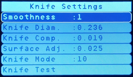
54 54 Vision 16 and 25 Series Router User Manual The parameters that need to be set are located in the Knife Settings portion of the Menu. Use the Y Up of Down keys on the Pendant and highlight Knife Settings, then press the Enter key on the Pendant. Setting Details: Smoothness adjusts the amount any curves drawn in the job are smoothed out. Common settings are either 1 or 2. A setting or 0 will replicate the graphic most accurately, but may cause excessive stopping and starting when cutting. Settings of 3 or more "can" be used, but the amount of smoothing applied at these higher numbers provides little benefit. Knife Diam. is the diameter of the knife being used. All knives sold by Vision are 0.236" diameter. There is no need to adjust this unless the user has purchased special knives. Knife Comp. is a setting used to compensate for the width of the knife being used and for the thickness of the material being cut. This setting MUST be adjusted to properly cut materials. Use the table below to enter the Knife Compensation for the material thicknesses listed. Surface Adj. is the amount of "over cut" desired to completely cut through a material. This setting will depend on the material as well as whether the material is placed on top of the Cutting Pad or Multimat materials. Experimentation is necessary in order to provide a balance of complete cut through and to minimize damage to the Cutting Pad or Multimat. HINT: Common settings will range from 0.005" to 0.030". Do not exceed 0.035". Knife Mode is always set to 10. Do not change this setting. Knife Test allows the user to rotate the knife using the Z Up or Down keys on the Pendant. This is only used for diagnostic purposes.
55 Oscillating Knife 55
56 56 Vision 16 and 25 Series Router User Manual Knife Compensation Table Measure the thickness of the material to be cut and enter the corresponding Knife Compensation in the Knife Comp field of the machine's Pendant. Use the numeric keys to enter numbers. Press the Enter key on the Pendant to save the number entered. If the thickness of the material lies between the thicknesses shown here, enter the average compensation settings. Example: The material measures 0.112" thick, for the E12 knife, use a Knife Compensation of
. Below is the procedure to set the surface.")
57 Oscillating Knife 57 Setting Surface When running jobs with the Oscillating Knife, the surface must be set on the machine to the top of either the Cutting Pad (for machines with the Vacuum Table), or the MultiMat material (for machines with TSlot Tables). Below is the procedure to set the surface. Turn on the machine's controller, home the machine and move the spindle over to a location near the middle of the table. If using the Cutting Pad, TURN ON THE VACUUM PUMP. The vacuum pump must be running to pull the Cutting Pad and MDF Board down against the vacuum table, otherwise the surface set in this procedure will not be accurate and incomplete cutting will result. Plug the Surface Block Connector into the Port on the back of the Carriage and place the Surface Block on the Cutting Pad under the Knife Blade as shown.

58 58 Vision 16 and 25 Series Router User Manual Lower the spindle using the Z Down Key on the Pendant until the tip of the knife is approximately 1 inch above the Surface Block.
59 Oscillating Knife 59 WARNING: ONCE THE SET SURFACE KEY ON THE PENDANT IS PRESSED IN THE NEXT STEP, THE KNIFE WILL BEGIN OSCILLATING. KEEP HANDS AND CLOTHING AWAY FROM THE KNIFE OR SEVERE INJURY MAY RESULT. Press the Set Surface Key on the Pendant. The knife will begin moving up and down (oscillating). Hold the Surface Block down FIRMLY, then press and HOLD the Set Surface Key down. The spindle will slowly start to move down toward the Surface Block. When the tip of the knife touches the Surface Block, the spindle will move back up and the knife will stop oscillating. Release the Set Surface Key at this time. The surface of the Cutting Pad (or MultiMat) is then stored in the machine's controller and the Set Surface procedure is complete. Press Go To Home on the Pendant and unplug the Set Surface Block Connector from the Carriage.

60 60 Vision 16 and 25 Series Router User Manual Setting Up Cut Files Open the Vision Software. The first step in creating cut files is to understand that the Oscillating Knife ONLY recognizes objects drawn in PEN 31. To create a custom pen using pen 31 in any color desired, double click on any of the color swatches at the bottom of the Vision software screen. In this example, the Red color swatch was chosen. The Edit Color window will appear. Change the Pen to 31. Click on Add once these changes have been made.
 S4 for all 16 and 25 Series machines.")
61 Oscillating Knife 61 A new color swatch will be added to the swatch bar. Select this color swatch by clicking once on it. All graphics drawn will use this color. After creating the cut file, select the Engrave icon from the left toolbar. Then set the Device as the Oscillating Knife (small router) S4 for all 16 and 25 Series machines. If this Device is not listed, install this Device by closing the Cut Toolbox and selecting File > Install > Cutting Devices, then selecting this Device from the list under options for your Vision Routers S4 (2'x4' and smaller). Select the Tool Setup icon (to the right of the Tool field on the top toolbar. The Tool Setup window for the Oscillating Knife will appear. Choose either the Default setting, the Cardboard setting, or modify the settings for Oscillation RPM and/or Cutting rate to optimize cutting the substrate being used. Select OK when finished, then send the job to the machine by clicking on the engrave icon in the Cut Toolbox. The usable range of RPM is between 3,500 and 7,000 RPM. Cutting Rate settings are typically from 0.5 to 2.0 IPS. The user is advised to run test cuts in their materials and save the desired settings by using the Add Material icon. Since there are many combinations of knife, material and desired cut quality/speed, the user should become familiar with running test files to determine what settings work "best" for their applications.

62 62 Vision 16 and 25 Series Router User Manual For further instructions on using the Oscillating Knife, please contact Vision technical support

63 Oscillating Knife 14 The DACS Camera System 14.1 DACS Test File 63 The below image is of a file included with your software installation. The file is named DACS Test.cdl, which can be used to perform and verify the set up procedure detailed in the following sections. The test file is installed on your computer with the Vision software and located in C:\Vision Express 9\Vision jobs. (or C:\Vision Expert 9\Vision jobs, or C:\Vision Pro 9\Vision jobs, depending on your version of the Vision software). Please open the DACS Test.cdl file in your Vision software and print it at 100% scale. The file is designed to be printed on a standard letter (8.5" x 11") sized paper. The printed image can then be adhered to a solid piece of material, such as acrylic, in order to perform the set up procedure.
 to install Vision Machine Tools. You may also download the newest version of Machine Tools from www.visionengravers.")
64 Vision 16 and 25 Series Router User Manual Setting Up the DACS Camera System Machine Tools Installation Install Vision Machine Tools - The VISION USB drive (or orange dongle used with the Vision software) contains a folder named Vision Machine Tools v4. Open Windows Explorer and open this folder and double click on Setup (or Setup.exe) to install Vision Machine Tools. You may also download the newest version of Machine Tools from in the Support, Download Software, Drivers and Utilities page. Once Machine Tools is installed, go to the folder named Dongle74 on your computer. It is located in C:\Program Files (x86)\vision Machine Tools 4\Dongle74. Double click to run the file named Dongle74 (or Dongle74.exe) inside this folder. This file was installed with the Vision Machine Tools software in the previous step. NOTE - The location of this file may be different on your computer depending on which version of Windows you are using. You can run a search for "Dongle74.exe" on your computer to find the file.
. Open the folder named Camera, then open the folder named Sentech Ethernet camera.")
65 The DACS Camera System Ethernet Camera Driver Installation Install the DACS Camera dongle into an available USB port on your computer. Open Windows Explorer and open the VISION USB drive (this is the drive for your orange Vision dongle). Open the folder named Camera, then open the folder named Sentech Ethernet camera. Double click on either the file named StGigE-Package_x86.exe for 32 bit operating systems, or StGigEPackage_x64.exe for 64 bit operating systems. If your computer asks if you want to run this file, click on Yes or Run. This file will install the driver needed to run the Ethernet DACS Camera. Go through and complete the installation for the Sentech Standard GigE Vision Camera. When finished, you will need to reboot your computer for the changes to take effect. Once your computer has rebooted, add a shortcut for the VisionTool4 (or VisionTool4.exe) program to your desktop. Open the folder C:\Program Files (x86)\vision Machine Tools 4. Right click on VisionTool4, select Send to, then click on Desktop (create shortcut). The shortcut created will look like this.

66 66 Vision 16 and 25 Series Router User Manual Right click on this shortcut and click on Rename, then rename it to DACS.

67 The DACS Camera System Ethernet Camera Software Setup IMPORTANT NOTE: The Ethernet DACS camera requires the Vision Controller to be connected to your computer or network via a STATIC IP Address. Please refer to the sections of your Series 4 Controller Manual regarding connecting your Controller using a Static IP Address, or call Vision technical support To begin setting up the Ethernet Camera, first, turn the power on to your machine's Controller and wait until it has initialized. Press Go to Limits on the Pendant. Connect an Ethernet cable from the supplied network hub to the Ethernet plug on the side of your Vision 16 Series or 25 Series Router with the supplied 15' Ethernet cable. Make sure the 3' Ethernet cable and camera power cable (also supplied) are both connected from the rear of the router's carriage to the top of the DACS camera. NOTE - Refer to the Using a Network Hub section of your Series 4 Controller Manual in order to properly set up the connection between your computer and the router, using a network hub. Refer to the below diagram for proper cable connections. Open the DACS (VisionTool4) software using the newly created shortcut, then select your machine in the Select Connection window and click on OK. If there is only one machine connected to your computer, this list will not appear.

68 68 Vision 16 and 25 Series Router User Manual Select File from the top menu bar and click on XMI Settings. Select GigE_ST under Camera Settings as the Type. After selecting the camera, the following screen may appear. If so, select OK and then OK to close the XMI Settings window, then close and reopen the DACS software. Go back to File > XMI Settings to proceed.

69 The DACS Camera System 69 The following settings will need to be changed depending on which engraver or router is being used. For 16 Series, 24 Series and 25 Series machines: Flip Image - Horizontal, Rotate Image The camera IP address must be set. Select the Configure icon next to the Camera Type. The following window will appear. Note - if the camera is not listed in the available device list, place a check mark in the box in the lower left corner of this window - Show unreachable GigE Vision Devices.

70 70 Vision 16 and 25 Series Router User Manual Highlight the STC camera by clicking on the icon under the Available GigE Vision Devices list. If selected, it will highlight in blue as shown. Then, select Set IP Address... at the bottom of this screen. Type in the IP address as shown below and select OK. (Make sure you are using a STATIC IP Address and the recommended IP Address settings for your computer and the machine's controller). Select OK when finished with this window, the Device window and the XMI Setting window. You may be prompted to restart the DACS (VisionTool4) software. Click on OK and close/re-open the DACS software.

71 The DACS Camera System Camera Adjustments Place a graphic containing 0.25 inch diameter fiducial markers on the machine's table, then roughly center the camera over one of the fiducial markers using the X and Y move buttons on the Pendant. It is best to use a graphic that contains both 0.25 inch diameter fiducial markers as well as detailed images, such as small text, in order to properly adjust the camera. Remove the camera's lens cover, then click on the Live Camera Feed icon on the top toolbar of the DACS software.

72 72 Vision 16 and 25 Series Router User Manual An image may or may not appear on screen at this time. Select File from the top menu bar and click on Exposure Control. Adjust the Exposure near the middle of its adjustment, then click on OK. Again, an image may still not appear. It is possible that the camera's aperture is adjusted to over or under-expose the image. To adjust the aperture and change the amount of light entering the camera, loosen the bottom thumbscrew on the camera and turn the aperture adjustment ring below it to the left or right. Watch the image on the DACS software screen. As the aperture is adjusted, the screen image will become lighter or darker. The camera focus may also need to be adjusted. This is best performed after the aperture is adjusted.

73 The DACS Camera System 73 Below are 4 images depicting under-exposed, over-exposed and properly exposed/focused images. Adjust the aperture to provide enough contrast to view all image details, then adjust the camera focus to show the image as clearly as possible. To adjust focus, first make sure the thumbscrew for the aperture adjustment has been tightened (this may adjust exposure slightly), then loosen the top thumbscrew on the camera and turn the focus adjustment until the image shown on screen is crisp. Tighten the top thumbscrew once the focus has been adjusted.

74 74 Vision 16 and 25 Series Router User Manual Vision Series 4 Controller Configuration The Vision Series 4 Controller must be configured for the DACS Camera. Open the menu by pressing the Menu button on the Pendant. Scroll down to highlight DACS and press the Enter button on the Pendant. To adjust or set any of the parameters, scroll down and highlight the setting and press the Enter button on the Pendant. There are two menu screens as shown below. The Fiducial Diameter should be set to To set this value, highlight Fiducial Diameter and press the Enter button on the Pendant, enter 0.25 using the Pendant's numeric keypad, then press Enter on the keypad. The Correlation should be set to To set this value, highlight Correlation, press Enter, enter and press Enter to set this value.

75 The DACS Camera System The Retake Distance default value is , and should not need to be changed. The Settling Time default value is 200 and should not need to be changed. Flip to Cut should be set to "No". Auto Focus should be set to "No". 75

76 76 Vision 16 and 25 Series Router User Manual To set the Auto Find setting, highlight it in the menu, press the Enter button, then enter the value 0.2 using the Pendant's numeric keypad. Press Enter to save this setting. Highlight Manual Find Setting and press Enter on the Pendant. Use the up or down Y arrow buttons on the Pendant to select >> Jog Camera to Fid, then press Enter to save this setting. To set the Camera Scale, first exit the Pendant's menu, then press the Go to Limits button on the Pendant, then press Set Home and then Enter. Press the Menu button, highlight DACS and press Enter, highlight Set Camera Scale and press the Enter button 2 times. The below screen should be seen at this point. Press Enter one more time. Using the X and Y Arrow buttons on the Pendant, jog the camera so that a fiducial marker can be seen in the center of the DACS software screen, then press Enter on the Pendant.

77 The DACS Camera System 77 The Controller will calculate the camera scale and set it automatically. Press Enter on the Pendant to exit this screen. In order to set the Camera Offset, first install a cutter UPSIDE DOWN in the spindle so that the flat end of the cutter extends below the nose cone. Jog the motion system over the top of a fiducial marker, lower the spindle until the cutter almost touches the material, then use the X and Y Arrow buttons to center the cutter over the fiducial marker as shown. Press Set Home, then Enter on the Pendant. Press Go to Home, then press Set Surface and then press Enter. Press the Prox On/Off button and set the Prox to OFF. Press the Spindle On/Off button and set the spindle to OFF. Go to the Menu on the Pendant, select DACS, then Set Camera Offset. The screen should appear as below. Press Enter to mark the current Home Position as where the fiducial marker is located (this is why the Home was set over the fiducial marker in the prior step). Press the Go to Home button and remove the cutter.

78 78 Vision 16 and 25 Series Router User Manual CAUTION - the spindle and motion system will run a short file after the Start button is pressed in the next step. Keep hands or other items away from the machine! Press the Start button on the Pendant. CAUTION - The spindle should not turn on and it should not move down toward the material surface. If this happens, press Pause and Cancel. Check to make sure the Spindle and Prox are turned off and restart this procedure beginning with setting the camera scale. After the file has run, use the X and Y Arrow buttons to jog the motion system so that the SAME fiducial marker used can be seen in the center of the DACS software window. Try to get the marker as close to the center of the window as possible.

79 The DACS Camera System 79 Press Enter on the Pendant. The Camera System will locate the fiducial marker. When the fiducial marker has been found, a blue box and cross-hair will be displayed in the DACS software over the marker and the offset will be saved. Press the Enter button on the Pendant to complete the set up.

80 80 Vision 16 and 25 Series Router User Manual Vision Software Setup A special DACS device driver will need to be installed in the Vision software. Open the Vision software and select File from the top menu bar, then select Install and click on Cutting Devices. For Vision Engravers, click on Vision Engravers S4 in the Manufacturer column. For Vision Routers, click on either Vision Routers S4 (2'x4' and smalle, or Vision Routers S4 (4'x8' and larger) in the Manufacturer column. Place a check mark in the box next to Vision DACS S4, or Vision Router DACS S4 in the Output Device column. Keep any other Output Devices previously selected (do not uncheck any output devices, unless you want to delete them). Then click on Next. Since Vision Machine Tools will now be controlling how files are sent to the engraver or router, any previously installed device drivers will need to be set up to properly send jobs from the Vision software to the machine.

81 The DACS Camera System 81 In the Vision software, select Engrave from the top menu bar, then click on Engraving Defaults. Plot window will now be shown. Select the previously installed device in the Selected Device field, then click on Setup. Note - if you have several machines, please contact Vision Technical Support to set up individual folders for each device. Select the Port tab, then select Direct to Port in the Method area - the Path shown should be c:\vision Machine Tools\Inbox. If this not the case, select Set Path and correct it. Set Port Location to File, then click on Apply, then OK. Click on Apply, then Close in the Plot window. Set up is now complete.

82 Vision 16 and 25 Series Router User Manual Using the DACS Camera System This section covers how to use a DACS Camera System that has been properly installed and set up. For instructions on how to set up the software and adjust the camera's parameters, skip to the following section. In order to use the DACS Camera System, files need to be set up in the Vision 9 software with a minimum of 3 Fiducial Markers located within the plate area and surrounding the graphics to be cut out with the router or engraver. The printed diameter of these Fiducials should be 0.25 inches. The Fiducials should be printed in black. An example of a file that has been set up is shown below. Note that the Fiducials are not randomly placed within the plate, rather, they are placed along a common X or Y axis and at right angles to each other. Note: If the material is to be located on the table with the upper left corner of the material in the upper left corner of the table (home position), Fiducials must be placed far enough from the edge of the material so that the DACS Camera can find them. As a general rule for all engravers and routers, locate the Fiducials at least 3 inches from the top and 3 inches from the left of the machine's home position (the top left corner of the machine). Also, try to keep Fiducials spaced at least 3 inches from each other so the Camera System does not select the wrong Fiducial before running the file. It is also good practice to locate Fiducials away from circular graphics, such as the letter O, or other round graphics. Doing so may cause the Camera System to mistake a portion of the graphics as a Fiducial and improperly position the cut tool path. Fiducials should not be randomly placed within the plate.

83 The DACS Camera System 83 Once the design has been finished, the Fiducials need to be changed to Pen 99 in the Vision software. This is mandatory, as the DACS software looks for objects drawn in Pen 99 and identifies those objects as Fiducials. If you have drawn the Fiducials in the Vision software (as 0.25 inch diameter circles), follow the steps below to change the color/pen of the Fiducials to Pen 99. Step1 -. Select View from the top menu bar, and make sure Show Fill is not checked. Step 2 - Select all Fiducials and move the mouse pointer over a color swatch on the bottom color swatch list to a color that you do not normally use, such as Orange (shown below).

84 84 Vision 16 and 25 Series Router User Manual Double-click on the color swatch and click on the General tab at the top of the screen. In the Color name entry field, type in Fiducial, then change the Pen to 99. Select Add to save this color swatch and exit the Edit Color window. Now, right-click, then left-click on the new color swatch you've just created to change both the outline and fill color to this new color named "Fiducial". Note that the number shown on the color swatch is NOT the pen number, but the position number of the color swatch on the color swatch bar. If you need to check the pen number, simply double-click on the color swatch to see the pen number assigned.

85 The DACS Camera System 85 Now that the Fiducials have been set to Pen 99, select only 3 of the Fiducials that you want to have the Camera System use for positioning. It is good practice to look at the Fiducials that are printed on your material and choose 3 of them that have been printed clearly and form a right angle. In the below picture, the top right Fiducial was deleted from the drawing and the remaining 3 Fiducials remained for the DACS software to use. Create a tool path for the items you want to cut. In this example, a male tool path was created around the Vision logo. Note that in areas where there are internal corners, the tool path may allow for white areas to be exposed after cutting. In order to correct this problem, either the print bleed needs to be increased, the graphics need to be modified to widen the angle of these interior corners, the tool path needs to be adjusted to have a negative Gap (which will cut into the graphics in all areas by the amount of negative Gap), or a smaller diameter tool will need to be used.
, or after clicking on the Engrave icon on the left toolbar.")
86 86 Vision 16 and 25 Series Router User Manual Before sending the file to the machine, make sure you have selected the DACS driver for your machine. This can be done by selecting the Plate Size icon on the top toolbar (as shown), or after clicking on the Engrave icon on the left toolbar. Click on the Machine Tools icon located on the bottom right corner of the Windows Taskbar.

87 The DACS Camera System 87 Make sure that Job Name Server is checked for your machine. This is necessary so that the Machine Tools software sends the file to the correct machine. Open the DACS software. The DACS software icon should be on your computer's desktop. When opening the DACS software, you will be prompted to select the machine to which you are connected. Choose your machine and click on OK. If you only have one machine, this window will not appear.

88 88 Vision 16 and 25 Series Router User Manual Once the DACS software has opened, click on the Live Camera Feed icon. You may wish to jog the motion system over one of the Fiducial Markers to make sure it shows up correctly as shown below. Before sending the job to the machine, a good practice is to check that 4 procedures have been performed. 1. Material Set. The material is positioned at the top left corner of the table. 2. Tool Set. The proper cutting tool has been installed. 3. Surface Set. The Set Surface procedure has been performed (if the Proximity Sensor is not being used). 4. Home Set. The machine's home has been set to the material's upper left corner (the machine's home position, if the material is positioned as suggested here).

89 The DACS Camera System 89 After clicking on the Engrave icon on the left toolbar, make sure the DACS driver is selected as your device. (DACS driver for small routers is shown in the below picture). Send the job to the machine. When running Machine Tools, which is necessary when using the DACS Camera System, the Pendant will show a preview of the job you have sent to the machine. Press Start on the Pendant. The job will be recognized as using the DACS Camera and you will be prompted to press Start to have the machine find the Fiducial Markers. Once the Fiducial Markers have been located by the DACS software, the machine will pause and any adjustments needed to properly position the tool path will be made automatically. You will be promoted to press Start to begin running the job at this time. If the Fiducials are not found when running the job, you will be prompted to jog the motion system to the first Fiducial Marker. Jog the motion system so that the top left Fiducial is displayed on the DACS software screen. Follow the Pendant's on screen commands to have the camera system find the Fiducial Markers and properly locate the cut tool path. Then, run the job. If you have any issues when running the DACS Camera System, please contact Vision Technical Support
90 90 15 Vision 16 and 25 Series Router User Manual UNIST Misting System The optional UNIST Misting System is designed to provide lubrication to the cutting tool and material when processing metals. The diagram shown below lists the main components and connections. This system requires a compressed air supply (60 PSI Max) to be connected to the inlet air line. Documentation for usage of the UNIST Misting System is included with the system. Please refer to this documentation for operation details.
91 UNIST Misting System 91 Additionally, the Misting System Power Plug on the router connects to the controller's Pump/Mist port with the supplied cable.
92 92 16 Vision 16 and 25 Series Router User Manual Maintenance Vision strives for the highest quality in their manufacturing process to provide you with the most cost effective, reliable engraving machine in use today. Please remember that proper maintenance and care is necessary to achieve maximum product life expectancy. The engraving environment generates small plastic and metal chips as well as other particles during operation. As with any machinery, your engraving system should be kept as clean as possible to minimize wear and tear and to improve final quality of the engraved product. Removing Chips A portable vacuum is suggested for chip removal, but applying direct suction to the spindle area is not recommended. Note that this cleaning can be minimized and greatly simplified through the use of the optional vacuum chip removal system. The vacuum chip removal system removes chips and dust created by engraving. This system can also extend the life of other components in the system, as prompt removal of chips reduces contamination and overheating in the spindle area. The vacuum chip removal system also keeps the nose cone from skipping over letters due to chips that would otherwise remain on the engraving surface. The Vacuum Chip Removal System The optional vacuum chip removal system is designed to simplify the engraving process and minimize wear and tear on the engraver. The vacuum chip removal system uses a vacuum nose cone to remove chips created during the engraving process before they have the chance to create problems. The quiet pump, coupled with the micro-fine layered filters, assures that your unwanted chips are whisked away effortlessly. The vacuum pump canister uses reusable filters to assure maximum efficiency and costeffectiveness. Engraving Head and High Speed Spindle Drive Belt Replacement A belt is used to drive the engraver's spindle. It runs between the motor pulley and the spindle pulley. If it needs replacement, remove the old belt by rolling it to the top of the spindle pulley, then slightly stretching the belt to snap it over the top of the spindle pulley. Once loose, it can easily be removed. To install the new belt, position the new belt around the drive pulley, then lightly stretch it to snap over the top of the spindle pulley. NOTE: Be sure to purchase the specified replacement belt from Vision Engraving Systems. Having the correct belt size is extremely important to the functionality of the motor. NEVER EXCESSIVELY STRETCH THE BELT!
93 Maintenance Engraving Head High Speed Engraving Spindle 93

94 94 Vision 16 and 25 Series Router User Manual Lubricating the X-Axis, Y-Axis and Z-Axis Leadscrews (ALL MODELS) A light lubrication of the X, Y and Z-Axis leadscrews should be performed after every month of usage. Use Teflon-Free Silicone lubricant spray only. Spray a light coating along the entire leadscrew. Note: A nozzle extender attached to the aerosol spray can help facilitate this procedure. DO NOT use any lubricant other than Teflon-Free Silicone, as it may become sticky and cause a buildup that will cause mechanical failure. The X, Y and Z-Axis linear rails should be wiped down with a clean, dry cloth each week, or when debris has built up on the rails. The Z-Axis linear rails are underneath a cover mounted to the rail plate. In order to access the Z-Axis rails, the Z-Axis must be lowered. The X and Y-Axis linear rails have grease fittings (shown below). Greasing of these fittings should only be performed every 6 months or so. Only 1/2-1 pump of grease is required. DO NOT apply grease until grease comes out of the bearing seals. This will deform the seals and allow debris into the bearings. Although there are grease fitting on the Z-Axis linear rails, the cover protects the rails and lubrication is not required.

95 Maintenance 95
Vision Engravers and Routers PRE-Installation Guide. 2015 Vision Engraving & Routing Systems
 Vision Engravers and Routers PRE-Installation Guide Revised: 8/19/2015 Vision Engravers and Routers PRE-Installation Guide All rights reserved. No parts of this work may be reproduced in any form or by
Multi Axis Engraver. Operations Manual. Vision Engraving & Routing Systems 17621 N. Black Canyon Hwy. Phoenix, AZ 85023 www.visionengravers.
 Multi Axis Engraver Operations Manual Vision Engraving & Routing Systems 17621 N. Black Canyon Hwy. Phoenix, AZ 85023 www.visionengravers.com Copyright 2005 Vision Computerized Engraving & Routing Systems
Vision Express User Manual. 2015 Vision Engraving & Routing Systems
 Vision Express User Manual Revised: 8/19/2015 Vision Express User Manual All rights reserved. No parts of this work may be reproduced in any form or by any means - graphic, electronic, or mechanical, including
Control Box Wiring For PRSstandard Tool
 888-680-4466 ShopBotTools.com Control Box Wiring For PRSstandard Tool Copyright 2016 ShopBot Tools, Inc. page 1 Copyright 2016 ShopBot Tools, Inc. page 2 Table of Contents Introduction:...5 Installation:...5
Mini-led spotlight with magnetic base
 Mini-led spotlight with magnetic base Model 95799 Assembly And Operation Instructions Due to continuing improvements, actual product may differ slightly from the product described herein. 3491 Mission
tire inflator with pressure gauge
 tire inflator with pressure gauge Model 95583 Assembly And Operation Instructions Due to continuing improvements, actual product may differ slightly from the product described herein. 3491 Mission Oaks
Instructions and precautions. Fork Height. Visit our website at: http://www.harborfreight.com
 Pallet Jack Item 68760 / 68761 Instructions and precautions Specifications Capacity Control Lever Fork Height Fork Length Fork Width Maximum Minimum Width over Forks Steering Wheel Dia. 2-1/2 Ton (5,000
15GAL STEEL OIL DRAIN WITH 110V PUMP
 15GAL STEEL OIL DRAIN WITH 110V PUMP OWNER S MANUAL WARNING: Read carefully and understand all ASSEMBLY AND OPERATION INSTRUCTIONS before operating. Failure to follow the safety rules and other basic safety
ROUTER TABLE INSERT ASSEMBLY AND OPERATING INSTRUCTIONS
 ROUTER TABLE INSERT 94331 ASSEMBLY AND OPERATING INSTRUCTIONS 3491 Mission Oaks Blvd., Camarillo, CA 93011 Visit our Web site at http://www.harborfreight.com Copyright 2006 by Harbor Freight Tools. All
USE &CARE GUIDE. Remote Faucet Pump System. See Important Safeguards on page 2
 Remote Faucet Pump System USE &CARE GUIDE See Important Safeguards on page 2 An exclamation point within an equilateral triangle is intended to alert user to the presence of important operating and maintenance
MBSAW. Meat Cutting Band Saw With Meat Grinder Assembly & Operating Instructions
 06/2011 MBSAW Meat Cutting Band Saw With Meat Grinder Assembly & Operating Instructions READ ALL INSTRUCTIONS AND WARNINGS BEFORE USING THIS PRODUCT. This manual provides important information on proper
PNEUMATIC PLANISHING HAMMER
 PNEUMATIC PLANISHING HAMMER 94847 ASSEMBLY AND OPERATING INSTRUCTIONS Due to continuing improvements, actual product may differ slightly from the product described herein. Distributed Exclusively by Harbor
Hydraulic Punch Driver Kit
 Hydraulic Punch Driver Kit Item 96718 Instructions and precautions Visit our website at: http://www.harborfreight.com Read this material before using this product. Failure to do so can result in serious
Table of Contents WARNING SYMBOLS AND DEFINITIONS
 Table of Contents SAFETY INSTALLATION OPERATION MAINTENANCE Safety... 2 Specifications... 4 Installation... 5 Operation... 8 WARNING SYMBOLS AND DEFINITIONS Maintenance... 9 Parts List and Assembly Diagram...
PALLET JACK - 2.5 TON
 PALLET JACK - 2.5 TON 39939 SET UP AND OPERATING INSTRUCTIONS Visit our website at: http://www.harborfreight.com Read this material before using this product. Failure to do so can result in serious injury.
Table of Contents. www.hunterfan.com. What to Expect with. Preparation. Tools Needed. Wiring. Hanging the Fan. Blades. Motor Housing.
 www.hunterfan.com Table of Contents What to Expect with Your Installation 30 inches Hanging the Fan Wiring 8 Maintenance, Operation & Cleaning Light Kit 13??? 14 1 9 Troubleshooting 11 5 Blades Motor Housing
Triple Threat 3-in-1 Game Table 3 IN 1 GAME TABLE
 NG0M Triple Threat 3-in- Game Table 3 IN GAME TABLE Thank 3 in Y Game Table Thank you for your purchase of our product. We work around the clock and around the globe to ensure that our products maintain
COMPACT ELITE MAT CUTTER
 INSTRUCTION MANUAL MODEL 350-1 COMPACT ELITE MAT CUTTER INSTRUCTIONS AND OPERATION MANUAL 32in (81cm) mat cutting system with bevel & straight cutters, production stops and 20 in (51 cm) squaring bar.
WARNING CANADIAN D.O.C. WARNING
 Each product and program carries a respective written warranty, the only warranty on which the customer can rely. Avery Dennison Corp. reserves the right to make changes in the product, the programs, and
TITAN 13 x 2 ½ BRAKES
 INSTALLATION INSTRUCTION AND SERVICE MANUAL Actuator/Trailer Dealer - Please provide these instructions to the consumer. Consumer - Read and follow these instructions. Keep them with the trailer for future
Speed-Mat Rectangle Cutter
 Speed-Mat Rectangle Cutter 1 Honeycomb baseboard. 2 Left hold down. 14 3 Bottom hold down. 4 4 Left / right rule. 8 5 8 5 Left / right rule pointer. 1 6 Top / bottom rule. 7 Top / bottom rule pointer.
BUILT-IN DISHWASHER INSTALLATION INSTRUCTIONS
 BUILT-IN DISHWASHER INSTALLATION INSTRUCTIONS PLEASE READ COMPLETE INSTRUCTIONS BEFORE YOU BEGIN LEAVE INSTALLATION INSTRUCTIONS AND USER'S GUIDE WITH OWNER ALL ELECTRIC WIRING AND PLUMBING MUST BE DONE
Operating Manual Please Read Before Operating Unit
 Operating Manual Please Read Before Operating Unit Model RT2S Wire Stripper & Component Lead Cleaner Service and All Spare Parts Available The Eraser Company, Inc. PO Box 4961/ Oliva Drive Syracuse, NY
OWNER S MANUAL DRAINVAC ATOMIK PRINTED APRIL 4-2011
 OWNER S MANUAL th DRAINVAC ATOMIK PRINTED APRIL 4-2011 INTRODUCTION We take this opportunity to express our gratitude and extend our congratulations for your decision to purchase a Drainvac product. A
758 Heavy-duty Ratchet Guy Wire Cutter
 INSTRUCTION MANUAL 758 Heavy-duty Ratchet Guy Wire Cutter Read and understand all of the instructions and safety information in this manual before operating or servicing this tool. Register this product
1000-LB. TRAILER JACK OWNER S MANUAL
 1000-LB. TRAILER JACK OWNER S MANUAL WARNING: Read carefully and understand all INSTRUCTIONS before operating. Failure to follow the safety rules and other basic safety precautions may result in serious
Cable Drum Machine. Operation Manual BC260 SERIES. Cleans 1 1/4" to 3" lines up to 50'
 Cable Drum Machine Operation Manual BC260 SERIES Cleans 1 1/4" to 3" lines up to 50' Used For: Sink, Shower & Floor Drains 42FM " WARNING - Read All Instructions, When Using Electric Tools, Basic Safety
FASCINATION 700 HVLP TANNING PRO SYSTEM USER MANUAL
 FASCINATION 700 HVLP TANNING PRO SYSTEM USER MANUAL Congratulations on choosing the Fascination 700 HVLP Tanning Pro System! Your system includes the following items: 1 Fascination 700 HVLP Tanning Pro
ATS Overhead Table Shelf System INSTRUCTION MANUAL
 ATS Overhead Table Shelf System INSTRUCTION MANUAL ATS Overhead Table Shelf System Instruction Manual Warranty Newport Corporation warrants this product to be free of defects in material and workmanship
1 HP MINI DUST COLLECTOR
 1 HP MINI DUST COLLECTOR 31810 Set up and Operating Instructions Visit our website at: http://www.harborfreight.com Read this material before using this product. Failure to do so can result in serious
staple gun with 5/16 Long staples
 staple gun with 5/16 Long staples Model 95718 Assembly And Operation Instructions Due to continuing improvements, actual product may differ slightly from the product described herein. 3491 Mission Oaks
Operating Instructions Drill rig DRU160
 Operating Instructions Drill rig DRU160 Index 000 / 001 Original operating instructions 10988825 en / 20.10.2009 Congratulations! With a Hydrostress unit from TYROLIT you have chosen a tried and tested
PEDAL CAR - GO CART ASSEMBLY & OPERATING INSTRUCTIONS
 PEDAL CAR - GO CART 42822 ASSEMBLY & OPERATING INSTRUCTIONS 3491 Mission Oaks Blvd., Camarillo, CA 93011 Visit our Web site at: http://www.harborfreight.com Copyright 2000 by Harbor Freight Tools. All
Ultraviolet Germicidal Lamps Owner s Manual MODELS 1910 & 1930
 Ultraviolet Germicidal Lamps Owner s Manual MODELS 1910 & 1930 WARNING Ultraviolet light is harmful to eyes and skin. Never look at light produced by this lamp. Unplug lamp before servicing. Electrical
National- Spencer Inc.
 9-27-2010 National- Spencer Inc. 19.2V HEAVY DUTY GREASE GUN PRODUCT SPECIFICATION Charger Input Power 110 VAC Battery Output Power 19.2V Battery Capacity 1500 MAH Battery Pack Charge Time 1 Hour Maximum
Pet hair clipper. Model 96822. Diagrams within this manual may not be drawn proportionally.
 Pet hair clipper Model 96822 Cleaning And Operation Instructions Diagrams within this manual may not be drawn proportionally. Due to continuing improvements, actual product may differ slightly from the
Digital Fingerprint safe
 Digital Fingerprint safe Model 96846 Operation Instructions Diagrams within this manual may not be drawn proportionally. Due to continuing improvements, actual product may differ slightly from the product
Flat Bottom Long Ram Hydraulic Jack
 Flat Bottom Long Ram Hydraulic Jack 3 Ton 8 Ton 36468 36469 ASSEMBLY & OPERATING INSTRUCTIONS 349 Mission Oaks Blvd., Camarillo, CA 930 Visit our Web site at http://www.harborfreight.com TO PREVENT SERIOUS
Andersen Electric Window Opener for Andersen Awning and Roof Windows
 W A Electric Window Opener Electric Window Opener for Awning and Roof Windows Congratulations! You have just purchased one of the many fine products. For ease of installation and continued enjoyment of
SAFETY & OPERATING INSTRUCTIONS
 SAFETY & OPERATING INSTRUCTIONS EDLUND TOMATO LASER, Models ETL -316, -140 & -380 READ AND UNDERSTAND THIS MANUAL AND ALL INSTRUCTIONS BEFORE OPERATING THIS SLICER. 159 Industrial Parkway, Burlington,
Installation Instructions 4508 4508S
 SYMPHONY Spread Lavatory Faucet with Speed Connect Drain Congratulations on purchasing your American Standard faucet with Speed Connect drain, a feature found only on American Standard faucets. Speed Connect
3/4 PIPE CLAMP WITH STAND
 3/4 PIPE CLAMP WITH STAND Model 94053 ASSEMBLY AND OPERATING INSTRUCTIONS (3/4 DIAMETER PIPE NOT INCLUDED.) 3491 Mission Oaks Blvd., Camarillo, CA 93011 Visit our Web site at: http://www.harborfreight.com
16/32 Channel 1U Rack Mount CCTV Power Supply
 16/32 Channel 1U Rack Mount CCTV Power Supply Manual PH-A3224-GUQ Shown 16-Channel 32-Channel PTC PH-A1612-PUQ PH-A3224-PUQ Glass Fuse PH-A1612-GUQ PH-A3224-GUQ Industrial design 12 Amp 3 Amps per channel
SBC90. Abrasive Blast Cabinet Assembly & Operating Instructions
 SBC90 Abrasive Blast Cabinet Assembly & Operating Instructions READ ALL INSTRUCTIONS AND WARNINGS BEFORE USING THIS PRODUCT. SAVE THESE INSTRUCTIONS FOR FUTURE REFERENCE. This manual provides important
FJ2. 2 Ton Trolley Floor Jack Assembly & Operating Instructions
 FJ2 2 Ton Trolley Floor Jack Assembly & Operating Instructions READ ALL INSTRUCTIONS AND WARNINGS BEFORE USING THIS PRODUCT. This manual provides important information on proper operation & maintenance.
LU6X-130 Instructions and Parts List (including LU6X Basic) Operating Instructions
 Operating Instructions") LORTONE LU6X-130 Item # 061-092 LU6X Basic Item # 061-090 LU6X-130 Instructions and Parts List (including LU6X Basic) Operating Instructions Introduction The LU6X is one the most versatile pieces of equipment
LORTONE LU6X-130 Item # 061-092 LU6X Basic Item # 061-090 LU6X-130 Instructions and Parts List (including LU6X Basic) Operating Instructions Introduction The LU6X is one the most versatile pieces of equipment
DTM04 TANK MONITOR DTM08 TANK MONITOR Dtm12 TANK MONITOR. Installation and Operation Manual
 DTM04 TANK MONITOR DTM08 TANK MONITOR Dtm12 TANK MONITOR Installation and Operation Manual 1 ENGLISH Safety Instructions 2 Features 2-3 Specifications 3 Installation 4-5 Wiring Diagrams 6-7 Warranty 8
OAK WORKBENCH WITH 2 DRAWERS
 OAK WORKBENCH WITH 2 DRAWERS Model 93991 ASSEMBLY Instructions Visit our website at: http://www.harborfreight.com Read this material before using this product. Failure to do so can result in serious injury.
Router. A. Identify the major parts of the router. B. Complete a written test on safety and operating procedures of the router with 100% accuracy.
 Router I. Competencies Given a properly adjusted router, instruction and demonstration of use, each student will be able to: A. Identify the major parts of the router. B. Complete a written test on safety
Global Water Instrumentation, Inc.
 Global Water Instrumentation, Inc. 11390 Amalgam Way Gold River, CA 95670 T: 800-876-1172 Int l: (916) 638-3429, F: (916) 638-3270 6 Tipping Bucket: RG200 02/05/10 01-343 - 1 - Congratulations on your
OPERATORS MANUAL MG22 MEAT GRINDER MG22/0209 ED 1 0011220
 OPERATORS MANUAL MG22 MEAT GRINDER MG22/0209 ED 1 0011220 TO INSURE BOTH SAFE AND TROUBLE-FREE PERFORMANCE, WE STRESS THAT ALL PERSONNEL THAT WILL BE INVOLVED WITH YOUR NEW UNIVEX MEAT GRINDER MUST READ
Bottom Loading Water Dispenser
 Bottom Loading Water Dispenser Model # 601000 TO REDUCE THE RISK OF INJURY AND PROPERTY DAMAGE, USER MUST READ THIS MANUAL BEFORE ASSEMBLING, INSTALLING & OPERATING DISPENSER. SAVE THIS MANUAL FOR FUTURE
SKILL ATTACK PITCHING MACHINE PATENTS APPLIED FOR INSTRUCTION MANUAL. Includes: OPERATION SETUP USE & CARE SERVICE
 VOLLEYBALL SKILL ATTACK PITCHING MACHINE PATENTS APPLIED FOR INSTRUCTION MANUAL Includes: OPERATION SETUP USE & CARE SERVICE REV032813 SPORTS ATTACK, LLC. 800-717-4251 sportsattack.com WARRANTY STATEMENT
Installation and Operation Manual. Digital Remote Meter for Monitoring System Performance. Version: RM-1
 REMOTE METER TM Installation and Operation Manual. Digital Remote Meter for Monitoring System Performance. Version: RM-1 1098 Washington Crossing Road Washington Crossing, PA 18977 USA www.morningstarcorp.com
MODEL T200-F18 MODEL T125-F18 Finish Nailers
 P MODEL T200-F18 MODEL T125-F18 Finish Nailers IMPORTANT! DO NOT DESTROY It is the customer s responsibility to have all operators and service personnel read and understand this manual. OPERATING MANUAL
EnduraLAM 150 User Manual
 EnduraLAM 150 User Manual SIGNWarehouse, Inc. 2614 Texoma Drive Denison, Texas 75020 800-699-5512 Website: www.signwarehouse.com Email: TechSupport@signwarehouse.com Copyright 2014 SIGNWarehouse, Inc.
Air vacuum pump with r134a & r12/22
 Air vacuum pump with r134a & r12/22 Model 96677 Set up And Operating Instructions To prevent explosion, serious injury, and death: Service of air conditioning systems must be done only by trained and experienced
Owners & Installation Manual for the Sheridan, Mountainair, Pine Valley and Old Forge Ceiling Fan Family
 Owners & Installation Manual for the Sheridan, Mountainair, Pine Valley and Old Forge Ceiling Fan Family Part of the Kiva Lighting Family Custom Lighting and Fans Since 1992 1312 12th St NW Albuquerque,
MODEL T10023 ACCESSORY KIT #1 FOR T10010/T10097 WET GRINDER
 MODEL T0023 ACCESSORY KIT # FOR T000/T0097 WET GRINDER INSTRUCTION SHEET Introduction The Model T0023 Accessory Kit # for the Model T000/T0097 Wet Grinder includes fixtures for sharpening small knives,
OWNER S MANUAL Table Tennis Table Patent Pending
 OWNER S MANUAL Table Tennis Table Patent Pending Be sure to write your model number and serial number here for future reference. You can find these numbers printed on the bottom of the table. MODEL # T8179
Strut Spring Compressor
 Strut Spring Compressor Item 43753 Read this material before using this product. Failure to do so can result in serious injury. SAVE THIS MANUAL. When unpacking, make sure that the product is intact and
INSTALLATION INSTRUCTIONS for Bifold Doors (JII103)
") Thank you for selecting JELD-WEN products. Attached are JELD-WEN s recommended installation instructions for premium composite, hollow and solid core molded Bifold Doors. Bifolds are designed for fast
Thank you for selecting JELD-WEN products. Attached are JELD-WEN s recommended installation instructions for premium composite, hollow and solid core molded Bifold Doors. Bifolds are designed for fast
Tri-Homo Style Operation and Maintenance Instructions
 Tri-Homo Style Operation and Maintenance Instructions One Research Drive Stratford, CT 06615 (203) 375-0063 www.sonicmixing.com 1 Installation and Start-up Do not perform following adjustments without
Manual for GlobePharma Mini-Press II Rotary Tablet Press
 1 of 13 Preparing the Rotary Press 1. Make sure the rotary press is unplugged. 2. Open the bottom cabinet of the rotary press and take out the grey tool kit, and the beige box of punches and dies. 3. Take
Universal Wireless Effects Controller USER S GUIDE SA115
 Universal Wireless Effects Controller USER S GUIDE SA115 Welcome Thank you for purchasing this Hot Hand 3 Universal Wireless Effects Controller. We hope that the new functionality of the Hot Hand 3 unit
WARNING: FAILURE TO FOLLOW THESE RULES MAY RESULT IN SERIOUS PERSONAL INJURY CAUTION: INSTALLATION LOCATION:
 Revision Level: 01 Revision Date: 07/07/2011 Please read all instructions carefully to help ensure a correct and SAFE installation of your Second Wind Ultraviolet Germicidal Air Purifier. Failure to do
1. SAFETY RULES. 8. Avoid placing objects in the path of the blades.
 1 1. SAFETY RULES 1. To reduce the risk of electric shock, insure electricity has been turned off at the circuit breaker or fuse box before beginning. 2. All wiring must be in accordance with the National
Router Table. Operating Procedures for
 Operating Procedures for Router Table INTRODUCTION: The router table is a very versatile tool. It can be used to cut a molding profile, cut workpieces to match the shape of a pattern and cut a molding
ELECTRIC KNIFE SHARPENER
 PRODUCT MANUAL- M109 MODEL 401 ELECTRIC KNIFE SHARPENER Please read thoroughly before operation and keep for future reference Model 401 Knife Sharpener Specifications Model No. #401 Power Requirements
OPERATING INSTRUCTIONS FOR
 OPERATING INSTRUCTIONS FOR MEDECO KEY MACHINES FOR MEDECO ORIGINAL, BIAXIAL, MEDECO 3, KEYMARK CLASSIC & KEYMARK X4 PRODUCTS MEDECO HIGH SECURITY LOCKS ASSUMES NO RESPONSIBILITY FOR INJURY OR PROPERTY
IMPORTANT SAFETY RULES TO FOLLOW
 WARNING FLOOR & CARPET CLEANER Any piece of equipment can be dangerous if not operated properly. YOU are responsible for the safe operation of this equipment. The operator must carefully read and follow
WINEGARD MOTORIZED SENSAR ANTENNA Models MA1055W & MA1055G MADE IN U.S.A. U.S. Patents D500,496 and 7,358,909 INSTALLATION MANUAL
 WINEGARD MOTORIZED SENSAR ANTENNA Models MA1055W & MA1055G MADE IN U.S.A. U.S. Patents D500,496 and 7,358,909 INSTALLATION MANUAL CAUTION: This system is not for use with antenna in raised position while
User s Guide. Oreck Air Purifier with HEPA Filtration. Important! Read this manual carefully, and keep for future reference.
 User s Guide Oreck Air Purifier with HEPA Filtration Important! Read this manual carefully, and keep for future reference. Enjoy Congratulations on your purchase of the Oreck Air Purifier with HEPA Filtration.
AT&T. PARTNER Plus Door Phone. Installation and Operation Manual
 AT&T PARTNER Plus Door Phone Installation and Operation Manual Copyright 1990 AT&T All Rights Reserved Printed in U.S.A. CIC# 999-500-317 OII722050-051 Issue 1 October 1990 PARTNER Plus Door Phone is a
Accessory Manual Ventilation Section Model Comfort Circle
 Accessory Manual Ventilation Section Model Comfort Circle Manual version:. R a Copyright and trademarks All the information and drawings in this manual are the property of Biddle and may not be used (other
IMPORTANT DOCUMENTATION DO NOT DISCARD!
 PART NO.: 6441-263C SERIES GRT 3 JAW PARALLEL GRIPPERS INFORMATION SHEET IMPORTANT DOCUMENTATION DO NOT DISCARD! Use this information sheet to assist with gripper installation and setup. File with maintenance
DUST COLLECTOR 70 GALLON, 2 HP
 DUST COLLECTOR 70 GALLON, 2 HP Model 45378 ASSEMBLY AND OPERATING INSTRUCTIONS 3491 Mission Oaks Blvd., Camarillo, CA 93011 Visit our Web site at http://www.harborfreight.com Copyright 2001 by Harbor Freight
Dear Customer, User Memo: Please visit us on facebook or twitter! Thank you for purchasing this product.
 Owner s Manual 1 Dear Customer, Thank you for purchasing this product. For optimum performance and safety, please read these instructions carefully. User Memo: Date of purchase: Dealer name: Dealer address:
Router Table Plans. www.bobsplans.com
 www.bobsplans.com Router Table Plans Increase the capabilities of your router with this weekend project. Features a sliding fence with EZ-Mount clamps. These clamps are simple to make and grip tightly
Advantium 2 Plus Alarm
 ADI 9510-B Advantium 2 Plus Alarm INSTALLATION AND OPERATING INSTRUCTIONS Carefully Read These Instructions Before Operating Carefully Read These Controls Corporation of America 1501 Harpers Road Virginia
Operating Instructions
 Operating Instructions Series L 000 Cord Reels Model Numbers: L 000 L 0 0 L 0 B L 0 X L 00 L A X L 0 L 0 0 L 00 L 0 L 0 B L 0 0 X L 00 L 0 A L 0 X IMPORTANT Read this manual carefully before installing,
USER MANUAL. Bottom Loading Bottled Water Dispenser SAVE THIS MANUAL FOR FUTURE USE. Model # 900172
 Model # 900172: Page 1 USER MANUAL Bottom Loading Bottled Water Dispenser Model # 900172 TO REDUCE THE RISK OF INJURY AND PROPERTY DAMAGE, USER MUST READ THIS MANUAL BEFORE ASSEMBLING, INSTALLING & OPERATING
Installation Instructions
 7.3L & 6.0L 5/8 FUEL TANK PICKUP KIT Fits 94-07 7.3L & 6.0L Powerstroke Diesel Trucks & Excursions Installation Instructions These instructions are intended simply to be a guide for the installation of
HYDRAULIC LIFT TABLE CART 2200-LB.
 HYDRAULIC LIFT TABLE CART 2200-LB. OWNER S MANUAL WARNING: Read carefully and understand all MACHINE ADJUSTMENT AND OPERATION INSTRUCTIONS before operating. Failure to follow the safety rules and other
Owner s Manual & Safety Instructions
 Owner s Manual & Safety Instructions Save This Manual Keep this manual for the safety warnings and precautions, assembly, operating, inspection, maintenance and cleaning procedures. Write the product s
1 Ton Telescoping Gantry Crane
 1 Ton Telescoping Gantry Crane 41188 Gantry Crane Read this material before using this product. Failure to do so can result in serious injury. SAVE THIS MANUAL. When unpacking, make sure that the product
ELLIOTT COLLET STYLE Baffle Expander With Hydraulic Power Supply
 TM-37 07-29-04 Elliott offers a complete line of precision tube tools, including: tube expanders Boiler Expanders Heat Exchanger Expanders Condenser Expanders Refinery Expanders tube rolling motors & torque
SINGLE STAGE INLINE FIRE PUMP
 MODEL 383 SINGLE STAGE INLINE FIRE PUMP INSTRUCTION AND REPAIR MANUAL NOTE! To the installer: Please make sure you provide this manual to the owner of the equip ment or to the responsible party who maintains
Original Assembly Guide
 TCT Multipurpose Single Bevel Sliding Compound Mitre Saw Original Assembly Guide Read instructions before assembling this tool. Table of Contents GB Assembly Guide Read instructions before assembling this
Multi-Pitch Pitching Machine USER MANUAL
 Multi-Pitch Pitching Machine USER MANUAL TABLE OF CONTENTS Thank you for purchasing the Cimarron Multi-Pitch Pitching Machine. The Cimarron Multi-Pitch Pitching Machine is a high performance pitching machine
1. SAFETY RULES WARNING TO REDUCE THE RISK OF FIRE, ELECTRIC SHOCK OR PERSONAL INJURY, MOUNT FAN TO OUTLET BOX MARKED "ACCEPTABLE FOR FAN SUPPORT".
 1 1. SAFETY RULES 1. To reduce the risk of electric shock, insure electricity has been turned off at the circuit breaker or fuse box before beginning. 2. All wiring must be in accordance with the National
LT SERIES User s Manual
 LT SERIES User s Manual 1 - LT Series Operations Manual TABLE OF CONTENTS Specifications... 2 Introduction... 3 LT Series Models... 4 Optional Features... 4 Getting Started... 5 Installation... 5 Registration...
Overview PARTS LIST. B. Lever mounting base C. Flush handle assembly D. Grey/Blue float stop E. Grey float (Full Flush) F. Flush valve washer
 F. Flush valve washer") Overview READ ENTIRE INSTRUCTIONS BEFORE STARTING INSTALLATION PARTS LIST A. Flush valve B. Lever mounting base C. Flush handle assembly D. Grey/Blue float stop E. Grey float (Full Flush) F. Flush valve
Overview READ ENTIRE INSTRUCTIONS BEFORE STARTING INSTALLATION PARTS LIST A. Flush valve B. Lever mounting base C. Flush handle assembly D. Grey/Blue float stop E. Grey float (Full Flush) F. Flush valve
READ CAREFULLY - FAILURE TO FOLLOW INSTRUCTIONS AND SAFETY RULES MAY RESULT IN SERIOUS INJURY
 Owner s Manual LSP16H LS3001 LS3002H LS3003 LSP21H LS3101 LS3102H LS3103 LSP24H LS3201 LS3102H LS3103 LSP28H LS3301 LS3302H LS3303 mainframe bundle H-unit bundle accessory box mainframe bundle H-unit bundle
APM HDC-4000 O PTICAL FIBER P OLISHING M ACHINE
 Domaille Engineering LLC APM HDC-4000 O PTICAL FIBER P OLISHING M ACHINE USER S GUIDE Domaille Engineering, LLC 7100 Dresser Drive NE Rochester, MN 55906 Phone 507.281.0275 Fax 507.281.5694 www.domailleengineering.com
ST-80 MICROSCOPE With Electronic Eyepiece #6810. User Guide
 ST-80 MICROSCOPE With Electronic Eyepiece #6810 User Guide The ST-80 Microscope Thank you for purchasing your student microscope from ioptron. The ST-80 Microscope is both versatile and easy to use with
VW Jetta, Golf, New Beetle 1.9L TDi Unichip PnP Installation Instructions
 VW Jetta, Golf, New Beetle 1.9L TDi Unichip PnP Installation Instructions and Warranty Information Tools Required 10mm combination wrench, 13mm Socket (Jetta/Golf only), 3/8-inch or ¼-Inch drive ratchet,
OASIS-PLUS 120V READ ALL INSTRUCTIONS BEFORE OPERATING READ ALL INSTRUCTIONS BEFORE OPERATING OZONE IS A POWERFUL OXIDIZER AND MUST BE USED WITH CARE
 OASIS-PLUS 120V INFORMATION & OPERATING INSTRUCTIONS READ ALL INSTRUCTIONS BEFORE OPERATING READ ALL INSTRUCTIONS BEFORE OPERATING OZONE IS A POWERFUL OXIDIZER AND MUST BE USED WITH CARE 56041852 WARNING:
ROTOR LOADER OWNER S MANUAL
 ROTOR LOADER OWNER S MANUAL ROTOR LOADER OWNER S MANUAL WARNING IMPORTANT SAFETY INSTRUCTIONS AND GUIDELINES. Misuse of paintball equipment may cause serious injury or death. QUICK SET-UP GUIDE BATTERY