Weighing Indicator Service Manual V1.24X
|
|
|
- Milton Wilkins
- 9 years ago
- Views:
Transcription


1 Weighing Indicator Service Manual V1.24X
2 CONTENTS 1. PRECAUTIONS.3 2. SPECIFICATIONS INTRODUCTION INSTALLATION..6 Unpacking 6 Installation 6 Load cell connections Connect Adaptor and Charging..7 Q u i c k S e t U p 7 Quick Calibration 9 5. NAME AND FUNCTIONS Overall view 10 Display.10 Key board OPERATION...12 Power ON/OFF 12 Zero..12 Tare..12 Sample Weighing 12 Check Weighing.13 Enter to Menu.13 Set Limits...13 Set check weighing mode Accumulation.14 Accumulation automatically.15 Animal Weighing...16 Peak Hold PARAMETER 17 Key operation into the menu Parameter Block...18 Program Parameters CALIBRATION RS232 OUT PUT MAINTENANCE General Error Codes Determine the Problem Check the Load Cell Check Indicator Voltages Problems and Solutions CIRCUIT DIAGRAM DRAWING
3 1. PRECAUTIONS WARNING DISCONNECT ALL POWER TO THIS UNIT BEFORE INSTALLING, CLEANING, OR SERVICING. FAILURE TO DO SO COULD RESULT IN BODILY HARM OR DAMAGE THE UNIT. CAUTION Permit only qualified persons to service the instrument Before connecting or disconnecting any components, remove the power. Failure to observe these precautions bodily harm or damage to or destruction of the equipment. The weighing scale is a precision electronic instrument, handle it carefully. Do not install the scale in direct sunlight. Verify the local voltage and receptacle type are correct for the scale. Only use original adaptor, other could cause damage to the scale. Pluggable equipment must be installed near an easily accessible socket outlet. Avoid unstable power sources. Do not use near large users of electricity such as welding equipment or large motors. Avoid sudden temperature changes, vibration, wind and water. Avoid heavy RF noise. Keep the scale clean - 3 -
4 2. SPECIFICATIONS Model TRWS Resolution 1/30,000 Indicator housing Stabilisation Time ABS Plastic 1 Seconds typical Operating Temperature 0 C ~ +40 C / 32 F F Power supply (external) Calibration AC Adaptor (12V/500mA) / Ni-MH battery (1.2V/2000mAh x 6) Automatic External Display Interface Zero range Signal input range ADC 6 digits 22mm LCD display, attached backlight RS-232 Output Optional 0mV~5mV 0~15mV Sigma delta Internal counts 600,000 ADC update Load cell drive voltage Max 60 times /second Max 5V/150mA - 4 -
5 3. INTRODUCTION The TRWS series weighing indicator that amplifies signals from a load cell, converts it to digital data and displays it as a mass value. It is suitable for general weighing or more specialized applications such as check weighing, animal weighing and accumulation applications. It can connect the indicator to a printer or a PC. Large LCD with white LED back light display - 5 -
6 4. INSTALLATION Unpacking When you receive the scale, inspect it to make sure that it is not damaged and that all are parts are included: Remove the Indicator from the carton. Remove the protective covering. Store the packaging and to use if you need to transport the scale later. Inspect the indicator for damage. Make sure all components are included. 1. Indicator 2. Adaptor 3. Manual 4. Indicator holder (Optional) 5. Load cell Output connecter (Optional) 6. RS-232 Output Connecter (Optional) Installation Place the Indicator on a table or connect with proper stand. Connect the plat form load cell cable in to the indicator load cell connecter. Load cell connecter is locating back side of the indicator. Connect the adaptor pin in to the indicator adaptor jack. Adaptor jack is locating, back side of the indicator. Adaptor connects into your AC power socket. Pluggable equipment must be installed near an easily accessible socket outlet with a protective ground/ earth contact. Turn on the On/Off key. If you want to turn off, press the key again. Display will be show the scale software version and will be start selfchecking. After self-checking, display will be come to normal weighing mode. Warm-up time of 15 minutes stabilizes the measured values after switching on. Calibrate with exact calibration weights, minimum 1/3 of the scale capacity want to use for calibration. For calibration see details in parameter. Then you can start your operation - 6 -
7 Load cell connections Connect the load cell cables to the terminal as shown table. It can connect four 350 ohm load cells. The load cell drive voltage is 5V DC ±5% between Excitation + and Excitation -. 5Pin Air Connector Pin 1 Signal + Pin 2 Signal - Pin 3 Shield Pin 4 Exc - Pin 5 Exc + Connect Adaptor and Charging To charge the battery insert the adaptor pin to jack. Adaptor simply plug into the mains power. The scale no needs to be turned on. The battery should be charged 12 hours for full capacity. The symbol status of the battery Battery voltage has dropped Low voltage Fully charged. Do not use any other type of power adaptor than the one supplied with the scale. Verify that the AC power socket outlet is properly protected. Note: Please charge the battery before using the scale for the first time. Quick Set Up Load Cell Connector (5 Pin Connector) Pin 1 Sig + Pin 2 Sig - Pin 4 Ex- Pin 5 Ex
8 RS-232 Out Put (9 Pin Connector) Pin 3 TXD Pin 2 RXD Pin 5 GND RS-232 Data Specification 8 data bits (Fixed) No Parity (Fixed) Baud Rate adjustable 600 to 9600 Ticket printer: set printer parameter to F4 Prt to P Prt, Select baud rate and printing format. Remote Displays, Set printer parameter F4 prt to SEirE, baud rate. Set Up: Note: To enter into the calibration mode operations, refer section 7; page 20 for to enter and access. Press key and key together, when in the weighing mode. Press continuous until display will be shows. prog Press, display will be show. pin Enter the password. Press, and Display will be show P1 ref, Press Press, display will be show. P 2 cal key and select DECi, Press key and press key to move decimal point, press key to confirm desired decimal point. Press key to advance to inc division, Press key and press key to change increment, press key to confirm desired increment. Press key to advance to CAP, Press key and enter full capacity by using key (toggle between digits) using key (increase the numbers 0~9) after selecting full capacity press key to save
9 Quick Calibration Note: To enter into the calibration mode operations, refer section 7; page 20 for to enter and access. Press key and key together, when in the weighing mode. Press continuous until display will be shows. prog Press, display will be show. pin Enter the password. Press, and Display will be show P1 ref, Press, display will be show. P 2 CAL Press key and press until to display show CAL Press calibration) Press key to select nonlin (not linear calibration, for simple zero and span, display will be show. UnLoad (at this time you can also choose calibrate in LB or KG by pressing key) Make sure nothing is on the scale, then press key. Display will be show last calibrated test weight value, if you want to change the test weight value, toggle between the digits by using key (toggle between digits) using value press key (increase the numbers 0~9) after selecting test weight key to save, display will be show LOAd (LB or KG you can still select the calibration unit by using key) Load test weight on the platform and press and automatically restart the indicator. key, display will show PASS - 9 -
10 BACK FROUNT BACK Overall View TRWS Weighing Indicator Service Manual 5. NAME AND FUNCTIONS Display DISPLAY FUNCTION HI OK Check weighing LOW ZERO Indicator for Zero display TARE Indicator for Tare display GROSS Indicator for Gross weight NET Indicator for Net weight STABLE Indicator for Display stability AUTO Indicator for Auto Accumulation M+ Indicator for Accumulation ANIMAL Indicator for Animal Weighing Mode HOLD Indicator for Hold/ Lock Indicator for Charging status of battery
11 Key Board KEY FUNCTION Turn the power On/ Off Used to reset to Zero. In setting mode can use to confirm entry Used to recording tare values and change the value from gross value to net value. Insetting mode can use to increase the value and scroll forward in menu. When the scale has been tared and display is in gross or net mode. When using the settings mode, can use to move active digits right. For print the results, to the PC or printer using the optional RS- 232 interface. It also adds the value to the accumulation memory if the accumulation function is not automatic. When using the settings mode, can use to move active digits left. In settings mode, escape back to menu/ weighing mode
12 6. OPERATIONS Initial Start Up: Warm-up time of 15 minutes stabilizes the measured values after switching on. 1. Power ON/OFF: Switch on the balance by pressing key. The display is switched on and the test is started and if want to switched off, press again the key. 2. Zero Environmental conditions can lead to the balance exactly zero in spite of the platform not taking any strain. However, you can set the display of your balance to zero any time by pressing that the weighing starts at zero. key and therefore ensure 3. Tare The weight of any container can be tared by pressing button so that with subsequent weighing the net weight of the object being weighed is always displayed. Load weight on the platform. Press key. Zero is displayed, and tare is subtracted. Remove weight on the platform. Tared weight is displayed. It can set only one tare value. It can display with a minus value. Press G/N to change between gross weight and net weight. To clear the tare value, remove the load and press displayed, tare weight is cleared. key. Zero is 4. Sample weighing Place goods to be weighed on the platform. Wait few seconds for stability display. Read the result. Avoid overloading. When display appears ol reduce the load or unload
13 5. Check Weighing It can set an upper or lower limit when weighing with the limits range. During the limit controls dividing the unit will indicate whether a value upper or lower limits with an alarm sound. For details see the parameter F3 off. Check mode 1: No beep sound in the limits. Function turned off. Check mode 2: When the weight is between the limits. OK will shown and beeper will be sounded. Check mode 3: When the weight is out of the limits, the beeper will be sounded and OK will shown. 6. Enter to Menu In the weighing mode, press and together. Display will be appear F0 H-L 7. Set limits Press Press to enter the function. key to select the limit. Display will appear Set Lo Press key to enter, press key to move active digits. Press to change the value. After enter the value press to sure. Press to escape. 8. Set check weighing mode. After entering the settings mode, Press until display will be appear Press key to enter, press until display show F3 off beep
14 Press key to enter, press Check mode 1 bp 1 Check mode 2 bp 2 Check mode 3 bp 3 Select desired setting by pressing and press key to confirm, press to escape. Note: The load weight must greater than 20 scale divisions for the check weighing operations. To disable the check weighing function, enter zero into both limits. 9. Accumulation Accumulation Place the goods on the platform to be weigh Wait few seconds for display stable, then press saved and printed (if the printer is connected). ACC 1 Display will be appear appear two seconds only.. The value will be this display will Remove the load and wait few seconds for display return to zero. Place the second goods on the platform. Wait few seconds for display stable. Then press saved.. The value will be Followed by the total number of weight will be displayed ACC 2 It can continue the process until the maximum capacity or value. Note: When you change the weighing unit this saved values will be clear
15 Accumulated Total Manually, the scale can be set to accumulation by pressing optional printer is connected. See details in F4 Prt., when an Memory Recall When display of Zero, you can see the number of weighing and total weight by pressing, display will be shown for two seconds. Delete the Memory When display of Zero, you can see the number of weighing and total weight by pressing, display will be shown for two seconds. Press during this display. The memory data are deleted and display will be shown ACC Accumulation Automatically In this function the individual weighing values are automatically added into the memory. No need to press any keys. For this function, set to parameter F4 Prt and select P AutO. After select this function, display indicator AUTO will be shown. Place the goods on the platform to be weighed After the stable, will be follow beep sound twice. Unload the goods, the weighing value will be saved automatically and will be follow beep sound once. It can continue the process until the maximum capacity or value
16 11. Animal Weighing TRWS can use for vibrate loads. For this function, set to parameter P4 CHk to ModE 2 After select this function, display will be show ANIMAL indication. Bring the load on to the platform. When the load few seconds get stable, the reading will be locked for few seconds and will be follow beep. It can add or remove loads also update the weighing locked values. 12. Peak Hold TRWS can operate peak hold function, maximum reading will be hold and will update automatically when add goods. For this function, select parameter P4 CHk to ModE 4 In the normal weighing mode press and key together to turn on Peak hold operations, display will be indicate HOLD. If want to turn off peak function, press and key together again
17 KEYS OPERATIONS INTO THE MENU Enter the menu TRWS Weighing Indicator Service Manual 7. PARAMETERS In weighing mode, press key and key together. Select the menu Press, it can change the menu block one by one. Using increase the digit. Enter the selected menu Press, it can confirm, which will be shown displayed. Change the digit Press, it can change the active digit. Return to weighing mode Press, exit from the menu
18 PARAMETER BLOCK Menu Sub-Menu Description F0 H-L Weighing with set limits F1 tol F2 Unt F3 off SET Lo SET Hi to CLr to P-C to Prt kg g Oz LZ Lower limit value Upper limit value. Clear the accumulation memory with out printout Print the total accumulation memory and clear the total memory Print the total accumulation and keep all the memory. Weighing units Bl El on Display of back light on El au Display of back light on automatically El off Display of back light off beep Bp 1 Beep sound off during the check weighing Bp 2 Beeper will be sounded with in the check weighing limits Bp 3 Beeper will be sounded above the check weighing limits RS 232 mode F4 prt P prt By pressing, weighing value will be added to the memory and print the print out P cont Send data continuous Seire Also send data continuous Ask Bi- direction, through PC Commands R= Send, T= Tare, Z= Zero P cnt 2 No documented P stab Send data of stable weighing values P auto Automatic accumulation. Individual weighing values are automatically added Set BAUD rate After setting the RS 232 mode, display will be shown current
19 baud rate b XXX. Avail able baud rate: b600, b1200, b2400, b4800 and b9600 If necessary change the baud rate by pressing and enter by pressing Set print out format If enter settings p prt, p auto, p cont and connected optional printer Pr X Print format Only for p prt, p Lab X Print format auto format Cont 1 Cont 2 Cont 3 Only for p cont only N.A Set printer type Ty-tp Ticket printer Ty 711 Label printer Lp 50 Label printer Print and Accumulation On/Off Acc on Print and weighing data will be save into memory. Acc off Print and data will not save. prog pin Enter the programming and calibration menus by using password, and
20 PROGRAM PARAMETERS Note: Prog parameters (P1 Ref / P2 Cal / P3 Pro) are protected by calibration switch. Before entering these functions press calibration switch to access. Menu Sub Menu Description A2n 0 off Auto zero point settings P1 ref 0.5d 1d 2d 4d 0 auto P1 0 Zero setting range. P1 2 P1 5 P1 10 P1 20 P1 50 When the display is turn on the scale is set to zero 0 range P 2 2 P 2 4 P 2 10 P 2 20 P2 50 P Manually zero setting range, by pressing Speed S 7.5 S 15 S 30 S 60 P 2 cal Deci C 0 Decimal point settings
21 C 0.0 C 0.00 C C Inc 1 Increment settings Cap Enter the scale capacity cal Linear Linear calibration nonlin Normal calibration P3 pro Tri This display will be show XXXXX. For trimming the load cells, showing primary weight. You can calculate new rate by this formula: N2=N1+N1 [(K2-K1) K2] N1: primary rate, N2: new rate, K1: calibrate weight, K2: display weight Count This display will show XXXXX for indicating the internal counts. Reset Factory default settings Gra Set the local gravity P4 chk Mode 1 Normal weighing mode. (check weighing, accumulation) Mode 2 Animal weighing mode. (scale can lock reading, when little unstable) Mode 3 This is a subtraction scale (print out - weight) Mode 4 As the mode 3, but M+ out format different
22 8. CALIBRATION Note: To enter into the calibration mode operations, refer section 7; page 20 for to enter and access. In weighing mode, press key and key together. Fo h-l Press Press continuous until display will be shown., display will be shown. prog pin Enter the password. Press, and Display will be shown P1 ref Press, display will be shown. P 2 cal Enter the function by pressing, display will be shown dec Press continuous until display will be shown. cal Enter the function by pressing, display will be shown linear Press to select for normal calibration Nonlin Normal Calibration: Nonlin Enter the function by pressing, display will be shown Unload lb (at this time you can also choose calibrate in LB or KG by pressing key)
23 Make sure there are no loads on the platform and wait few seconds for stable indicator on. Enter the function by pressing Currently adjustment, display will be shown lb If want to change by using the keys, and to select the required setting Enter the selected setting by pressing, display will be shown. Load lb Load the calibration mass weight on the platform and wait few seconds for display stability. After the stable indicator on press shown., display will be pass After the calibration the display will start a self test. Remove the load from platform during the test. Display will come to weighing mode automatically. If display will be shown any error or incorrect value, repeat the procedure again. Linear Calibration linear The linearity deviation caused by the performance of the weighing unit. The digital linearization function can reduce the linearity deviation using weighing points during the zero and capacity. Up to three weighing points can be specified. linear Enter the function by pressing, display will be shown Load 0 lb (at this time you can also choose calibrate in LB or KG by pressing key)
24 Make sure there are no loads on the platform and wait few seconds for stable indicator on. Load 1 lb Enter the function by pressing, display will be shown Load the first calibration mass weight on the platform (mass weight should be1/3 of the max capacity) and wait few seconds for display stability. Then press, display will be shown Load 2 lb Load the second calibration mass weight on the platform (mass weight should be2/3 of the max capacity) and wait few seconds for display stability. Then press,display will be shown Load 3 lb Load the third calibration mass weight on the platform (mass weight should be3/3 of the max capacity) and wait few seconds for display stability. Then press,display will be shown pass After the calibration the display will start a self test. Remove the load from platform during the test. Display will come to weighing mode automatically. If display will be shown any error or incorrect value, repeat the procedure again
25 9. RS-232 OUTPUT TRWS series scales can take out data through RS 232 output. Specifications: Connecter: 9pin D type connector RS-232 output of weighing data Code : ASCII Data bits : 8 data bits Parity :No Parity Baud rate : 600bps to 9600bps selectable Pin 2: Input Pin 3: Out put Pin 5: Signal Ground Pin 2 RXD Input Receiving data Pin 3 TXD Output Transmission data Pin 5 GND Signal ground 9pin D Connecter: Indicator Computer/ Printer Pin 2: Pin 3 Pin 3: Pin 2 Pin 5: Pin 5 Note: If data is not getting in PC, want to inter-change one of the Pin 2 and Pin3 connections Continuously output protocol Con1:, -/ k g CR LF HEADER1 HEADER2 WEIGHT DATA WEIGHT UNIT TERMINATOR HEADER1: ST=STABLE, US=UNSTABLE HEADER2: NT=NET, GS=GROSS
26 Print Out Formats Note: Lab 0 & 2 for English and Lab 1 & 3 for Chinese Language Lab Pr /12/30 11:11 WEIGHT: 1.00kg 2011/12/30 11:11 WEIGHT: 1.00kg TOTAL: 1.00kg WEIGHT: 1.00kg WEIGHT: 1.00kg TOTAL: 1.00kg /12/30 11:11 NET: 1.00kg GROSS: 1.00kg TARE: 0.00kg NET: GROSS: TARE: 1.00kg 1.00kg 0.00kg /12/30 11:11 NET: 1.00kg GROSS: 1.00kg TARE: 0.00kg TOTAL: 10.00kg NET: GROSS: TARE: TOTAL: 1.00kg 1.00kg 0.00kg 10.00kg /12/30 11:11 S/NO: 10 WEIGHT: 1.00kg 2011/12/30 11:11 S/NO: 10 WEIGHT: 1.00kg TOTAL: 10.00kg S/NO: 10 WEIGHT: 1.00kg S/NO: 10 WEIGHT: 1.00kg TOTAL: 10.00kg /12/30 11:11 S/NO: 10 NET: 1.00kg GROSS: 1.00kg TARE: 0.00kg S/NO: 10 NET: 1.00kg GROSS: 1.00kg TARE: 0.00kg
27 7 2011/12/30 11:11 S/NO: 10 NET: 1.00kg GROSS: 1.00kg TARE: 0.00kg TOTAL: 10.00kg S/NO: 10 NET: 1.00kg GROSS: 1.00kg TARE: 0.00kg TOTAL: 10.00kg
28 10. MAINTENENCE WARNING DISCONNECT ALL POWER TO THIS UNIT BEFORE INSTALLING, CLEANING, OR SERVICING. FAILURE TO DO SO COULD RESULT IN BODILY HARM OR DAMAGE THE UNIT. CAUTION Permit only qualified persons to service the instrument Before connecting or disconnecting any components, remove the power. Failure to observe these precautions bodily harm or damage to or destruction of the equipment General If the scale does not operate properly, find out the problem as possible. Determine whether the problem is constant or alternate. Be aware that problems can be caused by mechanical or electrical influences. Check the following. Water Corrosive materials Vibrations or temperature or wind Physical damage Check the indicator cables for damage, and check all connections and connecters for any loose contact or incorrect connection
29 10.2. Error Codes Indicator s error message s following lists ERROR CODES Error Message Description Solution Maximum load exceeded Unload or reduce weight Err 1 Incorrect date Enter the date by using format yy;mm:dd Err 2 Incorrect time Enter the time by using format hh:mm:ss Err 4 Zero setting error Zero setting range exceeded due to switching on.(4%max) Make sure platform empty. Err 5 Key board error Check the keys and connecter. Err 6 A/D value out of range Make sure platform empty and check the pan is installed proper. Check the load cell connectors. Err 9 Unstable Reading Check any air variation, vibration, RF noise and touching some where. Check the load cell and connecters. Err 17 Tare out of range Remove the load and restart scale again. --ol-- Over range Remove the load. Re calibrate Fai l h / Calibration Error Re calibrate fai l l Err p Printer error Check the printer and settings Ba lo / lo ba Battery low Re charge battery, check the voltages Determine the Problem Determine whether the problem is in the indicator or the platform Remove power from the system, and disconnect the indicator from the platform Connect the indicator to a load cell simulator
30 Reapply power and test the indicator If problem goes away, its source is probably in the platform. Check the wiring, connecter, load cells and mechanical components of the platform. If problem persists, its source is probably in the indicator. Check the indicator voltages, connecters, cables and function programs Check the Load cell Remove power from the system, and disconnect the indicator from the platform Remove the load connecter from platform terminal. Check the moisture, or foreign material inside. Make sure all leads are connected and correctly. See the details of connections in the Installation section. Check load cell for proper input and output resistances Measuring Points Resistance + Exc to Exc (Input) 420Ω ±10Ω +Sig to Sig (Output) 350 Ω ± 0.3 Ω Check Indicator Voltages If the problem is in the Indicator, use a multimeter to check the following voltages AC Power Check the AC power socket out put voltage. Voltage must be a -20% and +10% of the normal AC voltage Adaptor Voltage Check the adaptor output cable connecter voltage Voltage must be minimum 9VDC and maximum 15VDC PCB Input Voltage Check the PCB input power connecter voltage Voltage must be minimum 9VDC in to the pin AD Check Battery Voltage and Charging Voltage 1. Check the Battery Voltage, Voltage must be minimum 6VDC. If below the 6VDC connect the adaptor for charging
31 The battery voltage below the 5.5VDC, replace the battery and install new 1.2V/1200mAh battery. 2. Check the Battery Charging Voltage; Remove the battery connection terminals (Red and Black) from the battery. Connect the power and turn on the Indicator Voltage into the terminal minimum 6.5VDC Problems and Solutions Problems Possible cause Common Solutions Display is blank. No self test Blank display after self test Mains power is turned off. Power supply faulty or not plugged. Internal battery is not charged. On/Off switch problem Pan not installed. Unstable weight, load cell damaged Check power is getting inside the scale and on/off switch is working. Verify the voltages, which is on the power labels. Check the pans are installed correctly. Try to turning on again. OL or or NULL displayed Display is unstable Weight value incorrect Maximum capacity exceeded. Load cell or mechanics damaged. Power supply faulty Weight is on the platform is below permissible limit. Pan not installed correctly. Power supply faulty. Load cell or mechanism faulty Goods touching somewhere. Air variation or any vibrations. Temperature changed. Load cell or connections faulty. Power supply faulty Calibration error. Platform of load cell touching somewhere. Check the platform is installed correctly. Try to turn on the scale again. Do the calibration again Check the platform is installed correctly. Try to turn on the scale again. Do the calibration again Check the scale is in acceptable location. Check the connecters and load cell. Check the power supply and battery Use accurate weight for to do the calibration Check the pan and load cell is
32 Can not use full capacity Platform Corner Weight different Battery not charging Wrong weighing unit Over load protection stoppers or transport locks are not removed. Parameters are set incorrectly. AD problem. Load cell or mechanism damaged Over load protection stoppers or transport locks are not removed. Load cell or mechanism damaged Mains voltage problem Charging circuit problem Battery Problem installed proper and touching. Check the parameter settings. Check the load cell and connecters Check the stoppers and locks under the platform. Check the weighing unit and parameter settings. Check the load cell. Check the stoppers and locks under the platform. Use accurate weight for to do the calibration Check the load cell. Check the mains and adaptor. Check the battery. Check the charging circuit

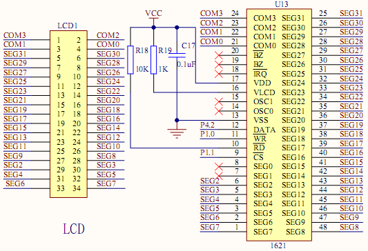
33 Indicator Circuit Diagram TRWS Weighing Indicator Service Manual 11. CIRCUIT DIAGRAM

34 - 34 -
35 - 35 -
36 - 36 -
37 12. DRAWING No Parts Name 1 Display Overlay 2 Display Acrylic Board 3 Up Cover 4 Key Head 5 Main Board 6 M3 Insulation Gasket 7 Cross Round Screws 8 Cross Round Screws 9 Ni-MH Battery 10 Metal Water proof threading Head Component 11 Round Adaptor Base Component 12 Adaptor Rubber Stuff 13 Flat Gasket 14 Battery layering 15 Seal Ring 16 Plastic 17 Bottom Case 18 Gross Round Screws 19 Seal Gasket 20 Cover Gasket 21 M4 Spring washer 22 Hand Tighten Screws 23 Support Frame Bush 24 Support Frame
38 The product range can be summarized as follows: Counting scales for general industrial and warehouse applications. Digital weighing/check-weighing scales. High performance platform scales with extensive software facilities including parts counting, percent weighing etc. Digital electronic scales for medical use. Retail price computing scales. Floor scales. Truck scale. Crane scales. Weighing indicator for platform scales, floor scales and truck scales. Hand push and pull gauge. Customize auto weighing systems. Totalcomp Inc. 99 Reagent Lane Fair Lawn, NJ Tel.: Fax: All information contained within this publication was to the best of our knowledge timely, complete and accurate when issued. However, we are not responsible for misimpressions which may result form the reading of this material.
HIGH PRECISION BALANCE MWP OWNER S MANUAL. MWP-2004-12 ver.1.0
 HIGH PRECISION BALANCE MWP OWNER S MANUAL MWP-2004-12 ver.1.0 INTRODUCTION------------------------------------------------1 1. INSTALLATION---------------------------------------------------2 Unpacking---------------------------------------------------------------2
High precision counting scale. Operation Manual. l RCZ-A Series
 High precision counting scale Operation Manual l RCZ-A Series TABLE OF CONTENTS I. PRECAUTIONS BEFORE USING THE SCALE 1 II. EXPLANATION OF DISPLAY SYMBOLS 2 III. KEYPAD FUNCTIONS 4 IV. OPERATIONS 5 SWITCH
How To Use A Ci 2001A/B (I2) With A Power Supply (I3)
 With A Power Supply (I3)") Weighing Indicator CI-2001A/B OWNER S MANUAL CONTENTS PRECAUTIONS 4 INTRODUCTION 6 THE FEATURES OF CI-2001A/B 6 TECHNICAL SPECIFICATION 7 DIMENSIONS 8 FRONT PANEL(CI-2001A) 9 FRONT PANEL(CI-2001B) 11 REAR
Weighing Indicator CI-2001A/B OWNER S MANUAL CONTENTS PRECAUTIONS 4 INTRODUCTION 6 THE FEATURES OF CI-2001A/B 6 TECHNICAL SPECIFICATION 7 DIMENSIONS 8 FRONT PANEL(CI-2001A) 9 FRONT PANEL(CI-2001B) 11 REAR
BW-500 BED WEIGHER USER MANUAL
 BW-500 BED WEIGHER USER MANUAL 0 1 TABLE OF CONTENTS SPECIFICATION... 3 Equipment... 4 INSTALLING WEIGH BEAM... 5 PREPARATION FOR MEASUREMENT... 6 DP3800 Indicator... 8 POWER SUPPLY... 8 PANEL... 9 KEY
Model 5511 Filler Controller User s Manual Version 1.1 October 2011
 Thompson Scale Company WEIGHING SYSTEMS & PACKAGING MACHINERY CONTROLS 2758 Bingle Road Houston, Texas 77055 Phone: 713/932-9071 Fax: 713/932-9379 www.thompsonscale.com Model 5511 Filler Controller User
PREPARATION. INTERNAL CALIBRATION (No external weight needed.) SPAN CALIBRATION
 SPAN CALIBRATION") Calibration Guide PREPARATION Adventurer Pro Adventurer Pro balances have two calibration methods: Span and Linearity. Some models have Internal Calibration (InCal ) for Span calibration. Ensure that the
Calibration Guide PREPARATION Adventurer Pro Adventurer Pro balances have two calibration methods: Span and Linearity. Some models have Internal Calibration (InCal ) for Span calibration. Ensure that the
SATEX SA 230. - Manual. Weegtechniek holland b.v. PRECISION BALANCE. Patroonsweg 23-27 3892 DA Zeewolde HOLLAND
 - Manual SATEX SA 230 PRECISION BALANCE Weegtechniek holland b.v. Patroonsweg 23-27 3892 DA Zeewolde HOLLAND Tel. + 31 36 522 20 30 Fax. + 31 36 522 20 60 Email [email protected] Website www.satex.nl page
XP Series Balances Operation Manual
 XP Series Balances Operation Manual North and South America: 6542 Fig Street Arvada, Colorado 84 1-8-321-1135 Tel: 33-431-7255 Fax: 33-423-4831 U.K. and Ireland: Denver House, Sovereign Way Trafalgar Business
Troubleshooting and Diagnostics
 Troubleshooting and Diagnostics The troubleshooting and diagnostics guide provides instructions to assist in tracking down the source of many basic controller installation problems. If there is a problem
Adam Equipment. CPWplus. RANGE OF SCALES (P.N. 9009, Rev. C, June 2008)
") Adam Equipment CPWplus RANGE OF SCALES (P.N. 9009, Rev. C, June 2008) Adam Equipment Company 2008 Adam Equipment Company 2008 CONTENTS 1.0 INTRODUCTION...3 2.0 SPECIFICATIONS...4 3.0 INSTALLATION...5 3.1
Adam Equipment CPWplus RANGE OF SCALES (P.N. 9009, Rev. C, June 2008) Adam Equipment Company 2008 Adam Equipment Company 2008 CONTENTS 1.0 INTRODUCTION...3 2.0 SPECIFICATIONS...4 3.0 INSTALLATION...5 3.1
WEA-Base. User manual for load cell transmitters. UK WEA-Base User manual for load cell transmitters Version 3.2 UK
 WEA-Base User manual for load cell transmitters 1 Contents 1. Technical data... 3 2. Assembly... 4 2.1 Power supply... 4 2.2 Load cells... 4 2.3 RS-485... 4 2.4 Relays... 5 2.5 Digital input... 5 2.6 Analogue
OCSM Series. High Resolution Digital Crane Scale. User Guide
 OCSM Series High Resolution Digital Crane Scale Content 1. Safety Guide... 1 2. Features... 1 3. Specifications... 2 4. Capacity... 3 5. Display & Keys... 3 Scale & Remote Keys... 3 Indicators... 4 Message...
CONTIENTS. 1. SPECIFICATIONS (mm)---------- 2 2. CAUTIONS--------------------- 3 3. INSTALLATION INSTRUCTION----- 3
---------- 2 2. CAUTIONS--------------------- 3 3. INSTALLATION INSTRUCTION----- 3") CONTIENTS 2008.4 1. SPECIFICATIONS (mm)---------- 2 2. CAUTIONS--------------------- 3 3. INSTALLATION INSTRUCTION----- 3 4. PANEL LAYOUT----------------- 4 5. BUTTON FUNCTIONS------------- 5 6. OPERATING
CONTIENTS 2008.4 1. SPECIFICATIONS (mm)---------- 2 2. CAUTIONS--------------------- 3 3. INSTALLATION INSTRUCTION----- 3 4. PANEL LAYOUT----------------- 4 5. BUTTON FUNCTIONS------------- 5 6. OPERATING
My Weigh Ultraship Series User Manual
 My Weigh Ultraship Series User Manual Low Batteries, bad battery connections & Faulty AC Adaptors are the #1 cause of Ultraship malfunction and inaccuracy! We test all of our scale returns from consumers.
M O D U L E - 7 E Model CS-Caliprompter Operator s Manual
 O P E R A T I O N S A N D P R O C E D U R E S F O R C S - C A L I P R O M P T E R A N D A C C E S S O R I E S Model CS-Caliprompter Visual screen display allows easy step-by-step operation On-site programming
CASTON. Crane Scale. OWNER S MANUAL (BT Ver.) 9007-CT3-BT33-0 2006. 07
 9007-CT3-BT33-0 2006. 07") Crane Scale CASTON OWNER S MANUAL (BT Ver.) 9007-CT3-BT33-0 2006. 07 CONTENTS PRECAUTIONS 4 OVERALL VIEW 7 SPECIFICATIONS 7 DISPLAY & KEY FUNCTIONS 8 BATTERY USAGE 9 USE OF BATTERY CHARGER 9 FUNCTIONS
Crane Scale CASTON OWNER S MANUAL (BT Ver.) 9007-CT3-BT33-0 2006. 07 CONTENTS PRECAUTIONS 4 OVERALL VIEW 7 SPECIFICATIONS 7 DISPLAY & KEY FUNCTIONS 8 BATTERY USAGE 9 USE OF BATTERY CHARGER 9 FUNCTIONS
PPM Users Manual Signature Software 01-12-00
 PPM Users Manual Signature Software 0-2-00 PPM User Manual /8/02 Software Versions: 0.0.27 Contents. Introduction 2 2. Parameters 3 2. Overload Limit...4 2.2 Relative Upper Limit...4 2.3 Relative Lower
OEM Manual MODEL 2350 ELECTRONIC DUAL CYLINDER SCALE
 OEM Manual MODEL 2350 ELECTRONIC DUAL CYLINDER SCALE Scaletron Industries, Ltd. Bedminster Industrial Park 53 Apple Tree Lane P.O. Box 365 Plumsteadville, PA 18949 USA Toll Free: 1-800-257-5911 (USA &
ELECTRONIC COUNTING SCALE. Operation Manual. l JCS- A SERIES
 ELECTRONIC COUNTING SCALE Operation Manual l JCS- A SERIES CONTENTS I. Specification:... II. Operation:... III. Weight calibration:... IV. RS232 transmission confer Data format (optional) V. Regular trouble
Digital Weight Indicator Setup / Operation Manual
 Digital Weight Indicator Setup / Operation Manual Revision 1.0 July 8, 2009 i TABLE OF CONTENTS Page INTRODUCTION... 1 FCC NOTE... 1 INSTALLATION... 1 PREPARATION... 1 CONNECTIONS... 2 CONNECTING THE WEIGH
How To Power A Power Control On An Ip40 (Ipl) With A Power Supply (Iplug) With An Ip20 Controller (Iphones) With Power Control (Power Control) With No Antenna) With The Ip20 (Power)
 With A Power Supply (Iplug) With An Ip20 Controller (Iphones) With Power Control (Power Control) With No Antenna) With The Ip20 (Power)") MODEL NUMBER: ISC910-1-0-GB-XX ISC911-5-0-GB-XX IXP20 CONTROLLER SPECIFICATIONS Working Environment Plastic Housing... Power ImproX IXP20 Controller INSTALLATION MANUAL Designed to work in an indoor (dry)
MODEL NUMBER: ISC910-1-0-GB-XX ISC911-5-0-GB-XX IXP20 CONTROLLER SPECIFICATIONS Working Environment Plastic Housing... Power ImproX IXP20 Controller INSTALLATION MANUAL Designed to work in an indoor (dry)
HCS-3300/3302/3304 USB Remote Programmable Laboratory Grade Switching Mode Power Supply
 1. INTRODUCTION HCS-3300/3302/3304 USB Remote Programmable Laboratory Grade Switching Mode Power Supply User Manual This family of efficient, upgraded SMPS with small form factor, auto cross over CV CC,
PA Series Precision Analytical Balances USER MANUAL
 PA Series Precision Analytical Balances USER MANUAL (Software Revision: 2.35) Page 2 of 32 Page 3 of 32 CONTENTS 1.0 INTRODUCTION...4 2.0 TECHNICAL SPECIFICATIONS...5 3.0 UNPACKING THE BALANCE...6 4.0
1. SAFETY INFORMATION
 RS-232 Sound Level Meter 72-860A INSTRUCTION MANUAL www.tenma.com 1. SAFETY INFORMATION Read the following safety information carefully before attempting to operate or service the meter. Use the meter
Operating instructions Platform/floor scales
 KERN & Sohn GmbH Ziegelei 1 D-72336 Balingen email: [email protected] Phone: +49-[0]7433-9933-0 Fax: +49-[0]7433-9933-149 Internet: www.kern-sohn.com Operating instructions Platform/floor scales KERN
INDUSTRIAL INDICATOR. 200 Series OPERATING MANUAL - 1 -
 INDUSTRIAL INDICATOR NT-20 200 Series OPERATING MANUAL - 1 - Table of Contents 0. Precaution ------------------ 3 1. Introduction ------------------ 4 2. Features & Main Function ------------------ 5 3.
Troubleshooting Tips Lifestyle SA-2 & SA-3 Amplifier. Troubleshooting Tips
 Troubleshooting Tips Lifestyle SA-2 & SA-3 Amplifier Refer to the Lifestyle SA-2 & SA-3 Amplifier service manuals, part number 271720 for schematics, PCB layouts and parts lists. Preventative Repair Measures
Manual Ranging MultiMeter
 Owner s Manual Manual Ranging MultiMeter Model 82345 CAUTION: Read, understand and follow Safety Rules and Operating Instructions in this manual before using this product.! Safety! Operation! Maintenance!
PTU Series Ultrahigh-Purity Pressure Transducers
 PTU Series UltrahighPurity Pressure Transducers User s Manual The Swagelok PTU series pressure transducer provides electronic monitoring of system pressure for ultrahighpurity applications. The PTU series
4-Channel Thermometer / Datalogger
 USER GUIDE 4-Channel Thermometer / Datalogger RTD and Thermocouple Inputs Model SDL200 Introduction Congratulations on your purchase of the Extech SDL200 Thermometer, an SD Logger Series meter. This meter
IDEAL INDUSTRIES, INC. TECHNICAL MANUAL MODELS: 61-763 61-765
 IDEAL INDUSTRIES, INC. TECHNICAL MANUAL MODELS: 61-763 61-765 The Service Information provides the following information: Precautions and safety information Specifications Performance test procedure Calibration
Auto-ranging Digital Multimeter 52-0052-2 INSTRUCTION MANUAL
 Auto-ranging Digital Multimeter 52-0052-2 INSTRUCTION MANUAL WARNING: READ AND UNDERSTAND THIS MANUAL BEFORE USING YOUR MULTIMETER. FAILURE TO UNDERSTAND AND COMPLY WITH WARNINGS AND OPERATING INSTRUCTIONS
Series 6000 Torque measured metal bellow coupling
 Properties Free of float metal bellow coupling with integrated torque measurement Non-contact measurement system, high robustness High torsional stiffness Limited torque of inertia Performance Measurement
AutoRanging Digital MultiMeter
 Owner's Manual AutoRanging Digital MultiMeter Model No. 82139 CAUTION: Read, understand and follow Safety Rules and Operating Instructions in this manual before using this product. Safety Operation Maintenance
User Operation Manual
 A Higher Level of Precision A Higher Level of Performance Intell-Count Dual Channel Counting Scale QHD Series User Operation Manual - 2 - January 2009 CONTENTS SECTION 1 INTRODUCTION......1 SECTION2 TECHNICAL
SERVICE MANUAL Valor 3000 SCALES
 SERVICE MANUAL Valor 3000 SCALES Ohaus Corporation, 7 Campus Drive, Suite 310, Parsippany, NJ 07054 (973) 377-9000 SERVICE MANUAL Valor 3000 SCALES The information contained in this manual is believed
Keep it Simple Timing
 Keep it Simple Timing Support... 1 Introduction... 2 Turn On and Go... 3 Start Clock for Orienteering... 3 Pre Start Clock for Orienteering... 3 Real Time / Finish Clock... 3 Timer Clock... 4 Configuring
Digital Indicator. Revision 1.4 September 24, 2004. 1999-2004 Transcell Technology, Inc. Contents subject to change without notice.
 TI-1600 Series Digital Indicator Setup / Operation Manual Revision 1.4 September 24, 2004 1999-2004 Transcell Technology, Inc. Contents subject to change without notice. Transcell Technology, Inc. 975
BROOKFIELD MODEL VTE250 ELECTRIC VISCOSEL PROCESS VISCOMETER. Installation, Operation, and Maintenance Instructions. Manual No.
 BROOKFIELD MODEL VTE250 ELECTRIC VISCOSEL PROCESS VISCOMETER Installation, Operation, and Maintenance Instructions Manual No. M06-512 SPECIALISTS IN THE MEASUREMENT AND CONTROL OF VISCOSITY BROOKFIELD
AC-115 Compact Networked Single Door Controller. Installation and User Manual
 AC-115 Compact Networked Single Controller Installation and User Manual December 2007 Table of Contents Table of Contents 1. Introduction...5 1.1 Key Features... 6 1.2 Technical Specifications... 7 2.
Programming and Using the Courier V.Everything Modem for Remote Operation of DDF6000
 Programming and Using the Courier V.Everything Modem for Remote Operation of DDF6000 1.0 Introduction A Technical Application Note from Doppler System July 5, 1999 Version 3.x of the DDF6000, running version
Instruction Manual Crane Scales PCE-HS Series
 PCE Americas Inc. 711 Commerce Way Suite 8 Jupiter FL-33458 USA From outside US: +1 Tel: (561) 320-9162 Fax: (561) 320-9176 [email protected] PCE Instruments UK Ltd. Units 12/13 Southpoint Business
Instruction Manual. 2in1 LAN Tester & Multimeter. Model: LA-1011
 Instruction Manual 2in1 LAN Tester & Multimeter Model: LA-1011 1 Contents Introduction... Features... Safety Precautions.. Meter Description... Electrical Specification... Operation.. AutoRanging Multimeter.
How To Program An Autodialer
 GJD HYL005 GSM Autodialer Instruction Manual Please read these instructions before you start the installation Features: LCD display. Programmable 9 x 32 digit phone numbers for each trigger. 10 second
INDUSTRIAL INSTRUMENTATION
 INDUSTRIAL INSTRUMENTATION Table of contents. Table of contents.... 2 Explanation of production screen.... 3 Wiring connection for Flex-MF model Flex.... 4 Wiring connection for Flex-MF model Flex-2100....
Configuring the Siemens TC35 modems for use with the MI2292
 Configuring the Siemens TC35 modems for use with the MI2292 The following instruction describe how to set up GSM communication between an MI2292 Power Quality Analyser Plus and a computer 1. Equipment
OPERATION MANUAL MARSDEN-200 PLEASE TAKE THE TIME TO READ THESE INSTRUCTIONS BEFORE STARTING TO USE THE SCALES
 OPERATION MANUAL MARSDEN-200 PLEASE TAKE THE TIME TO READ THESE INSTRUCTIONS BEFORE STARTING TO USE THE SCALES 1 TABLE OF CONTENTS POWER SUPPLY... 3 SPECIFICATIONS... 3 MAINATENANCE AND GENERAL CARE........
HP UPS R1500 Generation 3
 HP UPS R1500 Generation 3 Installation Instructions Part Number 650952-001 NOTE: The rating label on the device provides the class (A or B) of the equipment. Class B devices have a Federal Communications
GAUGEMASTER PRODIGY EXPRESS
 GAUGEMASTER PRODIGY EXPRESS DCC01 USER MANUAL Version 1.1 2011 T A B L E O F C O N T E N T S 1 Getting Started Introduction Specifications and Features Quick Start Connecting to Your Layout Running a Loco
LG Air Conditioning Multi F(DX) Fault Codes Sheet. Multi Split Units
 Fault Codes Sheet. Multi Split Units") Multi Split Units If there is a fault on any LG Multi unit, an Error mark is indicated on the display window of the indoor unit, wired-remote controller, and LED s of outdoor unit control board. A two
Multi Split Units If there is a fault on any LG Multi unit, an Error mark is indicated on the display window of the indoor unit, wired-remote controller, and LED s of outdoor unit control board. A two
HT580 User Reference Guide. Version 1.0
 Version 1.0 NOTICE 1. Li-Ion Battery Pack The HT580 Portable Terminal and the Li-Ion Battery Pack are packaged separately. You will have to install the Battery Pack when you receive your terminal. Please
TI-500E Plus DIGITAL WEIGHT INDICATOR Setup / Operation Manual
 TI-500E Plus DIGITAL WEIGHT INDICATOR Setup / Operation Manual Revision 1.0 975 Deerfield Parkway Buffalo Grove, IL 60089 January 28, 2008 Tel (847) 419-9180 Fax (847) 419-1515 http://www.transcell.net
PYRODIGITAL CONSULTANTS PD Firing Module Continuity Reader
 Firmware Version 2.03 Page 1 of 22 1 Features... 5 2 Warning!... 6 3 Intended Purpose for PD Firing Module Reader... 7 4 Primary Controls:... 8 4.1 On/Off... 8 4.2 Measure - INFORMATION... 8 4.3 Find -
Instruction Manual FL
 3. Operation Overview The most common used features (such as displaying force, peak hold, zero and changing of displayed units) can all be done by pressing a single dedicated key identified on the front
Manual for Fire Suppression & Methane Detection System
 Manual for Fire Suppression & Methane Detection System Fogmaker North America Post address: 150 Gordon Dr Exton, PA 19341 Delivery address: 150 Gordon Dr Exton, PA 19341 Tel: 610-265-3610 Fax: 610-265-8327
User Guide. Heavy Duty Dissolved Oxygen Meter. Model 407510
 User Guide Heavy Duty Dissolved Oxygen Meter Model 407510 Introduction Congratulations on your purchase of Extech's Heavy Duty Dissolved Oxygen / Temperature Meter which simultaneously displays Dissolved
ANALYTICAL BALANCE OPERATION MANUAL. (FA/JA Series)
") ANALYTICAL BALANCE OPERATION MANUAL (FA/JA Series) CONTENT I. II. III. IV. V. VI. VII. Brief Introduction...1 Main Technical Specifications...1 Drawings for Balance Installation...2 Operation...3 Maintenance
ANALYTICAL BALANCE OPERATION MANUAL (FA/JA Series) CONTENT I. II. III. IV. V. VI. VII. Brief Introduction...1 Main Technical Specifications...1 Drawings for Balance Installation...2 Operation...3 Maintenance
Precision Miniature Load Cell. Models 8431, 8432 with Overload Protection
 w Technical Product Information Precision Miniature Load Cell with Overload Protection 1. Introduction The load cells in the model 8431 and 8432 series are primarily designed for the measurement of force
GSM AD05 Slave GSM Auto Dialer- Instruction Manual
 GSM AD05 Slave GSM Auto Dialer- Instruction Manual Please read these instructions before you start the installation Features LCD display Programmable 9 x 32 digit phone numbers for each trigger. 10 second
FAQ s on Siemens Magmeters
 FAQ s on Siemens Magmeters 1. The cables for the coils and electrodes for the magmeters look the same. Does it matter which cable is used for coils and which one is used for the electrodes? Both cables
Ground Resistance Clamp On Tester
 USER MANUAL Ground Resistance Clamp On Tester MODEL 382357 Introduction Congratulations on your purchase of Extech s 382357 Ground Resistance Tester. This Clamp on device allows the user to measure ground
OCS-XZ-C Series User s Guide. OCS-XZ Series Electronic Crane Scale. User s Guide - 1 -
 OCS-XZ Series Electronic Crane Scale User s Guide - 1 - Table of Contents 1. Brief Introduction 2. Features & Specifications 3. Functions of Key Pad & Indicators 4. Basic Operations Power ON Initial on
Subminiature Load Cell Model 8417
 w Technical Product Information Subminiature Load Cell 1. Introduction... 2 2. Preparing for use... 2 2.1 Unpacking... 2 2.2 Using the instrument for the first time... 2 2.3 Grounding and potential connection...
CAD-05 Kit GSM Auto Dialer. Owner s Manual
 CAD-05 Kit GSM Auto Dialer Owner s Manual CAD-05 Kit Manual.indd 1 Warnings: This device complies with Part 15 of the FCC rules, Operation of this device is subject to the following conditions: 1. This
8142PRO (PR08) Industrial Terminal Service Manual
 Industrial Terminal Service Manual") 8142PRO (PR08) Industrial Terminal Service Manual 1 1. Introduction This manual describes the 8142Pro+ dual display scale terminal (PRGN-XXX8), which is tailor designed to meet the vehicle and floor scale
8142PRO (PR08) Industrial Terminal Service Manual 1 1. Introduction This manual describes the 8142Pro+ dual display scale terminal (PRGN-XXX8), which is tailor designed to meet the vehicle and floor scale
BlueSolar Pro Remote Panel For BlueSolar PWM-Pro charge controllers 12/24V 5, 10, 20, 30A Article number SCC900300000
 Manual EN BlueSolar Pro Remote Panel For BlueSolar PWM-Pro charge controllers 12/24V 5, 10, 20, 30A Article number SCC900300000 Contents EN 1.Important safety instructions... 2 2. Installation... 2 3.Product
UT202A Operating Manual. Contents
 Title Contents Page Overview Unpacking Inspection Safety Information Rules for Safe Operation International Electrical Symbols The Meter Structure Functional Buttons and auto power off Display Symbols
Setting Up the ZigBee Ethernet Gateway
 Setting Up the ZigBee Ethernet Gateway MAN-01-00030-1.4 This manual describes how to install and set up ZigBee communication between a SolarEdge device (Inverters or Safety and Monitoring Interface) and
GSM Alarm System User Manual
 GSM Alarm System User Manual For a better understanding of this product, please read this user manual thoroughly before using it. Quick Guider After getting this alarm system, you need to do the following
ACS-3S/NEW SU ELECTRONIC SINGLE/DUAL DISPLAY WEIGHING/COUNTING SCALE USER MANUAL
 ACS- SU ELECTRONIC SINGLE/DUAL DISPLAY WEIGHING/COUNTING SCALE USER MANUAL Thank you for choosing our ACS-3S / NEW SU single/double side display electronic waterproof weighing/counting scale. The new SU
CQ-Series. User Manual. American Weigh Scales, Inc. CQ-350 (350x0.1g) CQ-500 (500x0.1g) Digital Pocket Scale . = + CALC AC CE % TARE OFF ON MC MR CALI
 CQ-500 (500x0.1g) Digital Pocket Scale . = + CALC AC CE % TARE OFF ON MC MR CALI") American Weigh Scales, Inc. CQ-Series Digital Pocket Scale 7 4 1 0. 8 9 5 6 2 3 x = - CALI + CALC MODE M CAL AC CE % TARE OFF ON MC MR CQ-350 (350x0.1g) CQ-500 (500x0.1g) User Manual CQ-Series Manual Thank
American Weigh Scales, Inc. CQ-Series Digital Pocket Scale 7 4 1 0. 8 9 5 6 2 3 x = - CALI + CALC MODE M CAL AC CE % TARE OFF ON MC MR CQ-350 (350x0.1g) CQ-500 (500x0.1g) User Manual CQ-Series Manual Thank
e-4 AWT07MLED 7 Q TFT LCD MONITOR (LED Backlighted) USER MANUAL
 USER MANUAL") Thank you for purchasing our product. Please read this User s Manual before using the product. Change without Notice AWT07MLED 7 Q TFT LCD MONITOR (LED Backlighted) USER MANUAL e-4 SAFETY PRECAUTIONS Federal
Thank you for purchasing our product. Please read this User s Manual before using the product. Change without Notice AWT07MLED 7 Q TFT LCD MONITOR (LED Backlighted) USER MANUAL e-4 SAFETY PRECAUTIONS Federal
LDG DTS-4/4R Desktop Coaxial Switch / Remote
 LDG DTS-4/4R Desktop Coaxial Switch / Remote LDG Electronics 1445 Parran Road, PO Box 48 St. Leonard MD 20685-2903 USA Phone: 410-586-2177 Fax: 410-586-8475 [email protected] www.ldgelectronics.com
Troubleshooting and Diagnostics
 Troubleshooting and Diagnostics The troubleshooting and diagnostics guide provides instructions to assist in tracking down the source of many basic controller installation problems. If there is a problem
OCS-S High Resolution Digital Crane Scale
 OCS-S High Resolution Digital Crane Scale Content 1. Safety Guide... 1 2. Features... 1 3. Specifications... 2 4. Capacity... 2 5. Dimension & Weight... 3 6. Display & Keys... 4 Scale Keys... 4 Indicators...
Table of Contents. The Basics of Electricity 2. Using a Digital Multimeter 4. Testing Voltage 8. Testing Current 10. Testing Resistance 12
 Table of Contents The Basics of Electricity 2 Using a Digital Multimeter 4 IDEAL Digital Multimeters An Introduction The Basics of Digital Multimeters is designed to give you a fundamental knowledge of
Before installation it is important to know what parts you have and what the capabilities of these parts are.
 INSTALLATION GUIDE Before installation it is important to know what parts you have and what the capabilities of these parts are. The Recon XZT is the smallest and most powerful gauge of its kind. With
LUCCI AIRFUSION QUEST II CEILING FAN
 LUCCI AIRFUSION QUEST II CEILING FAN WITH IR REMOTE INSTALLATION OPERATION MAINTENANCE WARRANTY INFORMATION CAUTION READ INSTRUCTIONS CAREFULLY FOR SAFE INSTALLATION AND FAN OPERATION. V1.0 QUEST II IR
HIGH PRECISION WEIGHING SCALE. Operation Manual. l RCZ-B Series
 HIGH PRECISION WEIGHING SCALE Operation Manual l RCZ-B Series CONTENTS. Specification:. Keyboard instruction:... Operation:.. IV. Alarm indication:. V.RS232 transmission method (optional):. . Specification:
GSM Autodialer Professional GJD700 Speech & Text Autodialer
 Text Edit message GSM Autodialer Professional GJD700 Speech & Text Autodialer Introduction The GSM Autodialer Professional works in conjunction with standard alarm systems and makes use of your preferred
RS232C < - > RS485 CONVERTER S MANUAL. Model: LD15U. Phone: 91-79-4002 4896 / 97 / 98 (M) 0-98253-50221 www.interfaceproducts.info
 0-98253-50221 www.interfaceproducts.info") RS232C < - > RS485 CONVERTER S MANUAL Model: LD15U INTRODUCTION Milestone s model LD-15U is a RS232 to RS 485 converter is designed for highspeed data transmission between computer system and or peripherals
RS232C < - > RS485 CONVERTER S MANUAL Model: LD15U INTRODUCTION Milestone s model LD-15U is a RS232 to RS 485 converter is designed for highspeed data transmission between computer system and or peripherals
8 Channel Status Input Panel model SIP-8
 Description The Sine Systems model SIP-8 Status Input Panel is to be used with the RFC-1/B Remote Facilities Controller. It consists of a long PC board mounted on a 1.75 inch (1U) rack panel. The SIP-8
Back-UPS Pro 1300/1500 Installation and Operation
 Back-UPS Pro 1300/1500 Installation and Operation Inventory Safety Do not install the Back-UPS in direct sunlight, in excessive heat, humidity, or in contact with fluids. Connect the battery bu059a bu058a
M 140i. Multifunction Calibrator. Operation Manual
 M 140i Multifunction Calibrator Operation Manual M-140i Multifunction Calibrator MEATEST, s.r.o. 2 Operation Manual v33 MEATEST, s.r.o. M-140i Multifunction Calibrator Content Operation Manual... 1 Basic
SPY-BATT Battery Tutor Device Installation Manual Rev. 1.1-07/04/2016
 SPY-BATT Battery Tutor Device Installation Manual Rev. 1.1-07/04/2016 1. GENERAL DESCRIPTION The SPY-BATT is a device that allows to monitor the state of your battery. The SPY-BATT stores over time the
RS Stock No. 724-4207 Instruction Manual RS-1340 Hot Wire Anemometer
 RS Stock No. 724-4207 Instruction Manual RS-1340 Hot Wire Anemometer EN FR IT DE ES CONTENTS / EN Title CONTENTS Page 1. SAFETY INFORMATION...1 2. INTRODUCTION...2 3. SPECIFICATIONS...3 4. PARTS & CONTROLS...4
12 Volt 30 Amp Digital Solar Charge Controller
 12 Volt 30 Amp Digital Solar Charge Controller User s Manual WARNING Read carefully and understand all INSTRUCTIONS before operating. Failure to follow the safety rules and other basic safety precautions
Digital I/O: OUTPUT: Basic, Count, Count+, Smart+
 Digital I/O: OUTPUT: Basic, Count, Count+, Smart+ The digital I/O option port in the 4-Series provides us with 4 optically isolated inputs and 4 optically isolated outputs. All power is supplied externally.
Firmware version: 1.10 Issue: 7 AUTODIALER GD30.2. Instruction Manual
 Firmware version: 1.10 Issue: 7 AUTODIALER GD30.2 Instruction Manual Firmware version: 2.0.1 Issue: 0.6 Version of the GPRS transmitters configurator: 1.3.6.3 Date of issue: 07.03.2012 TABLE OF CONTENTS
New GSM Alarm System. User s Manual. Profile For a better understanding of this product, please read this user manual thoroughly before using it.
 New GSM Alarm System User s Manual Profile For a better understanding of this product, please read this user manual thoroughly before using it. Chapter 1. Features Chapter 2. Alarm Host Introduction Chapter
GSM HOME SECURITY SYSTEM
 Cell /Mobile phone home security system GSM HOME SECURITY SYSTEM Model : GSM-120 TABLE OF CONTENTS 1. FEATURES... 1 2. APPLICATION... 2 3. SPECIFICATIONS... 3 4. FRONT PANEL & LAYOUT DESCRIPTION...6 5.
User s Manual AURORA 1.2K/2.2K
 User s Manual AURORA 1.2K/2.2K Uninterruptible Power System Safety CAUTION This UPS utilizes voltages that may be hazardous. Do not attempt to disassemble the unit. The unit contains no user serviceable
Radio BMR100 INSTRUCTION MANUAL. ENGLISH (Original instructions)
") ENGLISH (Original instructions) INSTRUCTION MANUAL Radio BMR00 WARNING: For your personal safety, READ and UNDERSTAND before using. SAVE THESE INSTRUCTIONS FOR FUTURE REFERENCE. Symbols The following show
ENGLISH (Original instructions) INSTRUCTION MANUAL Radio BMR00 WARNING: For your personal safety, READ and UNDERSTAND before using. SAVE THESE INSTRUCTIONS FOR FUTURE REFERENCE. Symbols The following show
4.3-inch Back-Up Camera
 TM 4.-inch Back-Up Camera Model No.: PKC0BU4 Owner s Manual and Warranty Information Read these instructions completely before using this product. Retain this Owner s Manual for future reference. INTRODUCTION
User's Guide. Integrating Sound Level Datalogger. Model 407780. Introduction
 User's Guide 99 Washington Street Melrose, MA 02176 Phone 781-665-1400 Toll Free 1-800-517-8431 Visit us at www.testequipmentdepot.com Back to the Extech 407780 Product Page Integrating Sound Level Datalogger
How To Use A Power Supply Unit (Upu)
") BRAVER UPS (Uninterruptible Power System) User s Manual Safety CAUTION! This UPS utilizes voltages that may be hazardous. Do not attempt to disassemble the unit. The unit contains no user replaceable parts.
BRAVER UPS (Uninterruptible Power System) User s Manual Safety CAUTION! This UPS utilizes voltages that may be hazardous. Do not attempt to disassemble the unit. The unit contains no user replaceable parts.
VOLTAGE/CURRENT CALIBRATOR ISO-TECH ILC-421
 VOLTAGE/CURRENT CALIBRATOR ISO-TECH ILC-421 TABLE OF CONTENTS 1. FEATURES... 1 2. SPECIFICATIONS... 1 2-1 General Specifications...1 2-2 Electrical Specifications... 2 3. FRONT PANEL DESCRIPTION... 4 3-1
CAUTION OPC-LM1-IL. Option Card for Encoder of Line Driver Output. Instruction Manual
 Instruction Manual OPC-LM1-IL Option Card for Encoder of Line Driver Output CAUTION Deliver this instruction manual without fail to those who actually operate the equipment. Read this operation manual
Vroom Hardware manual ver. 1.00 Code 114VROOHWE00. Vroom CANBUS USER INTERFACE WITH LCD GRAPHIC DISPLAY AND WITH TEMPERATURE AND HUMIDITY SENSOR
 Vroom CANBUS USER INTERFACE WITH LCD GRAPHIC DISPLAY AND WITH TEMPERATURE AND HUMIDITY SENSOR ENGLISH HARDWARE MANUAL ver. 1.00 CODE 114VROOHWE00 page 1 of 22 Important Important Read these instructions
DAB1001. Wireless Digital Radio Interface. Installation & User Guide
 DAB1001 Wireless Digital Radio Interface Installation & User Guide Contents Contents... 2 Introduction... 3 Contents of Package... 4 Installation... 5 Product Overview... 5 Installation Procedure... 5