Single-core power cable. 18/30 (36) kv Conductor material 1x630 mm 2 Insulation material. HES HACILAR ELEKTRİK SAN. VE TİC. A.Ş.
|
|
|
- Lesley Stafford
- 7 years ago
- Views:
Transcription
1 TIC TYPE TEST CERTIFICATE OF COMPLETE TYPE TESTSS OBJECT TYPE Single-core power cable N2XSYR(A)Y Rated voltage, U 0/U (U m) Conductor cross-section 18/30 (36) kv Conductor material 1x630 mm 2 Insulation material Cu XLPE MANUFACTURER CLIENT TESTED BY DATE OF TESTS HES HACILAR ELEKTRİK SAN. VE TİC. A.Ş., Kayseri, Turkey HES HACILAR ELEKTRİK SAN. VE TİC. A.Ş., Kayseri, Turkey KEMA HIGH-VOLTAGE LABORATORY Arnhem, the Netherlands 7 May to 17 August 2012 The object, constructed in accordance with the description, drawings and photographs incorporated in this Certificate, has been subjected to the series of proving tests in accordance with IEC This Type Test Certificate has been issued by KEMA following exclusively the STL Guides. The results are shown in the record of Proving Tests and the oscillograms attached hereto. The values obtained and the general performance are considered to comply with the above Standard and to justify the ratings assigned by the manufacturer as listed on pages 4 and 5. The Certificate applies only to the object tested. The responsibility for conformity of any object having the same designations with that tested rests with the Manufacturer. This Certificate consists of 35 pages in total. Copyright: Only integral reproduction of this Certificate is permitted without written permission from KEMA. Electronic copies in e.g. PDF-format or scanned version of this Certificate may be available and have the status for information only. The sealed and bound version of the Certificate is the only valid version. KEMA Nederland B.V. S.A.M. Verhoeven Director Testing, Inspections & Certification The Netherlands Arnhem, 4 February 2013

2 -2- TIC TABLE OF CONTENTS TABLE OF CONTENTS Identification of the test object Description of the test object List of documents General information The tests were witnessed by The tests were carried out by Subcontracting Purpose of the test Measurement uncertainty Applicable standards Electrical type tests General Tests at elevated conductor temperature Bending test followed by a partial discharge test Bending test Partial discharge test Tan δ measurement Heating cycle test followed by a partial discharge test Heating cycle test Partial discharge test Impulse test followed by a voltage test Impulse test Voltage test Voltage test for 4 hours Resistivity of semi-conducting screens Non-electrical type tests Measurement of thickness of insulation Measurement of thickness of non-metallic sheaths Tests for determining the mechanical properties of the insulation before and after ageing Tests for determining the mechanical properties of non-metallic sheaths before and after ageing Additional ageing test on pieces of completed cable Loss of mass test on PVC sheaths of type ST Pressure test at high temperature on non-metallic sheaths Test on PVC insulation and sheaths at low temperatures Test for resistance of PVC insulation and sheaths to cracking (heat shock test)...28

3 -3- TIC Hot set test for XLPE insulation Water absorption test on insulation Flame spread test on single cables Shrinkage test for XLPE insulation Verification of cable construction...33 APPENDIX A MEASUREMENT UNCERTAINTIES APPENDIX B MANUFACTURER S DRAWING(S)/DATA SHEET... 35

4 -4- TIC IDENTIFICATION OF THE TEST OBJECT 1.1 Description of the test object Manufacturer HES HACILAR ELEKTRİK SAN. VE TİC. A.Ş., Kayseri, Turkey Type N2XSYR(A)Y Year of manufacture 2012 Sampling procedure by the manufacturer Quantity submitted 50 m Rated voltage, U 0 /U (U m ) 18/30 (36) kv No. of cores (core identification) 1 Marking on the cable HES (N)2XSYR(A)Y 1x630RM/35mm 2 18/30 kv IEC Conductor - material copper - cross-section 630 mm 2 - nominal diameter 30 mm - type stranded and compacted - maximum conductor temperature 90 C in normal operation Conductor screen - material semi-conducting XLPE - nominal thickness 0,6 mm - material designation LE manufacturer Borealis Insulation - material XLPE - nominal thickness 8,0 mm - material designation 4201 R - manufacturer Borealis Insulation screen - material semi-conducting XLPE - strippable no - nominal thickness 0,6 mm - material designation LE manufacturer Borealis

5 -5- TIC Metallic screen - material copper - number and nominal diameter of wires 96 wires of Ø 0,66 mm - nominal thickness and width of tape 20 x 0,1 mm - nominal thickness/diameter Ø 0,51 mm Binder/Filling material Inner / Separation sheath - material PVC (Y), type ST 2 - nominal thickness 1,6 mm - material supplier HES CABLE Compound (for s-pvc resin was supplied by Petkim) Metallic armour - material aluminium wires - number and nominal diameter of wires 68 wires of Ø 2,5 mm - nominal thickness and width of tape 60 x 0,1 mm - material supplier HES Copper and Aluminum Production Plant Oversheath - material PVC (Y), type ST 2 - nominal thickness 3,0 mm - nominal overall diameter of cable 65 ± 2 mm - manufacturer HES CABLE Compound (for s-pvc resin was supplied by Petkim) - colour red Longitudinally watertightness - along insulation screen not claimed - along the conductor not claimed Fire retardant (IEC ) yes
, type ST 2 - nominal thickness 3,0 mm - nominal overall diameter of cable 65 ± 2 mm - manufacturer HES CABLE Compound (for s-pvc resin was supplied by Petkim) -")
6 -6- TIC List of documents The manufacturer has guaranteed that the object submitted for tests has been manufactured in accordance with the following document. KEMA has verified that this document adequately represents the object tested. The following document is included in this Certificate: drawing no./ document no. revision date title (N)2XSYR(A)Y 1X /30 KV 2 20/10/2012 -

7 -7- TIC GENERAL INFORMATION 2.1 The tests were witnessed by The tests were not witnessed. 2.2 The tests were carried out by Name Mr. S. Smeenk Mr. B. Peters Mr. J. Stankovic Company KEMA Nederland B.V., Arnhem, the Netherlands 2.3 Subcontracting The following tests were subcontracted to DNV KEMA Cleaner Energy Generation: - measurement of resistivity of semi conducting screens in accordance with clause of IEC non-electrical type tests in accordance with clause 19 of IEC , with exception of water penetration test - verification of cable construction in accordance with clauses 5-14 of IEC Purpose of the test Purpose of the test was to verify whether the material complies with the specified requirements. 2.5 Measurement uncertainty A table with measurement uncertainties is enclosed in appendix A. Unless otherwise indicated in the report, the measurement uncertainties of the results presented are as indicated in this table. 2.6 Applicable standards When reference is made to a standard and the date of issue is not stated, this applies to the latest issue, including amendments, which have been officially published prior to the date of the tests.

8 -8- TIC ELECTRICAL TYPE TESTS 3.1 General Tests at elevated conductor temperature For the tests with the cable at elevated temperature, a reference loop for temperature control of the conductor was installed. The reference cable was cut from the total cable length submitted by the client intended for the type test. This reference loop was installed close to the main loop in order to create the same environmental conditions as for the test loop. The heating currents in both the reference loop and the test loop were kept equal at all times, thus the conductor temperature of the reference loop is representative for the conductor temperature of the test loop. All three phases of both the reference loop and the test loop carried the same level three-phase current. Annex A, method 1 of IEC was used as a guide.

9 -9- TIC Bending test followed by a partial discharge test Bending test Standard IEC , clause Test date 7 May 2012 Environmental conditions Ambient temperature 15 C Temperature of test object 15 C Characteristic test data Bending diameter: Three core cable ( others ) 15(d + D) ± 5% measured outer diameter of cable D (mm) measured diameter of cable conductor d (mm) required bending diameter D r (m) 65 29,9 1,80 D r 1,99 1,80 diameter of test cylinder D t (m) Procedure The test sample shall be bent around a test cylinder at ambient temperature for at least one complete turn. It shall then be unwound and repeated, except that the sample shall be bent in the reverse direction without axial rotation. This cycle of operation shall be carried out three times. Observation The test was carried out successfully.
 65 29,9 1,80 D r 1,99 1,80 diameter of test cylinder D t (m) Procedure The test sample shall be bent around a test cylinder at ambient temperature for at least one complete")
10 -10- TIC Partial discharge test Standard IEC , clause Test date 24 May 2012 Environmental conditions Ambient temperature 21 C Temperature of test object 21 C Characteristic test data Circuit direct Calibration 5 pc Noise 1 pc Sensitivity 2 pc Required sensitivity 5 pc Bandwidth khz Test frequency 50 Hz Coupling capacitor 2600 pf core voltage applied, 50 Hz duration partial discharge level... x U 0 (kv) (s) (pc) , ,73 31,1 - not detectable , ,73 31,1 - not detectable , ,73 31,1 - not detectable Requirement There shall be no detectable discharge exceeding the declared sensitivity from the test object at 1,73U 0.
 (s) (pc) 1 2 36,0 10-1 1,73 31,1 - not detectable 2 2 36,0 10-2 1,73 31,1 - not detectable 3 2 36,0 10-3 1,73 31,1 - not detectable Requirement There shall be")
11 -11- TIC Tan δ measurement Standard IEC , clause Test date 25 May 2012 Environmental conditions Ambient temperature 20 C Temperature of test object 20 C Characteristic test data Length of test object 13,39 m Standard capacitor 100 pf core voltage applied, 50 Hz core capacitance 1) tan δ (kv) (µf/km) 1 4, ,56 x ) for information only Requirement The measured value shall not be higher than 40x10-4.
 (µf/km) 1 4,2 292 0,56 x 10⁻⁴ 1) for information only Requirement The measured value shall not be higher")
12 -12- TIC Heating cycle test followed by a partial discharge test Heating cycle test Standard IEC , clause Test period 29 May to 10 June 2012 Environmental conditions Ambient temperature C Characteristic test data Stabilized temperature 97 C no. of heating cycles required stable conductor temperature heating current during stable condition heating per cycle cooling per cycle ( C) (A) total duration (h) duration of conductor at stable temperature (h) total duration (h) approx Procedure The heating cycles duration shall be at least 8 h. The conductor temperature shall be maintained within the stated temperature limits for at least 2 h of each heating period. This shall be followed by at least 3 h of natural cooling in air to a conductor temperature within 10 K of the ambient temperature. Observation The test was carried out successfully.

13 -13- TIC Partial discharge test Standard IEC , clause Test date 14 June 2012 Environmental conditions Ambient temperature 21 C Temperature of test object 21 C Characteristic test data Circuit direct Calibration 5 pc Noise 2 pc Sensitivity 4 pc Required sensitivity 5 pc Bandwidth khz Test frequency 50 Hz Coupling capacitor 2600 pf core voltage applied, 50 Hz duration partial discharge level... x U 0 (kv) (s) (pc) , ,73 31,1 - not detectable , ,73 31,1 - not detectable , ,73 31,1 - not detectable Requirement There shall be no detectable discharge exceeding the declared sensitivity from the test object at 1,73U 0.
 (s) (pc) 1 2 36,0 10-1 1,73 31,1 - not detectable 2 2 36,0 10-2 1,73 31,1 - not detectable 3 2 36,0 10-3 1,73 31,1 - not detectable Requirement There shall be")
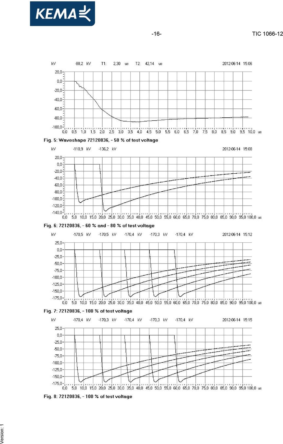
14 -14- TIC Impulse test followed by a voltage test Impulse test Standard IEC , clause Test date 14 June 2012 Environmental conditions Ambient temperature 20 C Temperature of test object 20 C Characteristic test data Specified test voltage 170 kv testing arrangement polarity voltage applied (% of test voltage) no. of impulses see figure voltage earthed applied to conductors metallic positive (2,30 / 42,1 µs) screens and 4 conductors metallic negative (2,30 / 42,1 µs) screens and 8 Note The three cable cores were tested simultaneously. Requirement Each core of the cable shall withstand without failure 10 positive and 10 negative voltage impulses.
 screens 65 1 6 80 1 6 100 10 7 and 8 Note The three cable cores were tested simultaneously.")
15 -15- TIC

16 -16- TIC
17 -17- TIC Voltage test Standard IEC , clause Test date 15 June 2012 Environmental conditions Ambient temperature 20 C Temperature of test object 20 C testing arrangement voltage applied, 50 Hz duration voltage applied to earth connected to xu 0 (kv) (min) conductors metallic screens 3, Note The three cable cores were tested simultaneously. Requirement No breakdown of the insulation shall occur.

18 -18- TIC Voltage test for 4 hours Standard IEC , clause Test date 14 June 2012 Environmental conditions Ambient temperature 20 C Temperature of test object 20 C testing arrangement voltage applied, 50 Hz voltage applied to earth connected to xu 0 (kv) (h) conductors metallic screens duration Note The three cable cores were tested simultaneously. Requirement No breakdown of the insulation shall occur.

19 -19- TIC Resistivity of semi-conducting screens Standard IEC , clause Test period 17 July 2012 Characteristic test data Temperature during ageing 100 ± 2 C Duration 7 days Resistivity measured at 90 C conductor screen - without ageing Ωm after ageing Ωm insulation screen - without ageing Ωm after ageing Ωm Note The measurement of resistivity shall be at a temperature within ± 2 C of the maximum conductor temperature in normal operation.

20 -20- TIC NON-ELECTRICAL TYPE TESTS 4.1 Measurement of thickness of insulation Standard IEC , clause 19.1 Test date 27 July 2012 insulation thickness unit requirement specified measured/determined - nominal mm - 8,0 - average mm - 8,02 - minimum (t min ) mm 7,10 7,35 - maximum (t max ) mm - 8,32 - (t max - t min ) / t max 0,15 0,12
 mm 7,10")
21 -21- TIC Measurement of thickness of non-metallic sheaths Standard IEC , clause 19.2 Test date 27 July 2012 Separation sheath thickness unit requirement calculated measured/determined - nominal mm 1,6 1,6 - average mm - - 2,90 - minimum (t min ) mm 1,08-2,67 Oversheath thickness unit requirement specified measured/determined - nominal mm 3,00 3,00 - average mm - - 3,18 - minimum (t min ) mm 2,45-2,86 Note The nominal thickness of the separation sheath is calculated according to clause and Annex A of IEC
22 -22- TIC Tests for determining the mechanical properties of the insulation before and after ageing Standard IEC , clause 19.3 Test period 15 and 16 August 2012 Characteristic test data Temperature during ageing 100 ± 2 C Duration 7 days without ageing - tensile strength N/mm² 12,5 31,4 - elongation % after ageing - tensile strength N/mm² - 28,2 - variation with samples without ageing % ± 25 max elongation % variation with samples without ageing % ± 25 max. 9
23 -23- TIC Tests for determining the mechanical properties of non-metallic sheaths before and after ageing Standard IEC , clause 19.4 Test period 15 to 17 August 2012 Characteristic test data Temperature during ageing 135 ± 3 C Duration 7 days Inner sheath/separation sheath without ageing - tensile strength N/mm² 12,5 28,2 - elongation % after ageing - tensile strength N/mm² 12,5 24,4 - variation with samples without ageing % ± 25 max elongation % variation with samples without ageing % ± 25 max. 8 Oversheath without ageing - tensile strength N/mm² 12,5 22,4 - elongation % after ageing - tensile strength N/mm² 12,5 20,5 - variation with samples without ageing % ± 25 max elongation % variation with samples without ageing % ± 25 max. -10
24 -24- TIC Additional ageing test on pieces of completed cable Standard IEC , clause 19.5 Test period 15 to 17 August 2012 Characteristic test data Temperature during ageing 100 ± 2 C Duration 7 days Insulation - tensile strength N/mm² - 32,0 - variation with samples without ageing % ± 25 max. 2 - elongation % variation with samples without ageing % ± 25 max. 19 Inner sheath/separation sheath - tensile strength N/mm² 12,5 29,9 - variation with samples without ageing % ± 25 max. 6 - elongation % variation with samples without ageing % ± 25 max. 3 Oversheath - tensile strength N/mm² 12,5 22,4 - variation with samples without ageing % ± 25 max. 0 - elongation % variation with samples without ageing % ± 25 max. -2
25 -25- TIC Loss of mass test on PVC sheaths of type ST 2 Standard IEC , clause 19.6 Test period 13 August 2012 Characteristic test data Temperature during ageing 100 ± 2 C Duration 7 days Inner sheath/separation sheath - loss of mass mg/cm 2 1,5 0,5 Oversheath - loss of mass mg/cm 2 1,5 0,5
26 -26- TIC Pressure test at high temperature on non-metallic sheaths Standard IEC , clause 19.7 Test date 16 and 17 August 2012 Characteristic test data (PVC insulation) Temperature 90 ± 2 C Duration 6 h Load 11 N Inner sheath/separation sheath - depth of indentation % max Characteristic test data (oversheath) Temperature 90 ± 2 C Duration 6 h Load 13 N Oversheath - depth of indentation % 50 21
27 -27- TIC Test on PVC insulation and sheaths at low temperatures Standard IEC , clause 19.8 Test date 27 July to 8 August 2012 Characteristic test data (separation sheath) Temperature -15 ± 2 C Cooling time 16 h Mass of hammer 1500 g Inner sheath/separation sheath - elongation % cold impact test - no cracks no cracks Characteristic test data (oversheath) Temperature -15 ± 2 C Cooling time 16 h Mass of hammer 1500 g Oversheath - elongation % cold impact test - no cracks no cracks
28 -28- TIC Test for resistance of PVC insulation and sheaths to cracking (heat shock test) Standard IEC , clause 19.9 Test date 16 August 2012 Characteristic test data (inner-/separation sheath) Temperature 150 ± 3 C Duration 1 h Diameter of mandrel 6 mm Number of turns Inner sheath/separation sheath - soundness - no cracks no cracks Characteristic test data (oversheath) Temperature 150 ± 3 C Duration 1 h Diameter of mandrel 6 mm Number of turns Oversheath - soundness - no cracks no cracks
29 -29- TIC Hot set test for XLPE insulation Standard IEC , clause Test date 14 August 2012 Characteristic test data Air temperature 200 ± 3 C Time under load 15 min Mechanical stress 20 N/cm 2 - elongation under load % permanent elongation % 15-3
30 -30- TIC Water absorption test on insulation Standard IEC , clause Test period 22 June to 12 July 2012 Characteristic test data Temperature 85 ± 2 C Duration 14 days - variation of mass mg/cm 2 1 0,06
31 -31- TIC Flame spread test on single cables Standard IEC , clause and IEC Test date 15 August 2012 Characteristic test data Duration 4 min - length free of charring mm > downward limit charred surface mm <
32 -32- TIC Shrinkage test for XLPE insulation Standard IEC , clause Test date 12 July 2012 Characteristic test data Temperature 130 ± 3 C Duration 1 h - shrinkage % 4 2
33 -33- TIC VERIFICATION OF CABLE CONSTRUCTION Verification of cable construction was carried out in accordance with clauses 5-14 of IEC The results are presented below. item unit requirement specified measured/ determined conductor - diameter of conductor mm 33, ,25 - number of wires diameter of wires mm - 4,05 - resistance at 20 C Ω/km 0,0283 0,0283 observed/determined construction - copper conductor Ø 30,25 mm; number wires conductor screen Ø 32,30 mm; thickness 0,62 mm - insulation Ø 48,70 mm; thickness 8,02 mm - insulation screen Ø 49,75 mm; thickness 0,56 mm - semi conductive tape - copper wire screen number wires 96; Ø 0,66 mm - copper tape - tape - inner sheath Ø 56,75 mm; thickness 2,90 mm - aluminium wire armour number wires 68; Ø 2,50 mm - tape - outer sheath Ø 67,5 mm; 3,18 mm outer diameter of the cable, average (mm) Ø 67,50 outer diameter of the core, average (mm) Ø 49,75 No significant deviations from the specified requirements were found.
34 -34- TIC APPENDIX A MEASUREMENT UNCERTAINTIES The measurement uncertainties in the results presented are as specified below unless otherwise indicated. measurement measurement uncertainty dielectric tests and impulse current tests: peak value 3% time parameters 10% capacitance measurement 0,3% tan δ measurement ± 0,5% ± 5 x 10⁻⁵ partial discharge measurement: < 10 pc 2 pc 10 to 100 pc 5 pc > 100 pc 20% measurement of impedance AC-resistance measurement 1% measurement of losses 1% measurement of insulation resistance 10% measurement of DC resistance: 1 to 5 µω 1% 5 to 10 µω 0,5% 10 to 200 µω 0,2% radio interference test 2 db calibration of current transformers 2,2 x 10⁻⁴ I i /I u and 290 µrad calibration of voltage transformers 1,6 x 10⁻⁴ U i /U u and 510 µrad measurement of conductivity 5% measurement of temperature: -50 to -40 C 3 K -40 to125 C 2 K 125 to 150 C 3 K tensile test 1% sound level measurement type 1 meter as per IEC and ANSI S1,4,1971 measurement of voltage ratio 0,1%
35 -35- TIC APPENDIX B MANUFACTURER S DRAWING(S)/DATA SHEET
R=Required by Lab S=May be subcontracted IEC SYSTEM FOR CONFORMITY TESTING AND CERTIFICATION OF ELECTRICAL EQUIPMENT COMMITTEE OF TESTING LABORATORIES
 IEC SYSTEM FO CONFOMITY TESTING AND CETIFICATION OF ELECTICAL EQUIPMENT COMMITTEE OF TESTING LABOATOIES TESTING AND MEASUING EQUIPMENT/ALLOWED SUBCONTACTING Power cables with extruded insulation and their
UGVCL/SP/591/11KV HT AB CABLE
 TECHNICAL SPECIFICATION FOR 11KV AERIAL BUNCHED CABLES FOR OVERHEAD LINES (CROSSED LINKED POLYTHENE DRY GAS CURED) 1. SCOPE This specification covers requirements of XLPE insulated, 11 KV Aerial Bunched
INTERNATIONAL STANDARD
 INTERNATIONAL STANDARD IEC 60502-1 Second edition 2004-04 Power cables with extruded insulation and their accessories for rated voltages from 1 kv (U m = 1,2 kv) up to 30 kv (U m = 36 kv) Part 1: Cables
TYPE TEST CERTIFICATE OF SHORT-CIRCUIT PERFORMANCE. A three-phase outdoor oil-immersed distribution transformer
 168-08 TYPE TEST CERTIFICATE OF SHORT-CIRCUIT PERFORMANCE APPARATUS A three-phase outdoor oil-immersed distribution transformer DESIGNATION 1000 kva SERIAL No. 1-08-112-01-0001 Rated power Rated voltage
T A B L E T 1 T E S T S A N D I N S P E C T I O N C A B L E P C U T A N D P C U T - A
 T A B L E T 1 1 of 7 Tests & Inspection Cable PCUT & PCUT-A (Table T1) T E S T S A N D I N S P E C T I O N C A B L E P C U T A N D P C U T - A No. Test Scale MOC Requirements G 20:10:001:01 Defined Test
EDS 02-0027 11KV TRIPLEX CABLE
 THIS IS AN UNCONTROLLED DOCUMENT, THE READER MUST CONFIRM ITS VALIDITY BEFORE USE Document Number: EDS 02-0027 ENGINEERING DESIGN STANDARD EDS 02-0027 11KV TRIPLEX CABLE Network(s): EPN, LPN, SPN Summary:
KNOW YOUR OPTIONS: 69 KV XLPE POWER CABLE
 Know Your Options: 69 kv XLPE Power Cable 3 material and size material is a matter of both customer preference and required current carrying capacity Copper conductor common for larger loads When both
CONFLEX ELECTRIC CABLE
 CONFLEX ELECTRIC CABLE CONFLEX - 0.6/1kV Flexible VSD/EMC Cables Applications WW VSD/EMC cables are manufactured for use where electrical interference distorts signal transmission in electric motors. Standard
SCHEDULE ' A' TECHNICAL SPECIFICATION FOR 11/22/33KV H.T.XLPE POWER CABLE FOR DISTRIBUTION NETWORK IN MAHARASHTRA (SPECIFICATION NO.
 SCHEDULE ' A' TECHNICAL SPECIFICATION FOR 11/22/33KV H.T.XLPE POWER CABLE FOR DISTRIBUTION NETWORK IN MAHARASHTRA (SPECIFICATION NO.MM/I/HTXLPE/2006) MAHARASHTRA STATE ELECTRICITY DISTRIBUTION CO.LTD.
High Voltage Systems. Today. The history of cables
 High Voltage Cables High Voltage Systems Today Prysmian Cables and Systems B.V. is part of the Prysmian Group, a leading player in the industry of high-technology cables and systems for energy and telecommunications,
Cables, Cable Laying & Accessories Manual
 Distribution Business Cables, Cable Laying & Accessories Manual Database ref: File Ref: Title Page & Revision Log For Cables & Access v4 - Nov 2003.doc Manual Name: Cables & Accessories Manual Version
KNOW YOUR OPTIONS: 230 KV POWER CABLES
 KNOW YOUR OPTIONS: 230 KV POWER CABLES 71 CONDUCTOR MATERIAL AND SIZE Conductor material is a matter of both customer preference and required current carrying capacity At 230 kv, copper is most common
COAX Cables Radio Frequency Cables
 COAX Cables Radio Frequency Cables Contents Page Table of contents Pictographs General information Introduction Types and abbreviations Temparature range Construction Characteristics Special constructions
6 ELECTRICAL PARAMETERS
 6 ELECTRICAL PARAMETERS For power, low voltage and medium voltage cables, cross section nominal areas are calculated in taking into account several parameters as: permissible current carrying capacities
Section 5 161 kv Power Cables
 Know Your Options: 161 kv Power Cable 61 material and size material is a matter of both customer preference and required current carrying capacity Copper conductor common for larger loads When both copper
FIRE RESISTANT CABLE CONSTRUCTION OF CABLES
 FIRE RESISTANT CABLE In all fire disasters, fire smoke, heat and toxic fumes are the main obstacles to safe evacuation of a building or area. A major contribution towards overcoming these hazards is the
ENERGY. TECWATER S1BN8-F 0,6/1 kv. Cable for Water Application
 ENERGY TECWATER S1BN8-F 0,6/1 kv Cable for Water Application Technical Data Electrical parameters Thermal parameters Trademark Type designation Specification Approval Application Rated voltage Maximum
IEEE POWER ENGINEERING SOCIETY CHICAGO CHAPTER THE OKONITE COMPANY WEDNESDAY JANUARY 11, 2006 JIM FITZGERALD ENGINEERING LINGO
 IEEE POWER ENGINEERING SOCIETY CHICAGO CHAPTER THE OKONITE COMPANY WEDNESDAY JANUARY 11, 2006 JIM FITZGERALD ENGINEERING LINGO WHEN YOU HEAR AN ENGINEER SAY A NUMBER OF DIFFERENT APPROACHES ARE BEING IMPLEMENTED
PROFIBUS cable. for PROFIBUS-PA and -DP 10/63-6.46 EN
 for PROFIBUS-PA and -DP 10/63-6.46 EN CPN 080/CPE 080-Ex PROFIBUS-PA basis cable AWG 18, 0.88 mm 2 Use For fixed installation indoor and outdoor, on racks and in conduits. Application Fieldbus cable for
Communication, Signal & Data Cables
 Communication, Signal & Data Cables Used for indoor installation and interconnection of transmission, telephone, telegraph and electronic equipment as well as media equipments www.alfanar.com Communication
XLPE Land Cable Systems User s Guide. Rev 5
 XLPE Land Cable Systems User s Guide Rev 5 CONTENT XLPE Land Cable Systems Introduction... 3 Design, installation and testing... 4 XLPE cables... 4 Cable accessories... 4 Installation of XLPE cable systems...
TECHNICAL SPECIFICATION OF 11 / 22 KV XLPE POWER CABLE FOR SUB-STATION
 GUJARAT ENERGY TRANSMISSION CORPORATION LTD. Sardar Patel Vidyut Bhavan, Race Course, Vadodara 390 007 TECHNICAL SPECIFICATION OF 11 / 22 KV XLPE POWER CABLE FOR SUB-STATION GETCO/E/TS PCBL025/RO DT.07-03-2008
HINDUSTAN PETROLEUM CORPORATION LIMITED ENGINEERING & PROJECTS GRESHAM ASSURANCE HOUSE, 2 ND FLOOR, A-1595(3) 1-A, SIR P M ROAD, FORT MUMBAI-400 001
 1-A, SIR P M ROAD, FORT MUMBAI-400 001") NEW POL DEPOT AT HINDUSTAN PETROLEUM CORPORATION LIMITED ENGINEERING & S GRESHAM ASSURANCE HOUSE, 2 ND FLOOR, A-1595(3) 1-A, SIR P M ROAD, FORT MUMBAI-400 001 TECHNICAL SPECIFICATION OF XLPE, FRLS LT CABLES
NEW POL DEPOT AT HINDUSTAN PETROLEUM CORPORATION LIMITED ENGINEERING & S GRESHAM ASSURANCE HOUSE, 2 ND FLOOR, A-1595(3) 1-A, SIR P M ROAD, FORT MUMBAI-400 001 TECHNICAL SPECIFICATION OF XLPE, FRLS LT CABLES
3.6/6 kv XLPE insulated cables 5. 6/10 kv XLPE insulated cables 15. 8.7/15 kv XLPE insulated cables 25. 12/20 kv XLPE insulated cables 35
 CONTENTS INTRODUCTION 1 Cable selection, cable specification, cable services CABLES Constructional data: 3.6/6 kv XLPE insulated cables 5 SECTION 1 6/10 kv XLPE insulated cables 15 SECTION 2 8.7/15 kv
Network Standard Advice No. 1420C 9/6/2011
 Network Standard Advice No. 1420C 9/6/2011 TO: Customers, Service Providers and Ausgrid Staff. Advisory Note on Changes to the Use of 11kV Cable Types. Introduction This Network Standard Advice (NSA) provides
High-ohmic/high-voltage resistors
 FEATURES High pulse loading capability Small size. APPLICATIONS Where high resistance, high stability and high reliability at high voltage are required High humidity environment White goods Power supplies.
MEDIUM VOLTAGE POWER CABLES
 MEDIUM VOLTAGE POWER CABLES CONTENTS 1 GENERAL INTRODUCTION 4 TECHNICAL INFORMATION 15 25 35 45 Single Core XLPE Insulated PVC Sheathed Cables UNARMOURED CABLES COPPER UNARMOURED CABLES ALUMINUM ALUMINUM
CAVEL VS80205 MADE IN ITALY 1000 V
 0,05 9,00 x 7,20 (Pet) (LSZH) Attached CE01 CE02 Sheath Colour black black red Non-migrating Polyester tape longitudinally overlapped (Pet) 25 x 23 µm Outer sheath of Thermoplastic material - black - halogen-free,
Fault location on power cables. Fault location on power cables
 Fault location on power cables Fault location on power cables Contents: 1. Introduction 2. Construction of power cables 3. Cable faults 01. Introduction Fault location on communication and power cables
International Electrotechnical Commission Standards
 International Electrotechnical Commission Standards Standard IEC 60028 IEC 60038 IEC 60050-461 IEC 60055-1 IEC 60055-2 IEC 60092-101 IEC 60092-350 IEC 60092-351 IEC 60092-352 IEC 60092-353 IEC 60092-354
MV CABLE TYPE C 33-226
 MV CABLE TYPE C 33-226 Standards : CENELEC HD 620 C 33-226 Rated voltage Rated voltage : 12/20 (24) kv Design 1 Stranded aluminium, class 2 conductor 2 Extruded conducting screen on conductor 3 XLPE insulation
HIGH VOLTAGE XLPE CABLE SYSTEMS. Technical User Guide
 HIGH VOLTAGE XLPE CABLE SYSTEMS Technical User Guide Content 1. General information on High Voltage XLPE Cable Systems 1.1. Introduction 1.2. Cable selection process 1.3. Service life 3 3 3 4 2. Cable
THE PATHWAY TO POWER HIGH-VOLTAGE CABLES
 THE PATHWAY TO POWER HIGH-VOLTAGE CABLES TABLE OF CONTENTS HIGH-VOLTAGE CABLES 3 Advantages of XLPE-insulated cable systems 3 PROPOSAL 4 Cable systems 4 Providing System Solutions 4 Continuous temperature
High-ohmic/high-voltage resistors
 FEATURES These resistors meet the safety requirements of: UL1676 (range 510 kω to 11 MΩ) EN60065 BS60065 (U.K.) NFC 92-130 (France) VDE 0860 (Germany) High pulse loading capability Small size. APPLICATIONS
LOW VOLTAGE RING TYPE MEASURING CURRENT TRANSFORMERS
 Specification for LOW VOLTAGE RING TYPE MEASURING CURRENT TRANSFORMERS CEYLON ELECTRICITY BOARD SRI LANKA Specification for LOW VOLTAGE RING TYPE MEASURING CURRENT TRANSFORMERS CEB Standard 027: 1998 CEYLON
3.1.1 Full Type Tests & Routine Tests according to Clause 8 2 & 8 3. 4.0 Instructions For Installation, Operation & Maintenance
 SPECIFICATION FOR LOW VOLTAGE SWITCHBOARD SEN I N D E X Description 10 STANDARD TECHNICAL REQUIREMENTS 11 Standards 12 General Operating Conditions 13 General Description Of Switchboard 131 Structure 132
A Study of a MV Cable Joint
 SERBIAN JOURNAL OF ELECTRICAL ENGINEERING Vol. 7, No. 1, May 2010, 1-11 UDK: 621.315.35:537.212 A Study of a MV Cable Joint Radiša Dimitrijević 1, Neda Pekarić-Nađ 2, Miodrag Milutinov 3 Abstract: Construction
TECHNICAL SPECIFICATION FOR LOW-FREQUENCY CABLES AND WIRES WITH PVC INSULATION AND PVC SHEATH
 Rev. 1:2007 TECHNICAL SPECIFICATION FOR LOW-FREQUENCY CABLES AND WIRES WITH PVC INSULATION AND PVC SHEATH Suruhanjaya Komunikasi dan Multimedia Malaysia Off Pesiaran Multimedia, 63000 Cyberjaya, Selangor
Gulf Cable & Electrical Ind. Co.
 CONTENTS INTRODUCTION PRODUCT RANGE I PRODUCT DATA TABLES XLPE INSULATED 600/1000V CABLES Two Core Cables CU/XLPE/PVC/LC/PVC/SWA/PVC 1 Three Core Cables CU/XLPE/PVC/LC/PVC/SWA/PVC 2 Four Core Cables CU/XLPE/PVC/LC/PVC/SWA/PVC
VIPERFLEX ELECTRIC CABLE
 VIPERFLEX Flexible Low Voltage Electric Cable - 0.6/1kV (Rubber insulated) H07 RN-F & H07 BN-F Single Core 2-Core 2-Core and Earth 3-Core and Earth 4-Core and Earth Multi-Core and Earth H07 RCN-F & H07
EVALUATION OF ON-SITE DIELECTRIC RESPONSE METHODS FOR NON- DESTRUCTIVE TESTING OF WATER TREED MV XLPE CABLES
 EVALUATION OF ON-SITE DIELECTRIC RESPONSE METHODS FOR NON- DESTRUCTIVE TESTING OF WATER TREED MV XLPE CABLES Sverre Hvidsten*, Peter Werelius**, Jørgen Christensen*** * SINTEF Energy Research (SEfAS),
TECHNICAL SPECIFICATION
 TECHNICAL SPECIFICATION 4 PAIR UTP CABLE (ENHANCED CATEGORY 5) PVC (CM Grade) Page 1 of 6 1. SCOPE This specification is based on the specifications of UL 444, ANSI/TIA/EIA-568-B.2, UL 1685 and covers
INTERNATIONAL STANDARD
 INTERNATIONAL STANDARD IEC 61156-5 First edition 2002-03 Multicore and symmetrical pair/quad cables for digital communications Part 5: Symmetrical pair/quad cables with transmission characteristics up
Removal of EP 20 10 00 02 SP High Voltage Cable
 TN 018: 2014 Technical Note For queries regarding this document standards@asa.transport.nsw.gov.au www.asa.transport.nsw.gov.au TN 018: 2014 Issued date 12 March 2014 Effective dates 12 March 2014 Subject:
DOMESTIC ELECTRICAL INSTALLATION CERTIFICATE (Requirements for Electrical Installations BS 7671 IEE Wiring Regulations)
") DOMESTIC ELECTRICAL INSTALLATION CERTIFICATE (Requirements for Electrical Installations BS 7671 IEE Wiring Regulations) DETAILS OF THE CLEINT Client and address ADDRESS OF THE INSTALLATION Installation
DOMESTIC ELECTRICAL INSTALLATION CERTIFICATE (Requirements for Electrical Installations BS 7671 IEE Wiring Regulations) DETAILS OF THE CLEINT Client and address ADDRESS OF THE INSTALLATION Installation
ALARMLINE ANALOGUE Linear Heat Detection System
 ALARMLINE ANALOGUE Alarmline Analogue sensor cable senses temperature variations by continuously monitoring the resistance of specially doped N.T.C. polymeric insulation. A change in temperature produces
CHAPTER VIII LINE PLANT SYSTEM COMMUNICATION THROUGH RE CABLE
 CHAPTER VIII LINE PLANT SYSTEM COMMUNICATION THROUGH RE CABLE 8.1 SYSTEM 8.1.1 Armoured, screened underground cables are used for control communication in electrified areas to limit induction effect. 8.2
Flexible cables for submersible products
 Flexible cables for submersible products Standards SUBCAB cables complies with the following general standards: IEC 6045 (general) IEC 608 class 5 (conductor) IEC 608-- CLAUSE 9 (oil resistant) IEC 608--
Cable Guide. Cables, Connectors & Tools for installation of quality networks. TRIAX - your ultimate connection
 Cable Guide Cables, Connectors & Tools for installation of quality networks TRIAX - your ultimate connection A Selection of the best Triax TX Cable range optimised for digital reception Simplification
MiCAFIL. 1 RIP Technology. Bushings. Z. Zic 09/2003
 MiCAFIL 1 RIP Technology Z. Zic 09/2003 )XQFWLRQRI+LJK9ROWDJH%XVKLQJ Uncontrolled (natural) electrical field Capacity-controlled electrical field %XVKLQJV0DLQ,QVXODWLRQ6\VWHPV 7\SH 0DLQ,QVXODWLRQ +RXVLQJFRYHU
ScottishPower Distribution Cables & Equipment. Metal Theft
 ScottishPower Distribution Cables & Equipment Metal Theft April 2012 As an aid to deterring to metal theft this booklet has been put together to help identify the types of utility power cables and associated
KALPANA INDUSTRIES LTD. TECHNICAL DATA SHEET
 1 KALPANA INDUSTRIES LTD. TECHNICAL DATA SHEET KI XL - 03 / KI-SC 10 TWO COMPONENT AMBIENT CURABLE POLYETHYLENE COMPOUND FOR INSULATION OF LOW VOLTAGE POWER CABLE DESCRIPTION : KI polyethylene compound
CABLE ACCESSORIES 110-220 kv
 CABLE ACCESSORIES 110-220 kv Termination 110 kv Technical description Termination MKB 126 / 145 with composite type insulator uses for cable line joints with other elements of power-supply systems. Termination
SCHEDULE ' A ' TECHNICAL SPECIFICATION FOR SINGLE CORE,UNARMOURED L.T.XLPE POWER CABLE FOR DISTRIBUTION NETWORK IN MAHARASHTRA
 SCHEDULE ' A ' TECHNICAL SPECIFICATION FOR SINGLE CORE,UNARMOURED L.T.XLPE POWER CABLE FOR DISTRIBUTION NETWORK IN MAHARASHTRA (SPECIFICATION NO.MM/I/ 1 X C-UA- LTXLPE/2006) MAHARASHTRA STATE ELECTRICITY
PROFIBUS cable. PROFIBUS DP cables Non-Ex (Hazardous) applications Ex (Hazardous) applications
 applications Ex (Hazardous) applications") Data Sheet 10/63-6.47-EN Rev. D PROFIBUS cable PROFIBUS DP cables Non-Ex (Hazardous) applications Ex (Hazardous) applications PROFIBUS PA cables Non-Ex (Hazardous) applications Ex (Hazardous) applications
Data Sheet 10/63-6.47-EN Rev. D PROFIBUS cable PROFIBUS DP cables Non-Ex (Hazardous) applications Ex (Hazardous) applications PROFIBUS PA cables Non-Ex (Hazardous) applications Ex (Hazardous) applications
The table below lists the symbols used on the Clamp and/or in this manual. Important Information. See manual.
 i800 AC Current Clamp Instruction Sheet Introduction The i800 AC Current Clamp, the Clamp, has been designed for use with multimeters, recorders, power analyzers, safety testers, etc., for accurate non-intrusive
ELECTRICAL INSULATION TESTING OF HV EQUIPMENT UP TO 33kV
 1. SCOPE This document details PowerSystems requirements for electrical testing of HV Equipment up to and including 33kV. 2. ISSUE RECORD This is a Reference document. The current version of Controlled
MEDIUM VOLTAGE CABLES Up to and including 36 KV
 MEDIUM VOLTAGE CABLES Up to and including 6 KV NOTICE As this catalogue is not intendedto cover all of LIBAN CABLES SAL possibilities in special cables manufacturing, the hereafter listing of the types
SURGE PROTECTIVE DEVICES
 SURGE PROTECTIVE DEVICES 1. INTRODUCTION In order to ensure safety of people, protection of equipment and, to a certain extent, continuity of supply, insulation co-ordination aims at reducing the likelihood
Cable Selection for Medium Voltage Capacitor Banks and Harmonic Filter Banks
 Cable Selection for Medium Voltage Capacitor Banks and Harmonic Filter Banks Introduction This document presents the fundamental aspects of cable and conductor selection for connecting pad mounted shunt
4 IX D N E P P A Installation methods Current-carrying capacity and voltage drop for cables Reference method IET Wiring Matters
 8 Appendix 4 of BS 7671 by Mark Coles Appendix 4, Current-carrying capacity and voltage drop for cables and flexible cords, has seen significant changes with the publishing of BS 7671:2008. This article
Automotive Electronics Council Component Technical Committee
 AEC - Q101-005 - REV- ATTACHMENT 5 AEC - Q101-005 Rev- CAPACITIVE DISCHARGE MODEL (CDM) ELECTROSTATIC DISCHARGE (ESD) TEST METHOD - 005 DISCRETE COMPONENT CHARGED DEVICE MODEL (CDM) ELECTROSTATIC DISCHARGE
AC and Pulse Film Foil Capacitors KP Radial Potted Type
 AC and Pulse Film Foil Capacitors KP Radial Potted Type 0.5 L max. W max. Marking H max. FEATURES 5 mm lead pitch, supplied loose in box taped in ammopack or reel Material categorization: for definitions
APPLICATION ORIENTED DESIGN OF CABLES
 APPLICATION ORIENTED DESIGN OF CABLES Mrs. Rohini Bhattacharyya, Dubai cables Ltd.P. O. Box 11529,Dubai. rohinib@ducab.com Mr. Nawaf Ahmad Al Mohaideb Dubai Cables Ltd. P. O. Box 11529, Dubai. Nawaf@ducab.com
Transformer Bushings for GIS
 Transformer Bushings for GIS Oil to SF6 Connections GARIP RTKG 725-55 kv SQS certified ISO 91 / ISO 141 Bushings RIP - Technology for SF6 / Oil - Bushings In modern metal enclosed switchgear SF6 -gas is
Flygt flexible cables
 Flygt flexible cables Contents Standards General SUBCAB 4 Screened SUBCAB 6 Rubber cable type: NSSHÖU-J 7 Screened rubber cable type: NSSHÖU../E + ST 8 FGB screened rubber cable 9 PUR control cable 0 HCR
Guide to the electrical parameter classifications of IEC 60950 and IEC 62368 safety standards
 Guide to the electrical parameter classifications of IEC 60950 and IEC 62368 safety standards Abstract This Guide is an informative listing of selected terms and definitions found in IEC Glossary entry
VDE Information. Degree of Pollution, Clearances and Creepage Distances and Insulating Materials
 VDE Information General Information The voltage which can be applied to a terminal depends on the relevant regulations, the installation conditions and, of course, the dimensions and insulating materials
Gulf Cable & Electrical Ind. Co.
 CONTENTS INTRODUCTION PRODUCT RANGE I PRODUCT DATA TABLES Irrigation 1 Coaxial s for T.V/ Satellite Antenna etc 2 Data Transmission s - 4 pair 24 AWG 3 TELEPHONE CABLES Telephone cables CCP-LAP & CCP-LAP-SS
100% EMI Emission Containment
 100% EMI Emission Containment Designed for Longer Service Life Highly Flexible for Easier Handling and Faster Installation Authorized Distributor Industrial VFD Cables Index n Variable Frequency Drive
Tri-Rated Flexible PVC Equipment Wire
 Application: High temperature, flame retardant wire designed for use in the switch control, relay and instrumentation panels of power switchgear and for purposes such as internal connectors in rectifier
Uniprise Solutions COAX 101. White Paper. www.commscope.com
 Uniprise Solutions COAX 101 White Paper www.commscope.com Structured cable systems have very thorough standards for fiber optic and twisted pair installations. The cabling components and installed systems
PTC-Resistor Temperature-Sensors MINIKA to DIN 44 081 and DIN 44 082
 PTC-Resistor Temperature-Sensors MINIKA to DIN 44 081 and DIN 44 082 General PTC-resistor temperature sensors (also called PTC-resistors or thermistors) are temperatur dependent semiconductor resistors
DELHI METRO RAIL CORPORATION LIMITED. (A Joint Venture of Govt. of India & GNCTD) MASS RAPID TRANSPORT SYSTEM PHASE III. Contract: - CE -16 VOLUME-6
 MASS RAPID TRANSPORT SYSTEM PHASE III. Contract: - CE -16 VOLUME-6") DELHI METRO RAIL CORPORATION LIMITED (A Joint Venture of Govt. of India & GNCTD) MASS RAPID TRANSPORT SYSTEM PHASE III TURNKEY PROJECT OF DESIGN, SUPPLY, LAYING, JOINTING, TESTING AND COMMISSIONING OF
DELHI METRO RAIL CORPORATION LIMITED (A Joint Venture of Govt. of India & GNCTD) MASS RAPID TRANSPORT SYSTEM PHASE III TURNKEY PROJECT OF DESIGN, SUPPLY, LAYING, JOINTING, TESTING AND COMMISSIONING OF
Unified requirements for systems with voltages above 1 kv up to 15 kv
 (1991) (Rev.1 May 2001) (Rev.2 July 2003) (Rev.3 Feb 2015) Unified requirements for systems with voltages above 1 kv up to 15 kv 1. General 1.1 Field of application The following requirements apply to
Power and Wiring Cables
 1 Single-Core PVC 1X...................... 1: Single-Core PVC/PVC 1Y.................. 1: Flat Twin & Flat Three Core PVC /Y........ 1: Multicore XLPE/LSF/SWA/LSF BS Control Cable.............................
VDE-approved PVC-Control Cables
 Works photo: HELUKAEL VDE-approved PVC-Control Cables VDE-approved PVC-Control Cables This certification/licency is issued according to the rules of the HAR Agreement, wherein the certification/ licency
Metal-Oxide Varistors (MOVs) Surface Mount Multilayer Varistors (MLVs) > MLN Series. MLN SurgeArray TM Suppressor. Description
 Surface Mount Multilayer Varistors (MLVs) > MLN Series. MLN SurgeArray TM Suppressor. Description") MLN SurgeArray TM Suppressor RoHS Description The MLN SurgeArray Suppressor is designed to help protect components from transient voltages that exist at the circuit board level. This device provides four
MLN SurgeArray TM Suppressor RoHS Description The MLN SurgeArray Suppressor is designed to help protect components from transient voltages that exist at the circuit board level. This device provides four
SUITABILITY OF DIFFERENT TEST VOLTAGES FOR ON-SITE TESTING OF XLPE CABLE SYSTEMS
 SUITABILITY OF DIFFERENT TEST VOLTAGES FOR ON-SITE TESTING OF XLPE CABLE SYSTEMS Michael Hensel HIGHVOLT Prüftechnik Dresden GmbH 2 3 Content 1 Introduction Test parameters and their significance Differences
Commercial Coaxial Cable
 Commercial Coaxial Cable For the Best in COMMERCIAL TV Reception Solutions! Do you require a Digital TV reception system for your next project? Matchmaster can supply For The Best Design and supply of
DC Film Capacitors MKT Radial Potted Type
 DC Film Capacitors MKT Radial Potted Type FEATURES 15 mm to 27.5 mm lead pitch. Supplied loose in box and taped on reel Material categorization: for definitions of compliance please see www.vishay.com/doc?99912
TECHNICAL SPECIFICATION FOR HIGH TENSION LINE HARDWARE AND ACCESSORIES FOR ACSR PANTHER & WOLF CONDUCTOR
 TECHNICAL SPECIFICATION FOR HIGH TENSION LINE HARDWARE AND ACCESSORIES FOR ACSR PANTHER & WOLF CONDUCTOR 1.1.0 SCOPE : This specification covers design, manufacture, testing at manufacture s works before
Testing of Power Transformers. Routine tests, Type tests and Special tests
 Testing of Power Transformers Routine tests, Type tests and Special tests Testing of Power Transformers Routine tests, Type tests and Special tests Testing of Power Transformers Routine tests, Type tests
High Ohmic/High Voltage Metal Glaze Leaded Resistors
 High Ohmic/High Voltage FEATURES A metal glazed film is deposited on a high grade ceramic body. After a helical groove has been cut in the resistive layer, tinned electrolytic copper wires are welded to
Interference Suppression Film Capacitors MKP Radial Potted Type
 Interference Suppression Film Capacitors MKP Radial Potted Type FEATURES 7.5 mm to 27.5 mm lead pitch Supplied loose in box, taped on reel Material categorization: For definitions of compliance please
DS 600. A contact free flux gate based current measurement sensor 600A rms
 DS 600 A contact free flux gate based current measurement sensor 600A rms DS 600 is member of the small housing sensor family. The family includes a 200A and a 600A version. 600A rms - 900A peak Maximum
This is an unapproved Kinectrics International Draft Report, subject to change D R A F T DRAFT
 This is an unapproved Kinectrics International Draft Report, subject to change To: HES Hacilar Electrik San. Ve Tic. Erciyes Mah. HES Cad. No: 22 38210 Hacilar, Kayseri Turkey 1.0 INTRODUCTION D R A F
FAQs-Main switchboard design criteria
 FAQs-Main switchboard design criteria Q: What is the Australian standard for main switchboards? Current Australian standard is AS/NZS 3439.1: 2002 originating from IEC 60439. The new series of standard
BRÖCKSKES D-VIERSEN PV1-F 4,0 mm BRÖCKSKES D-VIERSEN PV1-F 4,0 mm d d 2 2 C VDE-REG.-Nr. 8292 10/2009
 d BRÖCKSKES BRÖCKSKES D-VIERSEN D-VIERSEN PV1-F PV1-F 4,0 mm 4,0 2 mm VDE-REG.-Nr. 2 C 8292 10/2009 s - THE COMPANY DIN EN ISO 9001 More than 60 years of experience in temperature measurement and control
Current Probes. User Manual
 Current Probes User Manual ETS-Lindgren L.P. reserves the right to make changes to any product described herein in order to improve function, design, or for any other reason. Nothing contained herein shall
Aluminum Electrolytic Capacitors Axial Miniature, Long-Life
 Aluminum Electrolytic Capacitors Axial Miniature, Long-Life 38 AML 0 ASM smaller dimensions Fig. QUICK REFERENCE DATA DESCRIPTION Nominal case sizes (Ø D x L in mm) 6.3 x.7 to 0 x 5 VALUE 0 x 30 to x 38
AC Line Rated Ceramic Disc Capacitors Class X1, 760 V AC, Class Y1, 500 V AC
 AC Line Rated Ceramic Disc Capacitors Class X1, 760 V AC, Class Y1, 500 V AC QUICK REFERENCE DATA DESCRIPTION VALUE Ceramic Class 1 2 Ceramic Dielectric U2J U2J Y5S, Y5U Y5S, Y5U Voltage (V AC ) 500 760
MOBILE SYSTEM FOR DIAGNOSIS OF HIGH VOLTAGE CABLES (132KV/220KV) VLF-200 HVCD
 VLF-200 HVCD") MOBILE SYSTEM FOR DIAGNOSIS OF HIGH VOLTAGE CABLES (132KV/220KV) VLF-200 HVCD VERY LOW FREQUENCY (VLF) - PARTIAL DISCHARGES AND TANGENT DELTA HV/EHV POWER CABLES DIAGNOSTIC AND ON-SITE FIELD TESTING WITH
MOBILE SYSTEM FOR DIAGNOSIS OF HIGH VOLTAGE CABLES (132KV/220KV) VLF-200 HVCD VERY LOW FREQUENCY (VLF) - PARTIAL DISCHARGES AND TANGENT DELTA HV/EHV POWER CABLES DIAGNOSTIC AND ON-SITE FIELD TESTING WITH
4 SENSORS. Example. A force of 1 N is exerted on a PZT5A disc of diameter 10 mm and thickness 1 mm. The resulting mechanical stress is:
 4 SENSORS The modern technical world demands the availability of sensors to measure and convert a variety of physical quantities into electrical signals. These signals can then be fed into data processing
Current Ratings. TABLE BEC 107. (Continued) Current ratings for 6350/11000 volts grade PILC/SWA/PVC cable to BS6480/69
 Current ratings for 6350/11000 volts grade PILC/SWA/PVC cable to BS6480/69") Ratings TBLE BEC 107. (Continued) ratings for 60/11000 volts grade PILC/SW/PVC cable to BS64/69 CBLES LID IN IR: The ratings given in the foregoing tables are based on an ambient of C. It is recommended
Ratings TBLE BEC 107. (Continued) ratings for 60/11000 volts grade PILC/SW/PVC cable to BS64/69 CBLES LID IN IR: The ratings given in the foregoing tables are based on an ambient of C. It is recommended
Guidance for upgrading to GB4943.1-2011 (IEC 60950-1: 2005, MOD)
") Guidance for upgrading to GB4943.1-2011 (IEC 60950-1: 2005, MOD) Note: This guidance document is a translation of official Chinese document which is issued by CQC (China Quality Certification Center) on
Guidance for upgrading to GB4943.1-2011 (IEC 60950-1: 2005, MOD) Note: This guidance document is a translation of official Chinese document which is issued by CQC (China Quality Certification Center) on
Development of 22-kV XLPE Cable and Joint with Reduced Insulation Thickness Having Water-Impervious Aluminum Layer
 Development of 22-kV XLPE Cable and Joint with Reduced Insulation Thickness Having Water-Impervious Aluminum Layer by Hiroyuki Mabuchi *, Satoru Koizumi *, Haruki Nozawa *, Yoshihiro Maeda * 2, Hideo Kawahara
Rated Lumen [lm] Nominal. Volts [V] [lm]
![Rated Lumen [lm] Nominal. Volts [V] [lm]](/thumbs/40/21093811.jpg "Rated Lumen [lm] Nominal. Volts [V] [lm]") GE Lighting rcstream Metal Halide lamps Tubular Clear 25W and W Elliptical Diffuse 25W DT SHEET Product information High brightness, high quality white light with good colour rendition and energy efficiency
GE Lighting rcstream Metal Halide lamps Tubular Clear 25W and W Elliptical Diffuse 25W DT SHEET Product information High brightness, high quality white light with good colour rendition and energy efficiency
WW12X, WW08X, WW06X, WW04X ±1%, ±5% Thick Film Low ohm chip resistors
 WW12X, WW08X, WW06X, WW04X ±1%, ±5% Thick Film Low ohm chip resistors Size 1206, 0805, 0603, 0402 *Contents in this sheet are subject to change without prior notice. Page 1 of 8 ASC_WWxxX_V12 Nov.- 2011
Cable Solutions for Servo and Variable Frequency Drives (VFD)
") Cable Solutions for Servo and Variable Frequency Drives (VFD) Electric drive systems with continuous torque and speed control are widespread today. They allow an optimal adjustment of the drive with respect
Cable Solutions for Servo and Variable Frequency Drives (VFD) Electric drive systems with continuous torque and speed control are widespread today. They allow an optimal adjustment of the drive with respect