THE MCINTOSH MC 2105 SOLID STATE STEREO POWER AMPLIFIER. Reading Time: 28 Minutes. Price $1.25
|
|
|
- Mavis Holland
- 7 years ago
- Views:
Transcription
1 THE MCINTOSH MC 2105 SOLID STATE STEREO POWER AMPLIFIER Reading Time: 28 Minutes Price $1.25

2

3 Your MC 2105 Stereo Power Amplifier will give you many years of pleasant and satisfactory performance. If you have any questions, please contact: CUSTOMER SERVICE Mclntosh Laboratory Inc. 2 Chambers Street Binghamton, New York Phone: WARNING: TO PREVENT FIRE OR SHOCK HAZARD, DO NOT EXPOSE THIS UNIT TO RAIN OR MOISTURE. Take Advantage of 3 years of FREE Factory Service... Fill in the Application NOW. CONTENTS SERVICE CONTRACT 1 INSTALLATION 2,3 HOW TO CONNECT 4,5 HOW TO USE THE DYNAMIC PEAK LOCKING METERS... 6 FRONT PANEL INFORMATION... 8 PERFORMANCE LIMITS AND RATINGS 9 TYPICAL PERFORMANCE CHARTS.. 10 TECHNICAL DESCRIPTION 11 BLOCK DIAGRAM 12 THREE YEAR FACTORY SERVICE CONTRACT An application for a FREE THREE YEAR FACTORY SERVICE CONTRACT is included with this manual. The terms of the contract are: 1. Mclntosh will provide all parts, materials and labor needed to return the measured performance of the instrument to the original performance limits free of any charge. The SERVICE CONTRACT does not cover any shipping costs to and from the authorized service agency or the factory. 2. Any Mclntosh authorized service agency will repair all Mclntosh instruments at normal service rates. To receive the free service under the terms of the SERVICE CONTRACT, the SERVICE CONTRACT CERTIFICATE must accompany the instrument when taken to the service agency. 3. Always have service done by a Mclntosh authorized service agency. If the instrument is modified or damaged, as a result of unauthorized repair the SERVICE CONTRACT will be cancelled. Damage by improper use or mishandling is not covered by the SERV- ICE CONTRACT. 4. The SERVICE CONTRACT is issued to you as the original purchaser. To protect you from misrepresentation this contract cannot be transferred to a second owner. 5. For your protection Mclntosh selects its dealers carefully. Only one dealer in ten qualifies for a Mclntosh franchise. To receive the SERVICE CONTRACT your purchase must be made from a Mclntosh franchised dealer. 6. Your completely filled in application for a SERVICE CONTRACT must be postmarked within 30 days of the date of purchase of the instrument. 7. To receive the SERVICE CONTRACT all information on the application must be filled in. The SERVICE CONTRACT will be issued when the completely filled in application is received at Mclntosh Laboratory Incorporated in Binghamton, New York. Copyright 1970 By Mclntosh Laboratory Inc. 1

4 Adequate ventilation extends the trouble-free life of electronic instruments. It is generally found that each 10 centigrade (18 F) rise in temperature reduces the life of electrical insulation by one half. Adequate ventilation is an inexpensive and effective means of preventing insulation breakdown that results from unnecessarily high operating temperatures. The direct benefit of adequate ventilation is longer, trouble-free life. Allow at least 15 inches deep x 17 inches wide x 8 inches high for mounting the MC2105. Always allow for air flow by either ventilation holes or space next to the bottom of the amplifier and a means for a warm air to escape at the top. With adequate ventilation the amplifier can be mounted in any position. To prepare the MC 2105 for installation remove the plastic protective covering. Turn it upside down so that it rests on its top on the shipping pallet. Remove the four plastic feet fastened to the bottom of the chassis. Next, place the mounting brackets, the parts bag and the mounting template at hand. The PANLOC professional mounting design eliminates the need for any shelf or bracket to support the MC It is completely supported by its own mounting brackets. The design of the mounting template allows you to position or locate the cutout from the front or rear of the panel to which the instrument is to be mounted. Position the plastic mounting template over the area of the panel to be cut out for installation. If the cutout is to be located from the front of the panel, begin at 2. If the cutout is to be located from the rear of the panel, begin here. 1. On the back of the cabinet panel, scribe a vertical centerline through the exact center of the area in which the cutout is to be made. Place the template against the back of the panel and match the template centerline with the centerline on the cabinet panel. Make sure that there is at least ¼ inch clearance between the bottom of the dashed line of the cutout area on the template and any shelf or brace below the proposed cutout. Mark the two locating holes ("C" holes on the mounting template). Drill the two locating holes. Be certain the drill is perpendicular to the panel. Now position the template on the front of the panel by aligning the "C" locating holes on the template with the drill holes. 2. If the cutout is to be located from the front of the panel: With the template in place against the cabinet panel, mark the "A" and "B" drill holes and the four small holes that identify the corners of the cutout. Join the corner marks with a pencil. The edge of the template can be used as a straight edge. IMPORTANT: DRILL THE 6 HOLES BEFORE MAKING THE CUTOUT. Accurately drill the three holes on each side of the cutout area with a 3 /16 inch drill. With the saw on the INSIDE OF THE PENCIL LINES carefully cut out the rectangular opening. Secure the mounting strips to the rear of the cabinet panel using two screws from the hardware package. Insert the screws in the center holes of the cabinet panel ("B" holes on the template) and tighten. The screw head should pull into the wood slightly. (Use two % inch long screws for panels under ½ inch, or two 1¼ inch long screws for panels ½ inch thick and larger.) 2

5 Attach the mounting brackets to the cabinet panel using four screws. Place the template over the mounting screws. The mounting screws should be centered in the "A" and "B" holes on the template. The sides of the mounting brackets should match the vertical dash lines on the template. If necessary, loosen the screws and push the brackets into alignment and retighten. Insert the power cord through the opening. Carefully slide the MC 2105 into the opening so the rails on the bottom of the equipment slide in the track of the mounting brackets. Slide the instrument in until it stops at the adjust position latches. Press the latches in and continue to slide the instrument in until the front panel is against the cabinet panel. At the bottom front corners of the PANLOC instruments are the PANLOC buttons. Depressing the PANLOC buttons will lock the instrument firmly in the installation. Depressing the PANLOC buttons a second time (as with a ballpoint pen) will release the instrument. You can then slide the instrument forward to the inspection-adjustment position. Depressing the inspection-adjustment position latches will allow the instrument to be slid completely out of the installation. 3

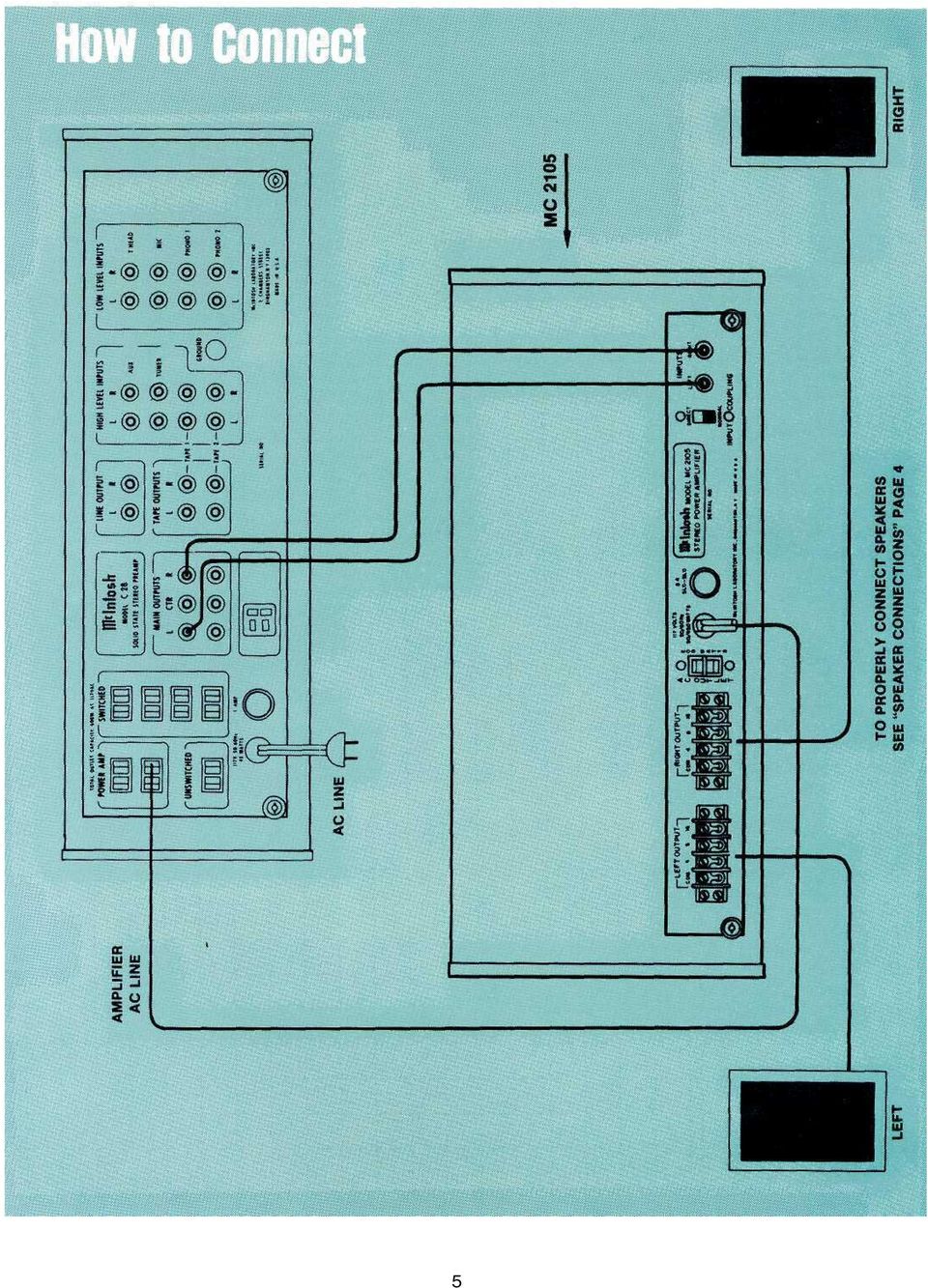
6 HOW to Connect INPUT STEREO The shielded cable from the left output of the Mclntosh preamplifier is plugged into the left jack. The shielded cable from the right output of the Mclntosh preamplifier is plugged into the right jack. SPEAKERS Speakers are connected at the barrier strips marked OUTPUT on the back panel of the amplifier. Use lamp cord, bell wire, or wire with similar type of insulation to connect the speakers to the amplifier. For the normally short distances of under 50 feet between the amplifier and speaker, #18 wire or larger can be used. For distances over 50 feet between the amplifier and speaker use larger wire. The loudspeaker impedance is usually identified on the loudspeaker itself. Connect one of the leads from the left loudspeaker to the screw marked COM on the LEFT OUTPUT barrier strip. Connect the other lead from the left loudspeaker to the screw marked with the number corresponding to the speaker impedance on the LEFT OUTPUT barrier strip. Connect one of the leads from the right loudspeaker to the screw marked COM on the RIGHT OUTPUT barrier strip. Connect the other lead from the right loudspeaker to the screw marked with the number corresponding to the speaker impedance on the RIGHT OUTPUT barrier strip. The only adverse effect on the operation of a Mclntosh amplifier when it is improperly matched is a reduction in the amount of distortion-free power available to the loudspeaker. Close impedance matching is desirable for maximum distortion-free power. SPEAKER CONNECTIONS Use this table to determine proper speaker connection. Connect the If the speaker impedance speaker leads is between: between COM and: 3.2 to 6.5 ohms 4 ohms 6.5 to 13 ohms 8 ohms 13 to 26 ohms 16 ohms Connect as follows: Connect one right speaker Connect one left speaker to screw LEFT- COM and other to: If the speaker imped- ance is: 4 ohms LEFT-4 8 ohms LEFT-8 16 ohms LEFT-16 lead to the screw marked RIGHT-COM and the other to: RIGHT-4 RIGHT-8 RIGHT-16 DO NOT CONNECT A MONOPHONIC LOUD- SPEAKER TO BOTH TERMINALS. THE LOUD- SPEAKER CAN BE DAMAGED. For 25 volt line operation connect one of the left leads to the screw marked COM on the LEFT OUT- PUT barrier strip. The other left lead is connected to the screw marked 8W on the LEFT OUTPUT barrier strip. Connect the right leads in the same manner on the RIGHT OUTPUT barrier strip. AC POWER: The MC 2105 operates on 117 to 130 volt, 50/60 Hz. The amplifier will be turned on and off if its power cord is plugged in one of the auxiliary AC power outlets on the program source. 4

7 5
8 HOW to Use the Dynamic Peak Locking Meters Ordinary meters lack the capability of indicating the short interval power in a sound wave. The mass of the meter movement is too great to respond to instantaneous changes in music program material. Mclntosh superior engineering has developed new circuitry that permits the meters on the MC 2105 to respond to the short interval power in a sound wave to an accuracy of 98% of the true value. This is another Mclntosh development that represents a major step forward in the use of power level meters. There are two circuits that give these meters the indicating capability of the short interval power in a sound wave. The first circuit is an accelerating circuit that compensates for the inertia characteristics of the meter movement. Because the short interval power fluctuation is so rapid, the eye might not perceive the instantaneous power reading. This caused the development of the second circuit, which is a "time stretching" circuit. The time stretching circuit delays the movement of the meter needle at peak reading for a few milliseconds. With the aid of the CBS test record STR1000 the frequency response of your phono cartridge can be measured. The graph on page 7 shows the ideal RIAA curve using the CBS record STR100. Follow these steps to plot the performance of your phonograph cartridge. A tape recorder can be checked in the same fashion. 1. Use a standard frequency response tape as the signal source. 2. Complete all steps outlined for phono cartridges. 3. You now have a graph of the playback characteristics of your tape recorder. To find the record characteristics of the tape recorder follow this procedure: 1. Record the CBS Test Record STR1000 on your tape recorder. Adjust the record volume only on the 1000 Hz signal for proper recording level. DO NOT ADJUST THE RECORD VOLUME CONTROL DURING THE RECORD- ING. 2. Play back the tape just recorded. Complete all steps outlined for tape playback characteristics. 3. A comparison of the two curves will give the recording characteristics of your tape recorder. A deviation of 3 db is acceptable. Similar checks can be made on all program sources in your stereo system. Follow the same general procedure for any program source for which a standard reference is available. 1. Set the "METER RANGE SWITCH" to the -20 position. 2. Play the 1000 Hz test tone recorded on the CBS Test Record STR100 on your phonograph. 3. Turn the LEFT GAIN control until the left meter indicates "0." 4. Turn the RIGHT GAIN control until the right meter indicates "0." 5. Write down the meter indication at each frequency as the record plays. 6. Transfer the readings by frequency to the graph. 7. The graph shows the ideal RIAA response curve using the CBS STR1000 test record. Compare your curve with the curve on the graph. A deviation of 3 db from the ideal is acceptable. By making this check at regular intervals, (for instance, every 6 months) any deterioration in the cartridge or system will be quickly detected. 6

9 IDEAL RIAA SYSTEM RESPONSE USING CBS STR 100 TEST RECORD ,000 10, , RELATIVE OUTPUT LEVEL IN db RELATIVE OUTPUT LEVEL IN db ,000 10, ,000 FREQUENCY IN Hz 7

10 Front Panel information LEFT GAIN Use the left gain control to adjust the volume in the left channel to the desired listening level. Turn the control clockwise to increase the volume. RIGHT GAIN Use the right gain control to adjust the volume in the right channel to the desired listening level. Turn the control clockwise to increase the volume. METER RANGE The meter switch has four positions. The first position is OFF. With the switch in the OFF position there is no indication on the meters. -0 In this position of the meter range switch, the amplifier will deliver 100 watts when the meter indicates +3dB, with meter indication of "0", the amplifier delivers 50 watts, with a meter indication of 3dB, -10 In this position of the meter range switch, the amplifier will deliver 5 watts output when the meter indicates "0". With a meter indication of 3dB, the amplifier delivers 2½ watts output and a -10dB meter indication, the amplifier delivers ½ watt. -20 In this position of the meter range switch, the amplifier will deliver ½ watt (500 milliwatts) when the meter indicates "0". With a meter indication of 3dB, the amplifier delivers ¼ watt (250 milliwatts) and a -10dB meter indication the amplifier delivers 50 milliwatts. the amplifier delivers 25 watts; and a meter indication of -10dB, the amplifier delivers 5 watts. (A meter reading of +3.2dB indicates 105 watts power output.) HEADPHONE Use the jack for low impedance stereo headphones. The headphone jack is on at all times. SPEAKERS OFF: The loudspeakers are turned off when the SPEAKER switch is in the OFF position. You can listen to headphones in private. THIS SWITCH MUST BE IN THE "ON" POSITION TO HEAR MUSIC FROM THE LOUDSPEAKERS. ON: Music will be heard through the loudspeakers. Use this as the normal listening position. POWER The power switch turns the MC2105 on or off. The switch does not control the power outlet on the back panel. If you wish to control the operation of the on/off switch from a preamplifier control center leave the switch in the ON position. In this case be sure to plug the AC cord of the MC 2105 into the controlled outlets on the rear of the preamplifier control center. OFF: In the OFF position the AC to the amplifier is turned off. 8

11 Performance Limits and Ratings PERFORMANCE GUARANTEE Performance Limits are the maximum deviation from perfection permitted for a Mclntosh instrument. We promise you that the MC 2105 you buy must be capable of performance at or exceeding these limits or you get your money back. McIntosh is the only manufacturer that make this guarantee. PERFORMANCE McIntosh audio power ratings are in accordance with the Federal Trade Commission Regulation of November 4, 1974 concerning power output claims for amplifiers used in home entertainment products, POWER OUTPUT 105 watts minimum sine wave continuous average power output, per channel, both channels operating into 4 ohms, 8 ohms, or 1.6 ohms load impedance, which is: 20.5 volts RMS across 4 ohms 29.0 volts RMS across 8 ohms 41.0 volts RMS across 16 ohms OUTPUT LOAD IMPEDANCE 4 ohms, 8 ohms, or 16 ohms; separate terminals are provided for each output RATED POWER BAND 20 Hz to 20,000 Hz TOTAL HARMONIC DISTORTION 0.25% maximum harmonic distortion at any power level from 250 milliwatts to 105 watts per channel from 20 Hz to 20,000 Hz, both channels operating INTERMODULATION DISTORTION 0.25% if instantaneous peak power output is 210 watts or less per channel with both channels operating for any combination of frequencies 20 Hz to 20,000 Hz FREQUENCY RESPONSE 20 Hz to 20,000 Hz db 10 Hz to 100,000 Hz db at one watt output NOISE AND HUM 90 db below rated output OUTPUT POWER MONITOR METER Meter is calibrated to read +3 db when amplifier produces 105 watts. Meter range switch is provided to increase meter sensitivity by 10 db or 20 db Calibration accuracy at 0 db reading is ±2% at all frequencies; meter range accuracy is ±5% RATINGS OUTPUT VOLTAGES 25 volts for distribution lines DAMPING FACTOR 13 at 8 ohms output 18 at 4 ohms output 10 at 16 ohms output INPUT IMPEDANCE ohms INPUT SENSITIVITY 0.5 volt. Level control provided for higher input voltage GENERAL INFORMATION POWER REQUIREMENTS 120 volts Hz, 75 watts at zero signal output, 430 watts at rated output SEMICONDUCTOR COMPLEMENT 34 silicon transistors 18 silicon rectifiers and diodes MECHANICAL INFORMATION SIZE Front panel measures 16 3/16 inches wide (41,12 cm) by 71/8 inches high (18,1 cm). Chassis measures 15 inches wide (38,1 cm) by 6 9/16 inches high (16.67 cm) by 14½ inches deep (36.83 cm), including connectors. Knob clearance required is 1½ inches (3.81 cm) in front of mounting panel FINISH Front panel is anodized gold and black with special gold teal nomenclature illumination. Chassis is chrome and black MOUNTING Exclusive Mclntosh developed professional PANLOC WEIGHT 65 pounds (29.48 kg) net, 77 pounds (34,93 kg) in shipping carton SPECIAL FEATURES The amplifier is completely stable when connected to any loudspeaker system or even to any reactive loads; The MC 2105 has special circuits to prevent damage by short circuit or open circuit of the output loads, or by any amount of output impedance mismatch, Thermal cutouts are mounted on the output transistor heat sinks to provide protection in the event of inadequate ventilation. Peak reading - peak locking meters feature special circuit to respond to peak value of complex input signal. 9

12

13 Technical Description A two stage amplifier with three transistors in each channel increases the input voltage 16 db. There are 13 transistors in each power amplifier section. The two stage preamplifier is fed to a pair of matched transistors arranged as an emitter coupled amplifier with two inputs and one output. The signal from the preamplifier section connects to one of these inputs. Both AC and DC negative feedback are applied to the other input. This large quantity of feedback is used to reduce noise and distortion. The signal is then fed to a voltage amplifier. The voltage amplifier is followed by two driver transistors. The output section is arranged as a series pushpull amplifier. The power transistors used in the output section of your MC 2105 are selected for their high power dissipation capability, wide frequency response, and large "safe operating area." In addition, each power transistor is given four separate tests before it is put in your MC This additional testing makes sure your MC 2105 will deliver its rated power from 20 to 20 khz with low distortion and complete reliability. The power transistors are mounted on oversized anodized heat sinks. The heat sinks assure that under normal operation the transistors will operate at a low temperature. If temperatures increase due to a shorted speaker, or restricted ventilation, an automatic temperature sensing device turns off the MC The device operates automatically at a preset temperature. The MC 2105 will turn on again when the temperature has returned to normal limits. This additional feature gives your MC 2105 complete reliability under the most extreme operating conditions. The output stages are matched to the load by the Mclntosh autoformer. The Mclntosh autoformer is carefully wound using Mclntosh trifilar winding and interleaving techniques. Trifilar winding and interleaving gives the transformers exceptional bandwidth. The autoformers properly match the power transistors to 4, 8, and 16 ohm loads at all audio frequencies. The use of the Mclntosh designed trifilar autoformer makes the Mclntosh solid state amplifiers the only amplifiers that deliver FULL POWER AT ALL SPEAKER IMPEDANCES. You have not been power penalized for your choice of loudspeakers when using the Mclntosh MC Another of the advantages of the autoformers is the 25 volt output for a constant voltage distribution system. With the MC 2105 several sets of speakers can be operated independently throughout your home. To further insure reliability a special power output SENTRY MONITORING CIRCUIT prevents failure of the power output transistors due to excessive mismatch of the output. When your MC 2105 operates normally the SENTRY MONITORING CIR- CUIT has no effect on signals passing through the power amplifier. If the power dissipation should rise above normal operation, the SENTRY MONI- TORING CIRCUIT restricts the drive to the output transistors. The SENTRY MONITORING CIRCUIT acts instantaneously for any input signal or load combination. This arrangement assures complete circuit reliability. Only Mclntosh gives you this degree of protection. POWER SUPPLY SECTION There are three separate power supply sections. One positive and one negative high current supply is used for the output stages. The other positive supply is used for the driving amplifier stages. All supplies are full wave and use silicon rectifiers. Adequate filtering is used to assure an absolute minimum of hum. The power output stage filter capacitors have very high capacity, which allows full power output below 20 Hz. The power transformer is generous in size and runs cool, even under heavy use. 11

14 Block Diagram 12

15

16 MCINTOSH LABORATORY INC. 2 CHAMBERS ST., BINGHAMTON, N. Y Design subject to change without notice. Printed in U.S.A

THE MclNTOSH MC 2100 SOLID STATE STEREO POWER AMPLIFIER
 THE MclNTOSH MC 2100 SOLID STATE STEREO POWER AMPLIFIER Price $1.25 Your MC 2100 stereo amplifier will give you many years of pleasant and satisfactory performance. If you have any questions concerning
THE MA 6200 INTEGRATED AMPLIFIER
 THE MA 6200 INTEGRATED AMPLIFIER Reading Time: 40 Minutes Price: $2.00 VARIOUS REGULATORY AGENCIES REQUIRE THAT WE BRING THE FOLLOWING INFOR- MATION TO YOUR ATTENTION. PLEASE READ IT CAREFULLY. WARNING:
MODEL 2202IQ (1991-MSRP $549.00)
") F O R T H E L O V E O F M U S I C F O R T H E L O V E O F M U S I C MODEL 2202IQ (1991-MSRP $549.00) OWNER'S MANUAL AND INSTALLATION GUIDE INTRODUCTION Congratulations on your decision to purchase a LINEAR
F O R T H E L O V E O F M U S I C F O R T H E L O V E O F M U S I C MODEL 2202IQ (1991-MSRP $549.00) OWNER'S MANUAL AND INSTALLATION GUIDE INTRODUCTION Congratulations on your decision to purchase a LINEAR
TOA 900 SERIES II MIXER POWER AMPLIFIER
 Operating Instructions TOA 900 SERIES II MIXER POWER AMPLIFIER A-903MK2 A-906MK2 A-912MK2 TO REDUCE THE RISK OF ELECTRICAL SHOCK, DO NOT REMOVE COVER. NO USER SERVICEABLE PARTS INSIDE. REFER SERVICING
MPA-101. WARNING: Improper installation could result in damage to the amplifier and/or speakers. Read all instructions before installation.
 MPA-101 WARNING: Improper installation could result in damage to the amplifier and/or speakers. Read all instructions before installation. The lightning flash with arrowhead, within an equilateral triangle,
Hegel H1 High End Integrated Amplifier
 Hegel H1 High End Integrated Amplifier www.hegel.com info@hegel.com USER GUIDE Congratulations on your new HEGEL! Our products are based on a simple philosophy: The component shall reproduce the original
STEREO PREAMPLIFIER INSTRUCTIONS FOR USE
 XX STEREO PREAMPLIFIER INSTRUCTIONS FOR USE Thank you for purchasing the Musical Fidelity A5 CR Preamplifier. Used properly and carefully, it should give many years of outstanding musical reproduction.
Brio-Rmanual:Cursamanual.qxd 08/04/2011 09:25 Page1
 - Brio-Rmanual:Cursamanual.qxd 08/04/2011 09:25 Page1 Brio-Rmanual:Cursamanual.qxd 08/04/2011 09:25 Page2 CONTENTS INTRODUCTION, FEATURES AND TECHNOLOGY 1-3 INSTALLATION 3 CONNECTIVITY 4-6 LOUDSPEAKER
LOXONE 12 Channel Amplifier
 LOXONE 12 Channel Amplifier Item no.: 200110 Thank you for purchasing the Loxone Twelve Channel Amplifier. The versatility of the Amplifier makes it the perfect choice for almost every type of custom multi-room
WOO AUDIO WA3. Stereo Headphone Amplifier. Single-Ended OTL, Class A Vacuum Tube Headphone & Pre Amplifier. Owner s Manual
 WOO AUDIO WA3 Stereo Headphone Amplifier Single-Ended OTL, Class A Vacuum Tube Headphone & Pre Amplifier Owner s Manual Please review this manual before operating your WOO AUDIO product. Inc. All rights
MC300 POWER AMPLIFIER
 MC300 POWER AMPLIFIER MC300 POWER AMPLIFIER IMPORTANT SAFETY INSTRUCTIONS THESE INSTRUCTIONS ARE TO PROTECT YOU AND THE MclNTOSH INSTRUMENT. BE SURE TO FAMILIARIZE YOURSELF WITH THEM Copyright 1995 by
BXR. Owner, s Manual. One hundred BASS EXTENDED RANGE P/N 040695
 THE SOUND THAT CREATES LEGENDS BASS EXTENDED RANGE BXR One hundred Owner, s Manual P/N 040695 BXR 100 Owner s Manual Congratulations on your purchase of the Fender BXR 100 Bass amplifier. The Fender BXR
Perseus. Owner s Manual. Vacuum Tube Preamplifier. Rogue Audio, Inc. 3 Marian Lane Brodheadsville, PA 18322. Issue date: 02/01/06
 Perseus Vacuum Tube Preamplifier Owner s Manual Rogue Audio, Inc. 3 Marian Lane Brodheadsville, PA 18322 Issue date: 02/01/06 TABLE OF CONTENTS 1) Introduction 2 2) Unpacking the Perseus Preamplifier 2
KEYBOARD EXTENDED RANGE. Sixty Owner, s Manual P/N 049254
 THE SOUND THAT CREATES LEGENDS KEYBOARD EXTENDED RANGE Sixty Owner, s Manual P/N 049254 INTRODUCTION Your new Fender KXR 60 Keyboard Amplifier is the result of Fender s ongoing dialog with many of today
INTRODUCTION. Please read this manual carefully for a through explanation of the Decimator ProRackG and its functions.
 INTRODUCTION The Decimator ProRackG guitar noise reduction system defines a new standard for excellence in real time noise reduction performance. The Decimator ProRackG was designed to provide the maximum
Amplifier: AMP-8125. Feature Summary
 Savant Systems AMP-825 is a multi-room amplifier for distributed audio applications. The AMP-825 is an ultraefficient Class D amplifier delivering 8 channels of reliable amplification rated at 25 watts
IMPORTANT SAFETY INSTRUCTIONS
 IMPORTANT SAFETY INSTRUCTIONS When using this electronic device, basic precautions should always be taken, including the following: 1. Read all instructions before using the product. 2. Do not use this
Rack Installation. Unpacking the System. Choosing a Setup Location. General Server Precautions. Barracuda Appliances
 This set of instructions applies to racking and rail kit installation for 6XX and above. The Rack Mounting Instructions section below provides information on installing the SC825 chassis into a rack unit
Kit 106. 50 Watt Audio Amplifier
 Kit 106 50 Watt Audio Amplifier T his kit is based on an amazing IC amplifier module from ST Electronics, the TDA7294 It is intended for use as a high quality audio class AB amplifier in hi-fi applications
INSTRUCTIONS FOR USE Pro-Ject Tube Box S
 INSTRUCTIS FOR USE Pro-Ject Tube Box S Dear music lover, thank you for purchasing a PRO-JECT AUDIO phono amplifier. In order to achieve maximum performance and reliability you should study these instructions
How To Connect A Music Source To A Cartridge
 Lucent Technologies Bell Labs Innovations CIB 2871 (151A) Music-On-Hold/Paging Cartridge Type II (6102) (103979977) CIB 2871 Comcode 103979977 Issue 4 January 1997 CIB 2871 (151A) Music-On-Hold/Paging
Tone Hammer 500. Owners Manual. Manual Version 1.0
 Tone Hammer 500 Owners Manual Manual Version 1.0 1. Incorporating the preamp from the popular Tone Hammer preamp/di pedal this superlight bass head combines three bands of flexible EQ, a colorful "Drive"
Owner s Manual AWM910 JENSEN AWM910 COMPACT DISC PLAYER RADIO CD COMPACT MUSIC SYSTEM MUTE AUX BAND AUX IN PUSH PUSH PWR VOL ALARM T/F AUD SPK A SPK B
 AWM910 Owner s Manual COMPACT DISC PLAYER PUSH 1 2 3 4 5 6 RPT SCAN RDM H M PUSH PWR VOL ALARM SET ON/OFF EQ T/F AUD RADIO CD COMPACT MUSIC SYSTEM MUTE AUX BAND CD AUX IN A B A+B JENSEN AWM910 Thank You!
REALISTIC Stereo Three AM/FM Radio (120-1451) Features Faxback Doc. # 18906
 Features Faxback Doc. # 18906") REALISTIC Stereo Three AM/FM Radio (120-1451) Features Faxback Doc. # 18906 Your REALISTIC Stereo Three is a complete solid-state 3-piece FM/AM Stereo System. Its size and styling will fit well in any
REALISTIC Stereo Three AM/FM Radio (120-1451) Features Faxback Doc. # 18906 Your REALISTIC Stereo Three is a complete solid-state 3-piece FM/AM Stereo System. Its size and styling will fit well in any
Active Speaker System LX523 AUDAC PROFESSIONAL AUDIO EQUIPMENT. Active Speaker System with remote input LX523. User Manual & Installation Guide
 Active Speaker System LX523 AUDAC PROFESSIONAL AUDIO EQUIPMENT Active Speaker System with remote input LX523 User Manual & Installation Guide AUDAC PROFESSIONAL AUDIO EQUIPMENT User Manual & Installation
C220 PRELIMINARY TUBE PREAMPLIFIER SERVICE MANUAL. SERIAL NO. WS1001 And Above C220. Serial Number W S1001 And Above CONTENTS
 Performance Specifications... 2 Notes... 2 Rear Panel... 3 Section Location... 3 Block Diagram... 5-6 Interconnection Diagram... 7-8 Main Schematic and PCB... 9-18 C220 TUBE PREAMPLIFIER CONTENTS Display
AU-110 racking guide NBXPN: 023
 AU-110 racking guide NBXPN: 023 1. Overview NIMBOXX AU-110 Rack Installation This guide provides setup instructions for installing your NIMBOXX AU-110 in a rack. Following these steps in the order given
BXR 300C BXR 300R. Owner, s Manual P/N 040294
 THE SOUND THAT CREATES LEGENDS BXR 300C BXR 300R Owner, s Manual P/N 040294 INTRODUCTION The Fender BXR 300 AMPLIFIER is the most recent effort in state of the art bass amplifier technology, and is a member
Gemini II. Subwoofer System OWNERS MANUAL
 Gemini II Subwoofer System OWNERS MANUAL CONTENTS Page No. 1) Safety instructions. 2) 3) 4) Connecting up your Gemini II. Connecting up using the high level input. Connecting up using the low level input.
The Bose 601 TM Series IV Direct/Reflecting Speaker System
 The Bose 601 TM Series IV Direct/Reflecting Speaker System Owner s Guide October 25, 2001 AM257731_00_V.pdf Customer Information Declaration of Conformity We, the offerer: Bose Corporation, The Mountain,
POWERED MIXERS. From Fender Pro Audio. Owner's Manual for SRM 6302 / 8302 P/N 050804 REV A
 POWERED MIXERS From Fender Pro Audio 6 3 0 2 / 8 3 0 2 Owner's Manual for SRM 6302 / 8302 P/N 050804 REV A Fender Musical Instruments 7975 North Hayden Road, Scottsdale, Arizona 85258 U.S.A. Fender knows
ECI1 DUAL MONO INTEGRATED AMPLIFIER
 ECI1 DUAL MONO INTEGRATED AMPLIFIER Owner s Manual WARNING: To reduce risk of fire or electric shock, do not expose this appliance to rain or moisture. Verify line voltage before use. Do not remove cover.
Owner s Manual Please read before using this equipment. 4-Channel Stereo Mixer
 Owner s Manual Please read before using this equipment. 4-Channel Stereo Mixer ˆ Features Your RadioShack 4-Channel Stereo Mixer is a sophisticated desktop control center, perfect for mixing sound on four
SPEAKER SELECTION SYSTEM
 M O D E L SPS-4 SPS-4 SPEAKER SELECTION SYSTEM NILES INSTALLATION & OPERATION GUIDE SPS-4 Speaker Selection System TABLE OF CONTENTS Introduction 1 Features and Benefits 2 Installation Considerations 4
Achat 115MA full-range speaker. user manual
 Achat 115MA full-range speaker user manual Musikhaus Thomann Thomann GmbH Hans-Thomann-Straße 1 96138 Burgebrach Germany Telephone: +49 (0) 9546 9223-0 E-mail: info@thomann.de Internet: www.thomann.de
OWNER'S MANUAL. AtlasSound.com PA601 COMMERCIAL AMPLIFIER. PA601 Commercial Amplifier. Power. Master
 Signal Peak Power Power On Off Master PA601 Commercial Amplifier TABLE OF CONTENTS Safety Instructions.....2 Introduction, Features, and Applications......3 Safety Precautions.........4 Front Panel Description......6
Hegel H80 High End Integrated Amplifier. User manual
 Hegel H80 High End Integrated Amplifier User manual USER GUIDE Congratulations on your new HEGEL H80! All Hegel products are based on a simple philosophy: The audio reproduction instrument shall reproduce
Congratulations! Thank you!
 TM-47 ORDERCODE D1370 Congratulations! You have bought a great, innovative product from DAP Audio. The DAP Audio Microphone range brings excitement to any venue. Whether you want simple plug-&-play action
Powered Subwoofer. Owner s Manual 2013 PINNACLE LOUDSPEAKERS
 Powered Subwoofer Owner s Manual 2013 PINNACLE LOUDSPEAKERS We congratulate and thank you for choosing a PINNACLE subwoofer. Our subwoofers exemplify the best in modern audio technology, and are designed
GLOLAB Universal Telephone Hold
 GLOLAB Universal Telephone Hold 1 UNIVERSAL HOLD CIRCUIT If you have touch tone telephone service, you can now put a call on hold from any phone in the house, even from cordless phones and phones without
************* OWNER'S MANUAL BAMF800/2 BAMF1250/2 BAMF1800/2 BAMF2200/2 BAMF2600/2 BAMF1200/4 BAMF1600/4 BAMF2000/1D BAMF4000/1D BAMF5500/1D
 ************* OWNER'S MANUAL BAMF800/2 BAMF1250/2 BAMF1800/2 BAMF2200/2 BAMF2600/2 BAMF1200/4 BAMF1600/4 BAMF2000/1D BAMF4000/1D BAMF5500/1D INTRODUCTION Power Acoustik amplifiers provide high-performance
Digital FM/AM Receiver
 Digital FM/AM Receiver Model RM-350D User s Guide 54-5021-01 9609 Printed in USA Specifications Band Coverage............ AM.....................530-1620KHz FM......................87.5-107.9MHz Tuning....................PLL
2 Ohm Nominal Coaxial Speaker OWNER S MANUAL
 2 Ohm Nominal Coaxial Speaker OWNER S MANUAL 1 page 1 SPL 65 Coaxial Speaker Congratulations on your purchase of the Soundstream SPL 65 Coaxial Speaker. When used with a high quality 2 ohm rated power
EC4.8. BalancedReferencePreamplifier. Owner smanual ENG
 EC4.8 BalancedReferencePreamplifier Owner smanual ENG Unpacking the EC 4.8 Immediately upon receipt of the EC 4.8, inspect the carton for possible damage during shipment. The carton and packaging have
ACTIVE. www.edgecaraudio.com
 ACTIVE www.edgecaraudio.com INTRODUCTION This instruction manual is for your safety and must be adhered to at all times. Please read and ensure that you fully understand the installation and set up procedures
EVID Compact Sound Speaker System
 EVID Compact Sound Speaker System EVID-C44, EVID-C2.1, EVID-40C, EVID-S44, EVID-S44W, EVID-2.1, EVID-2.1W, EVID-40S, and EVID-40SW en Installation Manual en 3 Table of contents 1 Safety 4 2 Welcome 6
INSTALLATION & OPERATION GUIDE. Systems Integration Amplifier
 INSTALLATION & OPERATION GUIDE Systems Integration Amplifier B L E N D I N G H I G H F I D E L I T Y A N D A R C H I T E C T U R E CONGRATULATIONS! Thank you for purchasing the Niles SI-245, one of the
How To Use The Gr8A Power Amplifier
 GR8A 8 Channel Amplifier USER GUIDE Publication AP4298 Limited One Year Warranty This product has been manufactured in the UK by ALLEN & HEATH and is warranted to be free from defects in materials or workmanship
PERSONAL MONITOR MIXER/HEADPHONE AMP. S Class Signal Processors
 PERSONAL MONITOR MIXER/HEADPHONE AMP S Class Signal Processors Table Of Contents Features 3 Front and Rear Panel Layout 4 Operating the S monitor 5-7 Specifications 8 Wiring Guide 8 Copyright 2003, Samson
PS 29M DUAL CHANNEL BELTPACK IN METAL CASE
 PS 29M DUAL CHANNEL BELTPACK IN METAL CASE USER MANUAL October 2013 This product is designed and manufactured by: ASL Intercom BV Zonnebaan 42 3542 EG Utrecht The Netherlands Phone: +31 (0)30 2411901 Fax:
AW-100 DUAL MONO BALANCED POWER AMPLIFIER. Owner s Manual
 AW-100 DUAL MONO BALANCED POWER AMPLIFIER Owner s Manual WARNING: To reduce risk of fire or electric shock, do not expose this appliance to rain or moisture. Verify line voltage before use. Do not remove
6.101 Final Project Report Class G Audio Amplifier
 6.101 Final Project Report Class G Audio Amplifier Mark Spatz 4/3/2014 1 1 Introduction For my final project, I designed and built a 150 Watt audio amplifier to replace the underpowered and unreliable
The audio input connection on your computer
 This page helps you to connect your audio equipment to your PC so you can start using the xxxxxxx Sound Recorder and Editor and get your recordings to CD or MP3. You can use our software to digitize music
CINEMA SB100 powered soundbar speaker
 CINEMA SB100 powered soundbar speaker quick-start guide Thank You For Choosing This JBL Product The JBL Cinema SB100 powered soundbar speaker is a complete, integrated sound system that will dramatically
XLS200 MKII. Subwoofer System OWNERS MANUAL
 XLS200 MKII Subwoofer System OWNERS MANUAL CONTENTS Page No. 1) Safety instructions. 2) 3) 4) Connecting up your XLS200. Connecting up using the high level input. Connecting up using the low level input.
BeoLab 1. User s guide
 BeoLab 1 User s guide Legal notice: CAUTION RISK OF ELECTRIC SHOCK DO NOT OPEN CAUTION: To reduce the risk of electric shock, do not remove cover (or back). No User-serviceable parts inside. Refer servicing
CELO5. User & Installation Manual. www.audac.eu
 CELO5 User & Installation Manual www.audac.eu 2 Introduction 5 High-end Slim Ceiling Speaker The CELO5 is the 5 version of AUDAC s CELO High-end Slim ceiling speaker series with an RMS power of 50 Watt
PLA-4350. PLA-4300D Class-D Mono Block Power Amplifier. Two Channel High Performance Power Amplifier. Four Channel High Performance Power Amplifier
 PLA- 2 1 9 PLA-2250 PLA-2450 PLA-2650 PLA-2150 PLA-2350 PLA-2550 PLA-2750 PLA-2850 Two Channel High Performance Power Amplifier PLA- 4 1 9 PLA-4250 PLA-4150 PLA-4350 Four Channel High Performance Power
1 All safety instructions, warnings and operating instructions must be read first.
 ONYX USER MANUAL 2 Dateq ONYX Manual Safety instructions EN Safety instructions 1 All safety instructions, warnings and operating instructions must be read first. 2 All warnings on the equipment must be
F25 REMOTE CONTROL STEREO PREAMPLIFIER INSTRUCTIONS FOR USE
 REMOTE CONTROL STEREO PREAMPLIFIER INSTRUCTIONS FOR USE Thank you for purchasing the Musical Fidelity Preamplifier. Used properly and carefully, it should give you many years of outstanding musical reproduction.
Safety Warnings and Guidelines
 Safety Warnings and Guidelines Thank you for purchasing this Wireless Speaker Amplifier! For best results, please thoroughly read this manual and carefully follow the instructions. Please pay extra attention
Owner s Manual 900.4. 4 channel amplifier
 Owner s Manual 900.4 4 channel amplifier THANK YOU Limited Warranty: for purchasing RE AUDIO Bluetooth amplifiers BT-900.4. With almost no sacrifice on sound quality, BT-900.4 easily plays the music from
SYSTEM MIX PLUS. Owner's Manual DIGITAL MUSIC CORPORATION
 SYSTEM MIX PLUS Owner's Manual 1 Table of Contents 1. Introduction.................. 2 1.1 Overview 1.2 Unpacking 2. Operation................... 3 2.1 Front Panel 2.2 Rear Panel 3. Mixer.....................
LS-1 Series Tungsten Halogen Light Sources Installation and Operation Instructions
 LS-1 Series Tungsten Halogen Light Sources Installation and Operation Instructions Description The LS-1 Series of tungsten halogen light sources are versatile, white-light lamps optimized for use in the
HP UPS R1500 Generation 3
 HP UPS R1500 Generation 3 Installation Instructions Part Number 650952-001 NOTE: The rating label on the device provides the class (A or B) of the equipment. Class B devices have a Federal Communications
TELIKOU Intercom System. MS-500(4+1 channel) Main Station Instruction Manual
 Main Station Instruction Manual") TELIKOU Intercom System MS-500(4+1 channel) Main Station Instruction Manual TELIKOU Systems All Rights Reserved While TELIKOU makes every attempt to maintain the accuracy of the information contained in
TELIKOU Intercom System MS-500(4+1 channel) Main Station Instruction Manual TELIKOU Systems All Rights Reserved While TELIKOU makes every attempt to maintain the accuracy of the information contained in
SM-1000. Audio Mixer with Echo (Rack Mount Type) OWNER S MANUAL. Cat. No. 32-3001. Please read before using this equipment.
 OWNER S MANUAL. Cat. No. 32-3001. Please read before using this equipment.") 32-3001.fm Page 1 Tuesday, August 10, 1999 8:02 AM Cat. No. 32-3001 OWNER S MANUAL Please read before using this equipment. SM-1000 Audio Mixer with Echo (Rack Mount Type) 32-3001.fm Page 2 Tuesday, August
32-3001.fm Page 1 Tuesday, August 10, 1999 8:02 AM Cat. No. 32-3001 OWNER S MANUAL Please read before using this equipment. SM-1000 Audio Mixer with Echo (Rack Mount Type) 32-3001.fm Page 2 Tuesday, August
PRO MPA II. ART PRO MPA II Microphone Preamplifier USER S GUIDE
 PRO MPA II ART PRO MPA II Microphone Preamplifier USER S GUIDE IMPORTANT SAFETY INSTRUCTIONS READ FIRST This symbol, wherever it appears, alerts you to the presence of uninsulated dangerous voltage inside
THE FISHER K-10 Dynamic SPACEXPANDER@ Reverberation Unit
 THE FISHER K-10 Dynamic SPACEXPANDER@ Reverberation Unit The FISHER Spacexpander adds a new dimension -reverberation -to most stereophonic (or monophonic) home music systems Natural reverberation is created
Stage 112. Owner, s Manual P/N 039080
 THE SOUND THAT CREATES LEGENDS Stage 112 Owner, s Manual P/N 039080 Standard Strat / General Purpose / Any Position Try this: On Me Drive Channel for a real bluesy sound, use Me neck pick- up with Me guitar
Contents. Safety Warnings... 1
 Contents Safety Warnings... 1 Unpacking the GQ600... 1 Introduction... 2 GQ600 Filter Characteristics... 2 1/3 Octave Centre Frequencies... 4 Front Panel Functions... 5 Rear Panel Functions... 6 Specifications...
COMPANION 20 MULTIMEDIA SPEAKER SYSTEM. Owner s Guide Guía de usuario Notice d utilisation
 COMPANION 20 MULTIMEDIA SPEAKER SYSTEM Owner s Guide Guía de usuario Notice d utilisation Safety and Regulatory Information Please read this owner s guide Please take the time to follow the instructions
Price List - including VAT - Effective October 2015 - US$ Pricing is excluding tax
 PAG 1/8 PREAMPLIFIERS - Class A FET Preamplifier 07X FET Phono Preamplifier 06X The Preamplifier 07X is Coda s flagship preamplifier, offering distortion-free preamplification and unsurpassed sonic performance
INSTALLATION GUIDE. Freestanding Subwoofer
 INSTALLATION GUIDE RCC300-SM RCC300-FS RCC300-SA RCC300-CM Subwoofer Module Freestanding Subwoofer Subwoofer Amplifier Cabinet Mount 2 Thank you for choosing Artison s RCC 300 Subwoofer System. We are
WARNING! REQUIRED TOOLS & SUPPLIES: HIGH VOLTAGE
 INSTRUCTIONS Product: GEM Electric Motorcars Models: All Subject: Instructions for installing Stereo Accessory Estimated Completion Time:.75 Hours Parts: See Page # 7 REQUIRED TOOLS & SUPPLIES: (1) 3/8
THE MCINTOSH MAC 4100 RECEIVER
 THE MCINTOSH MAC 4100 RECEIVER Reading Time: 48 Minutes Price $2.00 VARIOUS REGULATORY AGENCIES REQUIRE THAT WE BRING THE FOLLOWING INFOR- MATION TO YOUR ATTENTION. PLEASE READ IT CAREFULLY. WARNING: TO
Operation Manual for Users
 Operation Manual for Users Model No.: FLTAMFMRCD!!!!!!!!!! ATTENTION!!!!!!!!!! THE RESET BUTTON MUST BE PRESSED TO ENSURE PROPER OPERATION. SEE INSTRUCTION MANUAL Table of Contents Table of Contents ---------------------------------------------------------------------------------------------
USA 305. Power Amplifier OWNERS MANUAL AND INSTALLATION GUIDE PARALLEL/SERIES WIRING DIAGRAMS. two 4 ohm woofers in parallel = 2 ohms
 PARALLEL/SERIES WIRING DIAGRAMS USA 305 two 4 ohm woofers in parallel = 2 ohms two 4 ohm woofers in series = 8 ohms SOUNDSTREAM TECHNOLOGIES 120 Blue Ravine Road Folsom California 95630 USA ph 916.351.1288
AM/FM Component Stereo Receiver System (120-1470) Preparation Faxback Doc. # 18708
 Preparation Faxback Doc. # 18708") AM/FM Component Stereo Receiver System (120-1470) Preparation Faxback Doc. # 18708 POWER REQUIREMENTS Connect the AC line cord into any outlet furnishing 117 volts 50-60 cycles AC current. CONNECTING SPEAKERS
AM/FM Component Stereo Receiver System (120-1470) Preparation Faxback Doc. # 18708 POWER REQUIREMENTS Connect the AC line cord into any outlet furnishing 117 volts 50-60 cycles AC current. CONNECTING SPEAKERS
Group R-70 to R-75: only Vauxhall. Subject. Sound Package. Vehicles. Omega-B (only Saloon) General
 General") Group R-70 to R-75: only Vauxhall Subject Sound Package Vehicles Omega-B (only Saloon) General The Sound Package is available exclusively together with Radios SC 804 CDC or CD 300 RDS. In addition to the
Group R-70 to R-75: only Vauxhall Subject Sound Package Vehicles Omega-B (only Saloon) General The Sound Package is available exclusively together with Radios SC 804 CDC or CD 300 RDS. In addition to the
POWER AMPLIFIER STEREO VERSTÄRKER AMPLIFICADOR DE PODER ESTEREO AMPLIFICATEUR DE PUISSANCE STÉRÉO
 OPERATIONS MANUAL BEDIENUNGSHANDBUCH MANUAL DEL OPERADOR MANUEL D INSTRUCTIONS X1/X2/X3/X4 POWER AMPLIFIER STEREO VERSTÄRKER AMPLIFICADOR DE PODER ESTEREO AMPLIFICATEUR DE PUISSANCE STÉRÉO X1 / X2 / X3
bba - Balboa Bluetooth Audio (AMP) Installation & User Guide
 Installation & User Guide") bba - Balboa Bluetooth Audio (AMP) Installation & User Guide Bluetooth Integration CONNECT YOUR SMART DEVICE TO YOUR HOT TUB With Bluetooth connection you can now play all your favorite songs directly
bba - Balboa Bluetooth Audio (AMP) Installation & User Guide Bluetooth Integration CONNECT YOUR SMART DEVICE TO YOUR HOT TUB With Bluetooth connection you can now play all your favorite songs directly
UNPACKING PLANNING YOUR SYSTEM PLACEMENT
 OWNER'SMANUAL UNPACKING 1. Carefully unpack the speakers. If you suspect damage from transit, report it immediately to your dealer and/or delivery service. Keep the shipping carton and packing materials
TELIKOU Intercom System. TM-200 Main Station. Instruction Manual
 Intercom System TM-200 Main Station Instruction Manual TELIKOU Systems All Rights Reserved I. Introduction Thank you for choosing TELIKOU intercom product. TM-200 main station is suitable for television
MAINTENANCE & ADJUSTMENT
 MAINTENANCE & ADJUSTMENT Circuit Theory The concept of PLL system frequency synthesization is not of recent development, however, it has not been a long age since the digital theory has been couplet with
Mythos Two, Mythos Three Mythos Eight & Mythos Ten
 Mythos Two, Mythos Three Mythos Eight & Mythos Ten Table-Top and Wall-Mount Loudspeakers For Vertical or Horizontal Mounting Owner s Manual Congratulations! Mythos Loudspeakers with Mythos Two, Mythos
CV-5000 HEAVY DUTY PROFESSIONAL AMPLIFIER
 CV-5000 HEAVY DUTY PROFESSIONAL AMPLIFIER USER MANUAL IMPORTANT SAFETY INSTRUCTIONS 2 TABLE OF CONTENTS Introduction... 4 Features.. 5 Front Panel Controls.... 6 Rear Panel Controls. 8 Protection.... 10
Routinely DIYers opt to make themselves a passive preamp - just an input selector and a volume control.
 The First Watt B1 Buffer Preamp Nelson Pass, June 2008 Side A So here we are in the New Millennium, and thanks to Tom Holman and THX we ve got lots of gain in our electronics. More gain than some of us
Hear The Future...Now! SIEM-2T/SIEM-2R
 Hear The Future...Now! SIEM-2T/SIEM-2R UHF PLL Mono In Ear Monitoring System 856 59508-03 ATTENTION Please pay high attention to the following information. The guideline published by Occupational Safety
Ameritron ATP-102 Tuning Pulser II
 Ameritron ATP-102 The Ameritron ATP-102 relieves temperature related stress on amplifiers, tuners, and dummy loads while allowing proper system adjustments. It allows amplifiers to be properly adjusted
12-Volt 10-Amp Regulated Power Supply
 22-506.fm Page 1 Friday, August 6, 1999 12:55 PM Cat. No. 22-506 OWNER S MANUAL Please read before using this equipment. 12-Volt 10-Amp Regulated Power Supply 22-506.fm Page 2 Friday, August 6, 1999 12:55
CX Zoner Installation & User Guide
 CX Zoner Installation & User Guide Cloud Electronics Limited 140 Staniforth Road, Sheffield, S9 3HF England Tel +44 (0)114 244 7051 Fax +44 (0)114 242 5462 e-mail info@cloud.co.uk web site http://www.cloud.co.uk
B. Equipment shall be furnished and installed as specified. No substitutions will be allowed.
 CLASSROOM SOUNDFIELD DISTRIBUTION SYSTEM PART 1 GENERAL 1.1 RELATED DOCUMENTS: A. Drawings and general provisions of Contract, including General and Supplementary Conditions and Division-1 Specification
Advantium 2 Plus Alarm
 ADI 9510-B Advantium 2 Plus Alarm INSTALLATION AND OPERATING INSTRUCTIONS Carefully Read These Instructions Before Operating Carefully Read These Controls Corporation of America 1501 Harpers Road Virginia
MASTERSOUND. M a s t e r E m o t i o n. PF 100 Limited. Made in Italy
 MASTERSOUND PF 100 Limited Made in Italy Our Philosophy Our philosophy is simple: we want to produce amplifiers which stimulate the emotions for those who enjoy music. We believe that every piece of music
How To Use A Cdm250 Digital Multimeter
 User Manual CDM250 Digital Multimeter 070-6736-03 Copyright Tektronix, Inc. 1987. All rights reserved. Tektronix products are covered by U.S. and foreign patents, issued and pending. Information in this
BOSE. Link AL8 HOMEWIDE WIRELESS AUDIO LINK
 BOSE Link AL8 HOMEWIDE WIRELESS AUDIO LINK Français English SAFETY INFORMATION Please read this owner s guide Please take the time to follow the instructions in this owner s guide carefully. It will help
Bose Model 1801/1800 Power Amplifier
 SUPPLEMENT Bose Model 1801/1800 Power Amplifier Q4, part number 102428 and Q5, part number 102429 are no longer available with the lead length needed for soldering to the PCB. Use the part numbers listed
phonostage RIP YOUR VINYL TO BITS, WITH A USB Design
 RIP YOUR VINYL TO BITS, WITH A USB phonostage So what do you do with that collection of LPs you have? Sure, they sound great and are fun to listen to, but let s face it, they re not exactly portable. Wouldn